Embed Size (px)
Citation preview

10 YearWARRANTY
www.erlphase.com
Power System Monitoring Recorder TESLA 4000
DFR
DigitalFault Recorder
0 - 30 sec
PMU
Real TimeMonitoring
ContinuallyStreaming
Phasor Data
CDR
ContinuousDisturbance
Recorder
4 - 140days
DSR
Dynamic SwingRecorder
1 - 30 min
SER
Sequence ofEvent Recorder
1 msecresolution
LTR
Long TermTrend Recorder
1 - 90days
PQR
Power QualityRecorder
32 - 384samples/
cycle
TESLA 4000 Power System Monitoring Recorder
Product Overview
The TESLA creates records simultaneously in three time domains – fault (fast), dynamic swing (slow) and trend records and also creates event logs.
The CDR creates continuous records without triggers which together with the fault, swing and trend records provides wide area visibility of system performance. The CDR also creates redundancy in PMU data.
Easy-to-use settings and analysis softwarePMU per IEEE C37.118-2005 standardAdvanced communication protocols SCADA support with DNP3 and ModbusCDR meets NERC PRC-002 DME standards Remote input modules save on costly wiring runsLossless data compression for fast fi le transferNon-volatile on board fl ash memory
••••••••
With these powerful recording and communication capabilities, the TESLA recording systems provides one of the most versatile and complete solutions for monitoring power system health.
TESLA 4000 is an easy-to-use and cost effective, state of the art, multi-time frame (simultaneous) power system monitoring recorder. The integrated Phasor Measurement Unit (PMU) functionality streams synchrophasor data for wide area monitoring.

www.erlphase.com
Applications
0.2 to 15.0 second records with automatic extension up to 30 seconds under multiple trigger conditionsUser-selectable sample rates of 32, 64, 96, 128, 256 and 384 samples per cycle User-assigned trigger priorities to help identify critical events and recordsTHD calculations and selected single harmonic magnitudes up to the 100th harmonicTriggers for high/low magnitude, +ve/-ve rate of change, THD magnitude, single harmonic magnitude, external input and logic, sag/swell and impedance
Replay and analyze transient fault records to:Confi rm and improve relay and breaker settingsAnalyze faults to power system equipment such as generators, transformers, transmission and distribution lines Confi rm system and device models and improve coordination
•
•
•
•
•
••
•
Transient Fault RecordingTransient fault (fast) recording uses multiple sample rates to record the waveforms and auxiliary protection before, during and after a fault clearance.
10 second to 15 minute records with automatic record extension up to 30 minutes under multiple trigger conditionsSwing records created at 60 samples/secondUser-assigned trigger priorities to help identify critical events and records Hundreds of triggers for high/low magnitude, positive/negative rate of change, THD magnitude, single harmonic magnitude, external input and logic, sag/swell and impedance
Use swing records to:Monitor generator performanceVerify power swing damping to improve stability Detect power oscillationsStudy SVC and PSS performanceDetect sub-harmonic oscillations in series compensated linesReview loading and stability criteriaUnderstand out-of-step tripping for controlled separation
•
••
•
•••••
••
Dynamic Swing RecordingDynamic swing (low speed) recording samples at 1 sample/cycle to capture slower disturbances and dynamic swings. Waveforms and auxiliary protection are recorded before, during and after a fault clearance.
Fast speed128 s/c
Slow speed1 s/c

www.erlphase.com
Continuous Disturbance Recording (CDR) The CDR functionality records continuous data without triggers at 1 sample/cycle and gathers power system disturbance data to review and analyze transmission and generation protection systems.
User-selectable recording channels and recording sample rateRecording interval from 6 to 60 records per second per channel for up to 36 channelsContinuous RMS records at 1 sample/ cycle10 to 140 days of continuous record storageMeets NERC CDR standards, storing all the data on the fl ash memory on TESLA itself
Use the CDR to: Provide redundancy for data storage, enabling the TESLA to act as a mini PDCUnderstand long term power system behavior
•
•
•••
•
•
Trend RecordingTrend records are user-confi gurable for up to 60 measured or derived channels. Event messages can be stored as trend log.
Continuous trend logging at sample intervals from 10 seconds to one hour 90 days circular log bufferUp to 60 user-defi ned trends
Use trend records to:Monitor seasonal variations of the load (daily, monthly)Capture harmonic trendsModel system component through statistical analysisCapture slow phenomena of power system
•
••
••••
Sequence of Events Recording (SER) Status events are recorded at 1 ms resolution and stored in a 250 event circular buffer with automatic overwrite. Up to 1000 event messages can be stored as trend log to save from automatic overwrite.
Reconstruct events to:Verify operation of relays and breakersImprove settings and coordination
Real-Time MonitorView analog and digital inputs in real time or send the values to SCADA.
••
Synchrophasors are real-time phasor measurements with angles referenced to a global time standard which are necessary for any wide area monitoring system (WAMS).
The TESLA PMU functionality streams up to 36 individual or derived phasor quantities per IEEE C37.118-2005 synchrophasor standard.
Stream up to 36 user selectable single phase, 3-phase, +/-, zero sequence, and summated phasors
•
Also stream 12 Analog quantities of Watts, VARS, and VA and 64 digital (status) quantities to the PDCStream to two PDC’s with independent MAC addressesGPS time synchronized to 0.75 μs accuracy.
PMU reporting rates: up to 60 frames/second
•
••
•
030
60
90
120
150180
210
240
270
300
3300
3300
300
30
60
90
120
150180
210
240
270
300
3300
3300
30
V(Mag)V(Ang)V(Scale)
234934.85-5 Deg
595586
A(Mag)A(Ang)A(Scale)
3064.25-30 Deg
86317
FreqDFeq
60 Hz0 Hz
TESLA as a PMU for Wide Area Monitoring

www.erlphase.com
The TESLA system consists of a recorder, analog input isolation modules and the TESLA Control Panel user interface software. There are various analog input isolation modules available to interface to signal sources such as secondary ac voltage and current and low level dc voltage and current signals. These modules can be installed up to 1200 meters from the recorder near the source of the signals.
TESLA can record up to 36 analog and 64 digital (status) channels and store up to 1000 recordings in its non volatile fl ash memory.
TESLA Recording System Confi guration
Four recorders can be operated as a cooperative group to achieve a large virtual recording system of 144 analog and 256 digital channels. The recorders are connected through an Ethernet LAN and accessed as a single cooperative group from Control Panel.
Recorder group members also function as individual recorders. With a cooperative recorder group users can:
Automatically trigger synchronous recordings on all group recorders whenever any recorder is triggeredTransfer the records from all group members to Control Panel and combine them into a single record
••
Power Quality RecordingPower quality captures and records information such as voltage and frequency profi les, sag and swell, harmonic contents, voltage imbalance and Watts, and loss of supply.
Use these records of abnormal and non-fundamental power signals to:
Monitor single harmonic on each phase or THD on any voltage or current channelUnderstand voltage sag and swell conditionsAnalyze and tune fi lter performance
•
••

www.erlphase.com
Offl ine mode allows previously uploaded records to be viewed and confi gurations created.
Online mode provides access to both local and remote data functions such as records, event log, metering, channel and trigger confi gurations, setup utilities, confi guration screens, record display and trend logs.
Confi gurations can be viewed either by element in element tree view or by channel in channel tree view Lossless data compression for fast fi le transfer and maximum storage
•
•
Offl ine mode to view records and set confi gurations without connecting to unitOver 1000 user-defi nable triggers User-assigned trigger priorities help identify critical events and recordsPeriodic auto-polling for new record fi les and automatic transfer to the local computer Recorder confi guration and relevant event information is embedded in each record User-programmable control logic
•
••
•
•
•
The TESLA Control Panel is an easy-to-use, intuitive and simplifi ed recorder setting and analysis Windows® based software to communicate, confi gure the recorder, and retrieve and manage records.
TESLA Control Panel supports multiple recorders. Each recorder has its own workspace within Control Panel that stores its communications parameters, records and confi guration fi les.
Control Panel also includes RecordGraph, a graphical record display and analysis software tool. Record display shows record summaries with trigger event lists for a preliminary evaluation before record transfer.
Confi guration fi les are created and managed by TESLA Control Panel and loaded into the recorder’s non-volatile memory through the communications link.
The control panel can be used with or without connecting to the recorder.
User Interface
User-assigned trigger priorities help identify critical events and recordsReal-time metering of all input and calculated quantitiesFault location of up to 10 lines creates event messages of fault location which are made available on SCADA
•
•
•
Up to 6 user-confi gurable output contacts can be activated by triggersOver 1100 triggers to analyze every possible type of power system disturbance
•
•
Confi guring Channels and Triggers In addition to the analog input channels and digital input channels, there are over 130 user-defi ned derived channels to obtain calculated quantities such as summations, watts, vars, power factor, positive, negative, and zero sequence components, impedance, THD, frequency and harmonics
All input and calculated channels have rates and level triggering with individual controls for delay, logging, record initiation and alarm contact activation. Confi gurable logic can be applied to digital inputs and internal trigger states.

www.erlphase.com
Digital Input ChannelsUp to 64 digital (or external) input channels can be defi ned, one for each physical input The binary state of each external input is read at the high speed sample rate. A fi lter is applied as a pick up delay to prevent triggering on spurious state changes (state change for less than about 700 μs). However all state changes are recorded.
Triggers for active and inactive state+/- edge transition (auxiliary inverting relays unnecessary)User-settable defi nite delay for state change for triggering (in addition to the input delay)
•••
138 Calculated Channels30 summation channels with high and low magnitude; +/- ROC triggers
Provides combination of phasor quantities, individual scaling and angle offset
30 Logic channels with triggers on state transitionsCreates intuitive logical operations (AND, OR, etc.) from external inputs and internal detectorsUser-defi ned statement names The output is available to the metering display, SCADA and the trending function
12 Sequence channels with Pos, Neg and Zero sequence triggers
Input to a Watts/Vars or Impedance function18 Watts/Vars channels with high and low magnitude; +/- ROC triggers
Calculates VA, Watts and Vars for one voltage and one current inputCalculates 3-phase Watts and Vars when positive sequence voltage and current are specifi ed
2 Frequency channels with high and low magnitude; + and - ROC triggers
Measures the frequency of selected analog input18 Impedance channels with triggering based on ROC within defi ned impedance circle
Calculates single or 3-phase impedance from voltage and current inputs
The fault locator channel monitors 3 voltage and 3 current phases and calculates distance to fault 10 fault locators
Creates event messages of fault location which are made available on SCADA
•
-
•-
--
•
-•
-
-
•
-•
-
•
-
18 Power Factor channels with separate lagging and leading triggers
Monitors power ratio of real power to total power (MVA) and reactive power values.Qualifi es triggers by total power level
•
-
-
Triggers: high/low magnitude, +/- ROC, THD magnitude, single harmonic magnitude and sag and swellTHD and single harmonic readings calculated from input samples are available to the metering display, SCADA and the trending function
•
•
User-defi nable as ac voltage or current or dc input based on physical inputInput channel scaling done through control panel software
•
•
Analog Input ChannelsThere are 36 analog input channels which are defi ned based on the physical input. The RMS amplitude of the fundamental is calculated using a DFT function. The resultant phasors are used for rate and level triggers, metering, low speed recording, trending and sag/swell detection.

www.erlphase.com
RecordGraph Waveform Analysis SoftwareRecordGraph is a tool used to graphically view and analyze the data recorded during fault, swing and trend modes. RecordGraph provide a fl exible multi-page interactive display and measurement of all channels including calculated ones.
Recorder confi guration and relevant event information is embedded in each record.
10 real-time metering screens including 8 user-defi ned screens Zoom, alignment, scaling, unit functionsAccepts COMTRADE fi lesReadouts and measurements of primary/secondary, time, fundamental and true RMS, harmonics and symmetrical componentsRecord summaries includes event lists and user annotation Record lists shows lists of records for the current TESLA recorder, organized by date Record fi lter controls the number of fi les resident on the recorder as well as local records displayed COMTRADE, PTI and MS Excel export
•
•••
•
•
•
•
Record Analysis and ManagementTESLA Control Panel software includes record management functions of record storage display and analysis as well as graphing function. It has a full set of real-time metering displays that provide the present readings from the analog and digital input channels, calculated channels and output alarms.
TESLA’s record export utility lets you convert records into different formats for use with other software tools. Export selected channels or all channels, based on different sampling rates.
RecordGraphFile View Graph Measure Scale Options Help
FileSave TemplateSave Template As...Template Manager...Print...Print DirectPrint AllPrint Preview...Export...DeleteShow Record Summary.Import...Exit
ViewAdd...DeleteRename TabTitle...Copy to ClipboardSave as Metafile...Show Channel ListToolbar
GraphSet Graphs Per PageAdd Analog GraphAdd Digital GraphDelete GraphMoveCopy TracePaste TraceDelete Trace (s)Copy Trace to ClipboardChange Trace Color...Trace Information...
MeasureMarkersPrimarySecondaryTime AlignmentAbsolute TimeFundamental RMSTrue RMSHarmonicsSymmetrical Components
ScaleZoom X Axis +Zoom X Axis -Zoom Y Axis +Zoom Y Axis -Undo ZoomReset ZoomChange Scale (Y Axis)
OptionsCalculate Derived Channels Now...Show GridShow X Axis TicksShow LegendsShow Trigger MarkersExtend Print Range
HelpUser ManualAbout RecordGraph...Show Hotkeys...
Templates are a user-defi ned, easy-to-manage graphical layout fi le containing information about fi xed views, graphs, traces, marker positions, readouts, scaling, time alignment, measurements and zoom range.
Use templates to quickly format and analyze disturbances recorded at different times and locations.
For example, if a template has 3 views with 3 graphs per view, and has 1, 2 and 3 analog channels displayed with various options, this information can be applied to any record with that common framework.
Analysis Templates

www.erlphase.com
Views The RecordGraph enables the user to view, combine and analyze records in various forms as required. These views enable the user to progressively step through events. A maximum of 30 view tabs can be created within 6 different types of views.
Symmetrical Components View
Harmon-
Impedance View
Symmetrical Components view reviews positive, negative and zero sequence components of 3 phase voltages or currents. This displays the phase diagram and also a table of phase magnitude (RMS) and phase angle of sequence components.
Harmonics view displays RMS magnitude of harmonics as a bar graph and a corresponding table. It also shows the Total Harmonic Distortion (THD). Use for PQ analysis.
Impedance view plots the R-X quantities calculated over the entire data range from recorded analog voltage and current channels. Progressively step through event and track impedance.
Overlay view displays multiple channels in a single timeline common to all graphs.
Timeline View
Timeline view displays simultaneously fault, dynamic swing and event data.

www.erlphase.com
Optional RecordBase Central Station for Wide Area MonitoringRecordBase Central Station software provides automated collection, storage and network-wide access to dynamic swing data from multiple recorders. RecordBase ensures the data is automatically brought to a secure location and made readily available for display through distributed RecordBaseView desktop clients.
A Notifi cation call to RecordBase from a recorder to trigger swing recordings on other recorders can be initiated by any of the recorder’s triggers.
RecordBase Central Station notifi es all other TESLA recorders to create a power swing record with a matching time stamp and automatically retrieves all power swing records for the event.
Records are automatically transferred to the RecordBaseCentral Station by specifying the required record priority. Cross-trigger notifi cation is selected as part of each channel’s confi guration.
Improved system-wide monitoring with coordinated recordings via automatic cross-triggeringAccelerated post-disturbance analysis, NERC-compliantConsistent recording data available in an integrated record database Automated record transfer on an ordered call-out schedule or by initiation by any of recorders triggersGraphical, interactive record display with time-base, phasor and harmonics analysis tools Record summaries with classifi cation, priority assignment and event listsStatus reporting and self-monitoringGraphical and numeric export to COMTRADE, PTI, or CSV fi les to support special analysis
••••
•
•••
TESLA
TESLA
TESLA
TESLA
RecordBase
A
BE
CDTESLA
TESLA
ERL PHASEPower Technologies Ltd
ERL PHASEPower Technologies Ltd
ERL PHASEPower Technologies Ltd
ERL PHASEPower Technologies Ltd
ERL PHASEPower Technologies Ltd
Advanced CommunicationsThe recorder has a front panel USB Port (Port 450), two 100BaseT Ethernet Ports 401 (one front and one rear panel), one Ethernet port 402 (Cu or optical) and two rear serial ports (Port 404 and Port 405) that provide direct access to its user interface and SCADA services.
Standard TCP/IP communication protocol is used to communicate with Control Panel.
The recorder supports DNP3 (Level 2) and Modbus SCADA protocols as standard features.
IEC 61850 station bus communication with optical ports SCADA support with DNP3 and Modbus, acts as complete RTU metering system User-confi gurable DNP3 point list mapping IRIG-B time sync, modulated or un-modulatedEthernet ports with independent MAC addresses 2 rear panel SCADA/COM RS-232 serial portsFront panel USB and Ethernet RJ-45 100BASE-T portExternal or internal modem link (user interface)6 confi gurable contact outputs
•
•
•••••••

www.erlphase.com
Analog InputTESLA’s analog inputs are generic, low level (5 V peak to peak) signal inputs from external isolation modules. Connect any analog input to any isolation moduleChannel defi nitions handle the confi guration of a channel as a voltage or currentModules can be mounted up to 4000 feet away from the recorder saving cabling costsAnalog input calibration is done through the TESLA Control Panels calibration utility. No hardware calibration required
Consult the modules data sheets for individual specifi cations.
AC Current Input ModuleThe ac input current module provides isolation and scaling for four independent ac current channels. Nominal current is 1 or 5 Arms with a 40x over-range capability for 1 second.
AC Voltage Input ModuleThe ac voltage input module provides isolation and scaling for 3 ac voltage channels. Nominal voltage is 69 Vrms with a 2x over range capacity.
DC-AC Isolation Input ModuleThe dc input module provides dc-coupled isolation and scaling for four independent dc or ac voltage or current channels. These channels have a dc to 2 kHz bandwidth but are limited to 1.5 kHz by anti-aliasing fi lters inside the recorder.
The input range for the dc module is 0 – 1000 Vdc, 0 – 600 Vac RMS and 0-500 mAdc.
•
••
•
•
Split Core CTThe split core transformer (5 A or 1 A) clamps around the secondary circuit wires from the primary CT.
The “on load” installation does not require the main CT to be taken out of service.
CT phase displacement is within 0.5 degrees.
Clamp-On CTThe clamp-on has a 20 mm (0.78”) jaw opening and accommodates conductors up to 250 MCM.
Digital InputsThe digital inputs on the TESLA recorder are dry inputs intended for use with signals from a 48 Vdc or a 125 Vdc station battery.
The inputs are isolated and protected against transient surges.
Alarm ContactsThe TESLA’s 8 alarm contacts are dry contacts of which 6 are user-confi gurable. They are isolated and protected against transient surges.
When the cross-trigger contact is used to initiate a recording on another recorder, the contacts close for 0.10 seconds, regardless of the duration of the triggering condition. This ensures that the cross-trigger function does not become blocked by a continuous trigger condition.
Flexible, Cost Saving Hardware36 analog and 64 digital inputs (144 analog/256 digital with four units operating in cooperative mode) Remote input modules provide isolation and save costly PT and CT wiring runsOn-board fl ash memory stores up to 1000 records - no mechanical moving parts Easy one time calibration - no drift issues, no manual adjustments
•
•
•
•
Smallest footprint among recorders allows easy retrofi t and installationSettings and adjustments done outside the box after installation avoids outagesTESLA inputs are confi gurable - mix and match AC and DC signals with simple module changesInput any electrical or mechanical standard instrument or transducer output using the AC/DC isolation module
•
•
•
•
External Connections
OptionsAn Internal modem option can be supported.

www.erlphase.com
Detailed Specifi cations TESLA 4000 Power System RecorderItem Quantity/Specs Notes
General Nominal Frequency 50 or 60 Hz
Sampling Rate User-adjustable @ 32, 64, 96, 128, 256 or 384 samples/cycle
Power Supply Supply Range: 48 – 250 Vdc, 100-265 Vac
Recording Rate:
Transient Fault User-confi gurable 32 – 384 samples/cycle Up to 30 seconds per record
Dynamic Swing 1 sample/cycle Up to 30 minutes per record
Trend User-confi gurable, up to 60 trending channels 5 mode - Damped, Undamped, Avg, Min, Max
10 to 3600 seconds sample rate
Long Term Event
Log Recording Daily event log recording Daily logging limit of 1000 events
Analog Input Accuracy +/- 0.1% of FS amplitude+/- 0.5 degree phase
Record Storage 1000 fault, swing or combined records
A/D Resolution 16 bits, 65536 counts full scale
Channels and Triggers Analog Inputs High and low threshold, positive and negative rate of
change, harmonic level, THD level and sag/swell All triggers have independent controls for delay, logging, transient or swing record initiation, alarm contact activation and cross triggering
Summations High/low threshold, +/- rate of change
Positive Sequence High/low threshold, +/- rate of change
Negative Sequence High level
Zero Sequence High level
Watts/VARs High/low threshold, +/- rate of change
Frequency High/low threshold, +/- rate of change
Impedance Positive sequence circle combined with absolute rate of change
Power Factor Low capacitive, low inductive
External Inputs Rising edge, falling edge or both
Logic Rising edge, falling edge or both
Fault Locator Triggered by internal or external events
Physical Weight 6.36 kg
Dimensions 13.2 cm height x 48.26 cm width x 32.8 cm depth
Input Modules 4 input current module, 3 input voltage module or 4 input dc isolation module, split-core & clamp-on CTs. Modules mount on DIN rail, up to 1200 meters (4000 feet) away from recorder chassis using twisted/shielded communication wiring.
www.erlphase.com
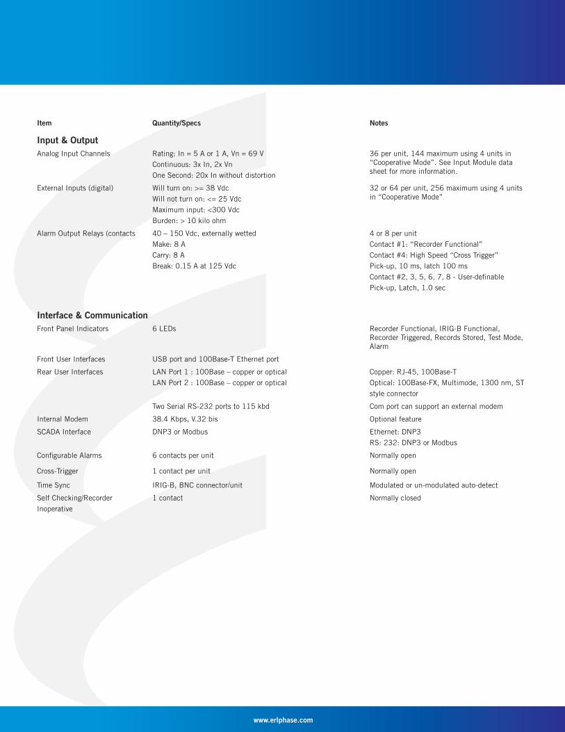
Item Quantity/Specs Notes
Input & Output Analog Input Channels Rating: In = 5 A or 1 A, Vn = 69 V
Continuous: 3x In, 2x VnOne Second: 20x In without distortion
36 per unit, 144 maximum using 4 units in “Cooperative Mode”. See Input Module data sheet for more information.
External Inputs (digital) Will turn on: >= 38 VdcWill not turn on: <= 25 VdcMaximum input: <300 VdcBurden: > 10 kilo ohm
32 or 64 per unit, 256 maximum using 4 units in “Cooperative Mode”
Alarm Output Relays (contacts 40 – 150 Vdc, externally wettedMake: 8 ACarry: 8 ABreak: 0.15 A at 125 Vdc
4 or 8 per unitContact #1: “Recorder Functional”Contact #4: High Speed “Cross Trigger”Pick-up, 10 ms, latch 100 msContact #2, 3, 5, 6, 7, 8 - User-defi nablePick-up, Latch, 1.0 sec
Interface & Communication Front Panel Indicators 6 LEDs Recorder Functional, IRIG-B Functional,
Recorder Triggered, Records Stored, Test Mode, Alarm
Front User Interfaces USB port and 100Base-T Ethernet port
Rear User Interfaces LAN Port 1 : 100Base – copper or opticalLAN Port 2 : 100Base – copper or optical
Copper: RJ-45, 100Base-TOptical: 100Base-FX, Multimode, 1300 nm, ST style connector
Two Serial RS-232 ports to 115 kbd Com port can support an external modem
Internal Modem 38.4 Kbps, V.32 bis Optional feature
SCADA Interface DNP3 or Modbus Ethernet: DNP3RS: 232: DNP3 or Modbus
Confi gurable Alarms 6 contacts per unit Normally open
Cross-Trigger 1 contact per unit Normally open
Time Sync IRIG-B, BNC connector/unit Modulated or un-modulated auto-detect
Self Checking/RecorderInoperative
1 contact Normally closed

www.erlphase.com
Item Quantity/Specs Notes
Phasor Measurement Unit (PMU)Phasor Measurement Unit(PMU)
36 user-selectable phasors Single-phase quantities or 3-phase positive,negative or zero sequence phasors/summated phasors
1 Frequency channel DFREQ will be reported based on frequencychannel confi gured by user
12 Analog values MWatts, MVars and MVA
64 Digital Status data Contact status data reported (4 x 16 bits)
Environmental Ambient Temperature Range -10°C to 55°C IEC 60068-2-1, IEC 60068-2-2
Humidity Up to 95% without condensation IEC 60068-2-30
Insulation Test (Hi-Pot) Power supply, analog inputs (through external isolation modules), external inputs, output contacts at 1.5 kV, 50/60 Hz, 1 minute
IEC 60255-5
Voltage dips, Interruptions, Variations
200 ms interrupt IEC 61000-4-11, IEC 60255-11
Conducted RF Immunity IEC 61000-4-6 Level 3, IEC 60255-22-6 Level 3
Radiated RF Susceptibility IEC 61000-4-6 Level 3, IEC 60255-22-3 Level 3
Electrical Fast Track/Burst IEC 61000-4-4 Level 3, IEC 60255-22-4Class III
Oscillatory Transient ANSI/IEEE C37.90.1-1989, IEC 61000-4-12Level 3, IEC 60255-22-1 Level 3
Oscillatory Vibration IEC 60068-2-6, IEC 60255-21-1 Class 1
Seismic IEC 60068-3-3, IEC 60255-21-3 Class 1
Shock and Bump IEC 60255-21-2 Class 1

www.erlphase.com
4000
Mechanical Drawings
Rear View

www.erlphase.com
TESLA RecorderTop View
Phoenix SMSTB 2,5/16-STterminal blocks accept12-28 ga. stranded wire
4x shielded twisted pair(eg. Belden 9728)
#10 GroundStud
Phoenix MC 1,5/2-STF-5,08terminal blocks accept
16-28 ga. stranded wire
Shield grounded atTESLA end only
Phoenix SMSTB 2,5/8-STterminal blocks accept12-28 ga. stranded wire
Plugs into Analog Inputs(2nd row from bottom)
Power Supply48-250 V dcor120 V ac
Phoenix SMSTB 2,5/8-STterminal blocks accept12-28 ga. stranded wire
DIN rail mount
Phoenix SMSTB 2,5/8-STterminal blocks accept12-28 ga. stranded wire
DC Transducer(up to 1000V)
AC Voltagewith PT
(up to 700VRMS)
B 2350 HWK Recording Signals using DC Input Module
401016DC 4 Channel
Isolated Input Module
(Bottom View)
Up to 4 Inputs per Module
NCNC
Input RIN RFB
NCNC
Input RIN RFB
NCNC
Input RIN RFB
NC
Input RIN RFB
NCNC
Input RIN RFB
RIN RFB
RSH
DC VoltageLow Range0.1 V to 200 V dc FS
DC VoltageHigh Range350 V to 880 V dc FS
AC VoltageLow Range0.1 V to 150 V rms FS
AC VoltageHigh Range200 V to 600 V rms FS
DC Current1 mA to 500 mA dc FS
N t
AC currentwith external shunt
NC
RIN RFB
NC
Current
AC Current(with External Shunt)0.1 V to 1 V rms FS
DC Instrumentation(up to 500mAcurrent loop)
NC
R
NC
Current+ -SH
RSHExternal
Power Supply(Terminals on bottom row not shown)
Recording VA, VB, VC, IA, IB, IC & IN using AC Input Modules
(2nd row from bottom)
Phoenix SMSTB 2,5/16-STterminal blocks accept12-28 ga. stranded wire
Plugs into Analog Inputs
Shield grounded atTESLA end only
3x shielded twisted pair
(Bottom View)
AC 4 Channel
Isolated Current Input Module
0.375" terminal strip spacing
BLine I
I C
AI
DIN rail mount
1
Phoenix SMSTB 2,5/8-ST
12-28 ga. stranded wireterminal blocks accept
401014
(Bottom View)
85
67
34
2 3 4 5 6 7 8
21
(Terminals on bottomrow, not shown)
Power Supply
(eg. Belden 9728)4x shielded twisted pair
V1
1
AC 3 Channel
0.375" terminal strip spacing
Isolated Voltage Input Module
VVA
VoltagesBus
VB C
401006
58
76
34
21
V3V2N1 N2
32 54SPN3 SP
6 7 8
(eg. Belden 9730)
Use Panduit PN12-6HDR-L terminalsMAX insulation diameter .225"Strip length 9/32" +1/32 -0
#10 Gnd Stud
#6 Screws
Phoenix SMSTB 2,5/8-STterminal blocks accept12-28 ga. stranded wire
TESLA RecorderTop View
Currents B
C
ERLPhase Power TechnologiesTel: 204-477-0591Email: [email protected] The specifi cations and product information contained in this document are subject to change without notice. In case of inconsistencies between documents, the version at www.erlphase.com will be considered correct. (D02774R03)