Embed Size (px)
Citation preview
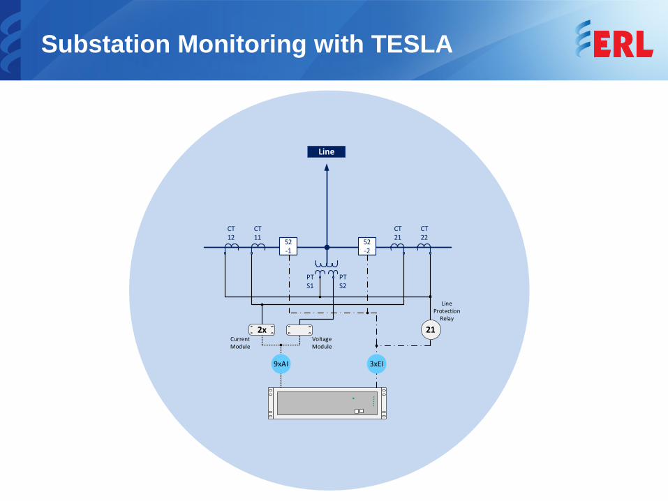
Substation Monitoring with TESLA
PT S1
PT S2
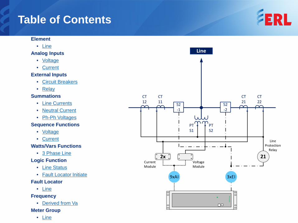
9xAI
Line
CT 12
CT 11
CT 21
CT 2252
-252-1
21
Line Protection
Relay
3xEI
Current Module
Voltage Module
2x
Application Note
TESLA is a power system recorder used to monitor electrical power systems. This application note describes TESLA applied to monitor a substation line bay. Similar procedures can be applied to other substation bays.This application note will show how to:• Configure TESLA’s analog channels, to receive voltage and current
quantities measured from the instrument transformers associated with the line bay
• Configure TESLA’s calculated channels, to derive other electrical quantities, such as summation of currents, neutral current, power quantities, frequency and fault location
Besides monitoring, TESLA can be set to record data simultaneously in 4 time domains: high speed transient fault (seconds), low speed dynamic swing (minutes), continuous data and trend (10 second to 1 hour intervals), based on configurable triggering conditions set independently in either measured or calculated channels; and it can be set to provide real time metering.All selections (i.e. sample rate, enabled triggers, thresholds, etc) are for the purpose of this example only.
PT S1
PT S2
9xAI
Line
CT 12
CT 11
CT 21
CT 2252
-252-1
21
Line Protection
Relay
3xEI
Current Module
Voltage Module
2x
Table of ContentsElement
• LineAnalog Inputs
• Voltage• Current
External Inputs• Circuit Breakers• Relay
Summations• Line Currents• Neutral Current• Ph-Ph Voltages
Sequence Functions • Voltage• Current
Watts/Vars Functions• 3 Phase Line
Logic Function• Line Status• Fault Locator Initiate
Fault Locator• Line
Frequency• Derived from Va
Meter Group• Line
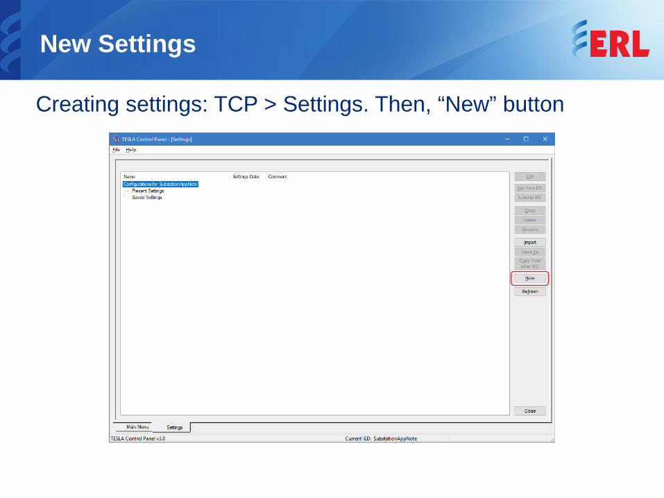
New Settings
Creating settings: TCP > Settings. Then, “New” button
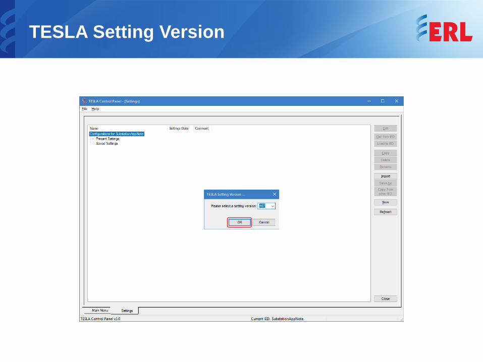
TESLA Setting Version
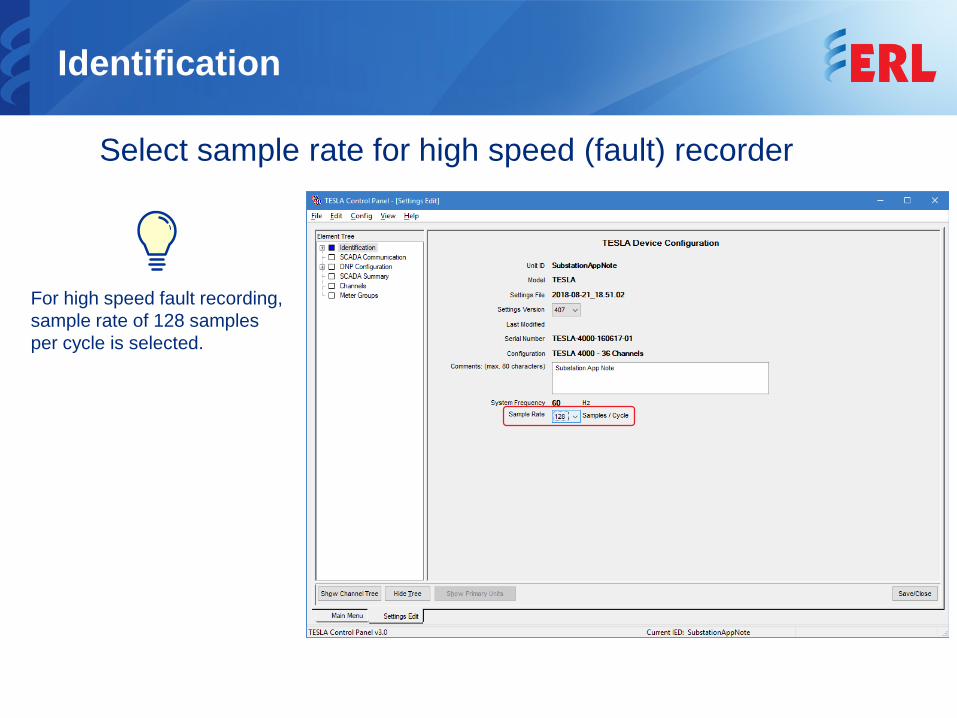
Identification
Select sample rate for high speed (fault) recorder
For high speed fault recording, sample rate of 128 samples per cycle is selected.
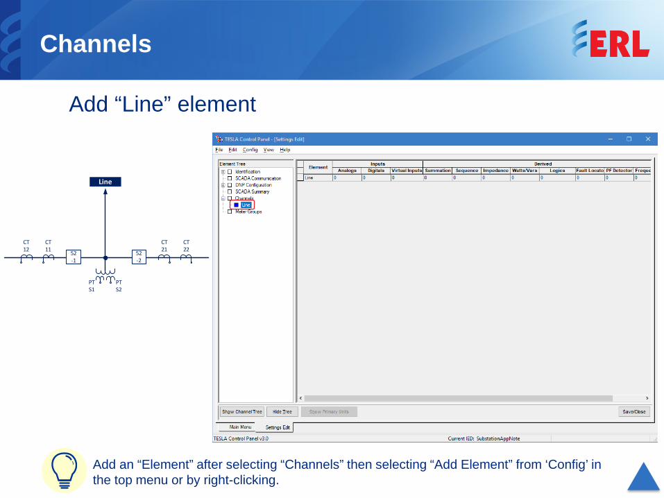
Add an “Element” after selecting “Channels” then selecting “Add Element” from ‘Config’ in the top menu or by right-clicking.
Channels
Add “Line” element
CT 11
CT 12
CT 21
CT 2252
-252-1
PT S1
PT S2
Line
Line
CT 11
CT 12
CT 21
CT 2252
-252-1
PT S1
PT S2
3xAI
Voltage Module
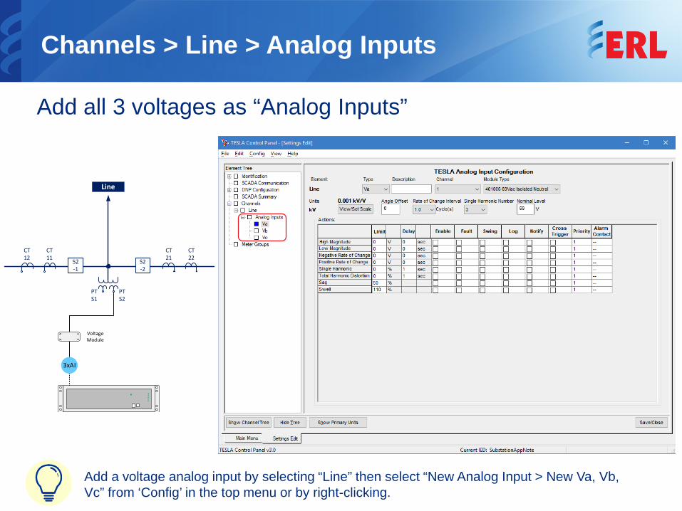
Channels > Line > Analog Inputs
Add all 3 voltages as “Analog Inputs”
Add a voltage analog input by selecting “Line” then select “New Analog Input > New Va, Vb, Vc” from ‘Config’ in the top menu or by right-clicking.
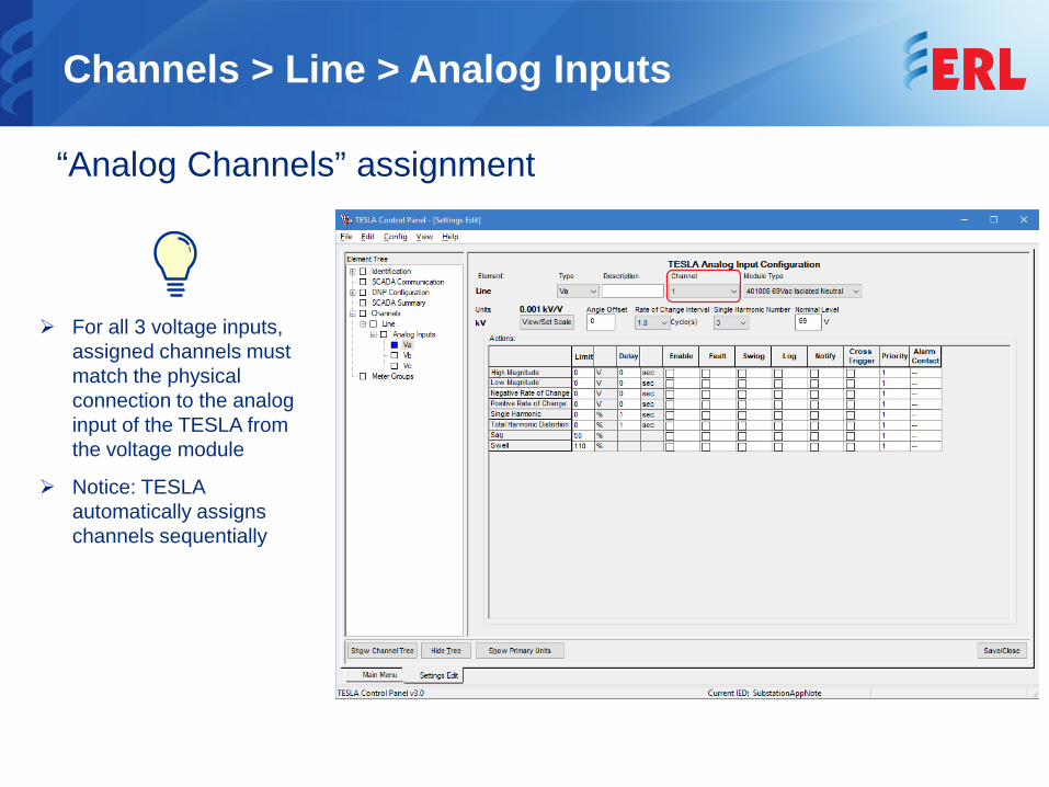
Channels > Line > Analog Inputs
“Analog Channels” assignment
For all 3 voltage inputs, assigned channels must match the physical connection to the analog input of the TESLA from the voltage module
Notice: TESLA automatically assigns channels sequentially
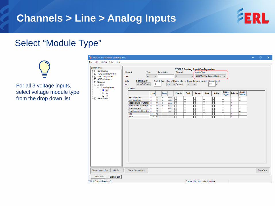
Channels > Line > Analog Inputs
Select “Module Type”
For all 3 voltage inputs, select voltage module type from the drop down list
Channels > Line > Analog Inputs
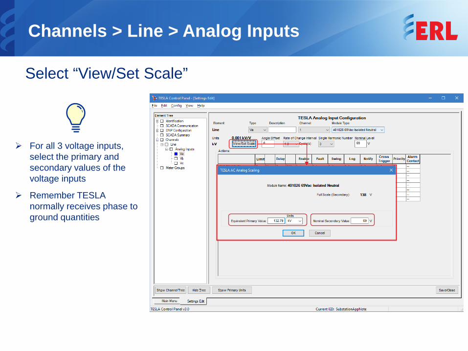
Select “View/Set Scale”
For all 3 voltage inputs, select the primary and secondary values of the voltage inputs
Remember TESLA normally receives phase to ground quantities
Channels > Line > Analog Inputs
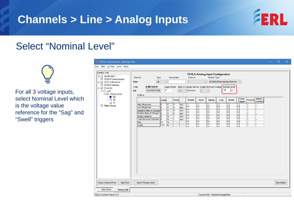
Select “Nominal Level”
For all 3 voltage inputs, select Nominal Level which is the voltage value reference for the “Sag” and “Swell” triggers
Channels > Line > Analog Inputs
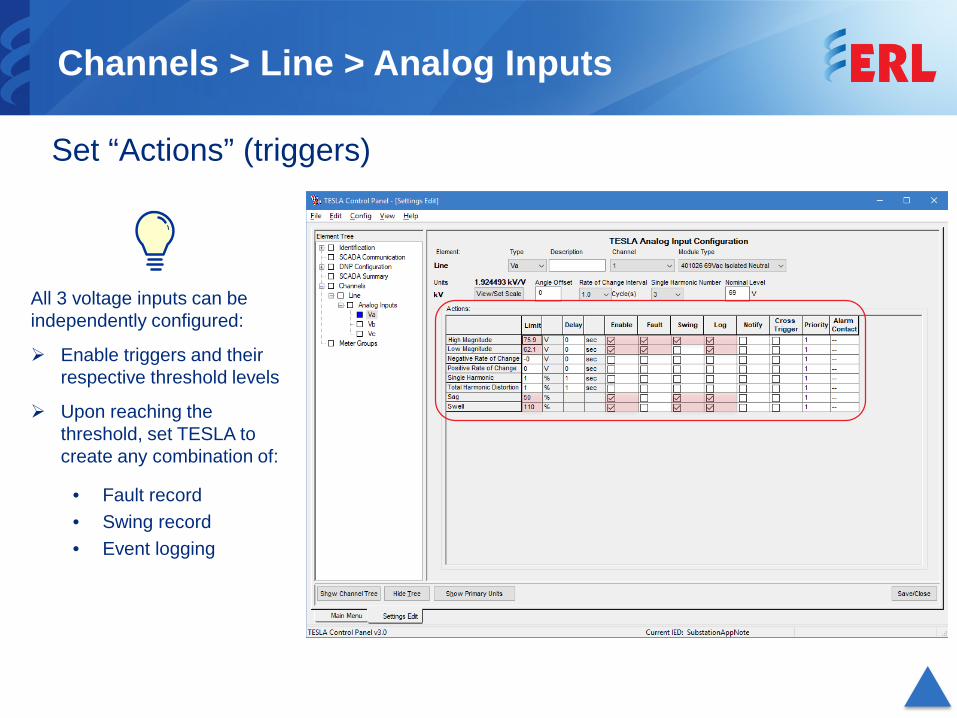
Set “Actions” (triggers)
All 3 voltage inputs can be independently configured:
Enable triggers and their respective threshold levels
Upon reaching the threshold, set TESLA to create any combination of:
• Fault record• Swing record• Event logging
PT S1
PT S2
3xAI
CT 11
CT 12
CT 21
CT 2252
-252-1
Line
Current Module
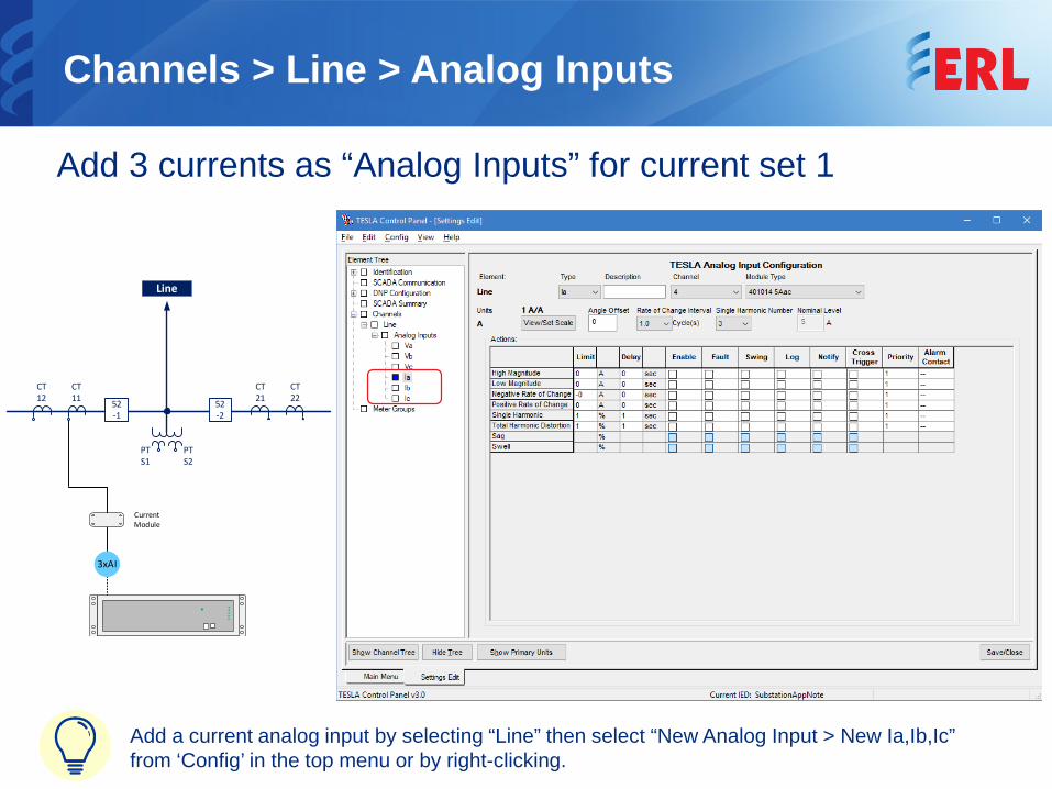
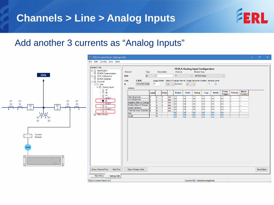
Add a current analog input by selecting “Line” then select “New Analog Input > New Ia,Ib,Ic” from ‘Config’ in the top menu or by right-clicking.
Channels > Line > Analog Inputs
Add 3 currents as “Analog Inputs” for current set 1
Channels > Line > Analog Inputs
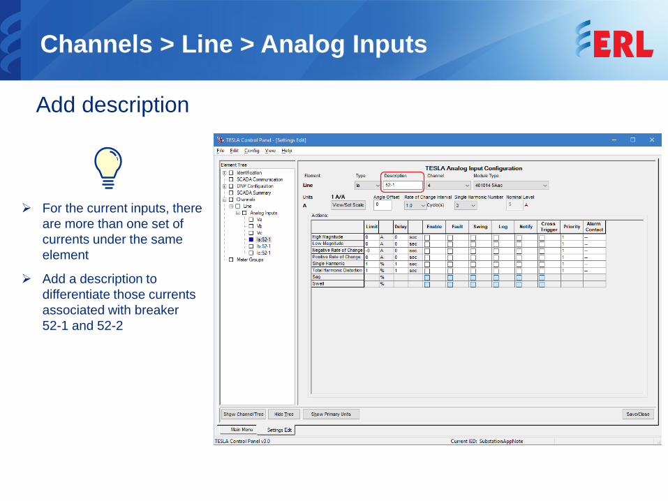
Add description
For the current inputs, there are more than one set of currents under the same element
Add a description to differentiate those currents associated with breaker 52-1 and 52-2
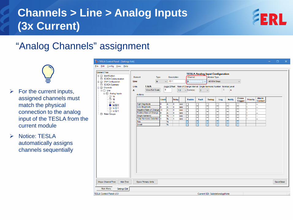
Channels > Line > Analog Inputs(3x Current)“Analog Channels” assignment
For the current inputs, assigned channels must match the physical connection to the analog input of the TESLA from the current module
Notice: TESLA automatically assigns channels sequentially
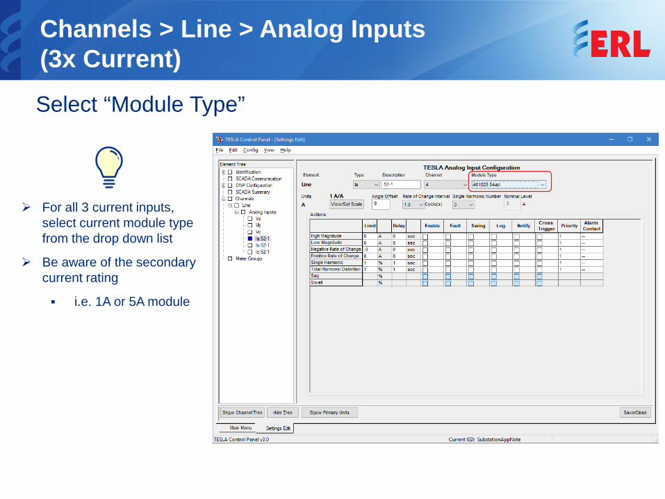
Channels > Line > Analog Inputs(3x Current)Select “Module Type”
For all 3 current inputs, select current module type from the drop down list
Be aware of the secondary current rating
i.e. 1A or 5A module
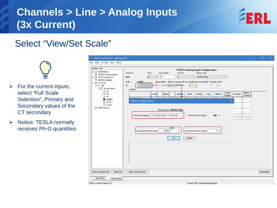
Channels > Line > Analog Inputs(3x Current)Select “View/Set Scale”
For the current inputs, select “Full Scale Selection”, Primary and Secondary values of the CT secondary
Notice: TESLA normally receives Ph-G quantities
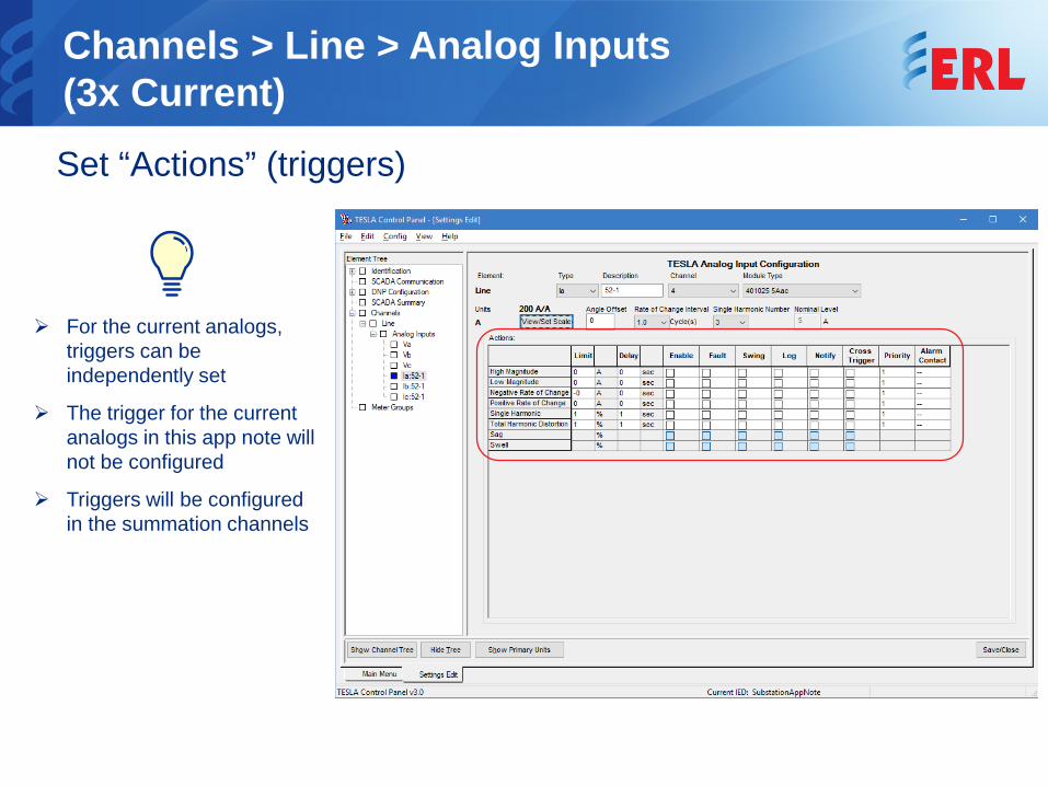
Channels > Line > Analog Inputs(3x Current)Set “Actions” (triggers)
For the current analogs, triggers can be independently set
The trigger for the current analogs in this app note will not be configured
Triggers will be configured in the summation channels
PT S1
PT S2
3xAI
CT 11
CT 12
CT 21
CT 2252
-252-1
Line
Current Module
Channels > Line > Analog Inputs
Add another 3 currents as “Analog Inputs”
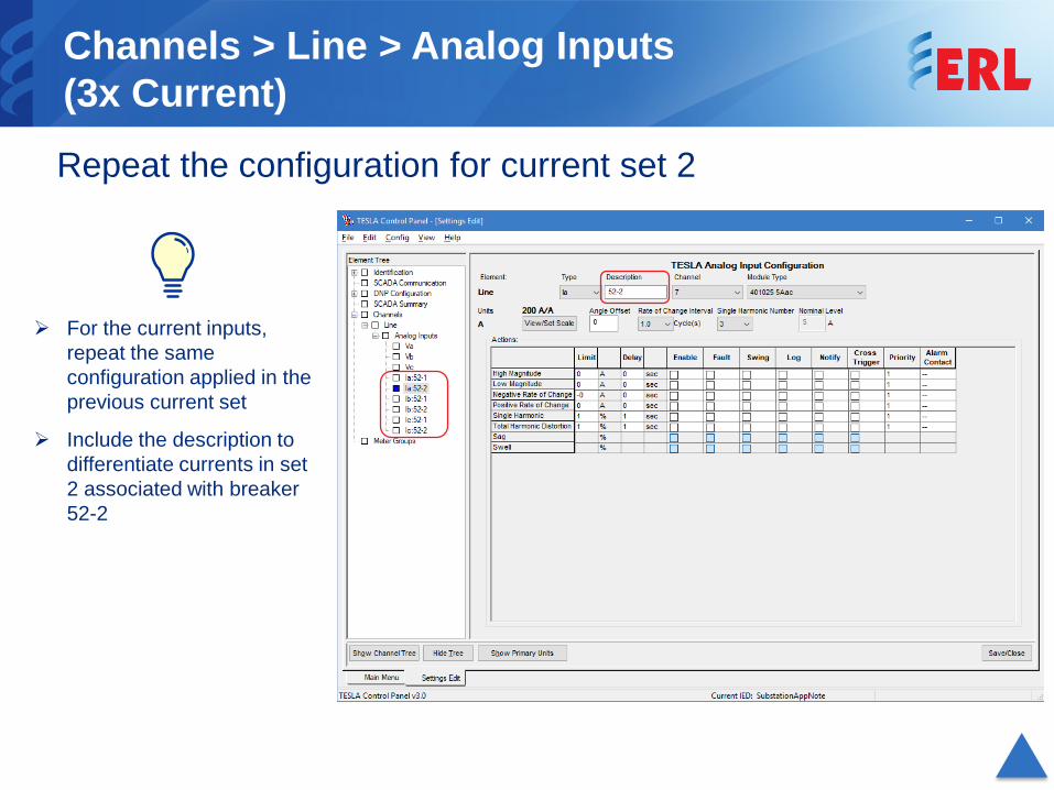
Channels > Line > Analog Inputs(3x Current)Repeat the configuration for current set 2
For the current inputs, repeat the same configuration applied in the previous current set
Include the description to differentiate currents in set 2 associated with breaker 52-2
PT S1
PT S2
1xEI
CT 11
CT 12
CT 21
CT 2252
-252-1
Line
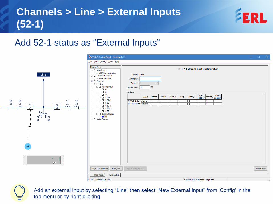
Channels > Line > External Inputs(52-1)Add 52-1 status as “External Inputs”
Add an external input by selecting “Line” then select “New External Input” from ‘Config’ in the top menu or by right-clicking.
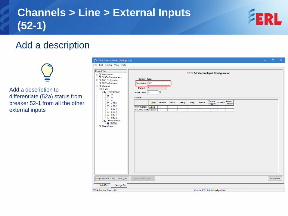
Channels > Line > External Inputs(52-1)Add a description
Add a description to differentiate (52a) status from breaker 52-1 from all the other external inputs
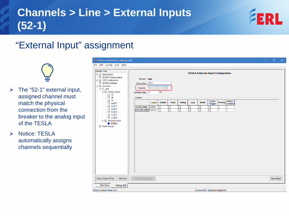
Channels > Line > External Inputs(52-1)“External Input” assignment
The “52-1” external input, assigned channel must match the physical connection from the breaker to the analog input of the TESLA
Notice: TESLA automatically assigns channels sequentially
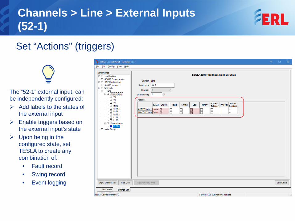
Channels > Line > External Inputs(52-1)Set “Actions” (triggers)
The “52-1” external input, can be independently configured: Add labels to the states of
the external input Enable triggers based on
the external input’s state Upon being in the
configured state, set TESLA to create any combination of:
• Fault record• Swing record• Event logging
PT S1
PT S2
1xEI
CT 11
CT 12
CT 21
CT 2252
-252-1
Line
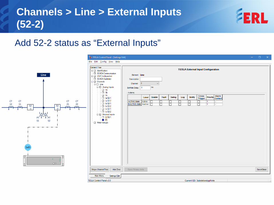
Channels > Line > External Inputs(52-2)Add 52-2 status as “External Inputs”
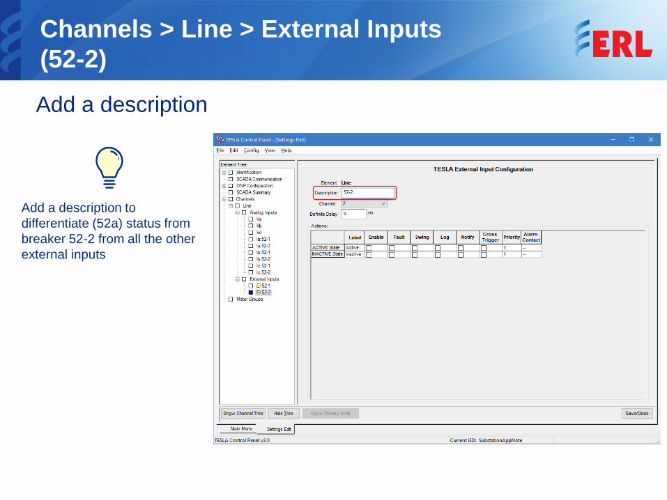
Channels > Line > External Inputs(52-2)Add a description
Add a description to differentiate (52a) status from breaker 52-2 from all the other external inputs
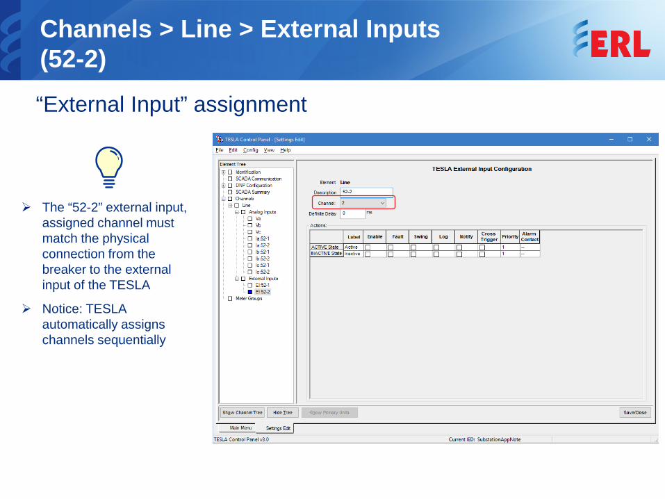
Channels > Line > External Inputs(52-2)“External Input” assignment
The “52-2” external input, assigned channel must match the physical connection from the breaker to the external input of the TESLA
Notice: TESLA automatically assigns channels sequentially
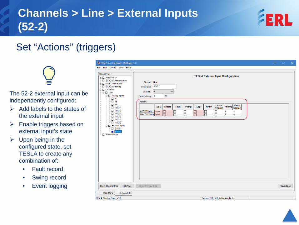
Channels > Line > External Inputs(52-2)Set “Actions” (triggers)
The 52-2 external input can be independently configured: Add labels to the states of
the external input Enable triggers based on
external input’s state Upon being in the
configured state, set TESLA to create any combination of:
• Fault record• Swing record• Event logging
PT S1
PT S2
1xEI
Line
CT 11
CT 12
CT 21
CT 2252
-252-1
21Line Protection
Relay
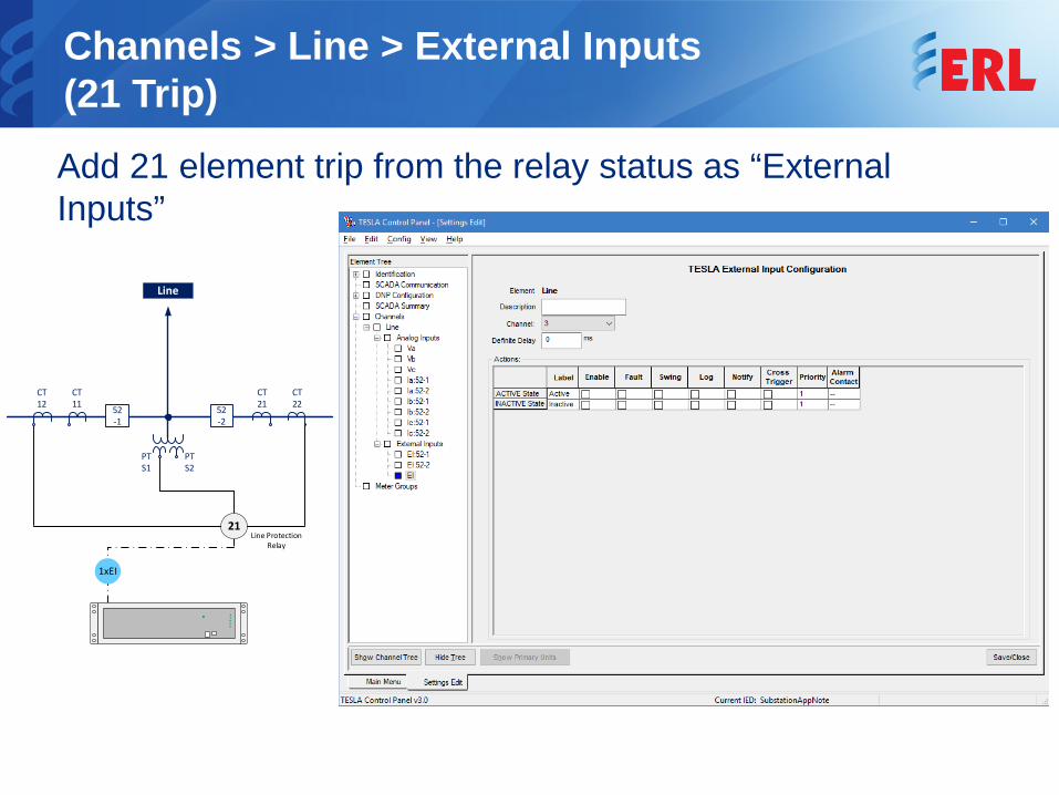
Channels > Line > External Inputs(21 Trip)Add 21 element trip from the relay status as “External Inputs”
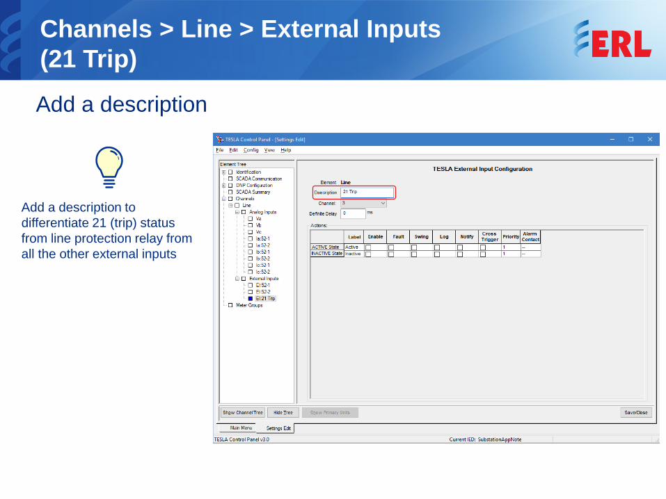
Channels > Line > External Inputs(21 Trip)Add a description
Add a description to differentiate 21 (trip) status from line protection relay from all the other external inputs
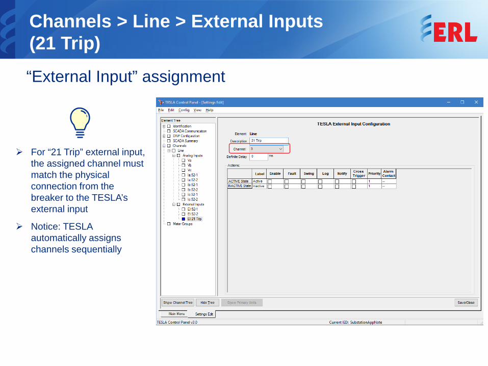
Channels > Line > External Inputs(21 Trip)“External Input” assignment
For “21 Trip” external input, the assigned channel must match the physical connection from the breaker to the TESLA’s external input
Notice: TESLA automatically assigns channels sequentially
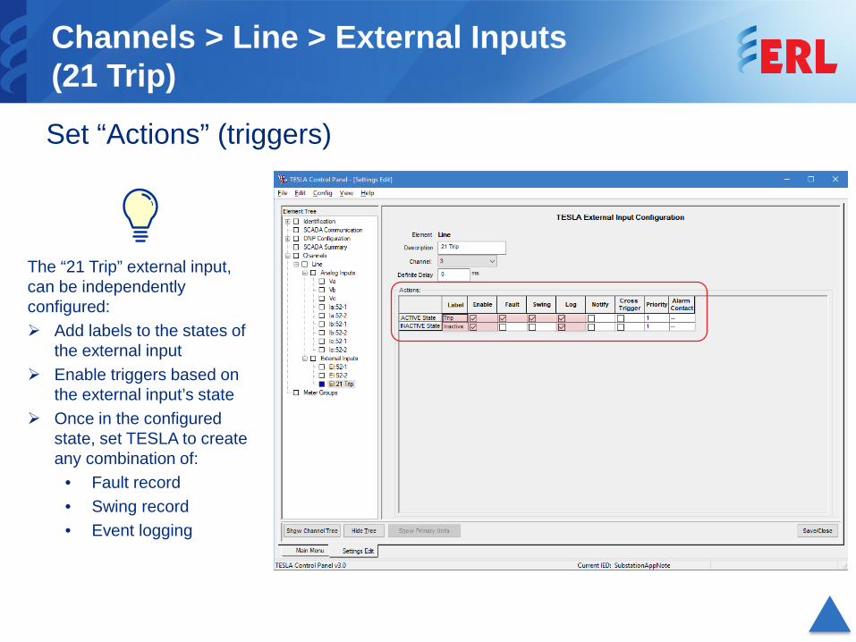
Channels > Line > External Inputs(21 Trip)Set “Actions” (triggers)
The “21 Trip” external input, can be independently configured: Add labels to the states of
the external input Enable triggers based on
the external input’s state Once in the configured
state, set TESLA to create any combination of:
• Fault record• Swing record• Event logging
PT S1
PT S2
9xAI
Line
CT 12
CT 11
CT 21
CT 2252
-252-1
21
Line Protection
Relay
3xEI
Current Module
Voltage Module
2x
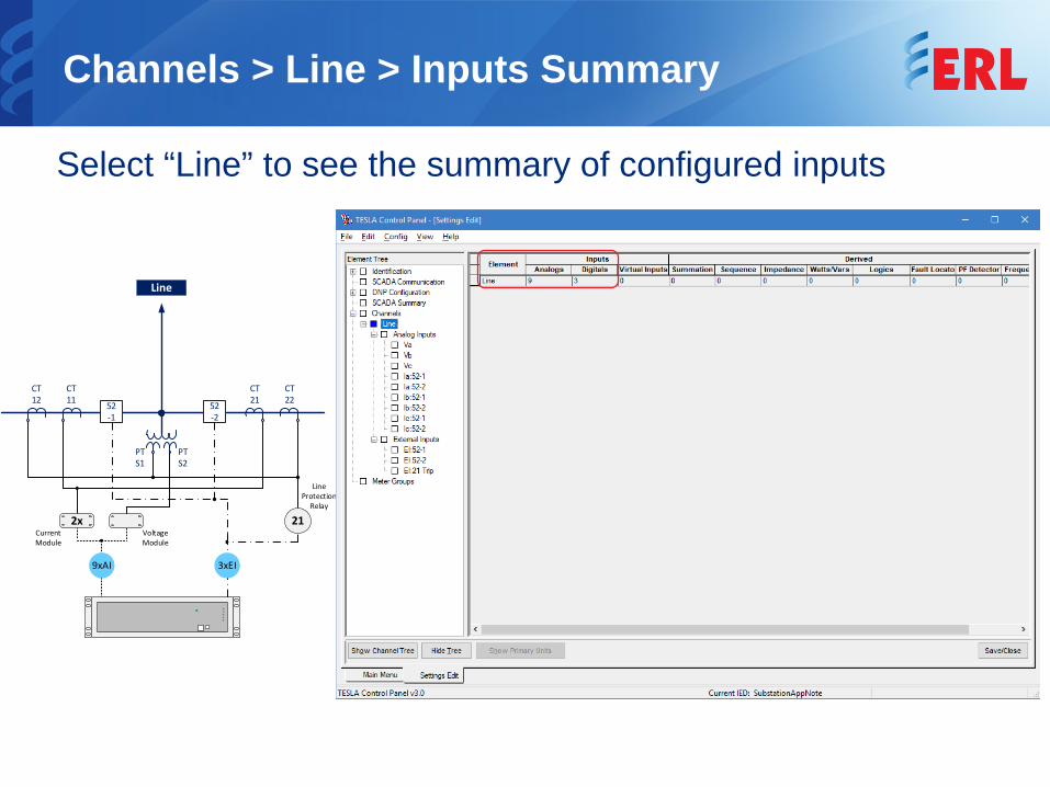
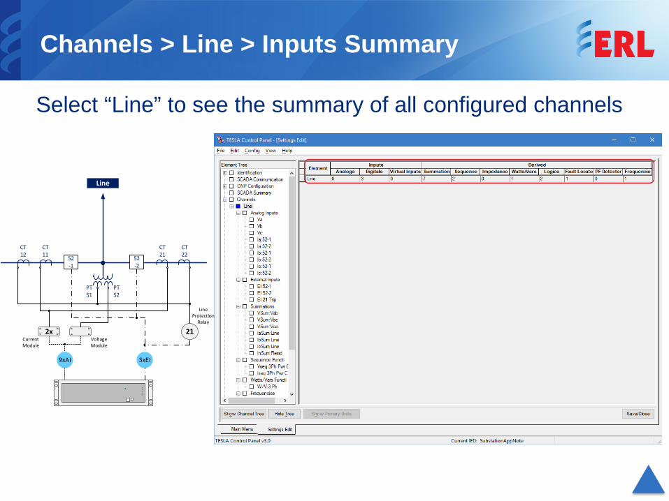
Channels > Line > Inputs Summary
Select “Line” to see the summary of configured inputs
PT S1
PT S2
6xAI
Line
CT 12
CT 21
CT 2252
-252-1
Current Module
i 52-1 i52-1
i Line
2x
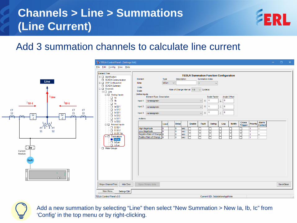
Channels > Line > Summations (Line Current) Add 3 summation channels to calculate line current
Add a new summation by selecting “Line” then select “New Summation > New Ia, Ib, Ic” from ‘Config’ in the top menu or by right-clicking.
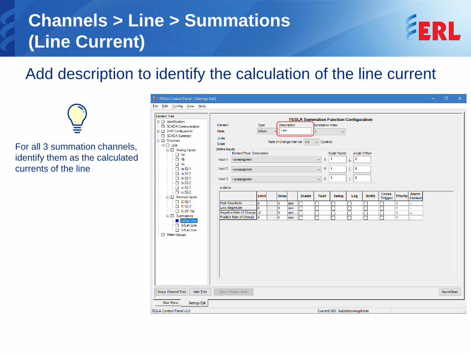
Channels > Line > Summations (Line Current) Add description to identify the calculation of the line current
For all 3 summation channels, identify them as the calculated currents of the line
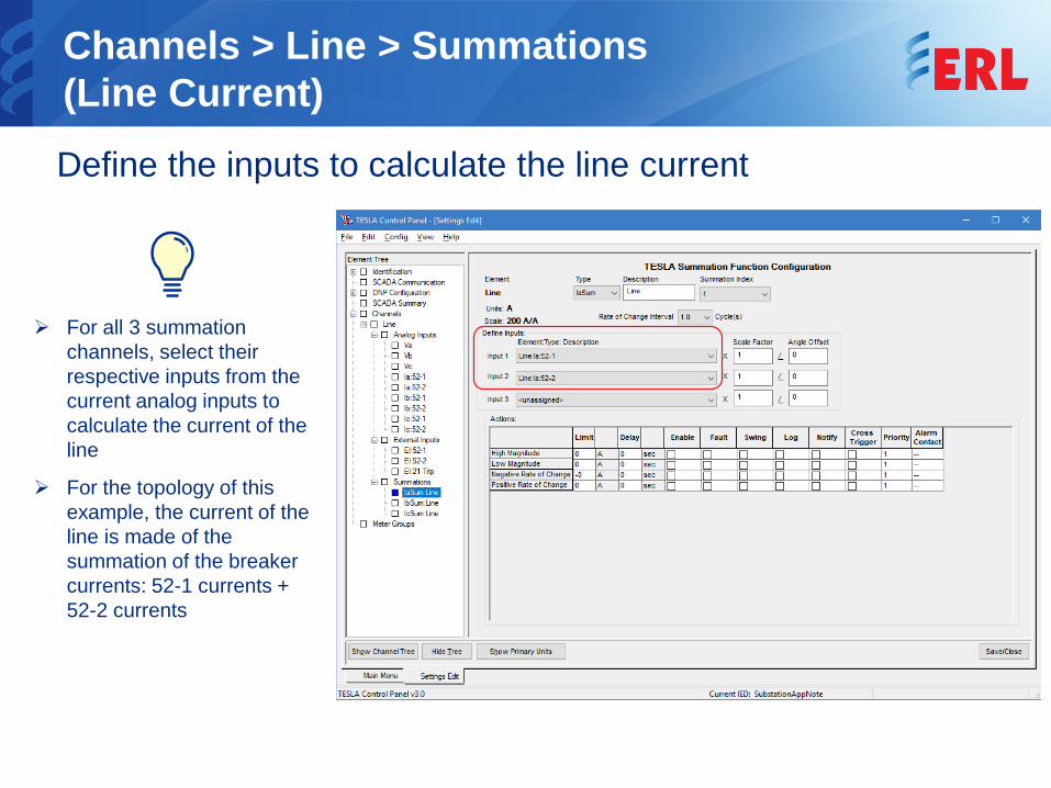
Channels > Line > Summations (Line Current) Define the inputs to calculate the line current
For all 3 summation channels, select their respective inputs from the current analog inputs to calculate the current of the line
For the topology of this example, the current of the line is made of the summation of the breaker currents: 52-1 currents + 52-2 currents
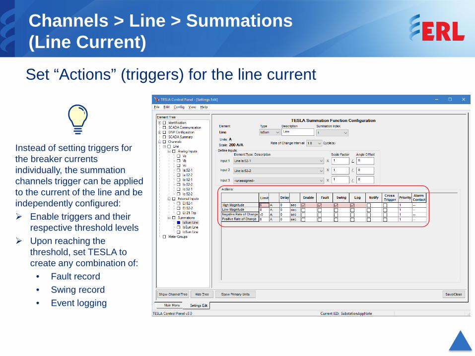
Channels > Line > Summations (Line Current) Set “Actions” (triggers) for the line current
Instead of setting triggers for the breaker currents individually, the summation channels trigger can be applied to the current of the line and be independently configured: Enable triggers and their
respective threshold levels Upon reaching the
threshold, set TESLA to create any combination of:
• Fault record• Swing record• Event logging
PT S1
PT S2
6xAI
Line
CT 12
CT 21
CT 2252
-252-1
Current Module
i Line = Isum
2x
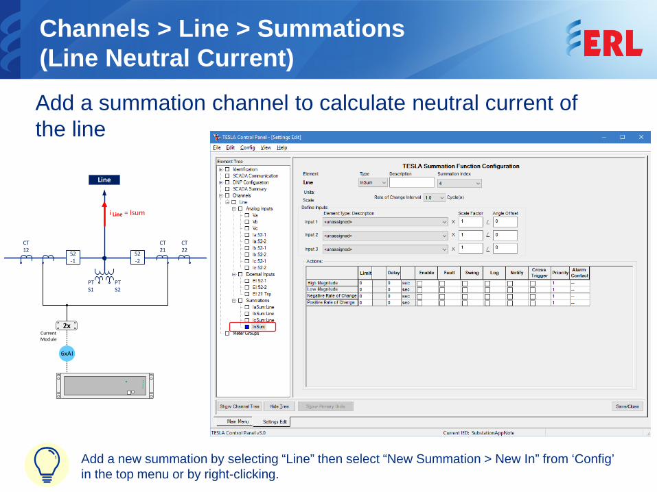
Channels > Line > Summations (Line Neutral Current) Add a summation channel to calculate neutral current of the line
Add a new summation by selecting “Line” then select “New Summation > New In” from ‘Config’ in the top menu or by right-clicking.
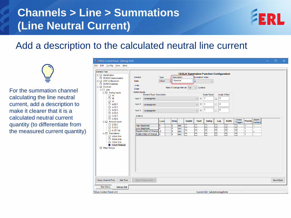
Channels > Line > Summations (Line Neutral Current) Add a description to the calculated neutral line current
For the summation channel calculating the line neutral current, add a description to make it clearer that it is a calculated neutral current quantity (to differentiate from the measured current quantity)
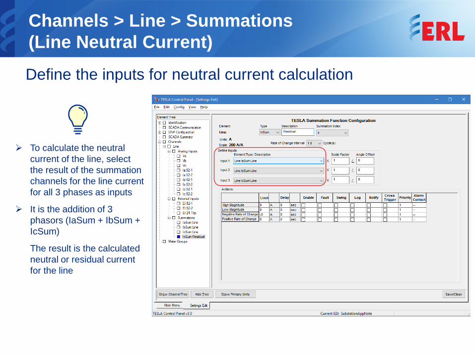
Channels > Line > Summations (Line Neutral Current) Define the inputs for neutral current calculation
To calculate the neutral current of the line, select the result of the summation channels for the line current for all 3 phases as inputs
It is the addition of 3 phasors (IaSum + IbSum + IcSum)
The result is the calculated neutral or residual current for the line
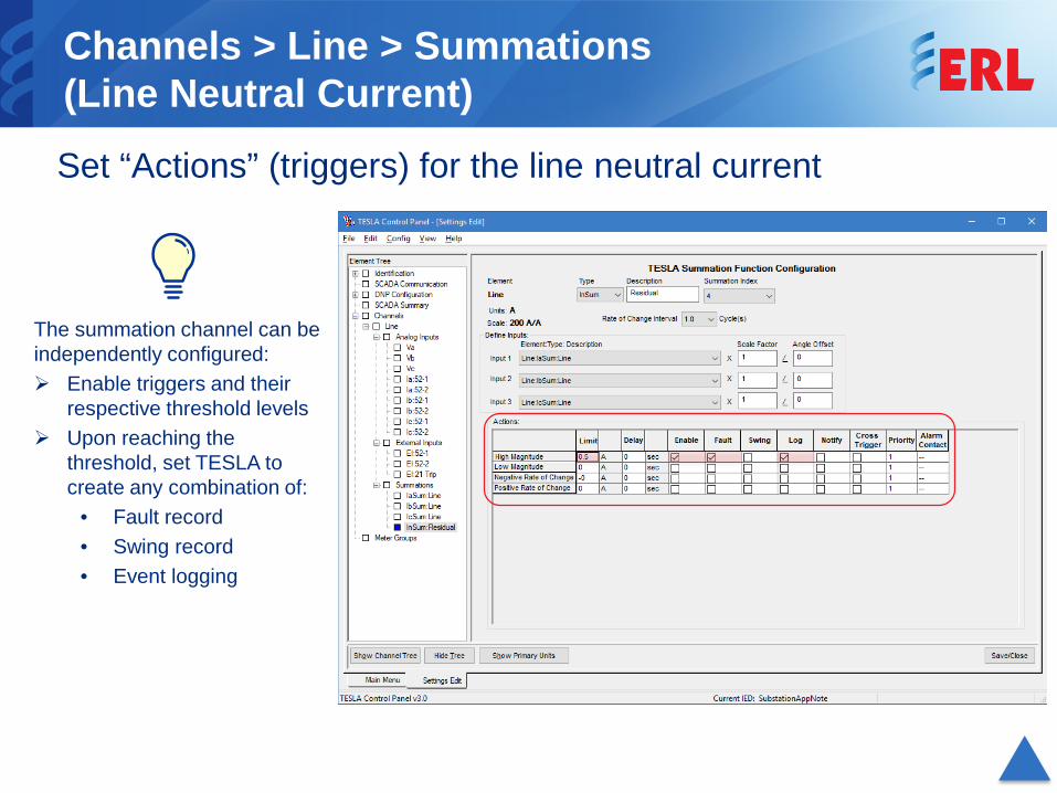
Channels > Line > Summations (Line Neutral Current) Set “Actions” (triggers) for the line neutral current
The summation channel can be independently configured: Enable triggers and their
respective threshold levels Upon reaching the
threshold, set TESLA to create any combination of:
• Fault record• Swing record• Event logging
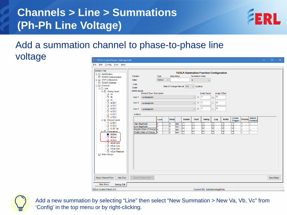
Channels > Line > Summations (Ph-Ph Line Voltage) Add a summation channel to phase-to-phase line voltage
Add a new summation by selecting “Line” then select “New Summation > New Va, Vb, Vc” from ‘Config’ in the top menu or by right-clicking.
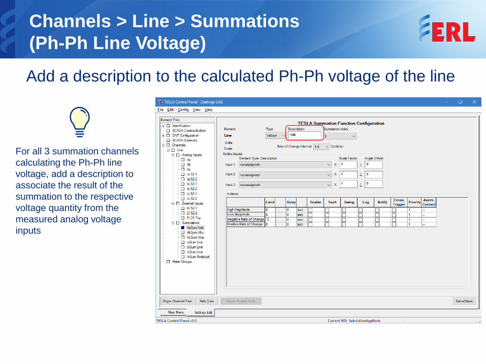
Channels > Line > Summations (Ph-Ph Line Voltage) Add a description to the calculated Ph-Ph voltage of the line
For all 3 summation channels calculating the Ph-Ph line voltage, add a description to associate the result of the summation to the respective voltage quantity from the measured analog voltage inputs
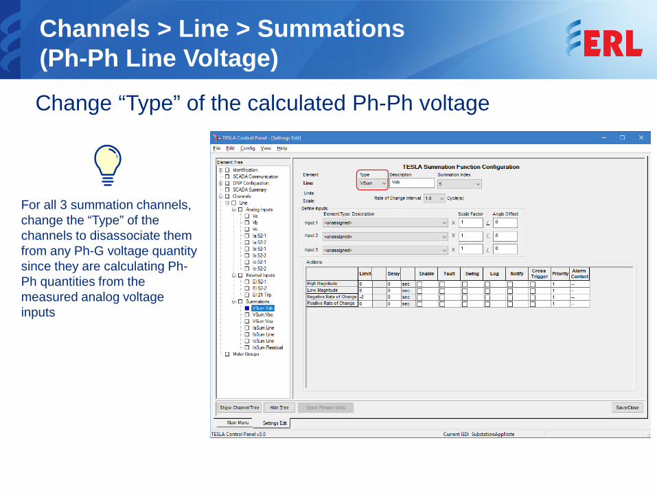
Channels > Line > Summations (Ph-Ph Line Voltage) Change “Type” of the calculated Ph-Ph voltage
For all 3 summation channels, change the “Type” of the channels to disassociate them from any Ph-G voltage quantity since they are calculating Ph-Ph quantities from the measured analog voltage inputs
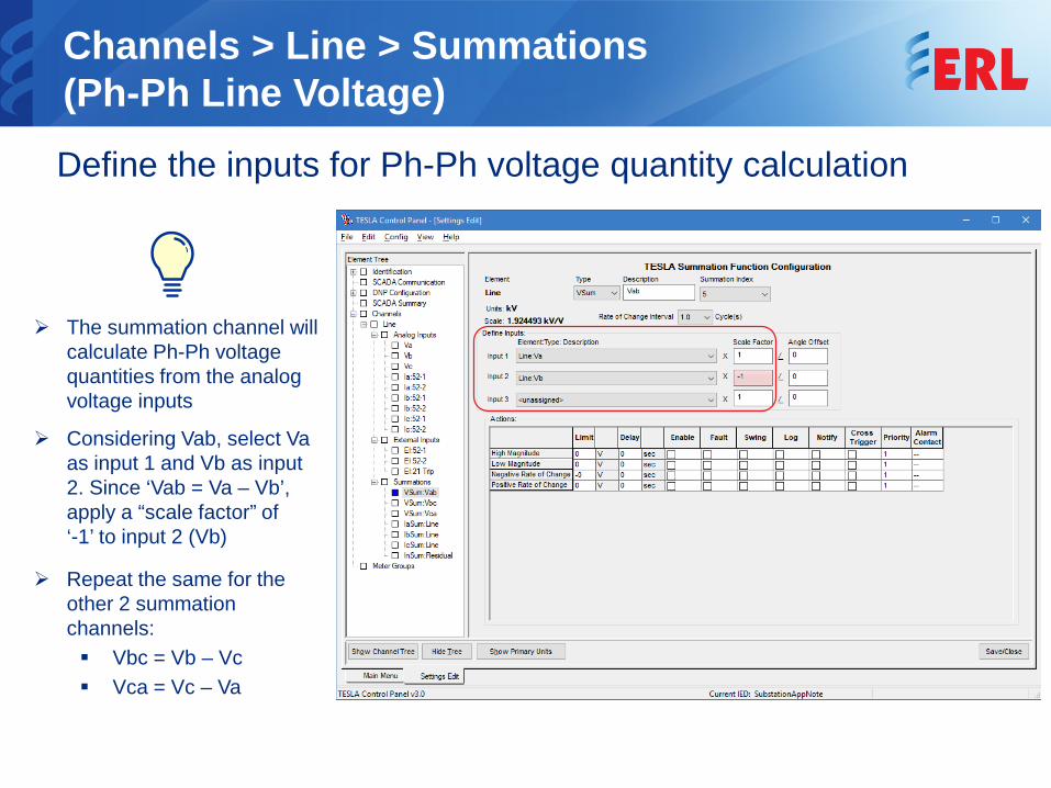
Channels > Line > Summations (Ph-Ph Line Voltage) Define the inputs for Ph-Ph voltage quantity calculation
The summation channel will calculate Ph-Ph voltage quantities from the analog voltage inputs
Considering Vab, select Va as input 1 and Vb as input 2. Since ‘Vab = Va – Vb’, apply a “scale factor” of ‘-1’ to input 2 (Vb)
Repeat the same for the other 2 summation channels: Vbc = Vb – Vc Vca = Vc – Va
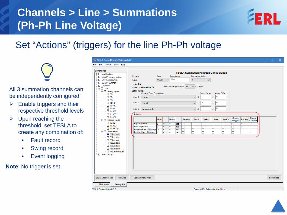
Channels > Line > Summations (Ph-Ph Line Voltage) Set “Actions” (triggers) for the line Ph-Ph voltage
All 3 summation channels can be independently configured: Enable triggers and their
respective threshold levels Upon reaching the
threshold, set TESLA to create any combination of:
• Fault record• Swing record• Event logging
Note: No trigger is set
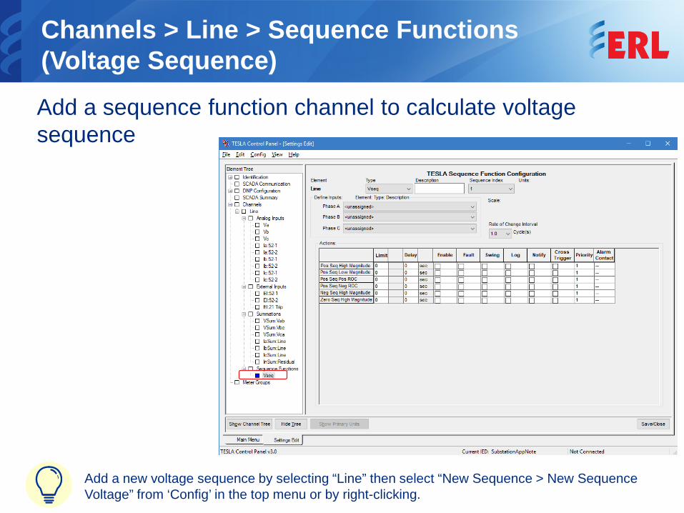
Channels > Line > Sequence Functions (Voltage Sequence) Add a sequence function channel to calculate voltage sequence
Add a new voltage sequence by selecting “Line” then select “New Sequence > New Sequence Voltage” from ‘Config’ in the top menu or by right-clicking.
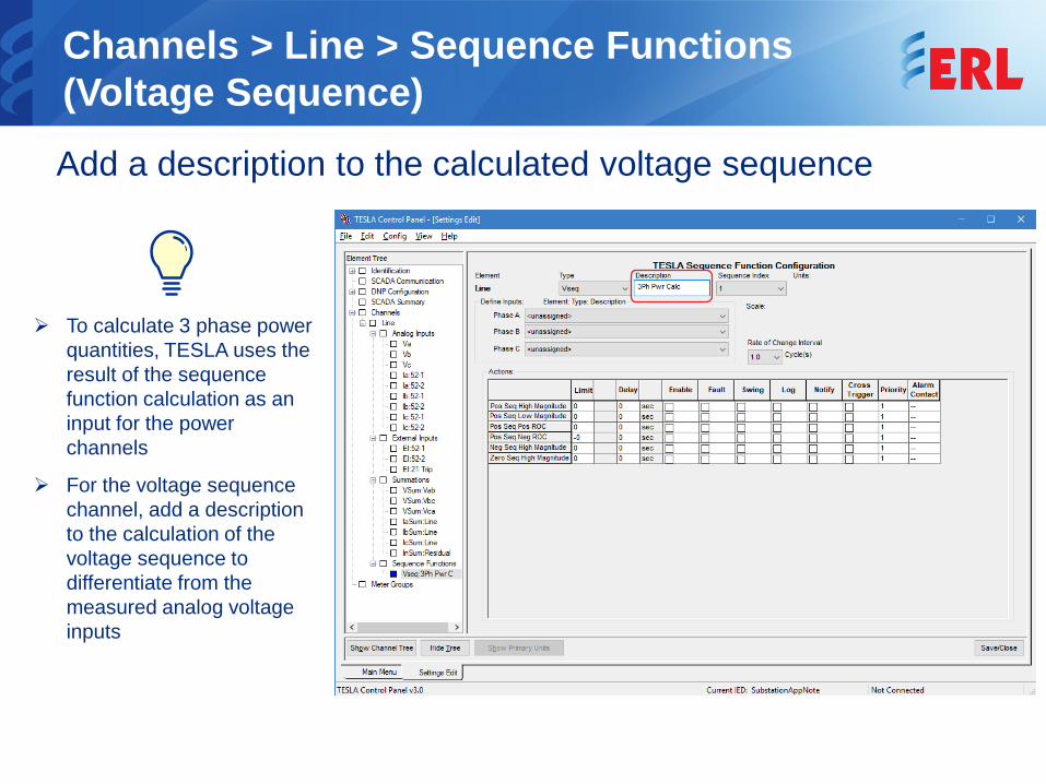
Channels > Line > Sequence Functions (Voltage Sequence) Add a description to the calculated voltage sequence
To calculate 3 phase power quantities, TESLA uses the result of the sequence function calculation as an input for the power channels
For the voltage sequence channel, add a description to the calculation of the voltage sequence to differentiate from the measured analog voltage inputs
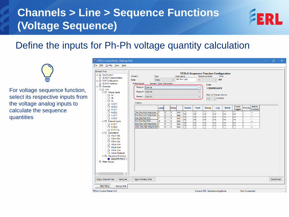
Channels > Line > Sequence Functions (Voltage Sequence) Define the inputs for Ph-Ph voltage quantity calculation
For voltage sequence function, select its respective inputs from the voltage analog inputs to calculate the sequence quantities
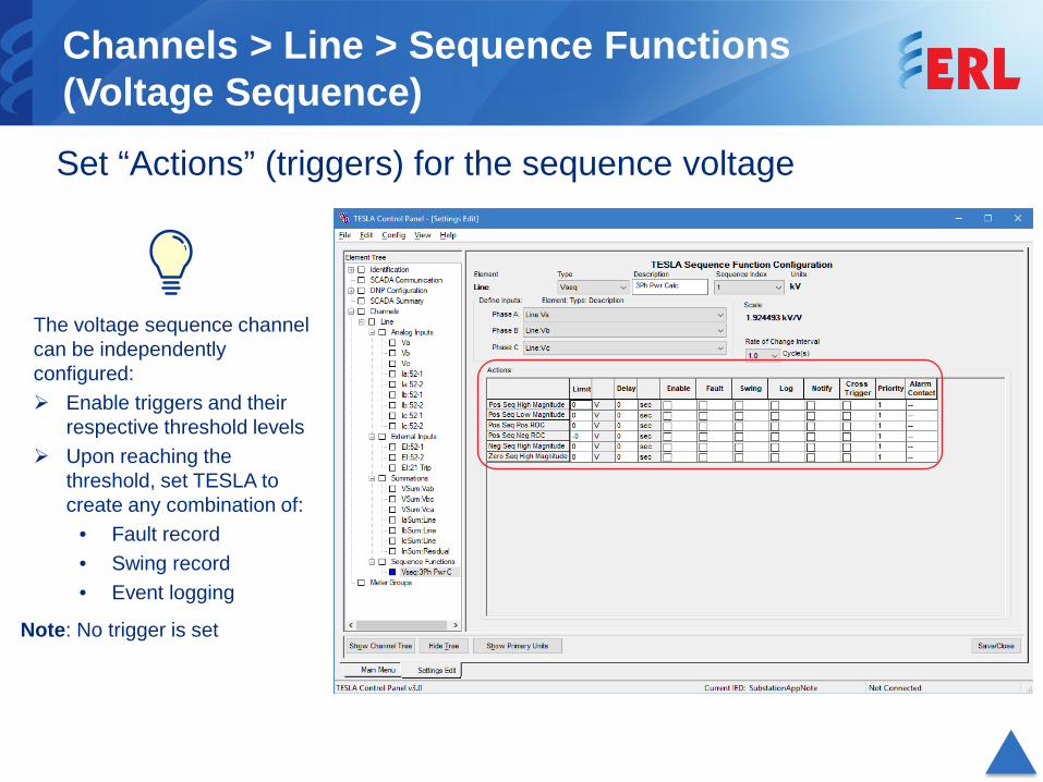
Channels > Line > Sequence Functions (Voltage Sequence) Set “Actions” (triggers) for the sequence voltage
The voltage sequence channel can be independently configured: Enable triggers and their
respective threshold levels Upon reaching the
threshold, set TESLA to create any combination of:
• Fault record• Swing record• Event logging
Note: No trigger is set
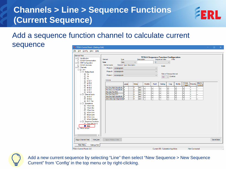
Channels > Line > Sequence Functions (Current Sequence) Add a sequence function channel to calculate current sequence
Add a new current sequence by selecting “Line” then select “New Sequence > New Sequence Current” from ‘Config’ in the top menu or by right-clicking.
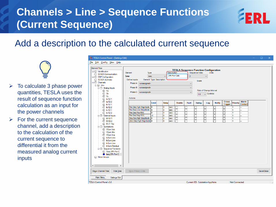
Channels > Line > Sequence Functions (Current Sequence) Add a description to the calculated current sequence
To calculate 3 phase power quantities, TESLA uses the result of sequence function calculation as an input for the power channels
For the current sequence channel, add a description to the calculation of the current sequence to differential it from the measured analog current inputs
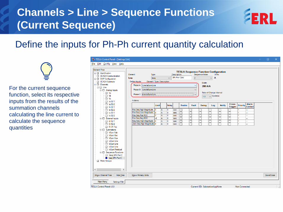
Channels > Line > Sequence Functions (Current Sequence) Define the inputs for Ph-Ph current quantity calculation
For the current sequence function, select its respective inputs from the results of the summation channels calculating the line current to calculate the sequence quantities

Channels > Line > Sequence Functions (Current Sequence) Set “Actions” (triggers) for the sequence current
The current sequence channel, can be independently configured: Enable triggers and their
respective threshold levels Upon reaching the
threshold, set TESLA to create any combination of:
• Fault record• Swing record• Event logging
Note: No trigger is set
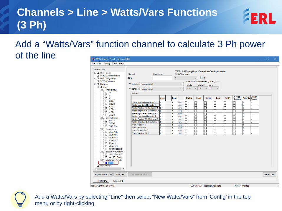
Channels > Line > Watts/Vars Functions (3 Ph) Add a “Watts/Vars” function channel to calculate 3 Ph power of the line
Add a Watts/Vars by selecting “Line” then select “New Watts/Vars” from ‘Config’ in the top menu or by right-clicking.
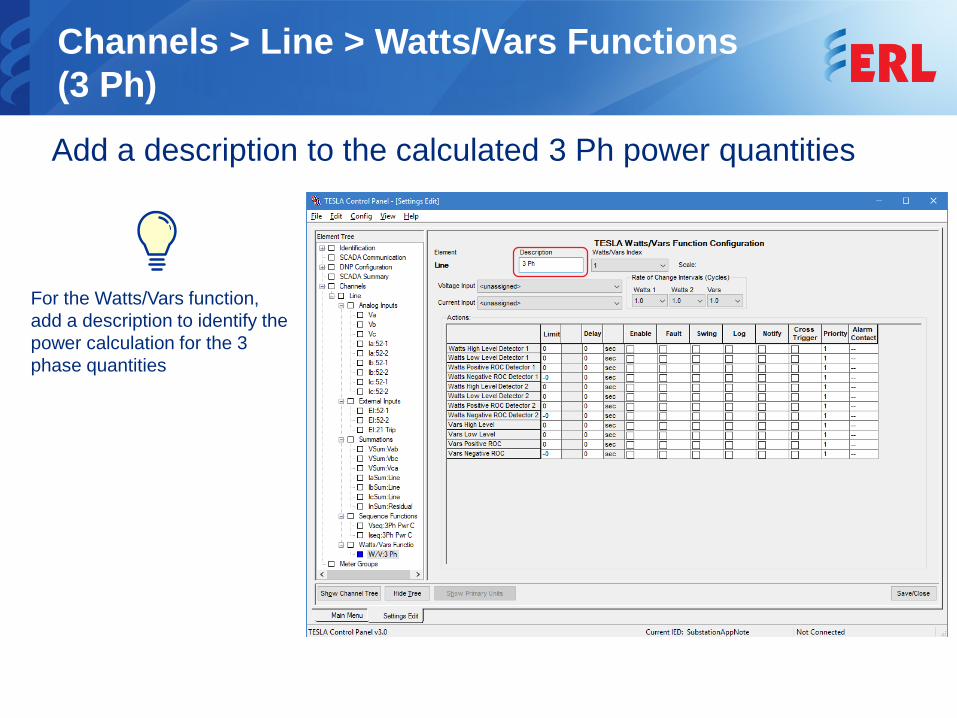
Channels > Line > Watts/Vars Functions (3 Ph) Add a description to the calculated 3 Ph power quantities
For the Watts/Vars function, add a description to identify the power calculation for the 3 phase quantities
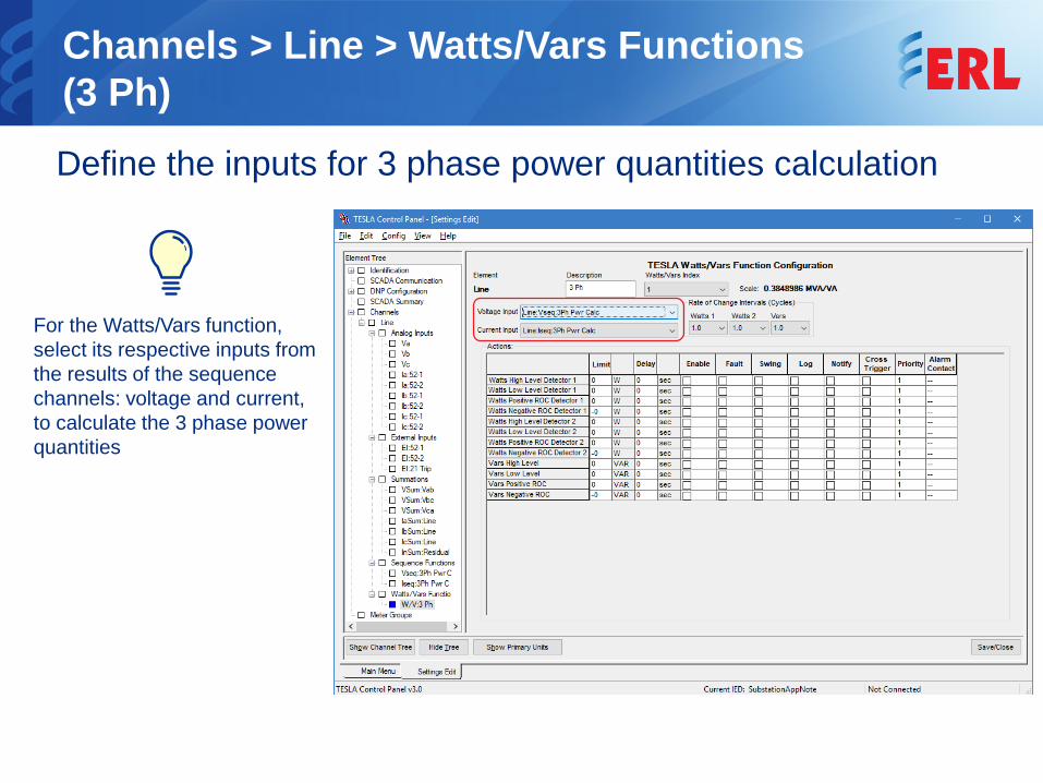
Channels > Line > Watts/Vars Functions (3 Ph) Define the inputs for 3 phase power quantities calculation
For the Watts/Vars function, select its respective inputs from the results of the sequence channels: voltage and current, to calculate the 3 phase power quantities
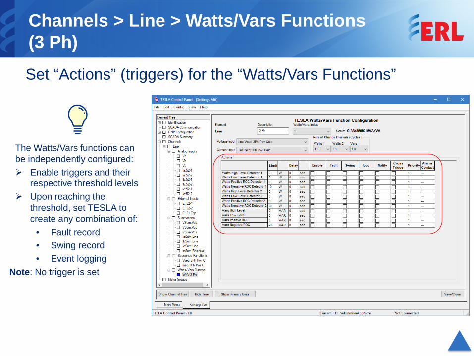
Channels > Line > Watts/Vars Functions (3 Ph) Set “Actions” (triggers) for the “Watts/Vars Functions”
The Watts/Vars functions can be independently configured: Enable triggers and their
respective threshold levels Upon reaching the
threshold, set TESLA to create any combination of:
• Fault record• Swing record• Event logging
Note: No trigger is set
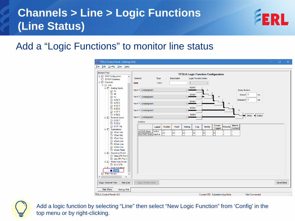
Channels > Line > Logic Functions(Line Status) Add a “Logic Functions” to monitor line status
Add a logic function by selecting “Line” then select “New Logic Function” from ‘Config’ in the top menu or by right-clicking.
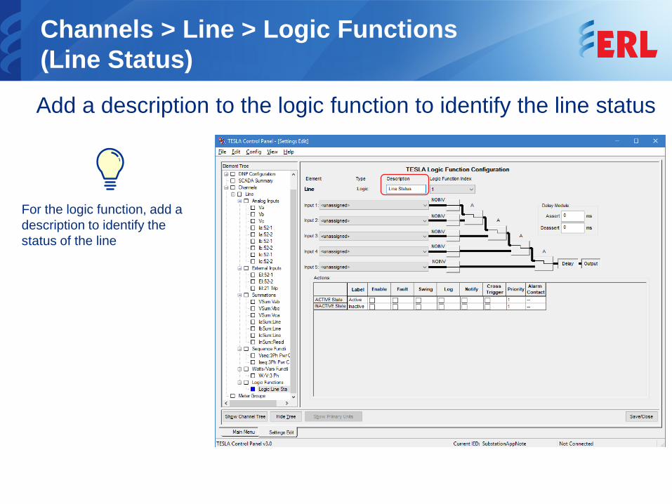
Channels > Line > Logic Functions(Line Status) Add a description to the logic function to identify the line status
For the logic function, add a description to identify the status of the line
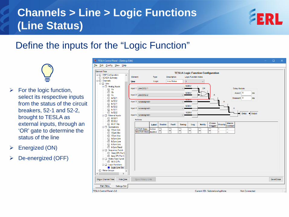
Channels > Line > Logic Functions(Line Status) Define the inputs for the “Logic Function”
For the logic function, select its respective inputs from the status of the circuit breakers, 52-1 and 52-2, brought to TESLA as external inputs, through an ‘OR’ gate to determine the status of the line
Energized (ON)
De-energized (OFF)
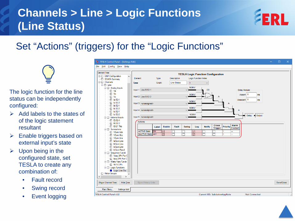
Channels > Line > Logic Functions(Line Status) Set “Actions” (triggers) for the “Logic Functions”
The logic function for the line status can be independently configured: Add labels to the states of
of the logic statement resultant
Enable triggers based on external input’s state
Upon being in the configured state, set TESLA to create any combination of:
• Fault record• Swing record• Event logging
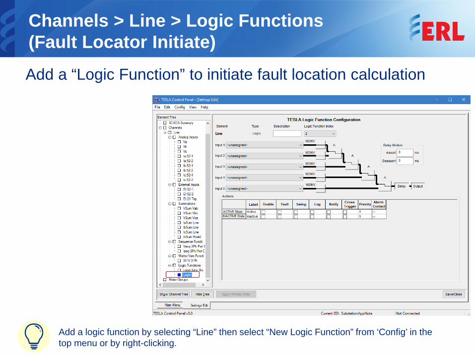
Channels > Line > Logic Functions(Fault Locator Initiate) Add a “Logic Function” to initiate fault location calculation
Add a logic function by selecting “Line” then select “New Logic Function” from ‘Config’ in the top menu or by right-clicking.
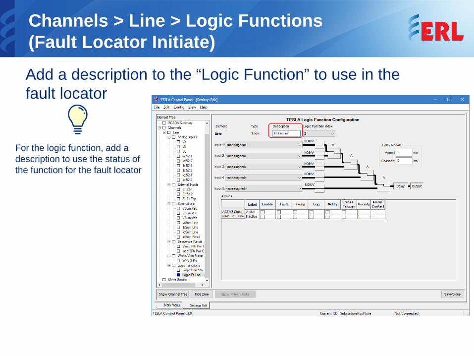
Channels > Line > Logic Functions(Fault Locator Initiate) Add a description to the “Logic Function” to use in the fault locator
For the logic function, add a description to use the status of the function for the fault locator
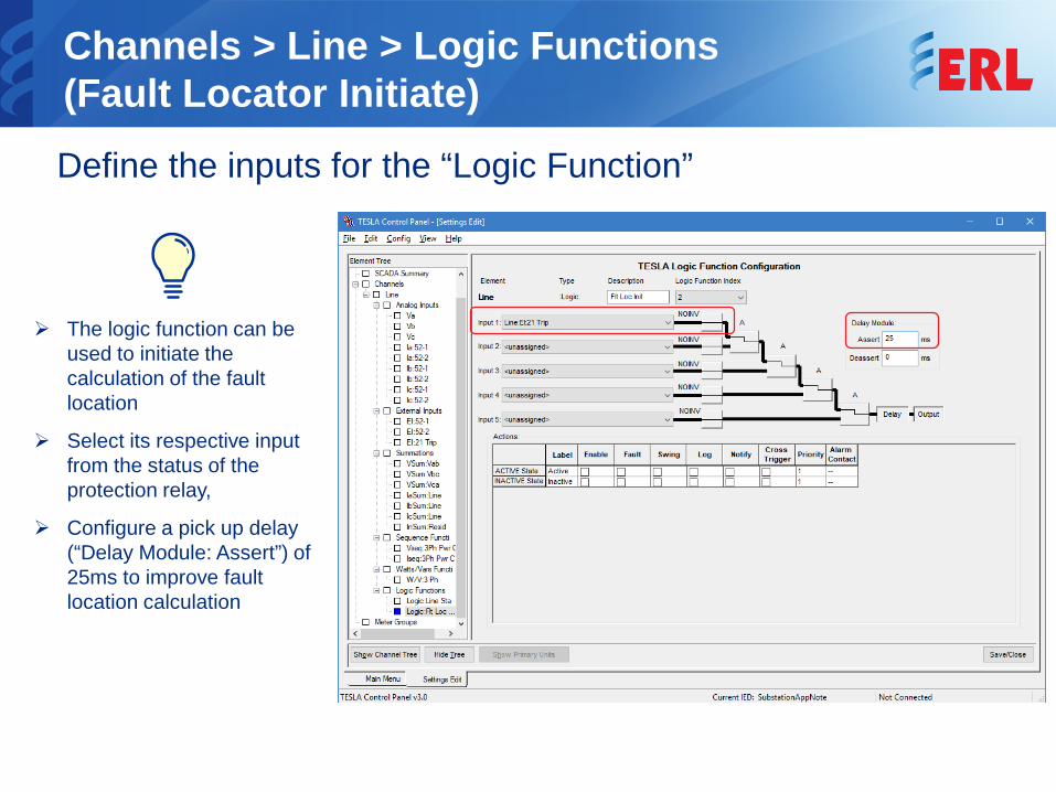
Channels > Line > Logic Functions(Fault Locator Initiate) Define the inputs for the “Logic Function”
The logic function can be used to initiate the calculation of the fault location
Select its respective input from the status of the protection relay,
Configure a pick up delay (“Delay Module: Assert”) of 25ms to improve fault location calculation
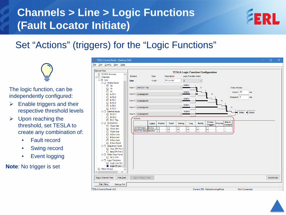
Channels > Line > Logic Functions(Fault Locator Initiate) Set “Actions” (triggers) for the “Logic Functions”
The logic function, can be independently configured: Enable triggers and their
respective threshold levels Upon reaching the
threshold, set TESLA to create any combination of:
• Fault record• Swing record• Event logging
Note: No trigger is set
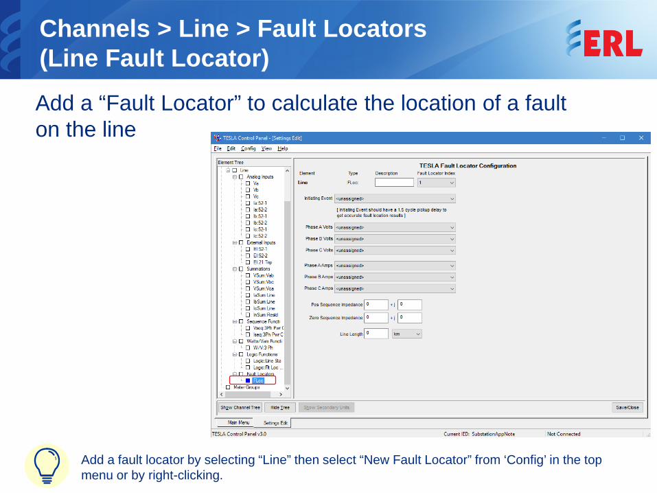
Channels > Line > Fault Locators(Line Fault Locator) Add a “Fault Locator” to calculate the location of a fault on the line
Add a fault locator by selecting “Line” then select “New Fault Locator” from ‘Config’ in the top menu or by right-clicking.
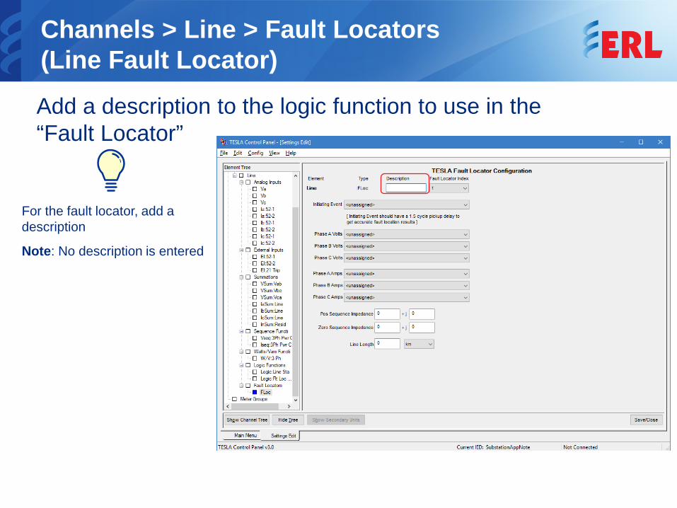
Channels > Line > Fault Locators(Line Fault Locator) Add a description to the logic function to use in the “Fault Locator”
For the fault locator, add a description
Note: No description is entered
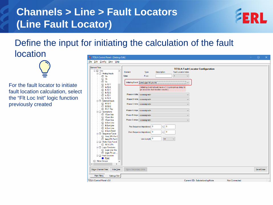
Channels > Line > Fault Locators(Line Fault Locator) Define the input for initiating the calculation of the fault location
For the fault locator to initiate fault location calculation, select the “Flt Loc Init” logic function previously created
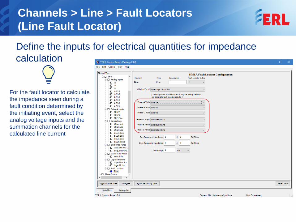
Channels > Line > Fault Locators(Line Fault Locator) Define the inputs for electrical quantities for impedance calculation
For the fault locator to calculate the impedance seen during a fault condition determined by the initiating event, select the analog voltage inputs and the summation channels for the calculated line current
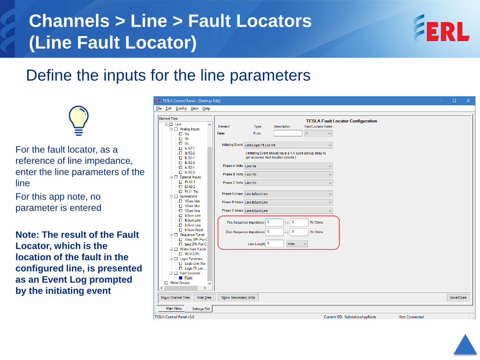
Channels > Line > Fault Locators(Line Fault Locator) Define the inputs for the line parameters
For the fault locator, as a reference of line impedance, enter the line parameters of the lineFor this app note, no parameter is entered
Note: The result of the Fault Locator, which is the location of the fault in the configured line, is presented as an Event Log prompted by the initiating event
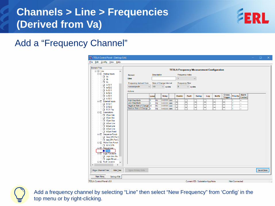
Channels > Line > Frequencies(Derived from Va) Add a “Frequency Channel”
Add a frequency channel by selecting “Line” then select “New Frequency” from ‘Config’ in the top menu or by right-clicking.
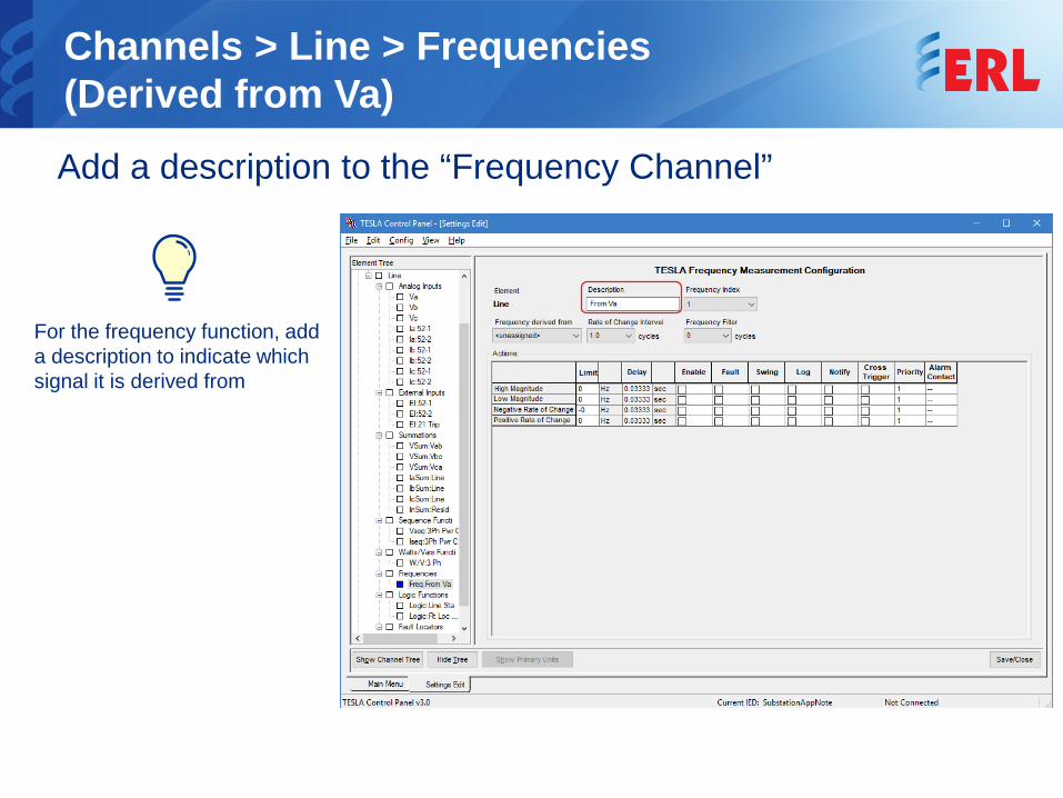
Channels > Line > Frequencies(Derived from Va) Add a description to the “Frequency Channel”
For the frequency function, add a description to indicate which signal it is derived from
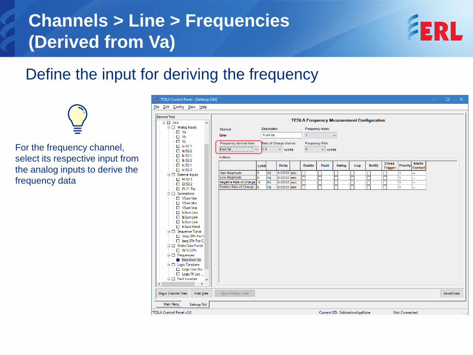
Channels > Line > Frequencies(Derived from Va)Define the input for deriving the frequency
For the frequency channel, select its respective input from the analog inputs to derive the frequency data
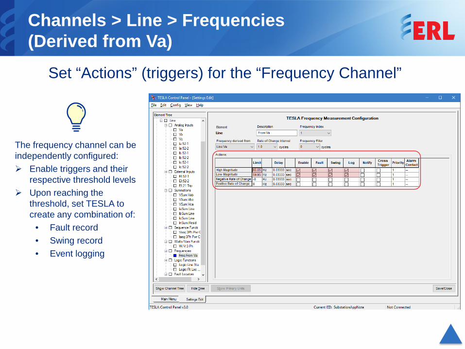
Channels > Line > Frequencies(Derived from Va)
Set “Actions” (triggers) for the “Frequency Channel”
The frequency channel can be independently configured: Enable triggers and their
respective threshold levels Upon reaching the
threshold, set TESLA to create any combination of:
• Fault record• Swing record• Event logging
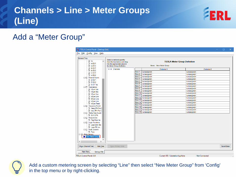
Channels > Line > Meter Groups(Line) Add a “Meter Group”
Add a custom metering screen by selecting “Line” then select “New Meter Group” from ‘Config’ in the top menu or by right-clicking.
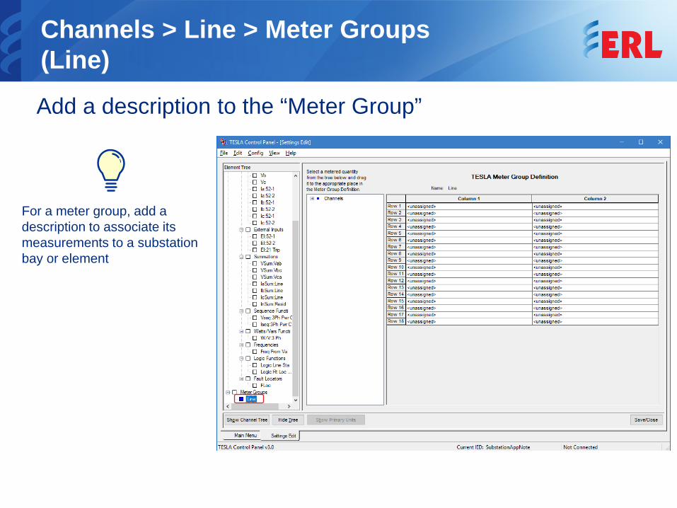
Channels > Line > Meter Groups(Line) Add a description to the “Meter Group”
For a meter group, add a description to associate its measurements to a substation bay or element
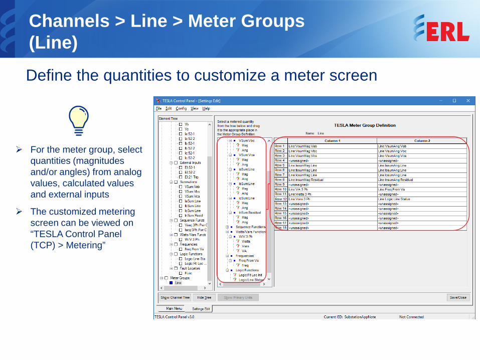
Channels > Line > Meter Groups(Line) Define the quantities to customize a meter screen
For the meter group, select quantities (magnitudes and/or angles) from analog values, calculated values and external inputs
The customized metering screen can be viewed on “TESLA Control Panel (TCP) > Metering”
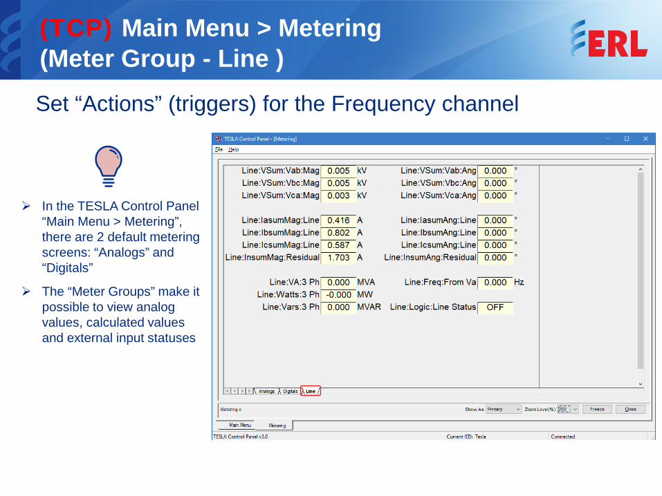
(TCP) Main Menu > Metering(Meter Group - Line )Set “Actions” (triggers) for the Frequency channel
In the TESLA Control Panel “Main Menu > Metering”, there are 2 default metering screens: “Analogs” and “Digitals”
The “Meter Groups” make it possible to view analog values, calculated values and external input statuses
PT S1
PT S2
9xAI
Line
CT 12
CT 11
CT 21
CT 2252
-252-1
21
Line Protection
Relay
3xEI
Current Module
Voltage Module
2x
Channels > Line > Inputs Summary
Select “Line” to see the summary of all configured channels

© ERLPhase Power Technologies Ltd. All Rights Reserved.
The specifications and product information contained in this document are subject to change without notice.In case of inconsistencies between documents, the version at www.erlphase.com will be considered correct.(D04542R01)
ERLPhase Technical SupportTel: +1 204-477-0591


![[Tesla Nickola] the Strange Life of Nikola Tesla(BookFi.org)](https://img.pdfslide.us/doc/110x75/55cf9cb0550346d033aab3ce/tesla-nickola-the-strange-life-of-nikola-teslabookfiorg.jpg)