Embed Size (px)
Citation preview
1
Power system and technical issues in South Korea
Prof. Jong-Keun Park
e-mail: [email protected]
School of Electrical Eng., Seoul National University, Seoul, 151-742, Korea
ABSTRACT
In South Korea, power transmission voltages are 345kV on major networks and
154kV or 66kV in local systems. Most 66kV lines are now either being removed or
replaced by higher voltage lines. As of 1999, the total length of transmission lines was
25,337 Circuit-km (C-km) and the total capacity of substation facilities was expanded to
120,257MVA.
765kV facilities are now being constructed, to be operated beginning in 2002, to
transmit electricity stably between large power generation plants and customer areas
due to the rapid increase in power demand in metropolitan areas.
The power system on Jeju island is now connected to the mainland via a 100km-
long submarine transmission system of HVDC (High Voltage Direct Current) cables.
Power transmission networks and substations are monitored and controlled by
SCADA (Supervisory Control and Data Acquisition) systems. These systems feature
T&D (Transmission & Distribution) facility improvements and control automation,
which includes installing more indoor and unmanned substations to enhance power
supply reliability.
To prevent the problematic rise in system voltage during off-peak times because
of the continuous expansion of the EHV (Extra High Voltage) system and underground
power lines, the power system in South Korea has installed shunt reactors. Also, static
condensers have been installed at 154kV substations in order to compensate for the
voltage drop of the system during heavy load periods. The regulation of a distribution
line voltage has adopted automatic ULTC (Under Load Tap Changer) operation in order
to maintain a constant voltage level.
Looking at the past 40 years, the domestic electric power industry,
encompassing all sectors of power generation, transmission, and distribution, has been
monopolized by the state-run Korea Electric Power Corporation (KEPCO). This
system had been justified due to the economic benefits; the required huge investments;
and the unique characteristics of electricity, such as simultaneous production and
2
consumption. However, with the recent development of small but high-efficiency
generators and information technology, the private sector investment in the electric
power industry can be facilitated, and the transaction of electricity is made possible.
This has led to the worldwide trend of the introduction of competition and privatization
of the electric power industry. The Korean government has decided to introduce
competition into the electric power industry sector to increase efficiency and
transparency, and to attract the participation of the private sector. Based on the
evaluation of KEPCO’s management system from 1994 to 1996 and incorporating
public opinions, the basic plan for the restructuring of the electric power industry was
announced in January 1999. According to the basic plan, the Korean government
established the new Act on Promotion of Restructuring of the Electric Power Industry
and revised the Electricity Business Law in December 2000. By December 2002, the
electric power market will be operated as the cost-based generation pool. The two-
way bidding pool (wholesale competition) will start in January 2003, and finally, retail
competition in January 2009.
Large-scale power plants have been constructed in the southern area of Korea,
and the metropolitan areas in central parts of Korea have consumed nearly of 42% of
the total electricity generated. Multiple connections were established to supply the
metropolitan areas, and a relatively large quantity of power flows northward. The
transmission capacity was increased, so that some buses must be operated separately,
and the reliability of the system has been taken into consideration in the planning stages
to improve system performance. The northward power flow should be restricted for
the security of the supply in a metropolitan area, and this constraint should be
investigated under various operating conditions.
The transient stability of the system should be examined under severe cases such
as a 3-phase fault and the simultaneous trip of a major two-transmission line. Some
simulations show that a fault on a major transmission line can cause system instability.
1. Statistics and restructuring of the electric power industries
1.1. History and present status
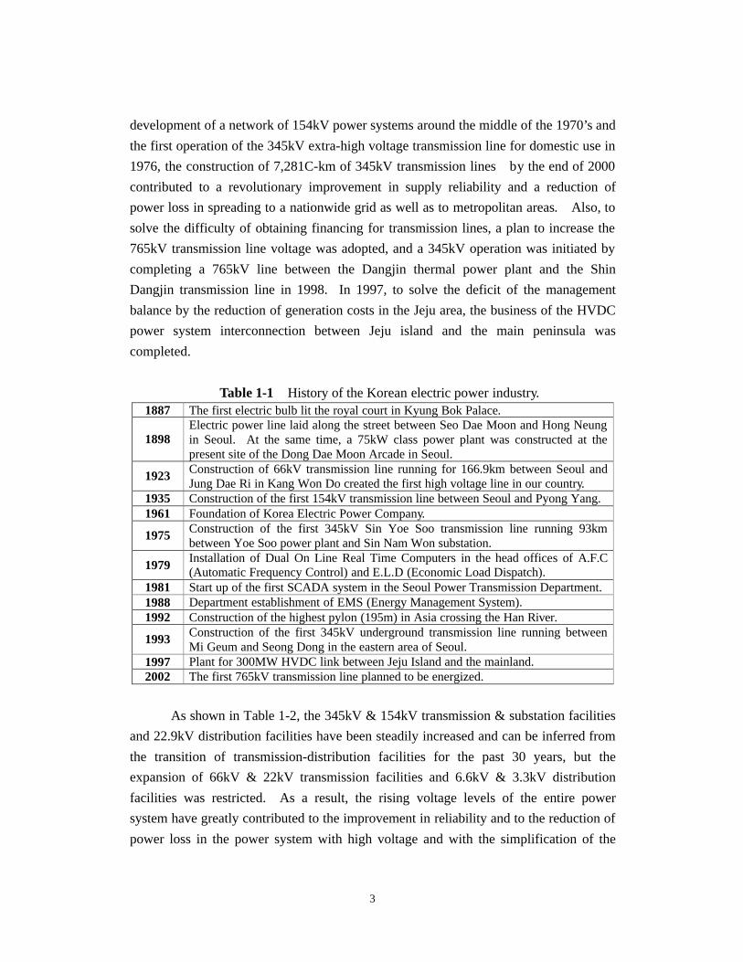
The history of the Korean electric power industry is shown in Table 1-1.
Korean power systems have been expanded and improved rapidly in quantity and
quality, complying with the requests of customers to follow the improvements in the
level of life styles and for the stimulation of industrial development. That is, since the
3
development of a network of 154kV power systems around the middle of the 1970’s and
the first operation of the 345kV extra-high voltage transmission line for domestic use in
1976, the construction of 7,281C-km of 345kV transmission lines by the end of 2000
contributed to a revolutionary improvement in supply reliability and a reduction of
power loss in spreading to a nationwide grid as well as to metropolitan areas. Also, to
solve the difficulty of obtaining financing for transmission lines, a plan to increase the
765kV transmission line voltage was adopted, and a 345kV operation was initiated by
completing a 765kV line between the Dangjin thermal power plant and the Shin
Dangjin transmission line in 1998. In 1997, to solve the deficit of the management
balance by the reduction of generation costs in the Jeju area, the business of the HVDC
power system interconnection between Jeju island and the main peninsula was
completed.
Table 1-1 History of the Korean electric power industry. 1887 The first electric bulb lit the royal court in Kyung Bok Palace.
1898 Electric power line laid along the street between Seo Dae Moon and Hong Neung in Seoul. At the same time, a 75kW class power plant was constructed at the present site of the Dong Dae Moon Arcade in Seoul.
1923 Construction of 66kV transmission line running for 166.9km between Seoul and Jung Dae Ri in Kang Won Do created the first high voltage line in our country.
1935 Construction of the first 154kV transmission line between Seoul and Pyong Yang. 1961 Foundation of Korea Electric Power Company.
1975 Construction of the first 345kV Sin Yoe Soo transmission line running 93km between Yoe Soo power plant and Sin Nam Won substation.
1979 Installation of Dual On Line Real Time Computers in the head offices of A.F.C (Automatic Frequency Control) and E.L.D (Economic Load Dispatch).
1981 Start up of the first SCADA system in the Seoul Power Transmission Department. 1988 Department establishment of EMS (Energy Management System). 1992 Construction of the highest pylon (195m) in Asia crossing the Han River.
1993 Construction of the first 345kV underground transmission line running between Mi Geum and Seong Dong in the eastern area of Seoul.
1997 Plant for 300MW HVDC link between Jeju Island and the mainland. 2002 The first 765kV transmission line planned to be energized.
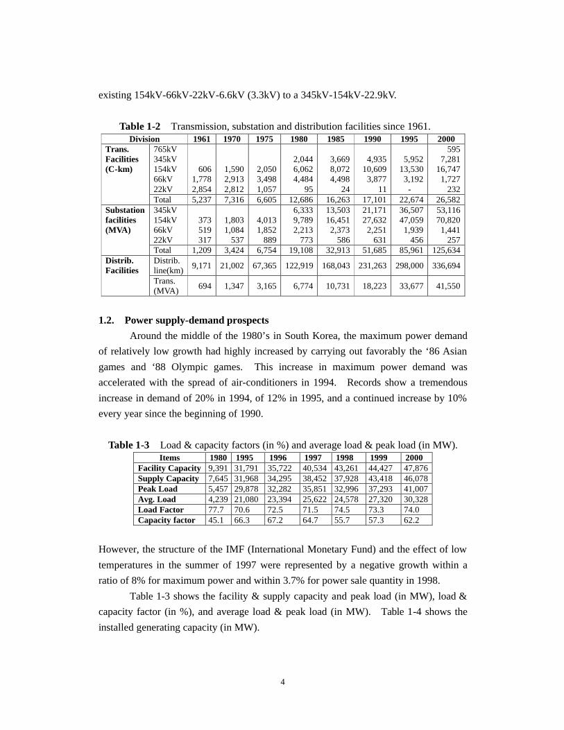
As shown in Table 1-2, the 345kV & 154kV transmission & substation facilities
and 22.9kV distribution facilities have been steadily increased and can be inferred from
the transition of transmission-distribution facilities for the past 30 years, but the
expansion of 66kV & 22kV transmission facilities and 6.6kV & 3.3kV distribution
facilities was restricted. As a result, the rising voltage levels of the entire power
system have greatly contributed to the improvement in reliability and to the reduction of
power loss in the power system with high voltage and with the simplification of the
4
existing 154kV-66kV-22kV-6.6kV (3.3kV) to a 345kV-154kV-22.9kV.
Table 1-2 Transmission, substation and distribution facilities since 1961. Division 1961 1970 1975 1980 1985 1990 1995 2000
765kV 345kV 154kV 66kV 22kV
606 1,778 2,854
1,590 2,913 2,812
2,050 3,498 1,057
2,044 6,062 4,484
95
3,669 8,072 4,498
24
4,935
10,609 3,877
11
5,952
13,530 3,192
-
595 7,281
16,747 1,727
232
Trans. Facilities (C-km)
Total 5,237 7,316 6,605 12,686 16,263 17,101 22,674 26,582 345kV 154kV 66kV 22kV
373 519 317
1,803 1,084
537
4,013 1,852
889
6,333 9,789 2,213
773
13,503 16,451 2,373
586
21,171 27,632
2,251 631
36,507 47,059 1,939
456
53,116 70,820
1,441 257
Substation facilities (MVA)
Total 1,209 3,424 6,754 19,108 32,913 51,685 85,961 125,634 Distrib. line(km)
9,171 21,002 67,365 122,919 168,043 231,263 298,000 336,694 Distrib. Facilities
Trans. (MVA)
694 1,347 3,165 6,774 10,731 18,223 33,677 41,550
1.2. Power supply-demand prospects
Around the middle of the 1980’s in South Korea, the maximum power demand
of relatively low growth had highly increased by carrying out favorably the ‘86 Asian
games and ‘88 Olympic games. This increase in maximum power demand was
accelerated with the spread of air-conditioners in 1994. Records show a tremendous
increase in demand of 20% in 1994, of 12% in 1995, and a continued increase by 10%
every year since the beginning of 1990.
Table 1-3 Load & capacity factors (in %) and average load & peak load (in MW). Items 1980 1995 1996 1997 1998 1999 2000
Facility Capacity 9,391 31,791 35,722 40,534 43,261 44,427 47,876 Supply Capacity 7,645 31,968 34,295 38,452 37,928 43,418 46,078 Peak Load 5,457 29,878 32,282 35,851 32,996 37,293 41,007 Avg. Load 4,239 21,080 23,394 25,622 24,578 27,320 30,328 Load Factor 77.7 70.6 72.5 71.5 74.5 73.3 74.0 Capacity factor 45.1 66.3 67.2 64.7 55.7 57.3 62.2
However, the structure of the IMF (International Monetary Fund) and the effect of low
temperatures in the summer of 1997 were represented by a negative growth within a
ratio of 8% for maximum power and within 3.7% for power sale quantity in 1998.
Table 1-3 shows the facility & supply capacity and peak load (in MW), load &
capacity factor (in %), and average load & peak load (in MW). Table 1-4 shows the
installed generating capacity (in MW).
5
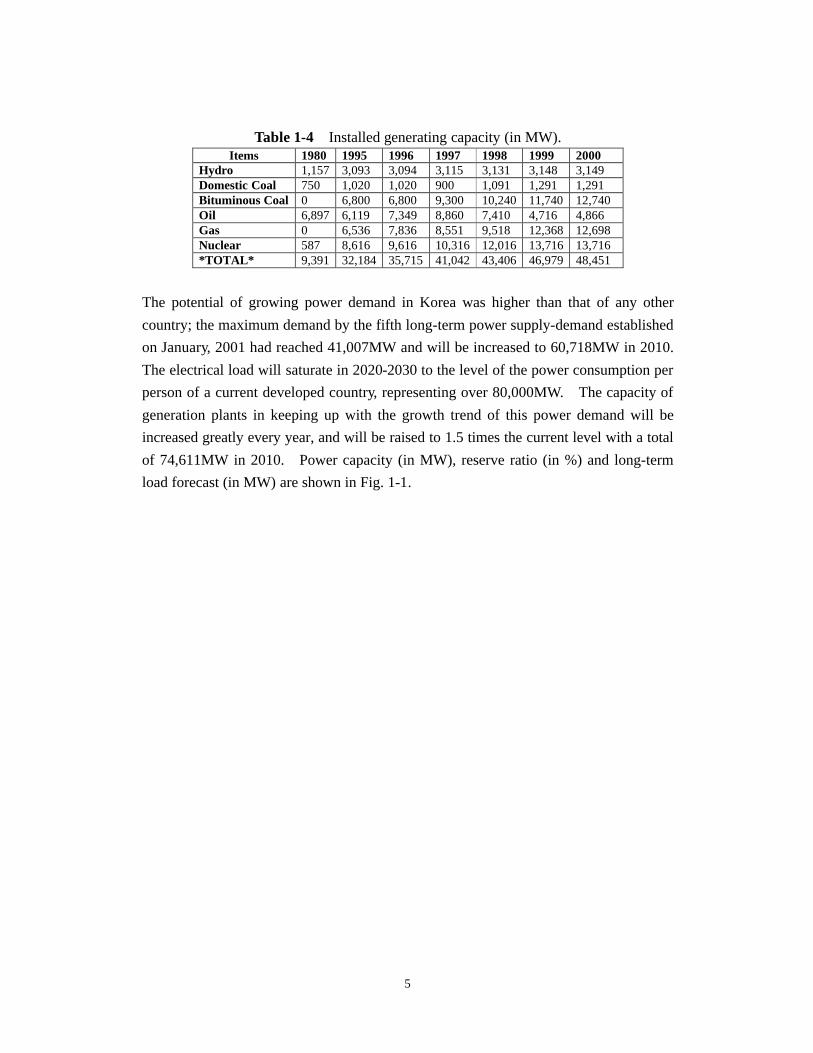
Table 1-4 Installed generating capacity (in MW). Items 1980 1995 1996 1997 1998 1999 2000
Hydro 1,157 3,093 3,094 3,115 3,131 3,148 3,149 Domestic Coal 750 1,020 1,020 900 1,091 1,291 1,291 Bituminous Coal 0 6,800 6,800 9,300 10,240 11,740 12,740 Oil 6,897 6,119 7,349 8,860 7,410 4,716 4,866 Gas 0 6,536 7,836 8,551 9,518 12,368 12,698 Nuclear 587 8,616 9,616 10,316 12,016 13,716 13,716 *TOTAL* 9,391 32,184 35,715 41,042 43,406 46,979 48,451
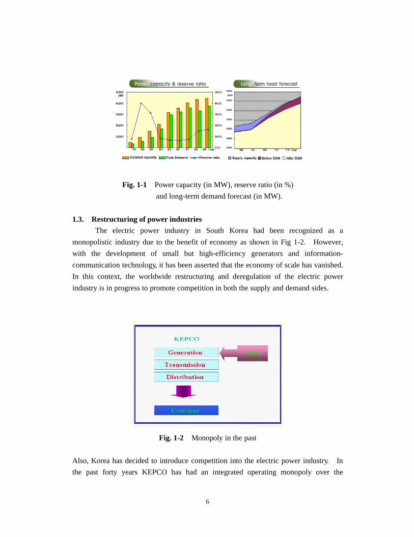
The potential of growing power demand in Korea was higher than that of any other
country; the maximum demand by the fifth long-term power supply-demand established
on January, 2001 had reached 41,007MW and will be increased to 60,718MW in 2010.
The electrical load will saturate in 2020-2030 to the level of the power consumption per
person of a current developed country, representing over 80,000MW. The capacity of
generation plants in keeping up with the growth trend of this power demand will be
increased greatly every year, and will be raised to 1.5 times the current level with a total
of 74,611MW in 2010. Power capacity (in MW), reserve ratio (in %) and long-term
load forecast (in MW) are shown in Fig. 1-1.
6
Fig. 1-1 Power capacity (in MW), reserve ratio (in %)
and long-term demand forecast (in MW).
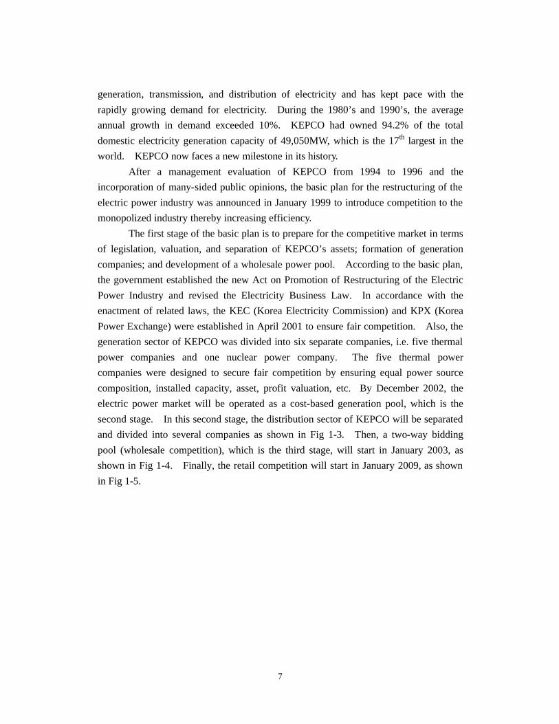
1.3. Restructuring of power industries
The electric power industry in South Korea had been recognized as a
monopolistic industry due to the benefit of economy as shown in Fig 1-2. However,
with the development of small but high-efficiency generators and information-
communication technology, it has been asserted that the economy of scale has vanished.
In this context, the worldwide restructuring and deregulation of the electric power
industry is in progress to promote competition in both the supply and demand sides.
Fig. 1-2 Monopoly in the past
Also, Korea has decided to introduce competition into the electric power industry. In
the past forty years KEPCO has had an integrated operating monopoly over the
7
generation, transmission, and distribution of electricity and has kept pace with the
rapidly growing demand for electricity. During the 1980’s and 1990’s, the average
annual growth in demand exceeded 10%. KEPCO had owned 94.2% of the total
domestic electricity generation capacity of 49,050MW, which is the 17th largest in the
world. KEPCO now faces a new milestone in its history.
After a management evaluation of KEPCO from 1994 to 1996 and the
incorporation of many-sided public opinions, the basic plan for the restructuring of the
electric power industry was announced in January 1999 to introduce competition to the
monopolized industry thereby increasing efficiency.
The first stage of the basic plan is to prepare for the competitive market in terms
of legislation, valuation, and separation of KEPCO’s assets; formation of generation
companies; and development of a wholesale power pool. According to the basic plan,
the government established the new Act on Promotion of Restructuring of the Electric
Power Industry and revised the Electricity Business Law. In accordance with the
enactment of related laws, the KEC (Korea Electricity Commission) and KPX (Korea
Power Exchange) were established in April 2001 to ensure fair competition. Also, the
generation sector of KEPCO was divided into six separate companies, i.e. five thermal
power companies and one nuclear power company. The five thermal power
companies were designed to secure fair competition by ensuring equal power source
composition, installed capacity, asset, profit valuation, etc. By December 2002, the
electric power market will be operated as a cost-based generation pool, which is the
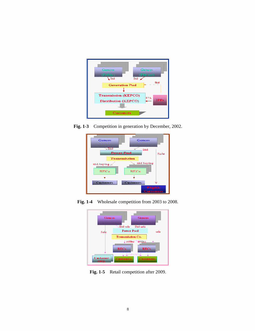
second stage. In this second stage, the distribution sector of KEPCO will be separated
and divided into several companies as shown in Fig 1-3. Then, a two-way bidding
pool (wholesale competition), which is the third stage, will start in January 2003, as
shown in Fig 1-4. Finally, the retail competition will start in January 2009, as shown
in Fig 1-5.
8
Fig. 1-3 Competition in generation by December, 2002.
Fig. 1-4 Wholesale competition from 2003 to 2008.
Fig. 1-5 Retail competition after 2009.
9
2. Transmission system
2.1. Transmission & substation systems
The power transmission system voltage levels in South Korea are 345kV, 154kV
and 66kV. First, 345kV transmission lines are made to form a bulk power transmission
system to transmit electric power among regions and to connect with external
transmission systems around small, medium, and large cities. Second, 154kV
transmission lines form a main branch system within a region, which is a power
distribution line in the center of large cities. Third, 66kV transmission lines will be
reduced gradually because of the improvement in transmission capacity and the
simplification of the power system. The transmission & substation divisions play the
role transmitting large power stably from power plants to load centers.
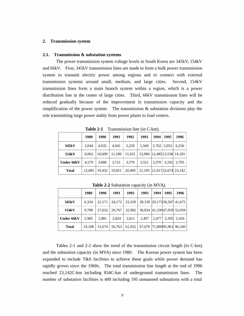
Table 2-1 Transmission line (in C-km).
1980 1990 1991 1992 1993 1994 1995 1996
345kV 2,044 4,935 4,941 5,259 5,560 5,762 5,952 6,256
154kV 6,062 10,609 11,189 11,631 12,084 12,485 13,530 14,181
Under 66kV 4,579 3,888 3,721 3,579 3,551 3,370 3,192 2,705
Total 12,685 19,432 19,851 20,469 21,195 21,617 22,674 23,142
Table 2-2 Substation capacity (in MVA).
1980 1990 1991 1992 1993 1994 1995 1996
345kV 6,334 21,171 24,172 23,339 28,339 29,173 36,507 41,675
154kV 9,789 27,632 29,767 32,982 36,834 41,239 47,059 52,059
Under 66kV 2,985 2,881 2,824 2,611 2,497 2,477 2,395 2,426
Total 19,108 51,674 56,763 61,932 67,670 71,889 85,961 96,160
Tables 2-1 and 2-2 show the trend of the transmission circuit length (in C-km)
and the substation capacity (in MVA) since 1980. The Korean power system has been
expanded to include T&S facilities to achieve these goals while power demand has
rapidly grown since the 1960s. The total transmission line length at the end of 1996
reached 23,142C-km including 834C-km of underground transmission lines. The
number of substation facilities is 400 including 195 unmanned substations with a total
10
of transformer capacity 96,160MVA. T&S facilities have become complex and large
in capacity along with increasing demand. There have been attempts to improve
system reliability and operate these facilities stably, and these have met with good
results, shown by the reduction of outage duration and faults, maintenance of regular
voltage levels, etc. The most vulnerable power system facilities continue to be
replaced. In the future, there will be introduced scientific supervision and diagnosis
equipment for T&S facilities, and new techniques are being developed and installed,
such as IDPCS (Integrated Digital Protection and Control System), and APRS
(Automatic Power Reconfiguration System), etc.
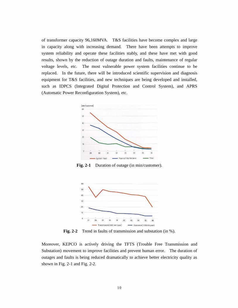
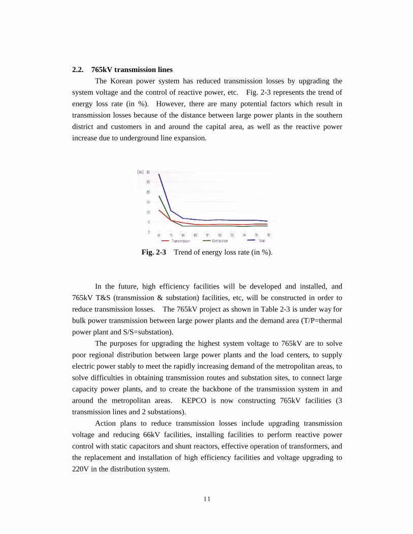
Fig. 2-1 Duration of outage (in min/customer).
Fig. 2-2 Trend in faults of transmission and substation (in %).
Moreover, KEPCO is actively driving the TFTS (Trouble Free Transmission and
Substation) movement to improve facilities and prevent human error. The duration of
outages and faults is being reduced dramatically to achieve better electricity quality as
shown in Fig. 2-1 and Fig. 2-2.
11
2.2. 765kV transmission lines
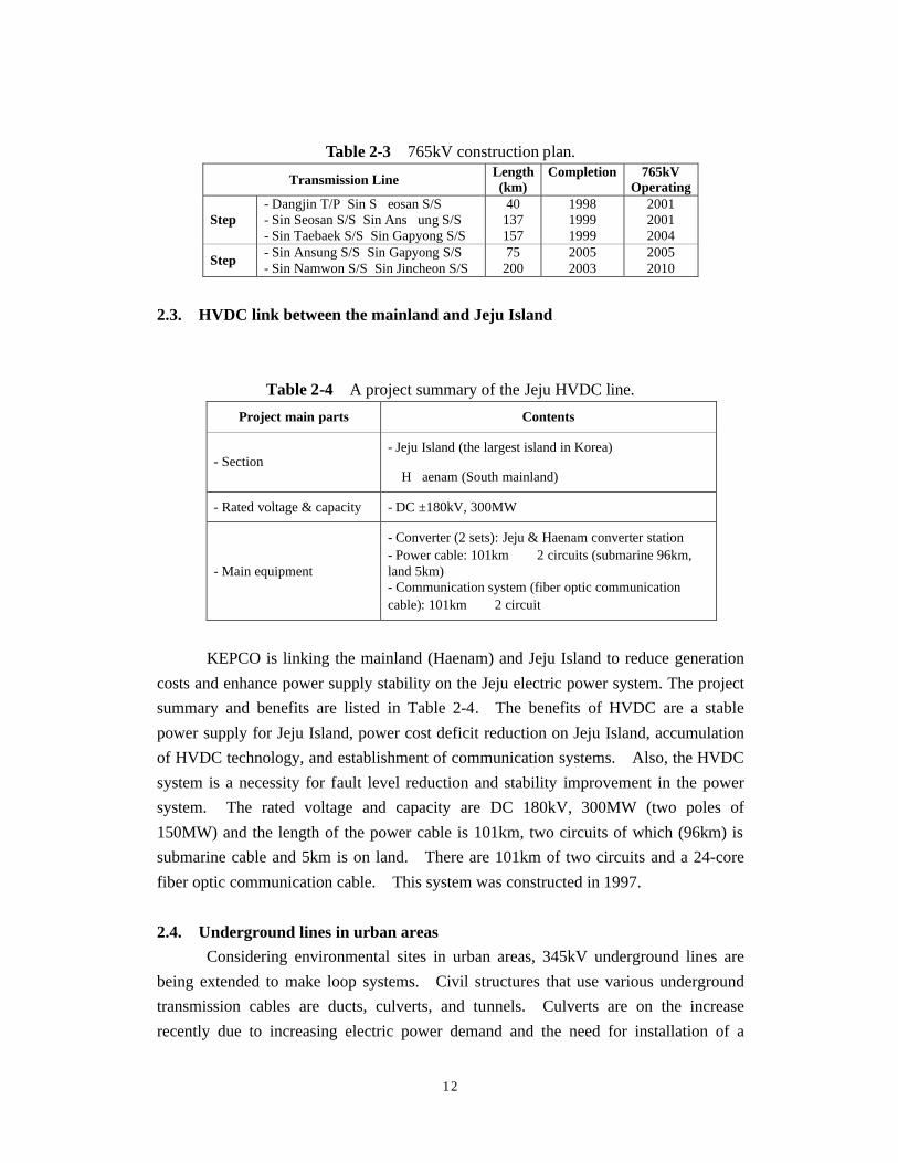
The Korean power system has reduced transmission losses by upgrading the
system voltage and the control of reactive power, etc. Fig. 2-3 represents the trend of
energy loss rate (in %). However, there are many potential factors which result in
transmission losses because of the distance between large power plants in the southern
district and customers in and around the capital area, as well as the reactive power
increase due to underground line expansion.
Fig. 2-3 Trend of energy loss rate (in %).
In the future, high efficiency facilities will be developed and installed, and
765kV T&S (transmission & substation) facilities, etc, will be constructed in order to
reduce transmission losses. The 765kV project as shown in Table 2-3 is under way for
bulk power transmission between large power plants and the demand area (T/P=thermal
power plant and S/S=substation).
The purposes for upgrading the highest system voltage to 765kV are to solve
poor regional distribution between large power plants and the load centers, to supply
electric power stably to meet the rapidly increasing demand of the metropolitan areas, to
solve difficulties in obtaining transmission routes and substation sites, to connect large
capacity power plants, and to create the backbone of the transmission system in and
around the metropolitan areas. KEPCO is now constructing 765kV facilities (3
transmission lines and 2 substations).
Action plans to reduce transmission losses include upgrading transmission
voltage and reducing 66kV facilities, installing facilities to perform reactive power
control with static capacitors and shunt reactors, effective operation of transformers, and
the replacement and installation of high efficiency facilities and voltage upgrading to
220V in the distribution system.
12
Table 2-3 765kV construction plan.
Transmission Line Length (km)
Completion
765kV Operating
Step � - Dangjin T/P � Sin S eosan S/S - Sin Seosan S/S � Sin Ans ung S/S - Sin Taebaek S/S � Sin Gapyong S/S
40 137 157
1998 1999 1999
2001 2001 2004
Step � - Sin Ansung S/S � Sin Gapyong S/S - Sin Namwon S/S � Sin Jincheon S/S
75 200
2005 2003
2005 2010
2.3. HVDC link between the mainland and Jeju Island
Table 2-4 A project summary of the Jeju HVDC line.
Project main parts Contents
- Section - Jeju Island (the largest island in Korea)
�H aenam (South mainland)
- Rated voltage & capacity - DC ±180kV, 300MW
- Main equipment
- Converter (2 sets): Jeju & Haenam converter station - Power cable: 101km � 2 circuits (submarine 96km, land 5km) - Communication system (fiber optic communication cable): 101km � 2 circuit
KEPCO is linking the mainland (Haenam) and Jeju Island to reduce generation
costs and enhance power supply stability on the Jeju electric power system. The project
summary and benefits are listed in Table 2-4. The benefits of HVDC are a stable
power supply for Jeju Island, power cost deficit reduction on Jeju Island, accumulation
of HVDC technology, and establishment of communication systems. Also, the HVDC
system is a necessity for fault level reduction and stability improvement in the power
system. The rated voltage and capacity are DC 180kV, 300MW (two poles of
150MW) and the length of the power cable is 101km, two circuits of which (96km) is
submarine cable and 5km is on land. There are 101km of two circuits and a 24-core
fiber optic communication cable. This system was constructed in 1997.
2.4. Underground lines in urban areas
Considering environmental sites in urban areas, 345kV underground lines are
being extended to make loop systems. Civil structures that use various underground
transmission cables are ducts, culverts, and tunnels. Culverts are on the increase
recently due to increasing electric power demand and the need for installation of a
13
number of cables in the same route. Especially in the downtown areas, tunnels are
increasing due to local government needs to obtain roads. Since 1995, XLPE (Cross-
Linked Polyethlene) cable has been used exclusively for 154kV underground
transmission facilities, with some exceptions (connection to existing OF cable), because
of environmental considerations and low operating costs due to the simplicity of the
cable system in comparison with traditional oil filled cables. In the future, XLPE
cable will be used for 345kV, and local cable makers are actively engaged in the
development of the 345kV XLPE cable.
2.5. Transmission planning
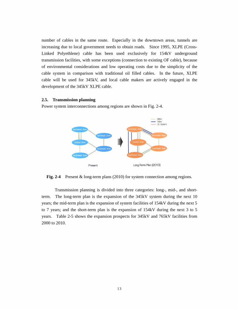
Power system interconnections among regions are shown in Fig. 2-4.
Fig. 2-4 Present & long-term plans (2010) for system connection among regions.
Transmission planning is divided into three categories: long-, mid-, and short-
term. The long-term plan is the expansion of the 345kV system during the next 10
years; the mid-term plan is the expansion of system facilities of 154kV during the next 5
to 7 years; and the short-term plan is the expansion of 154kV during the next 3 to 5
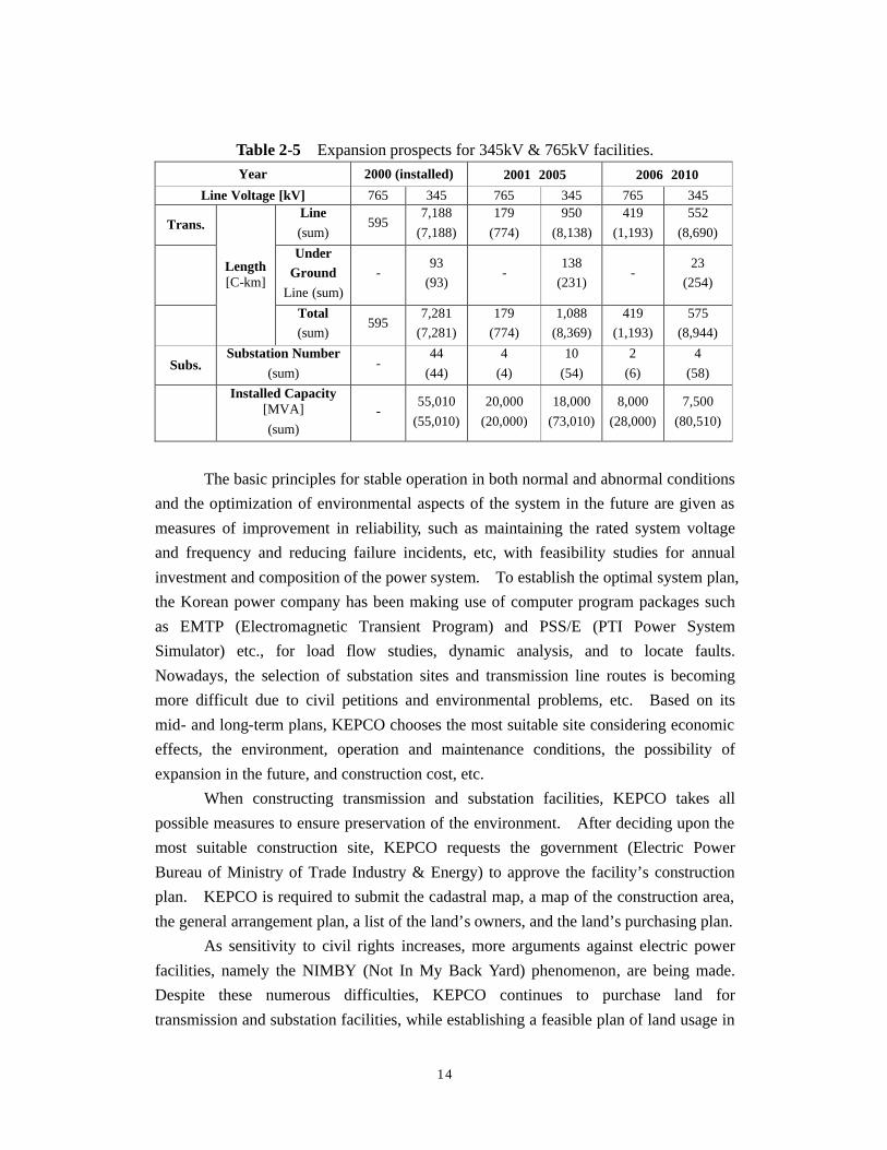
years. Table 2-5 shows the expansion prospects for 345kV and 765kV facilities from
2000 to 2010.
14
Table 2-5 Expansion prospects for 345kV & 765kV facilities.
Year 2000 (installed) 2001∼∼2005 2006∼∼2010
Line Voltage [kV] 765 345 765 345 765 345
Trans. Line
(sum) 595
7,188
(7,188)
179
(774)
950
(8,138)
419
(1,193)
552
(8,690)
Under Ground
Line (sum)
- 93
(93) -
138
(231) -
23
(254)
Length [C-km]
Total (sum)
595 7,281
(7,281)
179
(774)
1,088
(8,369)
419
(1,193)
575
(8,944)
Subs. Substation Number
(sum) -
44
(44)
4
(4)
10
(54)
2
(6)
4
(58)
Installed Capacity [MVA]
(sum) -
55,010
(55,010)
20,000
(20,000)
18,000
(73,010)
8,000
(28,000)
7,500
(80,510)
The basic principles for stable operation in both normal and abnormal conditions
and the optimization of environmental aspects of the system in the future are given as
measures of improvement in reliability, such as maintaining the rated system voltage
and frequency and reducing failure incidents, etc, with feasibility studies for annual
investment and composition of the power system. To establish the optimal system plan,
the Korean power company has been making use of computer program packages such
as EMTP (Electromagnetic Transient Program) and PSS/E (PTI Power System
Simulator) etc., for load flow studies, dynamic analysis, and to locate faults.
Nowadays, the selection of substation sites and transmission line routes is becoming
more difficult due to civil petitions and environmental problems, etc. Based on its
mid- and long-term plans, KEPCO chooses the most suitable site considering economic
effects, the environment, operation and maintenance conditions, the possibility of
expansion in the future, and construction cost, etc.
When constructing transmission and substation facilities, KEPCO takes all
possible measures to ensure preservation of the environment. After deciding upon the
most suitable construction site, KEPCO requests the government (Electric Power
Bureau of Ministry of Trade Industry & Energy) to approve the facility’s construction
plan. KEPCO is required to submit the cadastral map, a map of the construction area,
the general arrangement plan, a list of the land’s owners, and the land’s purchasing plan.
As sensitivity to civil rights increases, more arguments against electric power
facilities, namely the NIMBY (Not In My Back Yard) phenomenon, are being made.
Despite these numerous difficulties, KEPCO continues to purchase land for
transmission and substation facilities, while establishing a feasible plan of land usage in
15
conjunction with the land’s owners. That plan of land usage broadly covers
environmental issues and regional society development, as well as fundamental land
usage.
Transmission lines will be continuously expanded with multi-conductors, which
may be 2 or 4 bundles of ACSR (Aluminum Conductor Steel Reinforced) 480mm2 per
single phase in 345kV lines, 2 bundles of ACSR 410mm2 per single phase in 154kV
trunk lines and single or doubles of ACSR 410mm2 or 330mm2 per single phase in
154kV branch lines.
2.6. SCADA
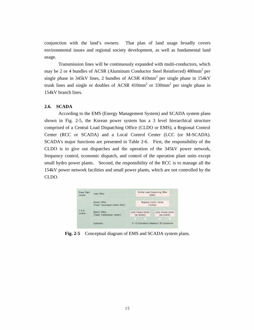
According to the EMS (Energy Management System) and SCADA system plans
shown in Fig. 2-5, the Korean power system has a 3 level hierarchical structure
comprised of a Central Load Dispatching Office (CLDO or EMS), a Regional Control
Center (RCC or SCADA) and a Local Control Center (LCC (or M-SCADA).
SCADA’s major functions are presented in Table 2-6. First, the responsibility of the
CLDO is to give out dispatches and the operation of the 345kV power network,
frequency control, economic dispatch, and control of the operation plant units except
small hydro power plants. Second, the responsibility of the RCC is to manage all the
154kV power network facilities and small power plants, which are not controlled by the
CLDO.
Fig. 2-5 Conceptual diagram of EMS and SCADA system plans.
16
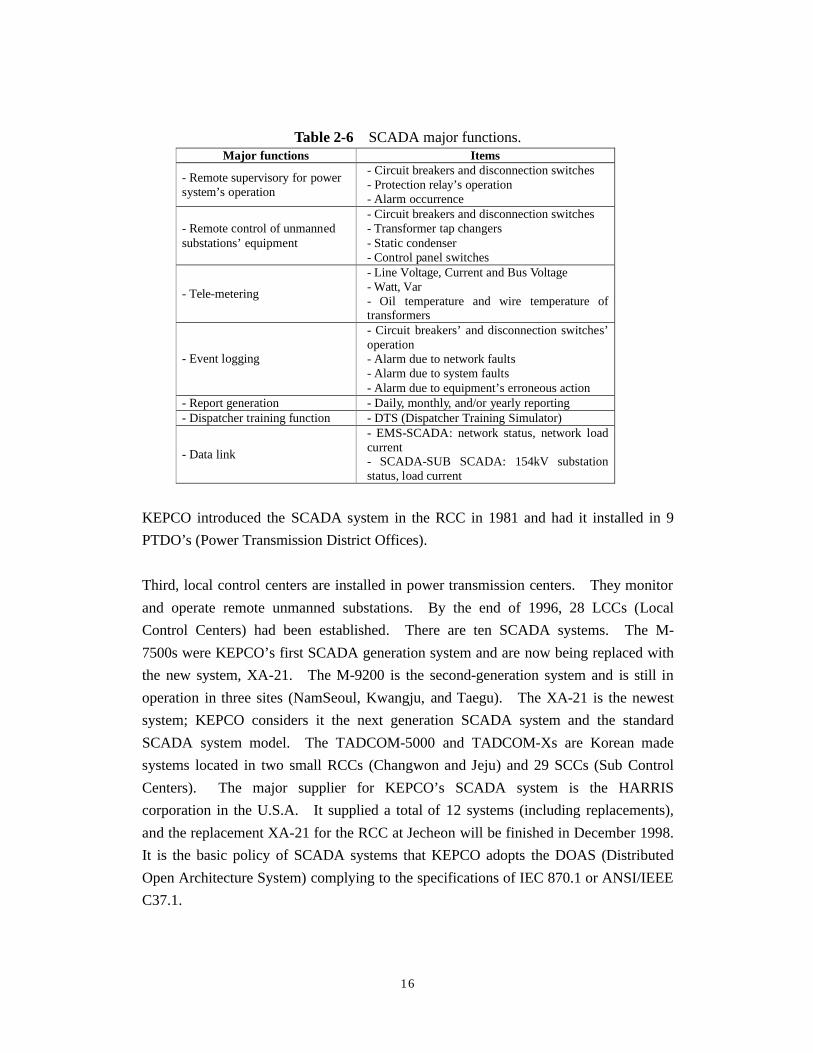
Table 2-6 SCADA major functions. Major functions Items
- Remote supervisory for power system’s operation
- Circuit breakers and disconnection switches - Protection relay’s operation - Alarm occurrence
- Remote control of unmanned substations’ equipment
- Circuit breakers and disconnection switches - Transformer tap changers - Static condenser - Control panel switches
- Tele-metering
- Line Voltage, Current and Bus Voltage - Watt, Var - Oil temperature and wire temperature of transformers
- Event logging
- Circuit breakers’ and disconnection switches’ operation - Alarm due to network faults - Alarm due to system faults - Alarm due to equipment’s erroneous action
- Report generation - Daily, monthly, and/or yearly reporting - Dispatcher training function - DTS (Dispatcher Training Simulator)
- Data link
- EMS-SCADA: network status, network load current - SCADA-SUB SCADA: 154kV substation status, load current
KEPCO introduced the SCADA system in the RCC in 1981 and had it installed in 9
PTDO’s (Power Transmission District Offices).
Third, local control centers are installed in power transmission centers. They monitor
and operate remote unmanned substations. By the end of 1996, 28 LCCs (Local
Control Centers) had been established. There are ten SCADA systems. The M-
7500s were KEPCO’s first SCADA generation system and are now being replaced with
the new system, XA-21. The M-9200 is the second-generation system and is still in
operation in three sites (NamSeoul, Kwangju, and Taegu). The XA-21 is the newest
system; KEPCO considers it the next generation SCADA system and the standard
SCADA system model. The TADCOM-5000 and TADCOM-Xs are Korean made
systems located in two small RCCs (Changwon and Jeju) and 29 SCCs (Sub Control
Centers). The major supplier for KEPCO’s SCADA system is the HARRIS
corporation in the U.S.A. It supplied a total of 12 systems (including replacements),
and the replacement XA-21 for the RCC at Jecheon will be finished in December 1998.
It is the basic policy of SCADA systems that KEPCO adopts the DOAS (Distributed
Open Architecture System) complying to the specifications of IEC 870.1 or ANSI/IEEE
C37.1.
17
3. Technical issues
The technical issues of the Korean power system are fault current problems,
secure system operation, voltage regulation problems in metropolitan areas, and
transient stability problems.
3.1. Fault current problem
As power plants become bigger and power systems are multiply connected, the
fault current exceeds the limit of circuit breaker capacity. So, the separation of buses
is inevitable—which lowers system reliability. Presently (March 2001), 6 345kV
substation are operated in separation and 50 154kV substation and transmission lines
are in separation, but as the system load increases, we must check the limit of the
present state. So, tests are performed to investigate the limit of the fault current. The
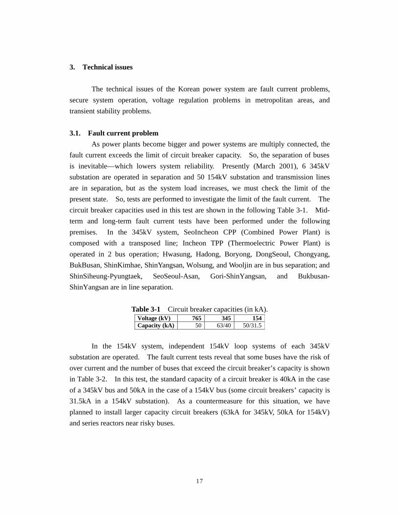
circuit breaker capacities used in this test are shown in the following Table 3-1. Mid-
term and long-term fault current tests have been performed under the following
premises. In the 345kV system, SeoIncheon CPP (Combined Power Plant) is
composed with a transposed line; Incheon TPP (Thermoelectric Power Plant) is
operated in 2 bus operation; Hwasung, Hadong, Boryong, DongSeoul, Chongyang,
BukBusan, ShinKimhae, ShinYangsan, Wolsung, and Wooljin are in bus separation; and
ShinSiheung-Pyungtaek, SeoSeoul-Asan, Gori-ShinYangsan, and Bukbusan-
ShinYangsan are in line separation.
Table 3-1 Circuit breaker capacities (in kA). Voltage (kV) 765 345 154 Capacity (kA) 50 63/40 50/31.5
In the 154kV system, independent 154kV loop systems of each 345kV
substation are operated. The fault current tests reveal that some buses have the risk of
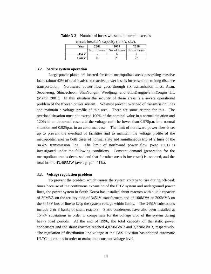
over current and the number of buses that exceed the circuit breaker’s capacity is shown
in Table 3-2. In this test, the standard capacity of a circuit breaker is 40kA in the case
of a 345kV bus and 50kA in the case of a 154kV bus (some circuit breakers’ capacity is
31.5kA in a 154kV substation). As a countermeasure for this situation, we have
planned to install larger capacity circuit breakers (63kA for 345kV, 50kA for 154kV)
and series reactors near risky buses.
18
Table 3-2 Number of buses whose fault current exceeds
circuit breaker’s capacity (in kA, site). Year 2001 2005 2010
No. of buses No. of buses No. of buses 345kV - 6 7 154kV 8 25 27
3.2. Secure system operation
Large power plants are located far from metropolitan areas possessing massive
loads (about 42% of total loads), so reactive power loss is increased due to long distance
transportation. Northward power flow goes through six transmission lines: Asan,
Seocheong, ShinJecheon, ShinYongin, Wooljung, and ShinDangjin-ShinYongin T/L
(March 2001). In this situation the security of these areas is a severe operational
problem of the Korean power system. We must prevent overload of transmission lines
and maintain a voltage profile of this area. There are some criteria for this. The
overload situation must not exceed 100% of the nominal value in a normal situation and
120% in an abnormal case, and the voltage can’t be lower than 0.975p.u. in a normal
situation and 0.925p.u. in an abnormal case. The limit of northward power flow is set
up to prevent the overload of facilities and to maintain the voltage profile of the
metropolitan area in both cases of normal state and simultaneous trip of 2 lines of the
345kV transmission line. The limit of northward power flow (year 2001) is
investigated under the following conditions. Constant demand (generation for the
metropolitan area is decreased and that for other areas is increased) is assumed, and the
total load is 43,465MW (average p.f.: 91%).
3.3. Voltage regulation problem
To prevent the problem which causes the system voltage to rise during off-peak
times because of the continuous expansion of the EHV system and underground power
lines, the power system in South Korea has installed shunt reactors with a unit capacity
of 30MVA on the tertiary side of 345kV transformers and of 100MVA or 200MVA on
the 345kV bus or line to keep the system voltage within limits. The 345kV substations
include 2 or 3 banks of shunt reactors. Static condensers have also been installed at
154kV substations in order to compensate for the voltage drop of the system during
heavy load periods. At the end of 1996, the total capacity of the static power
condensers and the shunt reactors reached 4,870MVAR and 3,270MVAR, respectively.
The regulation of distribution line voltage at the T&S Division has adopted automatic
ULTC operations in order to maintain a constant voltage level.
19
3.4. Transient stability
The most typical stability problem of power systems is transient stability. We
investigate the transient stability of the Korean power system under the following
premises. Faults assumed in this test are bus 3-phase shorts and simultaneous trip of
two lines of the main 345kV T/L. Fault duration time is set to 6 cycles and simulation
time for transient stability is 5 sec. The results of simulation for transient stability are
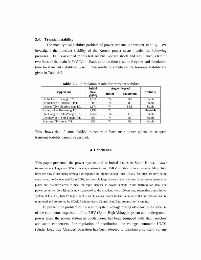
given in Table 3-5.
Table 3-5 Simulation results for transient stability. Angle (degree)
Tripped line Initial flow
(MW) Initial Maximum Stability
SeoIncheon ~ Yangju T/L 1,611 74 100 Stable SeoIncheon ~ Incheon TP T/L 808 74 85 Stable Incheon TP ~ ShinIncheon T/L 1,171 74 86.5 Stable Pyungtack ~ Hwaseong T/L 1,139 74 Unstable ShinDangjin ~ ShinYongin T/L 1,260 74 115 Stable Cheongwon ~ ShinYongin T/L 585 74 87 Stable Boryong TP ~ Asan T/L 958 74 99 Stable
This shows that if some 345kV transmission lines near power plants are tripped,
transient stability cannot be assured.
4. Conclusion
This paper presented the power system and technical issues in South Korea. Power
transmission voltages are 345kV on major networks and 154kV or 66kV in local systems. Most 66kV
lines are now either being removed or replaced by higher voltage lines. 765kV facilities are now being
constructed, to be operated from 2002, to transmit large power stably between large-power generation
plants and customer areas to meet the rapid increase in power demand in the metropolitan area. The
power system on Jeju Island is now connected to the mainland via a 100km-long submarine transmission
system of HVDC (High Voltage Direct Current) cables. Power transmission networks and substations are
monitored and controlled by SCADA (Supervisory Control And Data Acquisition) systems.
To prevent the problem of the rise in system voltage during off-peak times because
of the continuous expansion of the EHV (Extra High Voltage) system and underground
power lines, the power system in South Korea has been equipped with shunt reactors
and static condensers. For regulation of distribution line voltage, automatic ULTC
(Under Load Tap Changer) operation has been adopted to maintain a constant voltage
20
level.
The Korean government has decided to introduce competition into the electric
power industry sector to increase efficiency and transparency and to attract the
participation of the private sector. Using the evaluation of KEPCO’s management
system from 1994 to 1996 and incorporating public opinions, the basic plan for the
restructuring of the electric power industry was announced in January 1999. In
accordance with this basic plan, the Korean government established the new Act on
Promotion of Restructuring of the Electric Power Industry and revised the Electricity
Business Law in December 2000. By December 2002, the electric power market will be
operated through a cost-based generation pool. The two-way bidding pool (wholesale
competition) will start in January 2003, and finally retail competition will begin in
January 2009.
Large-scale power plants have been constructed in the southern area of Korea. The
metropolitan area in central parts of Korea has consumed nearly of 42% of the total
electricity generated. Multiple routes of connection networks were established to supply
the metropolitan area, and large-scale power flows relatively northward. The size of the
transmission system was increased, so that some buses must be operated separately. The
reliability of the system has been taken into consideration in the planning stages to
improve system reliability. The northward power flow should be restricted for the
security of the supply in a metropolitan area, and this constraint should be investigated
under various operating conditions.
The transient stability of the system should be examined under severe cases such as
3-phase fault and the simultaneous trip of major two-transmission line. Some
simulations show that a fault on a major transmission line can cause system instability.