Embed Size (px)
Citation preview
Power System Analysis
ELE401
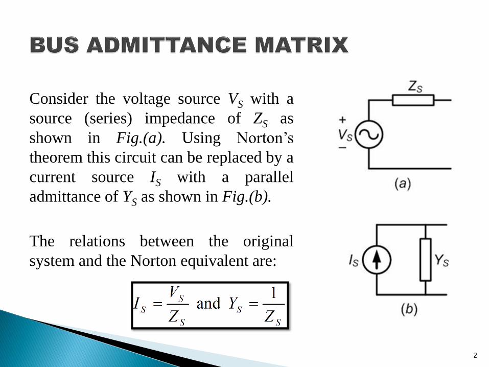
Consider the voltage source VS with a
source (series) impedance of ZS as
shown in Fig.(a). Using Norton’s
theorem this circuit can be replaced by a
current source IS with a parallel
admittance of YS as shown in Fig.(b).
The relations between the original
system and the Norton equivalent are:
2
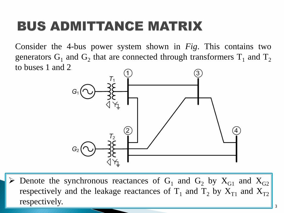
Consider the 4-bus power system shown in Fig. This contains two
generators G1 and G2 that are connected through transformers T1 and T2
to buses 1 and 2.
Denote the synchronous reactances of G1 and G2 by XG1 and XG2
respectively and the leakage reactances of T1 and T2 by XT1 and XT2
respectively. 3
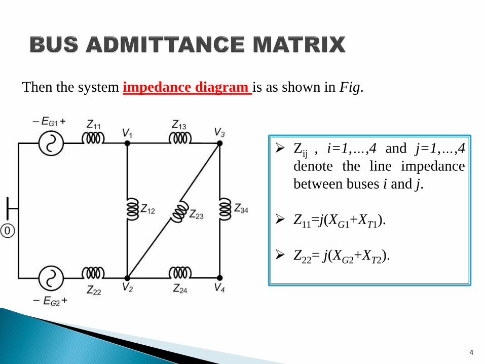
Zij , i=1,…,4 and j=1,…,4
denote the line impedance
between buses i and j.
Z11=j(XG1+XT1).
Z22= j(XG2+XT2).
Then the system impedance diagram is as shown in Fig.
4
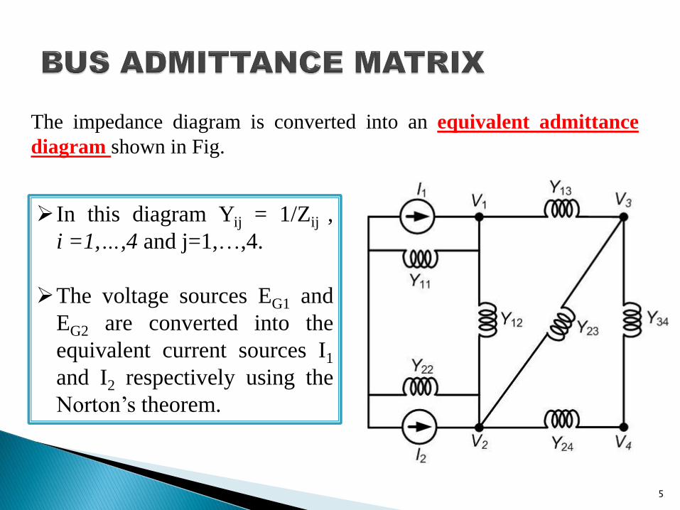
In this diagram Yij = 1/Zij ,
i =1,…,4 and j=1,…,4.
The voltage sources EG1 and
EG2 are converted into the
equivalent current sources I1
and I2 respectively using the
Norton’s theorem.
The impedance diagram is converted into an equivalent admittance
diagram shown in Fig.
5
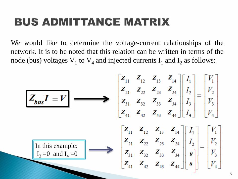
We would like to determine the voltage-current relationships of the
network. It is to be noted that this relation can be written in terms of the
node (bus) voltages V1 to V4 and injected currents I1 and I2 as follows:
In this example:
I3 =0 and I4 =0
6
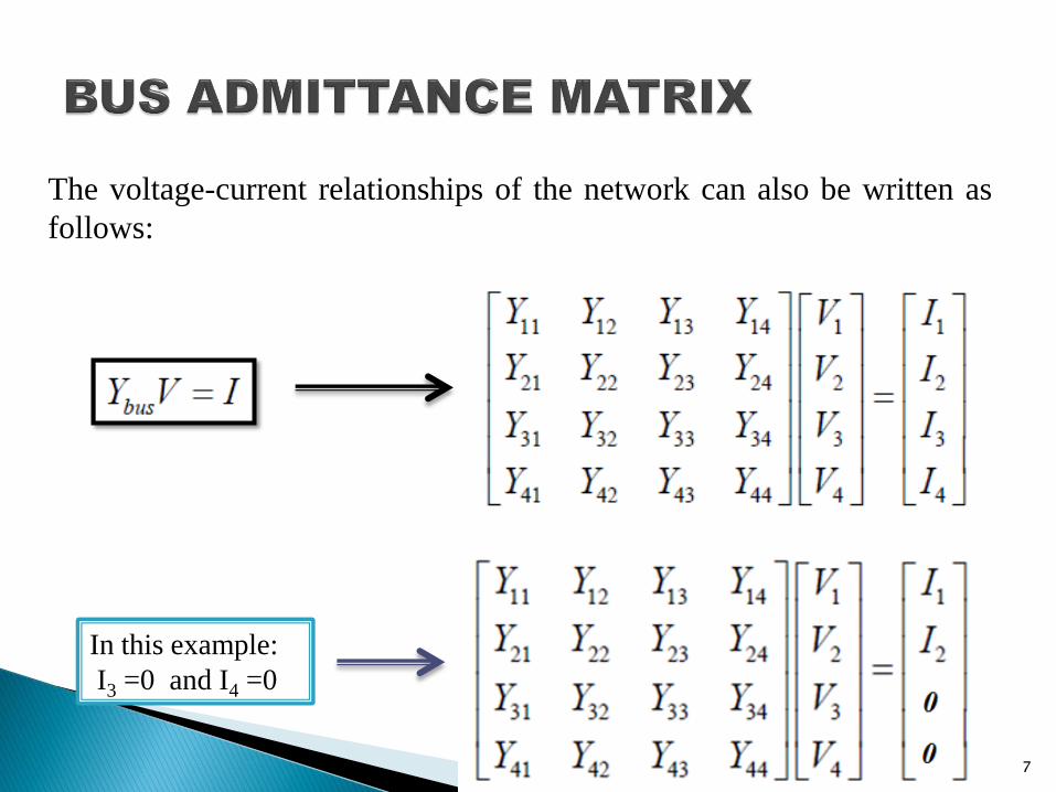
The voltage-current relationships of the network can also be written as
follows:
In this example:
I3 =0 and I4 =0
7
Zbus is called Bus Impedance Matrix and Ybus is called Bus
Admittance Matrix.
It is too difficult to write Zbus of n-bus power system using the
impedance diagram, but there is a simple way to write Ybus of
power system using the admittance diagram.
To find Zbus of n-bus power system you should:
1) Draw admittance diagram of power system
2) Calculate Ybus of power system
3) Calculate the inverse of Ybus : (Zbus =Ybus -1
)
8
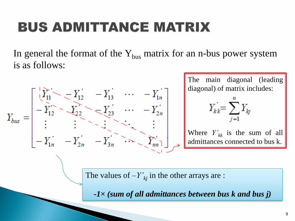
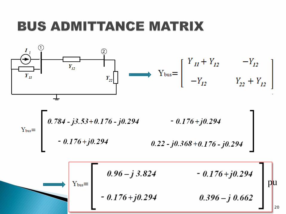
In general the format of the Ybus matrix for an n-bus power system
is as follows:
The main diagonal (leading
diagonal) of matrix includes:
Where Y’kk is the sum of all
admittances connected to bus k.
The values of –Y’kj in the other arrays are :
-1× (sum of all admittances between bus k and bus j)
9
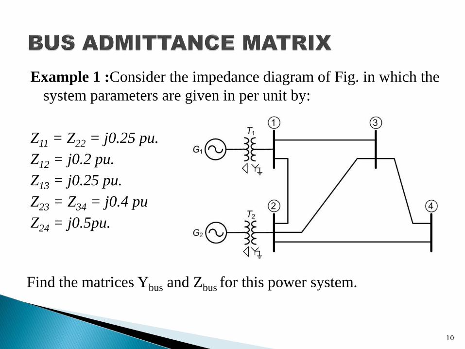
Example 1 :Consider the impedance diagram of Fig. in which the
system parameters are given in per unit by:
Z11 = Z22 = j0.25 pu.
Z12 = j0.2 pu.
Z13 = j0.25 pu.
Z23 = Z34 = j0.4 pu
Z24 = j0.5pu.
Find the matrices Ybus and Zbus for this power system.
10
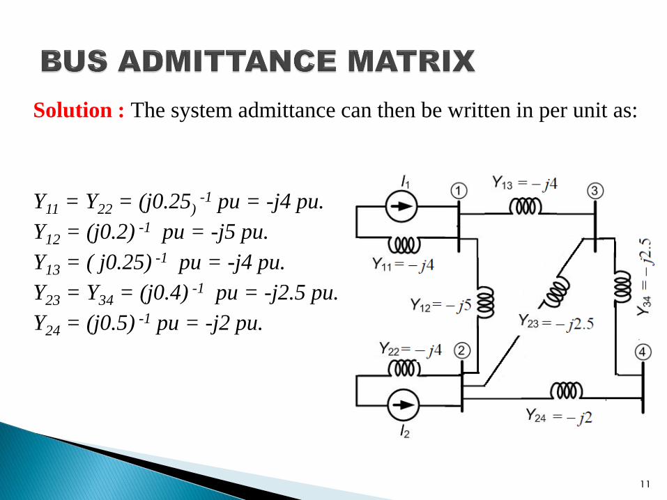
Solution : The system admittance can then be written in per unit as:
Y11 = Y22 = (j0.25) -1 pu = -j4 pu.
Y12 = (j0.2) -1 pu = -j5 pu.
Y13 = ( j0.25) -1 pu = -j4 pu.
Y23 = Y34 = (j0.4) -1 pu = -j2.5 pu.
Y24 = (j0.5) -1 pu = -j2 pu.
11
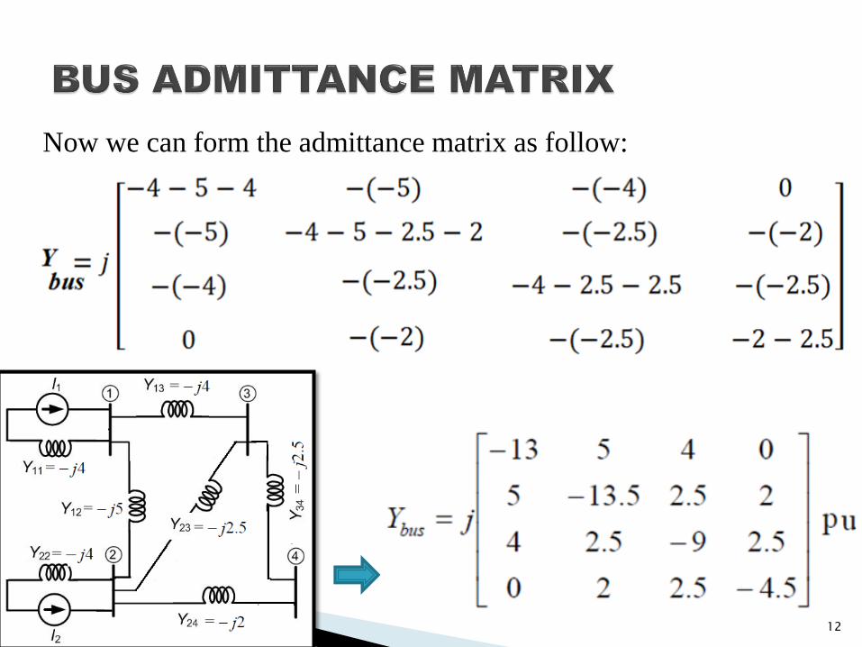
Now we can form the admittance matrix as follow:
12
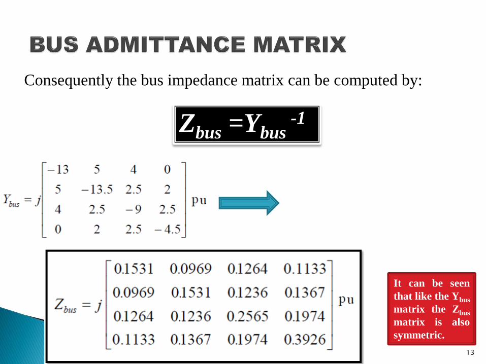
Consequently the bus impedance matrix can be computed by:
Zbus =Ybus -1
It can be seen
that like the Ybus
matrix the Zbus
matrix is also
symmetric.
13
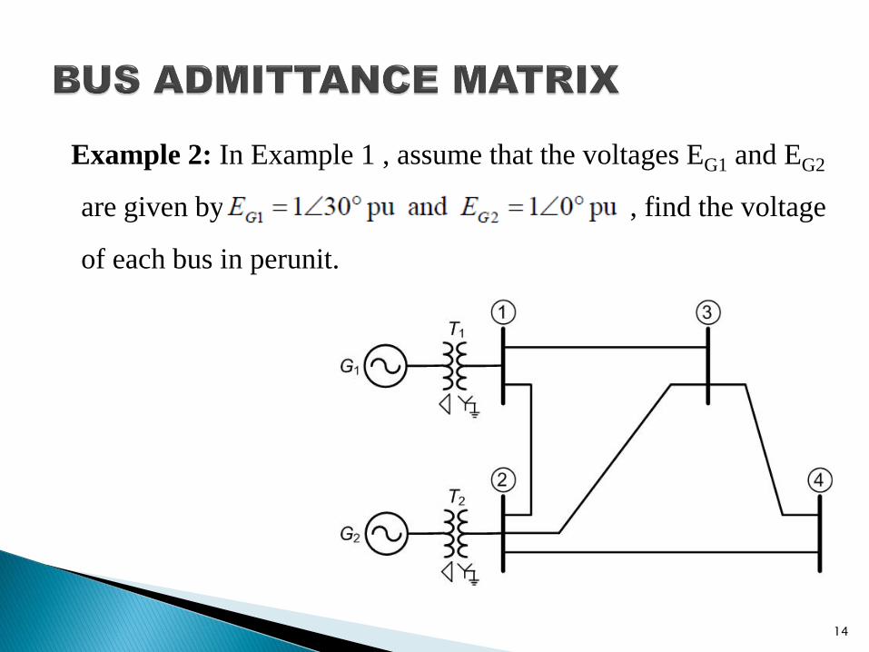
Example 2: In Example 1 , assume that the voltages EG1 and EG2
are given by , find the voltage
of each bus in perunit.
14
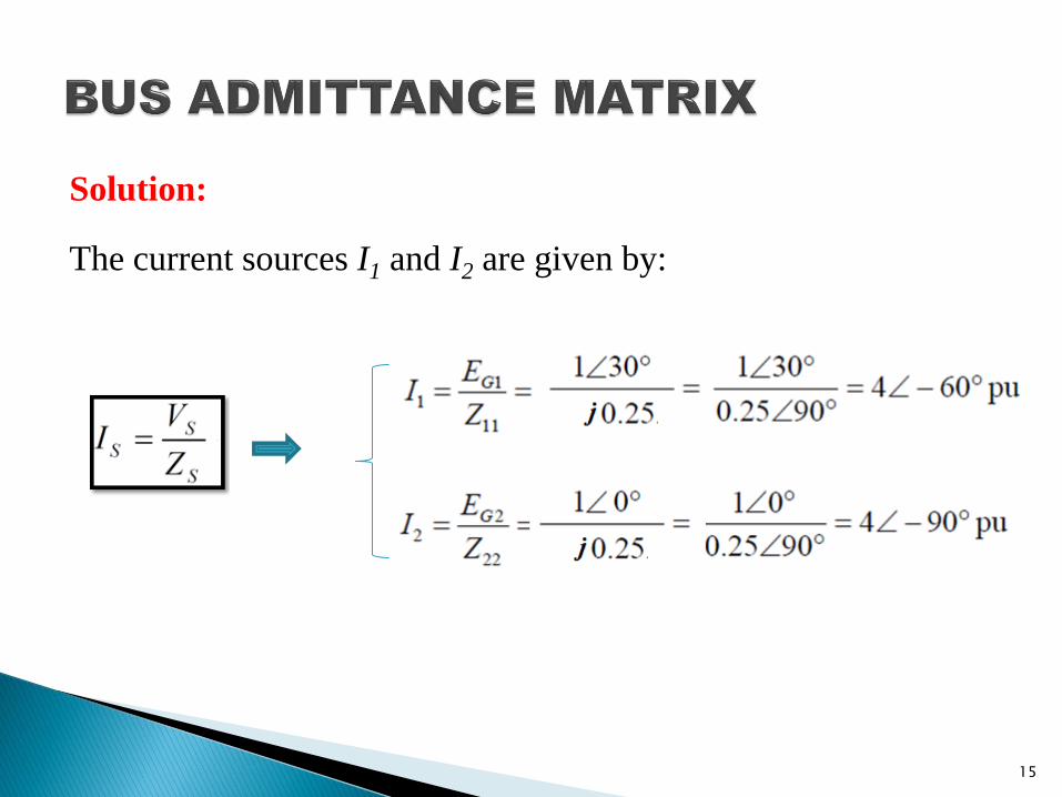
Solution:
The current sources I1 and I2 are given by:
15
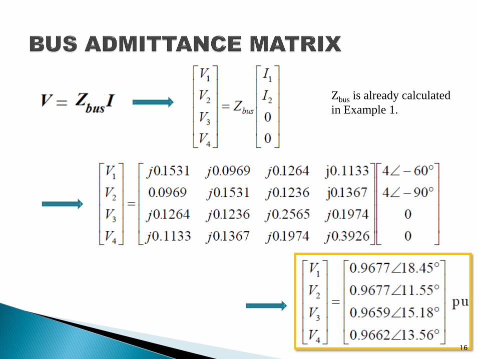
Zbus is already calculated
in Example 1.
16
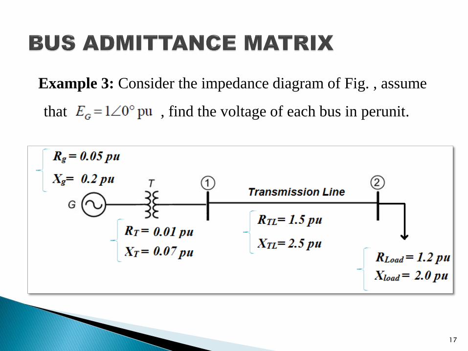
Example 3: Consider the impedance diagram of Fig. , assume
that , find the voltage of each bus in perunit.
17
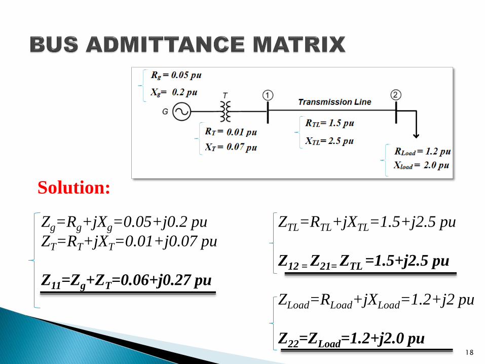
Zg=Rg+jXg=0.05+j0.2 pu
ZT=RT+jXT=0.01+j0.07 pu
Z11=Zg+ZT=0.06+j0.27 pu
ZTL=RTL+jXTL=1.5+j2.5 pu
Z12 = Z21= ZTL =1.5+j2.5 pu
ZLoad=RLoad+jXLoad=1.2+j2 pu
Z22=ZLoad=1.2+j2.0 pu
Solution:
18
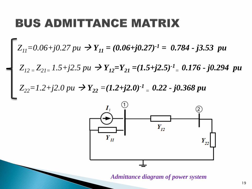
Z11=0.06+j0.27 pu Y11 = (0.06+j0.27)-1 = 0.784 - j3.53 pu
Z12 = Z21= 1.5+j2.5 pu Y12=Y21 =(1.5+j2.5)-1= 0.176 - j0.294 pu
Z22=1.2+j2.0 pu Y22 =(1.2+j2.0)-1 = 0.22 - j0.368 pu
Admittance diagram of power system
1
19
pu
1
20
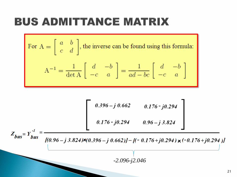
-2.096-j2.046
21
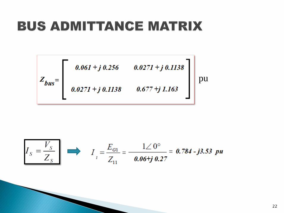
pu
22
1
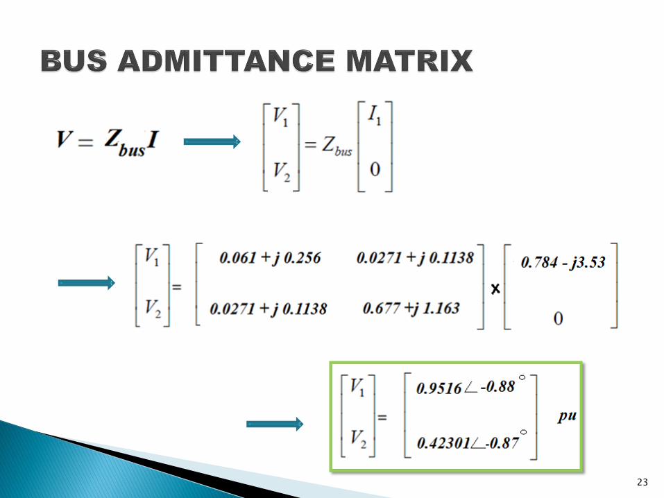
23