Embed Size (px)
Citation preview
the availability of power for the efficient quarrying, finishing
and transport since granite is heavy (170 lbs. per cubic foot)
and very difficult to work. Roughly, from the mid 19th centu-
ry to the mid 20th century, the granite industry progressed
through manual power, draft animal, water wheel, water tur-
bine, steam engine, steam turbine, compressed air engine,
electric motor, and internal combustion engine. It is nothing
less than an historical parade of this nation's principal sources
of power.
The basic problem is the conversion of energy from vari-
ous sources (draft animals, falling water, burning wood or
coal, etc.) into motive power and then transmitting that power
to the granite working and moving machinery. The cost of
power is typically only a small part of the total cost of a gran-
ite operation but it is a critical part – any power interruption
can shut down the entire manufacturing process. Granite
companies need continuous power for continuous operation
and power reserve to meet peak demands. Granite became a
major nation-wide industry only after the introduction of
highly efficient tools and machines and the availability of
reliable power to run them. In the end, the choice of a power
source depended on the scale of the granite operation, the
number and size of local water power sites, the local avail-
ability and cost of fuel, and the possibility of sharing power
sources with other local industries.
Initially, the quarrying, lifting, moving, and finishing of
granite were manual operations. Granite was quarried with
hand tools such as the hand drill, drilling hammer, and wedge
and shims. Granite was lifted and moved by lever, hand-oper-
ated derrick, sledge and rollers. Granite was finished with
hand tools such as the hand hammer and chisel. Manual gran-
ite quarrying and finishing was a slow and costly process and
only relatively small granite pieces could be lifted and moved.
Except for coastal quarries where boat transport was avail-
able, granite markets were limited to areas within a few miles
of the quarry. The granite products were relatively simple –
mostly stones for foundations, hearths, steps, sills, lintels and
posts. Next, draft animals (horses and oxen) were employed
under human guidance to lift, move and transport granite. A
horse could provide a continuous one-half horsepower where-
as a man could produce only about one-eighth continuous
horsepower. The upkeep cost of a horse was about the same
as the salary of a skilled worker. Quarry overburden was
removed by ox shovel and wagon. Lifting of quarry blocks
5
Figure 1. Horse Sweep-Powered Derrick Hoist, Barre, VT.
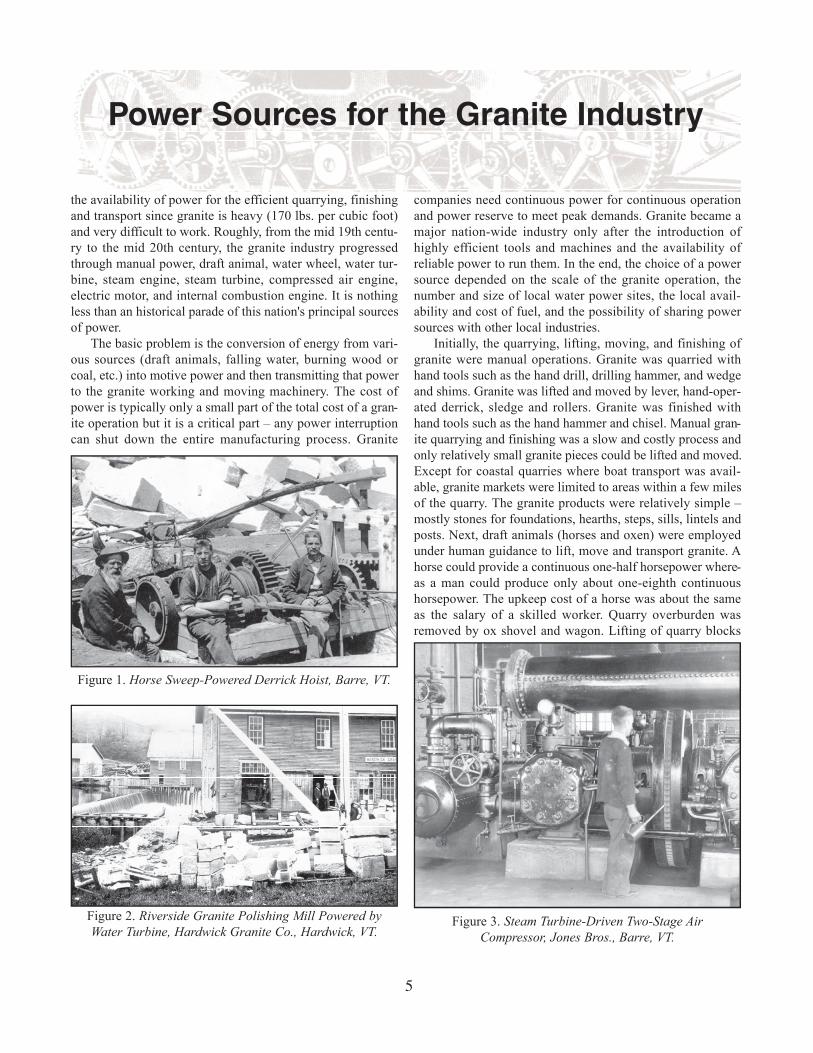
Figure 2. Riverside Granite Polishing Mill Powered by
Water Turbine, Hardwick Granite Co., Hardwick, VT.Figure 3. Steam Turbine-Driven Two-Stage Air
Compressor, Jones Bros., Barre, VT.
Power Sources for the Granite Industry

was done by horse sweep-powered derrick hoists (Fig. 1) and
transport was accomplished by horse and ox-drawn wagon or,
during winter, by sled – sometimes aided by block and tackle
for very steep or muddy roads. Now, granite blocks of many
tons could be lifted and transported.
The granite industry followed the factory system pio-
neered by the textile industry in the early 1800s in Waltham
and Lowell, MA. This included the use of water and later
steam power, the integration of all manufacturing steps in one
building, automated production by complex machinery, and
distribution of power to machines located throughout the
building via millworks. Granite finishing sheds were at first
(prior to the use of steam engines) located at waterpower sites
at a rapids or water falls on streams and rivers for which the
granite company had purchased the water rights or mill priv-
ilege. A millrace (or headrace) was used to channel water
from a dam to a water wheel (overshot, breast or undershot)
which was connected via a millwork (shafts, pulleys and
belts; cranks and rods; cams and lifters; or gears) to the vari-
ous granite-working machines such as gang saws, polishing
machines and lathes. For low water flow and heads of ten feet
or more usually the overshot wheel was used. The breast
wheel could be operated for a range of lower heads but
required a larger water flow. The undershot wheel could be
operated with a small head by utilizing the force of the stream
flow itself but required a large water flow. A water wheel has
the virtue of simplicity – it has only a single moving part, can
be made almost entirely of wood, and can be constructed by
traditional craftsmen such as millwrights, carpenters and
blacksmiths. No precision parts, enclosure or flywheel are
needed. Water wheels rotate slowly – the larger the wheel the
slower the rotation. They mostly range in diameter from eight
to thirty feet with rotation speeds of twenty to five RPM. As
a result, one of the tasks of the millwork was to increase the
rotational speed (by belts, pulleys and gears) to that needed by
the granite-working machines.
Later, by about the 1850s, water wheels were increasing-
ly replaced by water turbines which ran at higher speed and
produced more power (Fig. 2). In addition, turbines were
compact, durable, efficient and low cost. Whereas water
wheels were made primarily of wood, turbines because of
their design complexity and the required strength and close
tolerances were made of iron and were manufactured at dis-
tantly-located factories. The turbine operated with water
under pressure conveyed from a dam via a wooden or iron
penstock. Since turbines were oriented horizontally with ver-
tical shafts, bevel gearing was used to transfer power from the
turbine shaft to the horizontal main shaft of the millworks.
Although water power was relatively inexpensive in opera-
tion (once the costly dam and canal system had been con-
structed), it had two major drawbacks: (1) granite finishing
sheds had to be located next to a waterpower site where there
might not be an available workforce or worker housing and
which exposed the shed to potential flood damage, and (2)
during periods of low rainfall, there might not be enough
water to operate the granite-working machinery.
Millworks typically consisted of a main shaft driven by
the power source and one or more back (or counter) shafts
driven from the main shaft and located over the machines to
be powered. A millworks had three primary functions: (1) dis-
tribution and division of power from the prime mover to mul-
tiple distributed machines, (2) changing rotational speed from
that of the prime mover to that required by each machine, and
(3) changing direction from that of the prime mover (e.g., ver-
tical to horizontal, rotational to reciprocating) to that required
by each machine. Shafting was normally hung from the ceil-
ing so that the moving shafts and belts would be out of the
way of the workers. Power was most often transmitted
between power source, shafting and machines by wooden or
metal pulleys and flat leather belts. By altering the ratio of
pulley diameters on each end of a belt, the rotational speed of
the driven shaft could be increased or decreased. Power could
be applied (or not) to a machine by shifting its belt from an
idler (loose) pulley to a keyed (fixed) pulley (or vice versa),
6
Figure 4. Shay Geared
Locomotive No. 2,
Hardwick & Woodbury
RR, Hardwick, VT.

or by engaging (or disengaging) a belt tightener. For
machines that needed to operate at multiple speeds such as
granite cutting lathes (a slower speed was used for the initial
rough turning), a system of speed reducing gears or a pair of
cone (stepped) pulleys was employed.
By the time inland granite companies began to expand
(1880s and 1890s), steam engines were readily available but
their additional cost of purchase, operation and maintenance
induced many companies to delay their introduction and con-
tinued to depend on water power. With the use of the steam
engine, the drawbacks of water power could be avoided. The
steam engine could be located almost anywhere, could be
designed with a range of output capacities, and was not
dependent on stream flow. However, compared to the water
wheel, the steam engine cost more, had to be shipped at added
cost from a distant manufacturer, had to be continuously
attended and maintained, and was more costly to repair. In
addition, there was increased insurance cost due to the risk of
boiler explosions and fire. These negatives, added to the fact
that small steam engines were not fuel-efficient, meant that
steam engines were mostly installed by large granite firms. In
1909, Jones Brothers, one of the largest granite firms in
Barre,VT, was powered by both water power and by a 150 HP
Corliss steam engine. By 1913, Jones Bros. had a total capac-
ity of 300 HP of mechanical power from both water and
steam. Later, the Jones Bros. wheelhouse contained two cast
iron horizontal wheel water turbines – each with a ten-foot
vertical shaft connected by bevel gears to an electric genera-
tor. There was a clutch for each turbine that connected the tur-
bine to the generator. Either one or both turbines could be
connected, depending on the power requirements and avail-
able water. By the 1930s, the machinery at Jones Bros. was
powered by electricity from the local electric utility (Green
Mountain Power Co.). Two coal-burning Babcock & Wilcox
steam boilers were used for heating only.
Often, the steam engine was just substituted for the water
wheel or water turbine, retaining some or all of the overhead
shafting and pulleys, belts, and gears. Or, the water wheel or
turbine might be retained to provide low-cost power and the
steam engine used as backup or to meet peak loads. Initially,
wood-burning steam boilers were used, supplied with fuel
from local woodlots. As coal became available and as local
wood became scarce and more expensive (ca. 1880s), boilers
were converted to burn coal. Also, coal allowed the use of
mechanical stokers to replace the hand shoveling of coal into
the boilers. For large installations, a coal trestle might be con-
structed for efficient railroad delivery of coal. An important
byproduct of the boiler was the use of steam to heat the sheds
during winter operations. Often, the exhaust steam from a
steam engine or steam turbine was run through pipes in a heat
exchanger. A fan blew air over the hot pipes and into large
diameter ducts for distribution of hot air throughout the gran-
ite shed.
Just as water wheels were replaced by water turbines,
reciprocating piston steam engines were replaced by steam
turbines where greater power and rotational speed were need-
ed such as for air compressors and electric generators (Fig. 3).
Turbines are best used for applications requiring high rota-
tional speed and continuous operation. Compared to the
steam engine, the steam turbine is simpler, having only one
moving part. In addition, the steam turbine has lower size and
lower weight per horse power, higher efficiency (for large
sizes), and can run for months unattended.
7
Figure 5. Steam Piston-Powered Derrick Hoist,
Barre, VT.
Figure 6. Electric Motor Drive for Air Compressor. (The
small motor is a starter motor.) Jones Bros., Barre, VT.

The mobility of the steam engine made possible the low-
cost transport of granite via railroad and opened up the interi-
or granite quarries for exploitation. Before this time only the
coastal quarries, serviced by sloops and schooners, could be
profitably operated. Overland transport by horses and oxen
was both slow and expensive. Really heavy loads (50 tons)
might require a team of two or three dozen oxen and horses
and might proceed at the snail-like pace of one or two miles
per week! In addition, the heavy granite loads caused deep
ruts in the dirt roads and crushed the culverts running under
them, much to the anger of local residents. Initially, locomo-
tives were wood fired but by the 1880s were being rapidly
converted to coal. Coal weighed half or less and had a volume
several times less than seasoned hardwood of the same heat-
ing value. By carrying their own fuel, wood or coal in tenders,
locomotives were not tethered to a stationary power source.
Although by the 1870s interior New England was well serv-
iced by rail, it was not until quarry railroads, with their steep
grades and sharp curves, were built in the 1880s and 1890s to
haul granite from the quarries to the finishing sheds that the
interior New England granite companies really began to pros-
per. Strong-traction saddletank locomotives were often used
on quarry railroads and, for extreme grades, geared locomo-
tives on which all the wheels were driven were used to pro-
vide outstanding tractive power for grades of 10% and more
(Fig. 4).
Quarries posed special problems with respect to power.
Quarries were often located at higher elevations with no
rivers or streams for water power. By the 1870s and 1880s,
coal was often transported to the quarry by wagon to fire boil-
ers which provided steam for drills and derrick hoists (Fig. 5).
Later, if the quarry was serviced by a railroad, coal might be
brought in very economically. Sometimes water was so scarce
that it was a challenge even to find enough to replace the
steam engine’s escaped steam and for wet drilling (the use of
water to remove granite cuttings from the drill hole and to
keep down the dust). Although the high and exposed location
of many quarries suggests the possibility of using wind
power, the author is not aware of this source having been used
in the granite industry. The only significant New England use
of wind power appears to have been on waterpower-poor
Cape Cod for the salt industry and for grist milling. In any
case, even the largest windmills of that time produced only
three to five horsepower, far less than the power needed for
the typical granite operation.
As mentioned above, steam was initially (ca. 1870s and
1880s) used to power quarry drills and derrick hoists. Steam
was difficult to handle and always dangerous. After the
1880s, compressed air gradually replaced steam. Pneumatic
rock drilling was pioneered in the U.S. in 1866 at the Hoosac
Tunnel in western MA, powered by air compressors directly
connected to water turbines. When compressed air began to
be used in the granite industry in the late 1800s, first steam
turbines and then electric motors were used to drive air com-
pressors. Compressed air has many advantages: there is an
inexhaustible supply of air and air exhaust is no problem, pipe
leaks are not as dangerous, compressed air can be transmitted
several miles without significant loss, it can be easily subdi-
vided for use by many tools and machines, and can be used
expansively in unmodified steam engines or in a variety of
specialized air motors. The one major drawback was air com-
pressor inefficiency (only 40-55% in the 1890s) due to heat
loss during compression. However, the convenience of com-
pressed air more than compensated for this inefficiency. Air
compressors require relatively high torque and rotational
speed which could be delivered by steam turbines. Electric
motors did an even better job of driving air compressors (Fig.
6). The use of compressed air deep hole quarry drills, plug
drills, jackhammers, and derrick hoists as well as surfacing
machines (to produce flat granite surfaces) and hand-held
pneumatic carving tools in the finishing sheds did not really
become widespread until the advent of the electric motor-
driven air compressor in the 1890s.
The next major step in power technology was the intro-
duction of electrical power in the 1890s. Initially granite
sheds produced their own electric power by water or steam
turbine-powered generators. In 1909, The Woodbury Granite
Co. of Hardwick,VT, the largest building (construction) gran-
ite company in the U.S., had their own proprietary electric
power plant with two hydrogenerators producing a total of
500 KW (373 HP). By 1913, the Woodbury Granite Co.
power plant could generate 1000 HP of hydro power and 2000
HP of backup steam power. The Woodbury Granite Co. fired
the steam boilers with sawdust and waste slabs from it’s
sawmill whenever possible and only burned the more expen-
sive coal when the scrap wood was not available (Fig. 7).
Later, in the early 20th century, public electric power utilities
increasingly supplied power to the sheds. At first, a single
large electric motor would be used to replace the steam engine
or turbine, using existing millworks. As smaller, lower-cost
motors became available, multiple motors were used, each
powering a group of similar co-located granite-working
8
Figure 7. Babcock & Wilcox 1000 HP Vertical Steam
Boiler, Woodbury Granite Co., Hardwick, VT.

machines. Finally, each machine was manufactured with its
own integral electric motor. The use of one motor per
machine greatly simplified power transmission from motor to
machine (usually a geared or direct connection) and meant
that the motor needed to be running only when the machine
was in operation. Also, a machine with an integral motor
could be more easily moved. Finally, and perhaps most
important, the mechanical millworks which consumed from
20% to 50% of the power generated were replaced by electri-
cal connections that consumed 5% or less of the power gen-
erated. As electric motors continued to decrease in size, the
power per motor volume and weight increased and hand-held
tools were developed with integral motors powered via an
electric cord. (An early pre-electric example of a machine
with a “built-in” motor was the tub wheel grist mill in which
a horizontal water wheel with vertical shaft was directly con-
nected to the upper mill stone.)
An important byproduct of the electric generator was the
ability to use electric lighting. Centrally-generated electricity
was originally introduced as power for the electric light with
power for the electric motor as a byproduct. Much granite
working required good light, for example for fine carving and
sculpting, and electric light bulbs were able to provide
improved lighting during late winter afternoons and cloudy
days. A typical installation was a row of 500 watt light bulbs
with porcelain reflectors hung below the shed roof ridgeline
at intervals of twelve feet or so.
Since the cost per horsepower decreases as the prime
mover size and capacity increases, economy of scale drove
the granite industry to build boiler houses with multiple large
steam boilers (usually, due to fire hazard, a masonry building
separate from the main shed), to build compressor rooms with
multiple large air compressors, and finally to purchase elec-
tric power from public utilities. This both reduced the cost of
power and improved reliability by the backup power genera-
tion capability of multiple prime movers. Often an entrepre-
neur would install a large air compressor and sell compressed
air to surrounding small to medium-sized granite sheds that
couldn’t afford to buy a compressor. Or, an entrepreneur
might build a granite shed
with compressed air, electrici-
ty, heat and lighting and rent
space to small granite firms.
Sometimes, a small firm pur-
chased surplus compressed air
or electric power from a large
neighboring firm.
At high voltages, electri-
cal power can be transmitted
over long distances without
significant energy loss which
makes region-wide electric
utilities possible and allows
the tapping of previously
unexploited remote water-
power sites by hydroelectric
power. Steam and compressed air is more difficult to trans-
port over long distances due to frictional and heat losses and
therefore led to the use of localized boiler houses and com-
pressor rooms. Transport of power mechanically, for example
by hemp or manila rope, or by steel cable or rods, is even
more limited, typically a mile or less. Steam and compressed
air was transported to work sites or stations by large diameter
(four inches) rigid threaded iron pipes. At each work site or
station, a smaller diameter (one half to one and a half inches)
flexible rubber hose tapped off the iron pipe (through a turn-
off valve) to power a tool or machine. For compressed air sys-
tems, a small diameter (three-quarter inch) steam pipe was
often run inside the larger diameter iron pipe to heat the air
and decrease the relative humidity. If not heated, the temper-
ature of the exhaust air from the tool would be so low that the
tool’s valves and ports would freeze up, especially during
winter, disabling the tool.
Mention has been made above of moving and lifting gran-
ite in the quarry. Material handling in the finishing shed was
an even more challenging problem – granite had to be moved
expeditiously from one workstation to the next for the various
finishing steps. The solution to this problem was the overhead
traveling bridge crane which could reach any part of a rectan-
gular-shaped building, called a “straight shed”. A typical shed
of a medium to large-size company was several hundred feet
long and had one or two overhead cranes that were in constant
motion supplying the needs of one to two hundred granite
workers. The key difficulty was how to power a machine that
was moving over an area forty feet wide and several hundred
feet long. The first solution was the “flying rope” overhead
crane which was powered by an endless loop of rope, driven
by a steam engine or electric motor, which ran the length of
the shed on pulleys (Fig. 8). The rope loop ran onto the crane
which moved on tracks over the length of the shed. The rope
powered the movement of the bridge over the length of the
shed, the movement of the trolley over the length of the
bridge, and the movement of the hoist drum that was located
on the trolley. There were two difficulties with this design: (1)
the mechanism to translate the power of the moving rope to
9
Figure 8. Rope-Driven Overhead Traveling Bridge Crane, Manufactured by
Lane Mfg. Co., Montpelier, VT

the motion of the bridge, trolley and hoist was complex and
required frequent costly repairs and (2) the long loop of 1 to
1_-inch diameter rope moving at high speeds was dangerous
– inone case having come off its pulleys and decapitated a
worker. (Another example of a rope-powered machine for
moving granite, in this case using wire rope, was the cable-
way or Blondin used in the quarries to move waste granite
and small granite blocks.) The best solution to powering the
overhead traveling crane came with the availability of the
smaller lower-cost electric motor. Three motors were used,
one on the bridge to power bridge movement and two on the
trolley to power trolley and hoist movement. Electric power
was conveyed to the motors via conducting wheels that ran on
bare copper wires strung the length of the shed and the length
of the crane bridge.
Later in the 20th century, the internal combustion engine
(diesel) began to power both electric generators and air com-
pressors, especially at the quarry where, due to its remoteness,
central electric service was often not readily available. In
modern quarries, the diesel engine also powers large forklift
trucks and long-haul flatbed trucks. The Fletcher Quarry in
Woodbury, Vermont’s highest producing quarry, consumes
40,000 gallons of diesel fuel per year. Although a small gas
engine with gas tank can be designed integral with a tool (like
a chain saw or lawn string trimmer), the author is not aware
of any such tools for the granite industry – probably since gas
engine-powered electric generators or air compressors can
readily provide electricity or compressed air for electric or
pneumatic tools at the working site. Since most granite-work-
ing tools require lots of power, a self-contained fuel supply is
not really a good option and the tools must therefore be teth-
ered to their power source to insure an adequate flow of
power to the tool.
For the purposes of this article, a tool is defined as a hand-
held and hand-guided unit designed to carry out a particular
granite-working task. A tool may be human-powered or may
be powered by steam, compressed air, or electricity via a
steam hose, compressed air hose, or electric cable with,
respectively, an integral steam engine (usually a small piston
steam engine), compressed air engine (usually a small piston
air engine) or electric motor. Although power can be supplied
to hand-held tools via flexible shafting or belt arrangements,
steam, compressed air and electric power connections are
more flexible and allow the operator to more easily hold,
move and guide the tool to perform its intended work. In fact,
one of the key problems of tool design for granite working is
the application of non-human power under the fine motor
control of a human operator. Electrical connections are prob-
ably the most desirable, being flexible and lightweight, hav-
ing low power transmission loss, and being simple to connect,
for example by a plug. Steam and air hoses must be heavy and
strong enough to withstand high pressure, heat, and moisture.
A machine is defined as a non-hand-held unit designed to
carry out a particular granite-working task. A machine may be
human powered but is normally powered through mechanical
power transmission from an animal, water wheel/turbine or
steam engine, or (as with a tool) by an integral engine/motor
powered by steam, compressed air or electricity. A machine
may be fixed (for example, bolted down), moveable (for
example, on tracks), or portable (for example, on wheels). A
stone may either be brought to the machine (for example, a
gang saw, a very large twelve-foot by forty-foot machine
which is bolted down) or the machine may be brought to the
stone (for example, a pneumatic surfacer, a much smaller
machine typically mounted on wheels). For most granite-
working machines, the stone remains static while the
machine’s working head moves. One exception is the lathe
where both the stone and the working head (cutting disc)
move. A machine may require continuous human guidance
(for example, a polisher in which the polishing wheel is con-
tinuously moved by hand over the granite surface), may be
semi-automatic requiring periodic adjustments (for example,
a quarry drill for which ever longer drill bits have to be
employed as the drill hole deepens), or may be fully-automat-
ic where instructions are issued via mechanical adjustments
or settings, buttons, switches or keyboard after which the
machine can complete a job unattended (for example, a gang
saw for which the stone is positioned, the number and spac-
ing of the saw blades set, and then the saw left to run with an
abrasive slurry continuously delivered by a pump until the
saw block is sawn through).
Since granite-working tools and machines work on gran-
ite mechanically (drill, split, break, saw, trim, hammer, carve,
polish, grind, turn, sand blast, and crush), power has to be
eventually translated into mechanical motion – driving steel
or abrasives against the granite. (An exception is the flame
channeler in which a high-temperature oil-oxygen flame
spalls off chips by causing rapid temperature changes in the
granite. The flame channeler is a complex machine, requiring
inputs of oil, oxygen, water, electricity, and compressed air.)
A water wheel or a water or steam turbine drives a shaft in a
rotary motion which can be converted, if necessary, to a lin-
ear motion (for example, for a gang saw) by placing a crank
on the shaft which drives the machine via a pitman rod. A
steam, compressed air or gasoline-driven piston moves in a
linear trajectory which can be converted, if necessary, to a
rotary motion (for example, for a derrick hoist drum) by caus-
ing the piston rod to drive the machine via a shaft with a
crank. If power is transmitted by compressed air or electrici-
ty, two additional steps are required between the prime mover
and the final mechanical motion for granite working – power
converter and secondary mover. For compressed air transmis-
sion, mechanical power needs to be converted to compressed
air power by an air compressor and then converted back to
mechanical power by an air motor. For electrical transmis-
sion, mechanical power needs to be converted to electrical
power by an electric generator and then converted back to
mechanical power by an electric motor.
Table 1 summarizes the power sources, prime movers,
power converters, power transmission, and secondary movers
10

for tools and machinery used in the granite industry. The
power sources are shown in rough time order (from top to
bottom) of utilization. The transmission of power is in four
forms: mechanical (M), steam (S), compressed air (A), and
electricity (E). Certain forms of power such a windmill prime
movers, power transmission by hydraulic pressure, and tools
with integral internal combustion engines have not been
included since they were not commonly used in the granite
industry.
Table 1 lists examples of tools and machines of the gran-
ite industry and shows how they fit into Table 1. Power
Source 1 is man. Power Source 2 is draft animals. Power
Source 3 is water wheel/turbine, steam engine/turbine or elec-
tric motor external to and mechanically coupled to the tool or
machine. Power Source 4 is steam, compressed air or electric-
ity used to power a steam engine/turbine, compressed air
engine/turbine or electric motor integral with the tool or
machine. Those tools or
machines with Power Sources
3 or 4 but not Power Source 1
are automatic or semi-automat-
ic – that is, do not require the
continuous guidance and con-
trol of a human operator. The
very important derrick hoist,
used for heavy lifting both at
the quarry and in the shed yard,
is unusual among machines
used in the granite industry
since over time, it has been
powered manually, by draft
animals, by steam, by com-
pressed air, and finally by elec-
tricity. Channeling, the cutting
of a deep groove or channel
around a block to be removed
from the quarry, is a process
that also has evolved through a
number of technologies: steam
quarry drill with broaching bit,
channeling machine with an
array of steam-powered chis-
els, pneumatic quarry drill with
broaching bit, wire saw, pneu-
matic core drill, high-tempera-
ture flame channeler, and high-
pressure water channeler.
One machine that is not
represented by Table 1 is the
early steam-driven, track-
mounted channeling machine
with an integral steam boiler
that powered an array of chis-
els. This large and cumber-
some machine was rapidly sup-
planted by a machine with an external boiler and a steam hose
connection. I am not aware of any granite-working tools or
machines with integral water turbine and pressure water hose
connection or with an integral gas engine and integral gas
tank or gas hose connection. There may have been experi-
mental or small production examples of these but if so they
never gained popularity in the granite industry. The high pres-
sure water channeler and Hydrosplitter have integral electric
motor driven water and oil pumps, respectively. In the former,
the stream of high pressure water acts as an abrasive to wear
away the granite. In the latter, hydraulic cylinders drive a
knife at high pressure against a granite block, splitting the
block along the knife edge.Paul Wood
Wellesley Hills, MA
11
Table 1. Power Sources for Selected Tools and Machines
Tool (T) or Machine (M) Power Source
1 2 3 4
Drilling Hammer (T) X
Hand Drill (T) X
Wedge & Shims (T) X
Striking Hammer (T) X
Bull Set (T) X
Hand Hammer (T) X
Hand Chisel (T) X
Stone Jack (M) X
Polishing Machine (Manual) (M) X
Derrick Hoist (Manual) (M) X
Ox Shovel/Scraper (M) X X
Wagon (M) X X
Sled (M) X X
Derrick Hoist (Draft Animal) (M) X X
Polishing Machine (M) X X
Gang Saw (M) X
Lathe (M) X
Overhead Crane (Rope) (M) X X
Wire Saw (M) X
Contour Wire Saw (M) X X
Surfacing Machine (Mechanical) (M) X X
Grinder (M) X
Sand Blast Machine (M) X A and E
Plug Drill (T) X A
Quarry Drill (M) S or A
Derrick Hoist (M) X S, A or E
Pneumatic Carving Tool (T) X A
Surfacing Machine (Pneumatic) (M) X A
Overhead Crane (Electric) (M) X E
Polisher (Hand-held) (T) X E
Water Pump (M) S
Grinder (Hand-held) (T) X E
Engraving Tool (T) X E
Water Channeler (M) E
Hydrosplitter (M) E
Flame Channeler (M) X A and E


![[SIA] - goteborg.se](https://img.pdfslide.us/doc/110x75/61921deaf8610c3b19195631/sia-.jpg)