Embed Size (px)
Citation preview
Asian Journal of Electrical Sciences ISSN: 2249- 6297, Vol. 5 No. 2, 2016, pp. 5-17
© The Research Publication, www.trp.org.in
Power Quality Disturbance Mitigation Using Filters Incorporating Neural Network Controller
R. Shilpa1 and P.S Puttaswamy2
1 Research Scholar, 2Professor Department of Electrical & Electronics Engineering
P E S College of Engineering, Mandya, India
Email: [email protected], [email protected] Abstract - Now a Days Harmonics in power systems is becoming a crucial issue due to the abrupt rise in the use of nonlinear loads. A Power Filter is one of the best answers to this problem.The filter performs the job by injecting compensatory currents that counteract them at the Point where seclusion has to be provided from non linearities. In order to infuse these compensatory currents unerringly,through the inverter which requires proper gating signals that trail the reference currents precisely through a controller. The reference current provides an estimation of the amount of harmonics. Consequently, perfect calculation of these reference signals foster generation of proper gating signals for the inverter are required.Accurate estimation is done using the P-Q theory, D-Q theory as well as the Adaline for Shunt and Hybrid Power Filter. DC Voltage across the capacitor is regulated using the PI controller and the Neural Network based control. Keywords : Power Quality, Total Harmonic Distortion, Hybrid Filters, Neural Network Controller, Hysterisis Controller.
I.INTRODUCTION The Quality of Power has been an important factor for long. From laymen to Power Engineers electronic goods to mechanical devices, and domestic appliances to industrial ones all are immediately or indirectly exerting influence on the grade and the supremacy of the power saved. It is comprehensive to spell out this quality of the power collectively as the quality of the voltage and the quality of current togetherness. A variation or rather deterioration of this power will definitely knock out proper operation of equipments and could also produce damage and havoc be it in modest scale or on a big scale. It can spring up at transmission, distribution or by the consumers of power. With the copious number of electronic equipments flooding the market and their use is increased , The pollution in the electric lines induced by the consumers is on the rise too. Enough attention needs to be provided in this area, though conditioning systems of power lines are in place, FACTS based devices, etc. are prevalent at the transmission and distribution sides. Hence the phrase Power Quality is deeply important today and its mitigation techniques have become profuse since late 1980s.Harmonics encompasses a wider span of the problems caused by lower grade and lesser distinction of the power. In simple terms harmonics can be defined as wholesome multiples of the fundamental voltage or
current frequencies at which a system operates. In the power domain the fundamental frequency used could be 50 Hz. The Second harmonic refers to twice the fundamental while a third refers to thrice the fundamental voltage or current frequencies, similarly a fourth, fifth and so on. Often many orders of harmonics are observed to be present together in the system rather than a single harmonic being present. The main reason for the harmonics stems from the increased use of nonlinear loads and fast switching. With increasing number of nonlinear loads being used today, the problems caused by harmonics have been aggravated. In fact Harmonics cause myriad problems. Hence, analysis of the harmonics in fact gives us a revelation about the current drawn by these non linear loads which use transformer less power supplies in most of the equipments like computers, the Light emitting diodes, variable speed drives, refrigerators, etc. Taking into consideration certain loads like medical devices, a malfunction of the devices or other loads cannot be thought of. In both industrial applications and domestic side, it could lead to inconvenient tripping and these can also lead to long enduring blackouts. In cases like data transmission, it can also lead to muddled data which is nothing but data being corrupted during display, or during encoding wherein it becomes an erroneous or faulty transmission. Hereby harmonics intrudes or trespasses into the communication systems too. Harmonics could cause fake tripping of circuit breakers and mal operation of the fuse. Power converters like AC to DC converters are also at stake due to harmonics. As the order of harmonics in a system increases the menace it creates also amplifies. Thus the increased use of power electronic devices in turn leads to harmonics in the system. Also the large amount of harmonics can result in malfunctioning of the systems, leading to downtime and increased operating costs. The Principle of injection of harmonics into the line currents by the nonlinear loads is shown in Figure 1. The Load current essentially split as fundamental current and the harmonic components. Though it's a far-fetched dream to achieve absolutely pure sinusoidal currents and voltages, it can be strived to reduce the amount of harmonics and bring in the desired level of accuracy for achieving faultless flow of current. A standard measure of this is the THD abbreviated precisely as Total Harmonic Distortion.
5 AJES Vol.5 No.2 July-December 2016
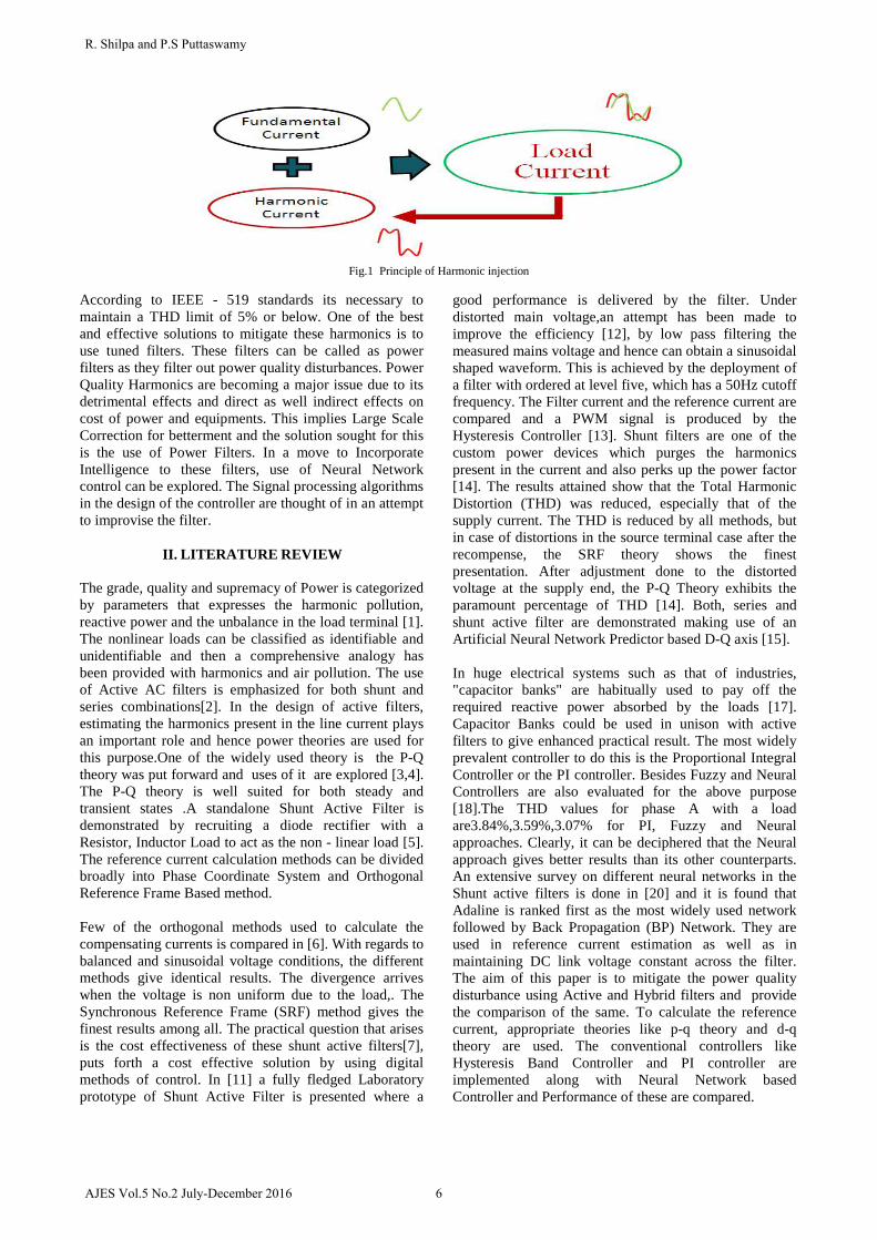
Fig.1 Principle of Harmonic injection According to IEEE - 519 standards its necessary to maintain a THD limit of 5% or below. One of the best and effective solutions to mitigate these harmonics is to use tuned filters. These filters can be called as power filters as they filter out power quality disturbances. Power Quality Harmonics are becoming a major issue due to its detrimental effects and direct as well indirect effects on cost of power and equipments. This implies Large Scale Correction for betterment and the solution sought for this is the use of Power Filters. In a move to Incorporate Intelligence to these filters, use of Neural Network control can be explored. The Signal processing algorithms in the design of the controller are thought of in an attempt to improvise the filter.
II. LITERATURE REVIEW The grade, quality and supremacy of Power is categorized by parameters that expresses the harmonic pollution, reactive power and the unbalance in the load terminal [1]. The nonlinear loads can be classified as identifiable and unidentifiable and then a comprehensive analogy has been provided with harmonics and air pollution. The use of Active AC filters is emphasized for both shunt and series combinations[2]. In the design of active filters, estimating the harmonics present in the line current plays an important role and hence power theories are used for this purpose.One of the widely used theory is the P-Q theory was put forward and uses of it are explored [3,4]. The P-Q theory is well suited for both steady and transient states .A standalone Shunt Active Filter is demonstrated by recruiting a diode rectifier with a Resistor, Inductor Load to act as the non - linear load [5]. The reference current calculation methods can be divided broadly into Phase Coordinate System and Orthogonal Reference Frame Based method. Few of the orthogonal methods used to calculate the compensating currents is compared in [6]. With regards to balanced and sinusoidal voltage conditions, the different methods give identical results. The divergence arrives when the voltage is non uniform due to the load,. The Synchronous Reference Frame (SRF) method gives the finest results among all. The practical question that arises is the cost effectiveness of these shunt active filters[7], puts forth a cost effective solution by using digital methods of control. In [11] a fully fledged Laboratory prototype of Shunt Active Filter is presented where a
good performance is delivered by the filter. Under distorted main voltage,an attempt has been made to improve the efficiency [12], by low pass filtering the measured mains voltage and hence can obtain a sinusoidal shaped waveform. This is achieved by the deployment of a filter with ordered at level five, which has a 50Hz cutoff frequency. The Filter current and the reference current are compared and a PWM signal is produced by the Hysteresis Controller [13]. Shunt filters are one of the custom power devices which purges the harmonics present in the current and also perks up the power factor [14]. The results attained show that the Total Harmonic Distortion (THD) was reduced, especially that of the supply current. The THD is reduced by all methods, but in case of distortions in the source terminal case after the recompense, the SRF theory shows the finest presentation. After adjustment done to the distorted voltage at the supply end, the P-Q Theory exhibits the paramount percentage of THD [14]. Both, series and shunt active filter are demonstrated making use of an Artificial Neural Network Predictor based D-Q axis [15]. In huge electrical systems such as that of industries, "capacitor banks" are habitually used to pay off the required reactive power absorbed by the loads [17]. Capacitor Banks could be used in unison with active filters to give enhanced practical result. The most widely prevalent controller to do this is the Proportional Integral Controller or the PI controller. Besides Fuzzy and Neural Controllers are also evaluated for the above purpose [18].The THD values for phase A with a load are3.84%,3.59%,3.07% for PI, Fuzzy and Neural approaches. Clearly, it can be deciphered that the Neural approach gives better results than its other counterparts. An extensive survey on different neural networks in the Shunt active filters is done in [20] and it is found that Adaline is ranked first as the most widely used network followed by Back Propagation (BP) Network. They are used in reference current estimation as well as in maintaining DC link voltage constant across the filter. The aim of this paper is to mitigate the power quality disturbance using Active and Hybrid filters and provide the comparison of the same. To calculate the reference current, appropriate theories like p-q theory and d-q theory are used. The conventional controllers like Hysteresis Band Controller and PI controller are implemented along with Neural Network based Controller and Performance of these are compared.
6AJES Vol.5 No.2 July-December 2016
R. Shilpa and P.S Puttaswamy
III. METHODOLOGY
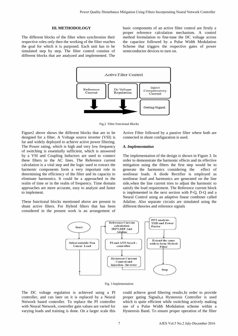
The different blocks of the filter when synchronize their respective roles only then the working of the filter reaches the goal for which it is purposed. Each unit has to be simulated step by step. The filter control consists of different blocks that are analyzed and implemented. The
basic components of an active filter control are firstly a proper reference calculation mechanism. A control method formulation to fine-tune the DC voltage across the capacitor followed by a Pulse Width Modulation Scheme that triggers the respective gates of power semiconductor devices to turn on.
Fig.2 Filter Functional Blocks
Figure2 above shows the different blocks that are to be designed for a filter. A Voltage source inverter (VSI) is far and widely deployed to achieve active power filtering. The Power rating, which is high and very low frequency of switching is essentially sufficient, which is answered by a VSI and Coupling Inductors are used to connect these filters to the AC lines. The Reference current calculation is a vital step and the logic used to extract the harmonic components form a very important role in determining the efficiency of the filter and its capacity to eliminate harmonics. It could be a approached in the realm of time or in the realm of frequency. Time domain approaches are more accurate, easy to analyze and faster to implement. These functional blocks mentioned above are present in shunt active filters. For Hybrid filters that has been considered in the present work is an arrangement of
Active Filter followed by a passive filter where both are connected in shunt configuration is used. A. Implementation
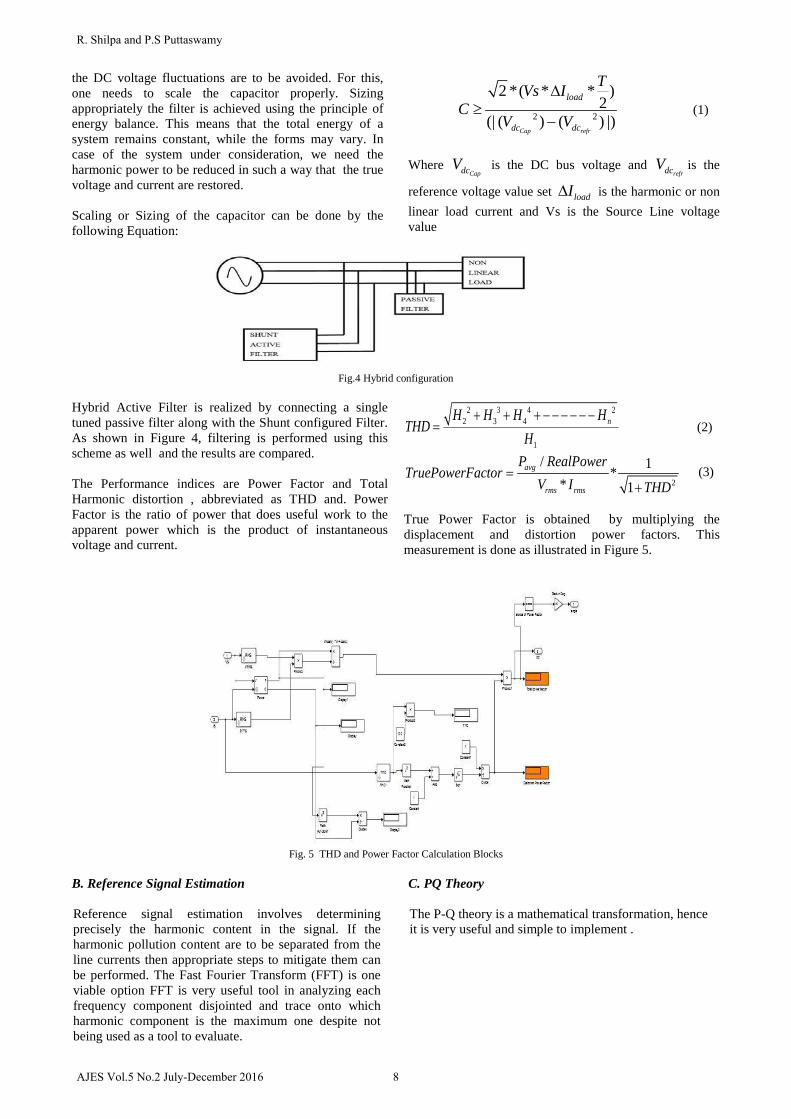
The implementation of the design is shown in Figure 3. In order to demonstrate the harmonic effects and its effective mitigation using the filters the first step would be to generate the harmonics considering the effect of nonlinear loads. A diode Rectifier is employed as nonlinear load and harmonics are generated on the line side,when the line current tries to adjust the harmonic to satisfy the load requirement. The Reference current block is implemented in the next section with P-Q, D-Q and a Neural Control using an adaptive linear combiner called Adaline. Also separate circuits are simulated using the different theories and reference signals
Fig. 3 Implementation
The DC voltage regulation is achieved using a PI controller, and can later on it is replaced by a Neural Network based controller. To replace the PI controller with Neural Network, controller gain values are varied for varying loads and training is done. On a larger scale this
could achieve good filtering results.In order to provide proper gating Signals,a Hysteresis Controller is used which is quite efficient while switching actively making use of a Pulse Width Modulation scheme within a Hysteresis Band. To ensure proper operation of the filter
7 AJES Vol.5 No.2 July-December 2016
Power Quality Disturbance Mitigation Using Filters Incorporating Neural Network Controller
the DC voltage fluctuations are to be avoided. For this, one needs to scale the capacitor properly. Sizing appropriately the filter is achieved using the principle of energy balance. This means that the total energy of a system remains constant, while the forms may vary. In case of the system under consideration, we need the harmonic power to be reduced in such a way that the true voltage and current are restored. Scaling or Sizing of the capacitor can be done by the following Equation:
2 2
2 *( * * )2
(| ( ) ( ) |)Cap refr
load
dc dc
TVs IC
V V
∆≥
− (1)
Where
CapdcV is the DC bus voltage and refrdcV is the
reference voltage value set loadI∆ is the harmonic or non linear load current and Vs is the Source Line voltage value
Fig.4 Hybrid configuration
Hybrid Active Filter is realized by connecting a single tuned passive filter along with the Shunt configured Filter. As shown in Figure 4, filtering is performed using this scheme as well and the results are compared. The Performance indices are Power Factor and Total Harmonic distortion , abbreviated as THD and. Power Factor is the ratio of power that does useful work to the apparent power which is the product of instantaneous voltage and current.
2 3 4 22 3 4
1
nH H H HTHD
H+ + + − − − − − −
= (2)
2
/ 1** 1
avg
rms rms
P RealPowerTruePowerFactor
V I THD=
+ (3)
True Power Factor is obtained by multiplying the displacement and distortion power factors. This measurement is done as illustrated in Figure 5.
Fig. 5 THD and Power Factor Calculation Blocks B. Reference Signal Estimation Reference signal estimation involves determining precisely the harmonic content in the signal. If the harmonic pollution content are to be separated from the line currents then appropriate steps to mitigate them can be performed. The Fast Fourier Transform (FFT) is one viable option FFT is very useful tool in analyzing each frequency component disjointed and trace onto which harmonic component is the maximum one despite not being used as a tool to evaluate.
C. PQ Theory The P-Q theory is a mathematical transformation, hence it is very useful and simple to implement .
8AJES Vol.5 No.2 July-December 2016
R. Shilpa and P.S Puttaswamy
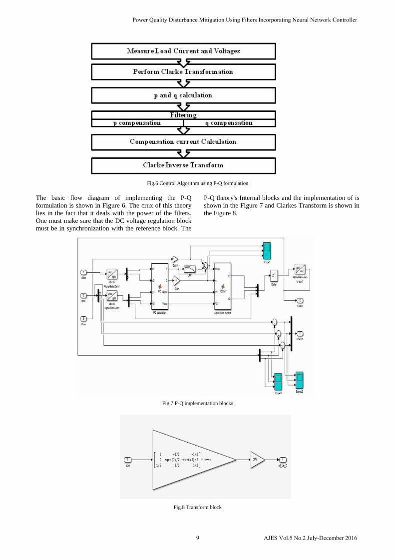
Fig.6 Control Algorithm using P-Q formulation The basic flow diagram of implementing the P-Q formulation is shown in Figure 6. The crux of this theory lies in the fact that it deals with the power of the filters. One must make sure that the DC voltage regulation block must be in synchronization with the reference block. The
P-Q theory's Internal blocks and the implementation of is shown in the Figure 7 and Clarkes Transform is shown in the Figure 8.
Fig.7 P-Q implementation blocks
Fig.8 Transform block
9 AJES Vol.5 No.2 July-December 2016
Power Quality Disturbance Mitigation Using Filters Incorporating Neural Network Controller
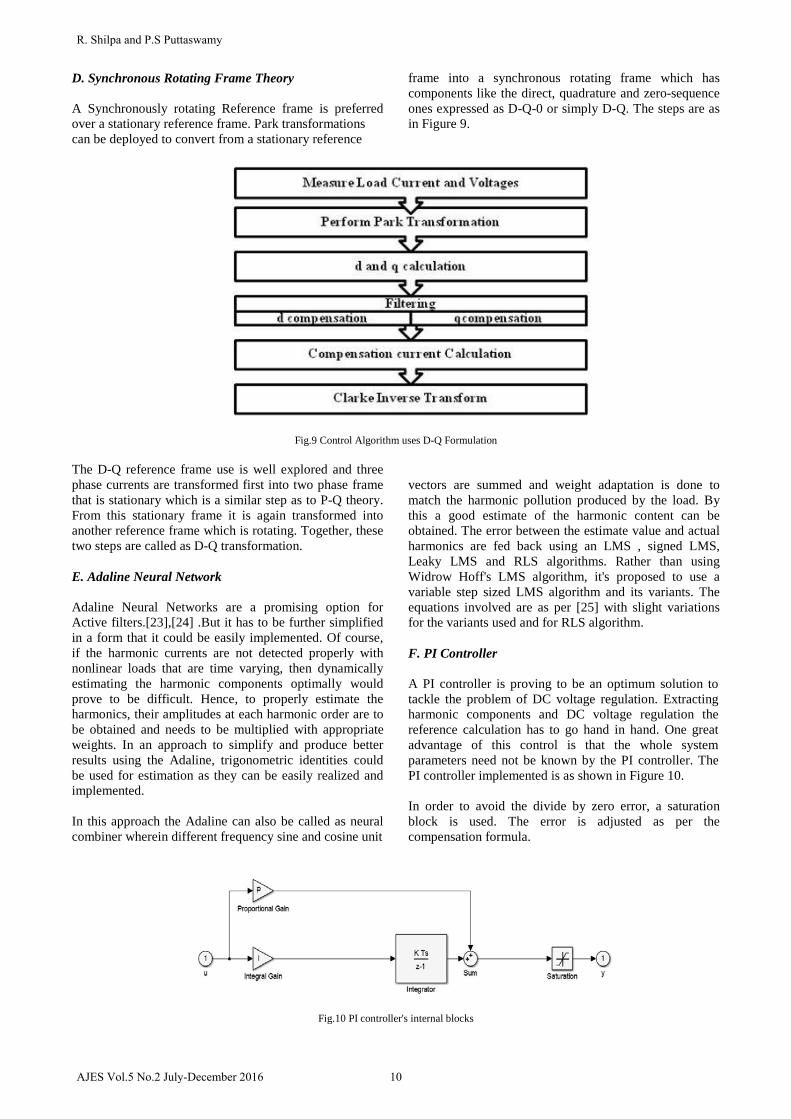
D. Synchronous Rotating Frame Theory A Synchronously rotating Reference frame is preferred over a stationary reference frame. Park transformations can be deployed to convert from a stationary reference
frame into a synchronous rotating frame which has components like the direct, quadrature and zero-sequence ones expressed as D-Q-0 or simply D-Q. The steps are as in Figure 9.
Fig.9 Control Algorithm uses D-Q Formulation The D-Q reference frame use is well explored and three phase currents are transformed first into two phase frame that is stationary which is a similar step as to P-Q theory. From this stationary frame it is again transformed into another reference frame which is rotating. Together, these two steps are called as D-Q transformation. E. Adaline Neural Network Adaline Neural Networks are a promising option for Active filters.[23],[24] .But it has to be further simplified in a form that it could be easily implemented. Of course, if the harmonic currents are not detected properly with nonlinear loads that are time varying, then dynamically estimating the harmonic components optimally would prove to be difficult. Hence, to properly estimate the harmonics, their amplitudes at each harmonic order are to be obtained and needs to be multiplied with appropriate weights. In an approach to simplify and produce better results using the Adaline, trigonometric identities could be used for estimation as they can be easily realized and implemented.
In this approach the Adaline can also be called as neural combiner wherein different frequency sine and cosine unit
vectors are summed and weight adaptation is done to match the harmonic pollution produced by the load. By this a good estimate of the harmonic content can be obtained. The error between the estimate value and actual harmonics are fed back using an LMS , signed LMS, Leaky LMS and RLS algorithms. Rather than using Widrow Hoff's LMS algorithm, it's proposed to use a variable step sized LMS algorithm and its variants. The equations involved are as per [25] with slight variations for the variants used and for RLS algorithm. F. PI Controller A PI controller is proving to be an optimum solution to tackle the problem of DC voltage regulation. Extracting harmonic components and DC voltage regulation the reference calculation has to go hand in hand. One great advantage of this control is that the whole system parameters need not be known by the PI controller. The PI controller implemented is as shown in Figure 10.
In order to avoid the divide by zero error, a saturation block is used. The error is adjusted as per the compensation formula.
Fig.10 PI controller's internal blocks
10AJES Vol.5 No.2 July-December 2016
R. Shilpa and P.S Puttaswamy
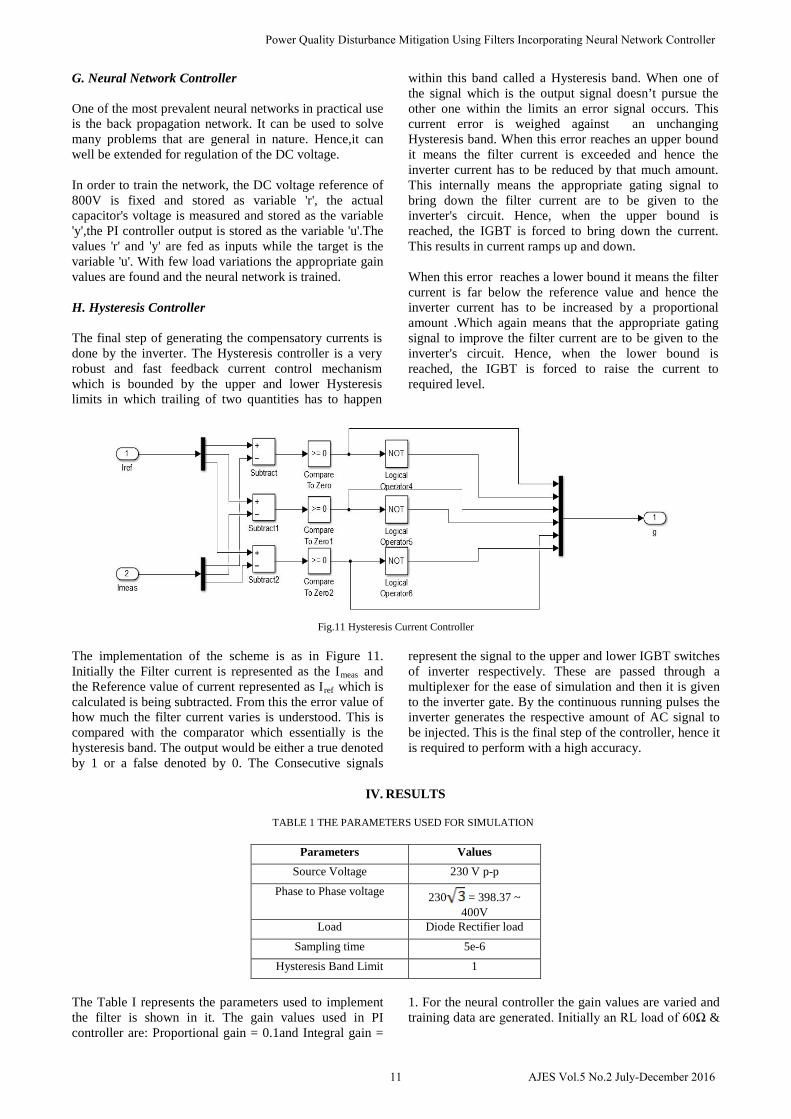
G. Neural Network Controller One of the most prevalent neural networks in practical use is the back propagation network. It can be used to solve many problems that are general in nature. Hence,it can well be extended for regulation of the DC voltage. In order to train the network, the DC voltage reference of 800V is fixed and stored as variable 'r', the actual capacitor's voltage is measured and stored as the variable 'y',the PI controller output is stored as the variable 'u'.The values 'r' and 'y' are fed as inputs while the target is the variable 'u'. With few load variations the appropriate gain values are found and the neural network is trained. H. Hysteresis Controller The final step of generating the compensatory currents is done by the inverter. The Hysteresis controller is a very robust and fast feedback current control mechanism which is bounded by the upper and lower Hysteresis limits in which trailing of two quantities has to happen
within this band called a Hysteresis band. When one of the signal which is the output signal doesn’t pursue the other one within the limits an error signal occurs. This current error is weighed against an unchanging Hysteresis band. When this error reaches an upper bound it means the filter current is exceeded and hence the inverter current has to be reduced by that much amount. This internally means the appropriate gating signal to bring down the filter current are to be given to the inverter's circuit. Hence, when the upper bound is reached, the IGBT is forced to bring down the current. This results in current ramps up and down. When this error reaches a lower bound it means the filter current is far below the reference value and hence the inverter current has to be increased by a proportional amount .Which again means that the appropriate gating signal to improve the filter current are to be given to the inverter's circuit. Hence, when the lower bound is reached, the IGBT is forced to raise the current to required level.
Fig.11 Hysteresis Current Controller The implementation of the scheme is as in Figure 11. Initially the Filter current is represented as the Imeas and the Reference value of current represented as Iref which is calculated is being subtracted. From this the error value of how much the filter current varies is understood. This is compared with the comparator which essentially is the hysteresis band. The output would be either a true denoted by 1 or a false denoted by 0. The Consecutive signals
represent the signal to the upper and lower IGBT switches of inverter respectively. These are passed through a multiplexer for the ease of simulation and then it is given to the inverter gate. By the continuous running pulses the inverter generates the respective amount of AC signal to be injected. This is the final step of the controller, hence it is required to perform with a high accuracy.
IV. RESULTS
TABLE 1 THE PARAMETERS USED FOR SIMULATION
Parameters Values Source Voltage 230 V p-p
Phase to Phase voltage 230 = 398.37 ~ 400V
Load Diode Rectifier load
Sampling time 5e-6
Hysteresis Band Limit 1
The Table I represents the parameters used to implement the filter is shown in it. The gain values used in PI controller are: Proportional gain = 0.1and Integral gain =
1. For the neural controller the gain values are varied and training data are generated. Initially an RL load of 60Ω &
11 AJES Vol.5 No.2 July-December 2016
Power Quality Disturbance Mitigation Using Filters Incorporating Neural Network Controller
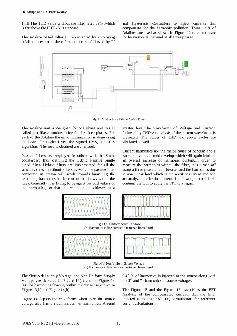
1mH.The THD value without the filter is 28.89% ,which is far above the IEEE- 519 standard. The Adaline based Filter is implemented by employing Adaline to estimate the reference current followed by PI
and Hysteresis Controllers to inject currents that compensate for the harmonic pollution. Three units of Adalines are used as shown in Figure 12 to compensate for harmonics at the level of all three phases.
Fig.12 Adaline based Shunt Active Filter The Adaline unit is designed for one phase and this is called just like a routine thrice for the three phases. For each of the Adaline the error minimization is done using the LMS, the Leaky LMS, the Signed LMS, and RLS algorithms. The results obtained are analyzed. Passive Filters are employed in unison with the Shunt counterpart, thus outlining the Hybrid Passive Single tuned filter. Hybrid filters are implemented for all the schemes shown in Shunt Filters as well. The passive filter connected in unison will work towards banishing the remaining harmonics in the current that flows within the lines. Generally it is fitting to design it for odd values of the harmonics, so that the reduction is achieved at a
greater level.The waveforms of Voltage and Current, followed by THD An analysis of the current waveforms is presented. The values of THD and power factor are tabulated as well. Current harmonics are the major cause of concern and a harmonic voltage could develop which will again leads to an overall increase of harmonic content.In order to measure the harmonics without the filter, it is turned off using a three phase circuit breaker and the harmonics due to non linear load which is the rectifier is measured and are analyzed in the line current. The Powergui block itself contains the tool to apply the FFT to a signal
Fig.13(a) Uniform Source Voltage (b) Harmonics in line currents due to non linear Load
Fig.14(a) Non Uniform Source Voltage (b) Harmonics in line currents due to non linear Load
The Sinusoidal supply Voltage ,and Non Uniform Supply Voltage are depicted in Figure 13(a) and in Figure 14 (a).The harmonics flowing within the current is shown in Figure 13(b) and Figure 14(b). Figure 14 depicts the waveforms when even the source voltage also has a small amount of harmonics. Around
9.43 % of harmonics is injected at the source along with the 5th and 7th harmonics in source voltages. The Figure 15 and the Figure 16 establishes the FFT Analysis of the compensated currents that the filter injected using P-Q and D-Q formulations for reference current calculations.
12AJES Vol.5 No.2 July-December 2016
R. Shilpa and P.S Puttaswamy

Fig.15 FFT Analysis for P-Q theory based Shunt Filter
Fig.16 FFT Analysis for D-Q theory based Shunt Filter
The P-Q theory shows a better reduction of harmonic pollution in the line currents, then the D-Q formulation
based shunt filter for the uniform sinusoidal voltage being applied at the source side.
TABLE 2 THD USING DIFFERENT REFERENCE CALCULATION SCHEMES FOR SHUNT FILTER
Reference Current
Calculation
Sinusoidal Source
Harmonics In Source
Without Compensation 28.59 31.93
P-Q 1.65 9.65
D-Q 4.774 5.31
Adaline – LMS 1.421 1.73
Adaline – Leaky LMS 1.513 1.52
Adaline – Signed LMS 1.389 1.54
Adaline – RLS 1.415 1.45
The overall THD values using different reference current calculation schemes for the Shunt configuration are depicted in Table II.
TABLE 3 THE POWER FACTOR VALUES
Reference Current Calculation
Method
Sinusoidal Source Voltage
Harmonics in Source Voltage
Without Compensation 0.922 0.898
P-Q 0.999 0.989
D-Q 0.999 0.990
Adaline – LMS 0.998 0.994
Adaline – Leaky LMS 0.999 0.995
Adaline – Signed LMS 0.999 0.998
Adaline – RLS 0.998 0.996
13 AJES Vol.5 No.2 July-December 2016
Power Quality Disturbance Mitigation Using Filters Incorporating Neural Network Controller
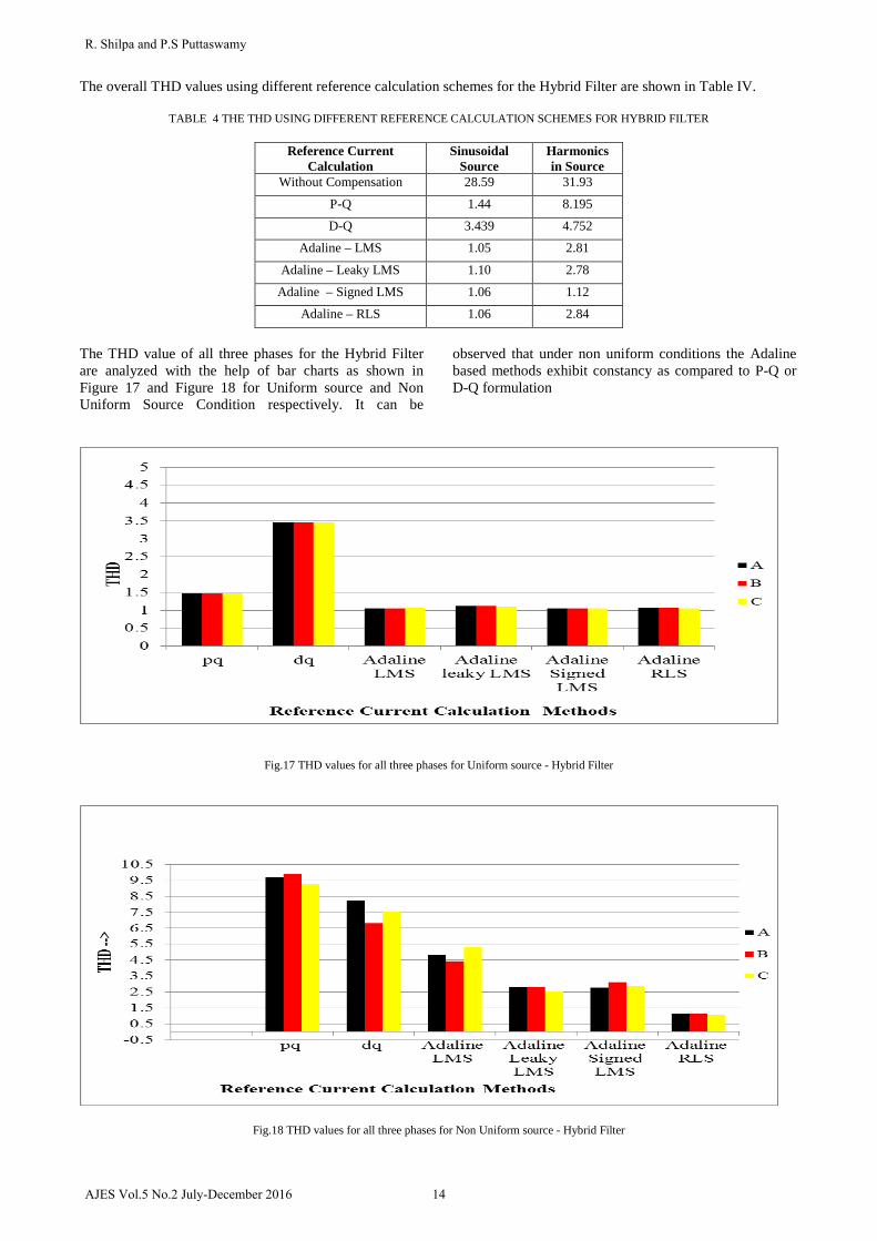
The overall THD values using different reference calculation schemes for the Hybrid Filter are shown in Table IV.
TABLE 4 THE THD USING DIFFERENT REFERENCE CALCULATION SCHEMES FOR HYBRID FILTER
Reference Current Calculation
Sinusoidal Source
Harmonics in Source
Without Compensation 28.59 31.93
P-Q 1.44 8.195
D-Q 3.439 4.752
Adaline – LMS 1.05 2.81
Adaline – Leaky LMS 1.10 2.78
Adaline – Signed LMS 1.06 1.12
Adaline – RLS 1.06 2.84
The THD value of all three phases for the Hybrid Filter are analyzed with the help of bar charts as shown in Figure 17 and Figure 18 for Uniform source and Non Uniform Source Condition respectively. It can be
observed that under non uniform conditions the Adaline based methods exhibit constancy as compared to P-Q or D-Q formulation
Fig.17 THD values for all three phases for Uniform source - Hybrid Filter
Fig.18 THD values for all three phases for Non Uniform source - Hybrid Filter
14AJES Vol.5 No.2 July-December 2016
R. Shilpa and P.S Puttaswamy
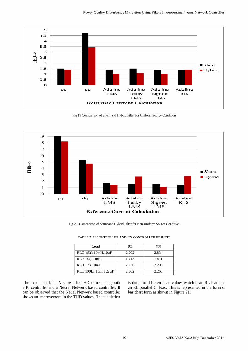
Fig.19 Comparison of Shunt and Hybrid Filter for Uniform Source Condition
Fig.20 Comparison of Shunt and Hybrid Filter for Non Uniform Source Condition
TABLE 5 PI CONTROLLER AND NN CONTROLLER RESULTS
Load PI NN RLC 85Ω,10mH,10µF 2.902 2.834
RL 60 Ω, 1 mH, 1.413 1.411
RL 100Ω 10mH 2.230 2.205
RLC 100Ω 10mH 22µF 2.362 2.268
The results in Table V shows the THD values using both a PI controller and a Neural Network based controller. It can be observed that the Neual Network based controller shows an improvement in the THD values. The tabulation
is done for different load values which is an RL load and an RL parallel C load. This is represented in the form of bar chart form as shown in Figure 21.
15 AJES Vol.5 No.2 July-December 2016
Power Quality Disturbance Mitigation Using Filters Incorporating Neural Network Controller
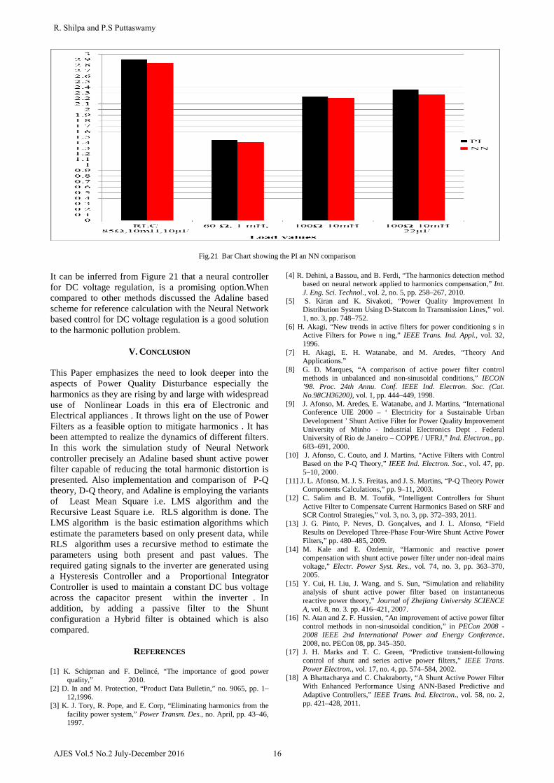
Fig.21 Bar Chart showing the PI an NN comparison It can be inferred from Figure 21 that a neural controller for DC voltage regulation, is a promising option.When compared to other methods discussed the Adaline based scheme for reference calculation with the Neural Network based control for DC voltage regulation is a good solution to the harmonic pollution problem.
V. CONCLUSION
This Paper emphasizes the need to look deeper into the aspects of Power Quality Disturbance especially the harmonics as they are rising by and large with widespread use of Nonlinear Loads in this era of Electronic and Electrical appliances . It throws light on the use of Power Filters as a feasible option to mitigate harmonics . It has been attempted to realize the dynamics of different filters. In this work the simulation study of Neural Network controller precisely an Adaline based shunt active power filter capable of reducing the total harmonic distortion is presented. Also implementation and comparison of P-Q theory, D-Q theory, and Adaline is employing the variants of Least Mean Square i.e. LMS algorithm and the Recursive Least Square i.e. RLS algorithm is done. The LMS algorithm is the basic estimation algorithms which estimate the parameters based on only present data, while RLS algorithm uses a recursive method to estimate the parameters using both present and past values. The required gating signals to the inverter are generated using a Hysteresis Controller and a Proportional Integrator Controller is used to maintain a constant DC bus voltage across the capacitor present within the inverter . In addition, by adding a passive filter to the Shunt configuration a Hybrid filter is obtained which is also compared.
REFERENCES
[1] K. Schipman and F. Delincé, “The importance of good power quality,” 2010.
[2] D. In and M. Protection, “Product Data Bulletin,” no. 9065, pp. 1–12,1996.
[3] K. J. Tory, R. Pope, and E. Corp, “Eliminating harmonics from the facility power system,” Power Transm. Des., no. April, pp. 43–46, 1997.
[4] R. Dehini, a Bassou, and B. Ferdi, “The harmonics detection method based on neural network applied to harmonics compensation,” Int. J. Eng. Sci. Technol., vol. 2, no. 5, pp. 258–267, 2010.
[5] S. Kiran and K. Sivakoti, “Power Quality Improvement In Distribution System Using D-Statcom In Transmission Lines,” vol. 1, no. 3, pp. 748–752.
[6] H. Akagi, “New trends in active filters for power conditioning s in Active Filters for Powe n ing,” IEEE Trans. Ind. Appl., vol. 32, 1996.
[7] H. Akagi, E. H. Watanabe, and M. Aredes, “Theory And Applications.”
[8] G. D. Marques, “A comparison of active power filter control methods in unbalanced and non-sinusoidal conditions,” IECON ’98. Proc. 24th Annu. Conf. IEEE Ind. Electron. Soc. (Cat. No.98CH36200), vol. 1, pp. 444–449, 1998.
[9] J. Afonso, M. Aredes, E. Watanabe, and J. Martins, “International Conference UIE 2000 – ‘ Electricity for a Sustainable Urban Development ’ Shunt Active Filter for Power Quality Improvement University of Minho - Industrial Electronics Dept . Federal University of Rio de Janeiro – COPPE / UFRJ,” Ind. Electron., pp. 683–691, 2000.
[10] J. Afonso, C. Couto, and J. Martins, “Active Filters with Control Based on the P-Q Theory,” IEEE Ind. Electron. Soc., vol. 47, pp. 5–10, 2000.
[11] J. L. Afonso, M. J. S. Freitas, and J. S. Martins, “P-Q Theory Power Components Calculations,” pp. 9–11, 2003.
[12] C. Salim and B. M. Toufik, “Intelligent Controllers for Shunt Active Filter to Compensate Current Harmonics Based on SRF and SCR Control Strategies,” vol. 3, no. 3, pp. 372–393, 2011.
[13] J. G. Pinto, P. Neves, D. Gonçalves, and J. L. Afonso, “Field Results on Developed Three-Phase Four-Wire Shunt Active Power Filters,” pp. 480–485, 2009.
[14] M. Kale and E. Özdemir, “Harmonic and reactive power compensation with shunt active power filter under non-ideal mains voltage,” Electr. Power Syst. Res., vol. 74, no. 3, pp. 363–370, 2005.
[15] Y. Cui, H. Liu, J. Wang, and S. Sun, “Simulation and reliability analysis of shunt active power filter based on instantaneous reactive power theory,” Journal of Zhejiang University SCIENCE A, vol. 8, no. 3. pp. 416–421, 2007.
[16] N. Atan and Z. F. Hussien, “An improvement of active power filter control methods in non-sinusoidal condition,” in PECon 2008 - 2008 IEEE 2nd International Power and Energy Conference, 2008, no. PECon 08, pp. 345–350.
[17] J. H. Marks and T. C. Green, “Predictive transient-following control of shunt and series active power filters,” IEEE Trans. Power Electron., vol. 17, no. 4, pp. 574–584, 2002.
[18] A Bhattacharya and C. Chakraborty, “A Shunt Active Power Filter With Enhanced Performance Using ANN-Based Predictive and Adaptive Controllers,” IEEE Trans. Ind. Electron., vol. 58, no. 2, pp. 421–428, 2011.
16AJES Vol.5 No.2 July-December 2016
R. Shilpa and P.S Puttaswamy
[19] T. D. Rachmildha, “Optimized Combined System of Shunt Active Power Filters and Capacitor Banks,” Int. J. Electr. Eng. Informatics, vol. 3, no. 3, pp. 326–335, 2011.
[20] S. Bangia, P. R. Sharma, and M. Garg, “Comparison of artificial intelligence techniques for the enhancement of power quality,” 2013 Int. Conf. Power, Energy Control, pp. 537–541, 2013.
[21] L. Merabet, S. Saad, D. O. Abdeslam, and a. Omeiri, “A comparative study of harmonic currents extraction by simulation and implementation,” Int. J. Electr. Power Energy Syst., vol. 53, no. 1, pp. 507–514, 2013.
[22] S. Janpong, K. Areerak, and K. Areerak, “A Literature Survey of Neural Network Applications for Shunt Active Power Filters,” pp. 392–398, 2011.
[23] B. V. Ranganadh, A. M. Prasad, and M. Sreedhar, “Modelling And Simulation Of A Hysteresis Band Pulse Width Modulated Current Controller Applied To A Three Phase Voltage Source Inverter By Using Mat lab,” pp. 4378–4387, 2013.
[24] E. H. Watanabe, M. Aredes, and H. Akagi, “The P-Q theory for active filter control: some problems and solutions,” Sba Control. Automação Soc. Bras. Autom., vol. 15, no. 1, pp. 78–84, 2004.
[25] C. Rejil and A. K. R, “Design and Simulation of Three Phase Shunt Active Power Filter Using SRF Theory,” vol. 3, no. 6, pp. 651–660, 2013.
[26] D. O. Abdeslam, P. Wira, J. Merckle, and Y. Chapuis, “A Neural Approach for the Control of an Active Power Filter,” 2005.
[27] D. O. Abdeslam, P. Wira, and D. Flieller, “Active Power Filters,” vol. 54, no. 1, pp. 61–76, 2007.
[28] M. O. Bin Saeed, A. Zerguine, and S. a. Zummo, “Variable step-size least mean square algorithms over adaptive networks,” Proc. ISSPA, no. ISSPA, pp. 381–384, 2010.
[29] KISI, Özgür, and Erdal Uncuoglu. "Comparison of three back-propagation training algorithms for two case studies." Indian journal of engineering & materials sciences 12, no. 5 (2005): 434-442.
[30] A. N. Jog and N. G. Apte, “An adaptive hysteresis band current controlled shunt active power filter,” 5th Int. Conf. Compat. Power Electron. CPE 2007, pp. 8031–8040, 2007.
17 AJES Vol.5 No.2 July-December 2016
Power Quality Disturbance Mitigation Using Filters Incorporating Neural Network Controller