Embed Size (px)
Citation preview
POWER POINT PRESENTATION
ON
HVDC Transmission and FACTS devices
2018 - 2019
IV B. Tech II semester (JNTUH-R15)
Ms. B. Manogna, Assistant Professor
ELECTRICAL AND ELECTRONICS ENGINEERING
INSTITUTE OF AERONAUTICAL ENGINEERING (autonomous)
DUNDIGAL, HYDERABAD - 500 043 1
UNIT –I INTRODUCTION TO HVDC TRANSMISSION SYSTEM
2
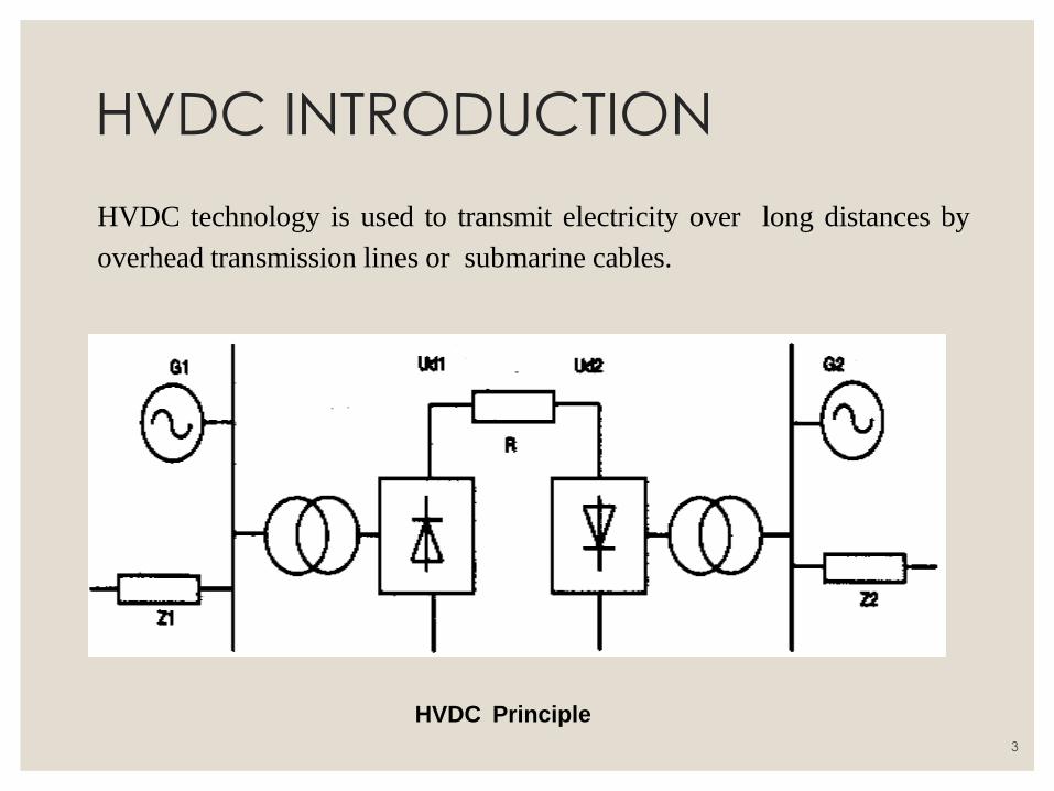
HVDC INTRODUCTION
HVDC technology is used to transmit electricity over long distances by
overhead transmission lines or submarine cables.
HVDC Principle
3
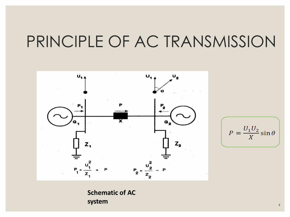
PRINCIPLE OF AC TRANSMISSION
Schematic of AC system
4
REASONS FOR AC GENERATION
AND TRANSMISSION • Due to ease of transformation of voltage levels (simple transformer action)
• Alternating Current is universally utilized.—Both for GENERATION and LOADS
and hence for Transmission.
• Generators are at remote places, away from the populated areas i.e. the load
Centers.
• Turbines drive synchronous generators giving an output at 15-25 kV.
• Voltage is boosted up to 220 or 400 KV by step-up transformers for transmission
to LOADS.
• To reach the loads at homes/industry at required safe levels, transformers step
down voltage
5
COMPARISION OF HVAC &
HVDC SYSTEMS • HVAC transmission is having several limitations like line length , uncontrolled
power flow, over/low voltages during lightly / over loaded conditions, stability problems, fault isolation etc
• The advantage of HVDC is the ability to transmit large amounts of power
over long distances with lower capital costs and with lower losses than AC.
• HVDC transmission allows efficient use of energy sources remote from load
centers. Depending on voltage level and construction details, losses are quoted as about 3% per 1,000 km.
• In a number of applications HVDC is more effective than AC
transmission. Examples include:
• Undersea cables, where high capacitance causes additional AC
losses. (e.g. 250 km Baltic Cable between Sweden and Germany) .
• 600 km NorNed cable between Norway and the Netherlands
6
COMPARISION OF HVAC & HVDC
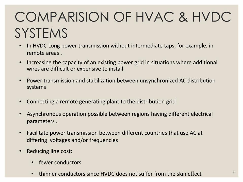
SYSTEMS • In HVDC Long power transmission without intermediate taps, for example, in
remote areas .
• Increasing the capacity of an existing power grid in situations where additional wires are difficult or expensive to install
• Power transmission and stabilization between unsynchronized AC distribution systems
• Connecting a remote generating plant to the distribution grid
• Asynchronous operation possible between regions having different electrical parameters .
• Facilitate power transmission between different countries that use AC at differing voltages and/or frequencies
• Reducing line cost:
• fewer conductors
• thinner conductors since HVDC does not suffer from the skin effect 7
COMPARISION OF HVAC & HVDC SYSTEMS
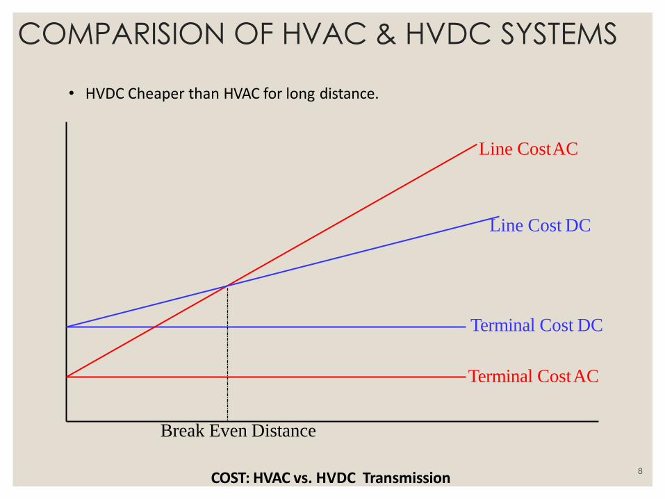
Terminal Cost DC
Terminal Cost AC
Line Cost DC
Break Even Distance
COST: HVAC vs. HVDC Transmission
• HVDC Cheaper than HVAC for long distance.
Line Cost AC
8
COMPARISION OF HVAC & HVDC
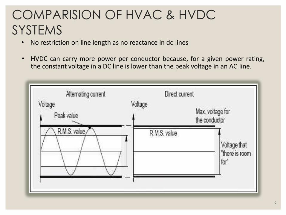
SYSTEMS • No restriction on line length as no reactance in dc lines
• HVDC can carry more power per conductor because, for a given power rating,
the constant voltage in a DC line is lower than the peak voltage in an AC line.
9
COMPARISION OF HVAC & HVDC
SYSTEMS
• HVDC uses less current i.e. low losses.
• AC current will struggle against inertia in the line (100times/sec)-electrical
resistance –inductance- reactive power
• Direct current : Roll along the line ; opposing force friction (electrical resistance )
10
COMPARISION OF HVAC & HVDC
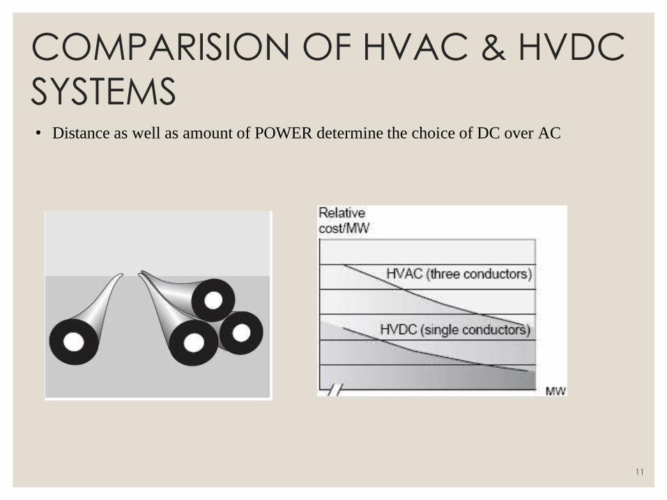
SYSTEMS • Distance as well as amount of POWER determine the choice of DC over AC
11
COMPARISION OF HVAC & HVDC
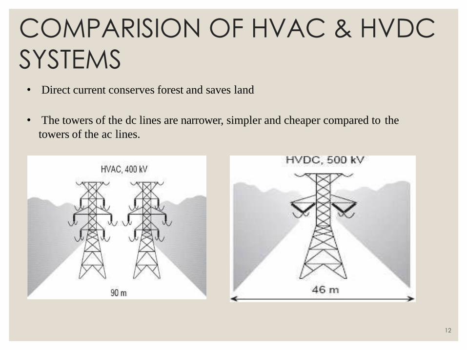
SYSTEMS • Direct current conserves forest and saves land
• The towers of the dc lines are narrower, simpler and cheaper compared to the
towers of the ac lines.
12
COMPARISION OF HVAC & HVDC
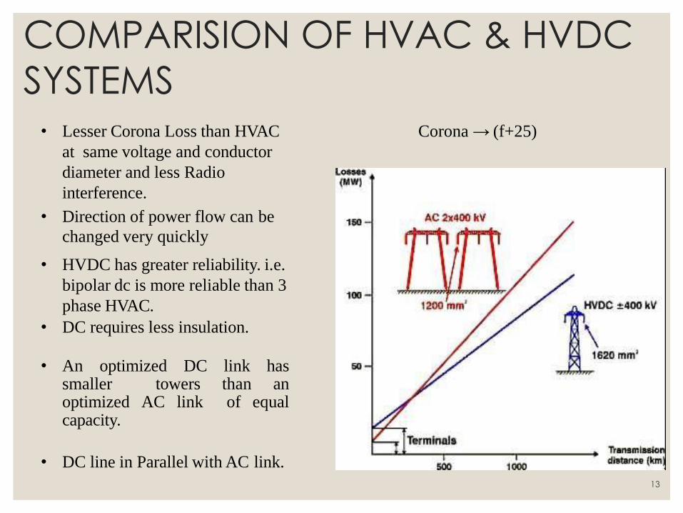
SYSTEMS • Lesser Corona Loss than HVAC
at same voltage and conductor
diameter and less Radio
interference.
• Direction of power flow can be
changed very quickly
• HVDC has greater reliability. i.e.
bipolar dc is more reliable than 3
phase HVAC.
• DC requires less insulation.
• An optimized DC link has
smaller towers than an optimized AC link of equal capacity.
• DC line in Parallel with AC link.
Corona → (f+25)
13
Components of HVDC
Transmission Systems
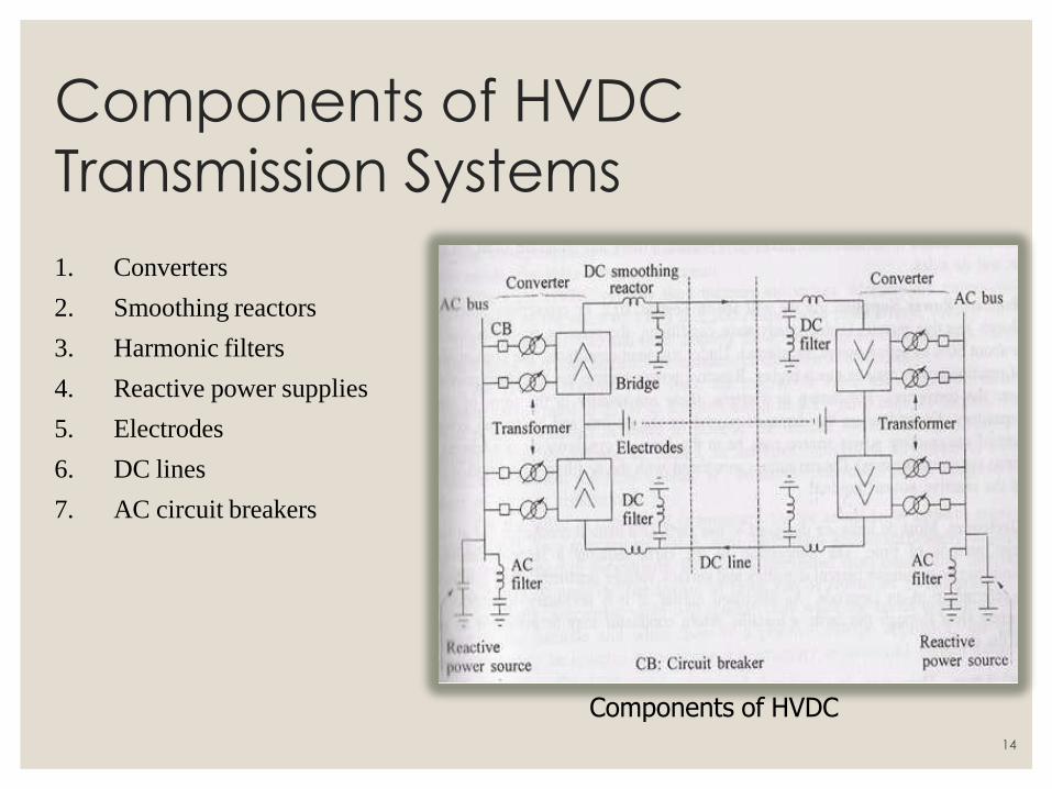
1. Converters
2. Smoothing reactors
3. Harmonic filters
4. Reactive power supplies
5. Electrodes
6. DC lines
7. AC circuit breakers
Components of HVDC
14
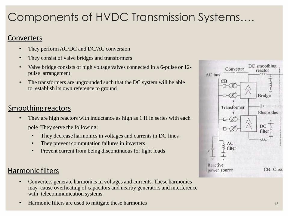
Components of HVDC Transmission Systems….
Converters
• They perform AC/DC and DC/AC conversion
• They consist of valve bridges and transformers
• Valve bridge consists of high voltage valves connected in a 6-pulse or 12-pulse arrangement
• The transformers are ungrounded such that the DC system will be able to establish its own reference to ground
Smoothing reactors • They are high reactors with inductance as high as 1 H in series with each
pole They serve the following:
• They decrease harmonics in voltages and currents in DC lines
• They prevent commutation failures in inverters
• Prevent current from being discontinuous for light loads
Harmonic filters
• Converters generate harmonics in voltages and currents. These harmonics may cause overheating of capacitors and nearby generators and interference with telecommunication systems
• Harmonic filters are used to mitigate these harmonics 15
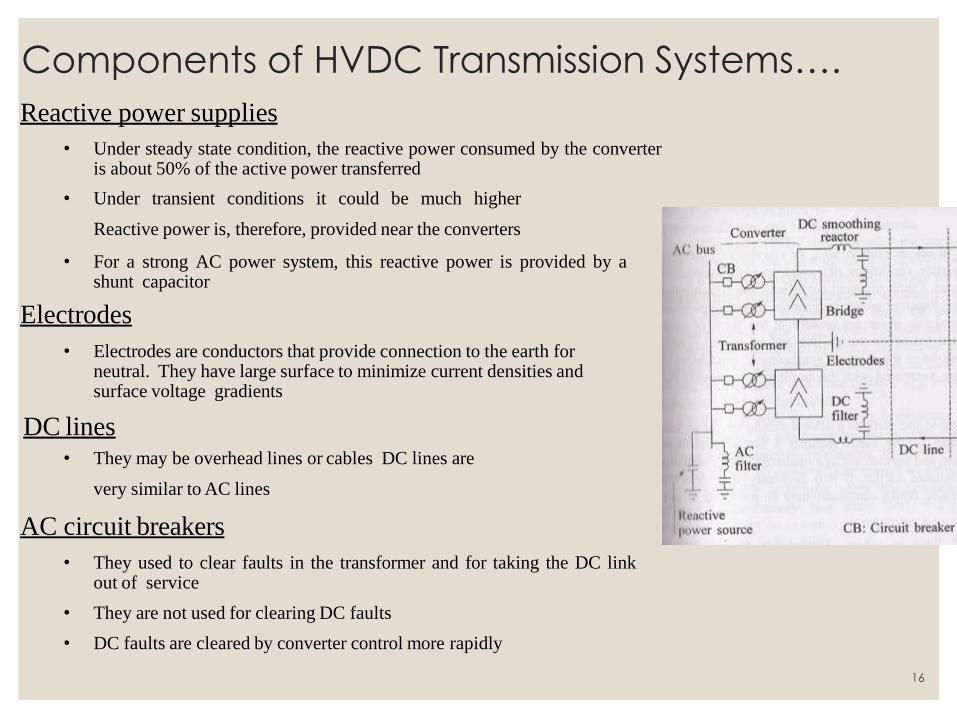
Reactive power supplies
• Under steady state condition, the reactive power consumed by the converter is about 50% of the active power transferred
• Under transient conditions it could be much higher
Reactive power is, therefore, provided near the converters
• For a strong AC power system, this reactive power is provided by a shunt capacitor
Electrodes
• Electrodes are conductors that provide connection to the earth for neutral. They have large surface to minimize current densities and surface voltage gradients
DC lines • They may be overhead lines or cables DC lines are
very similar to AC lines
AC circuit breakers
• They used to clear faults in the transformer and for taking the DC link out of service
• They are not used for clearing DC faults
• DC faults are cleared by converter control more rapidly
Components of HVDC Transmission Systems….
16
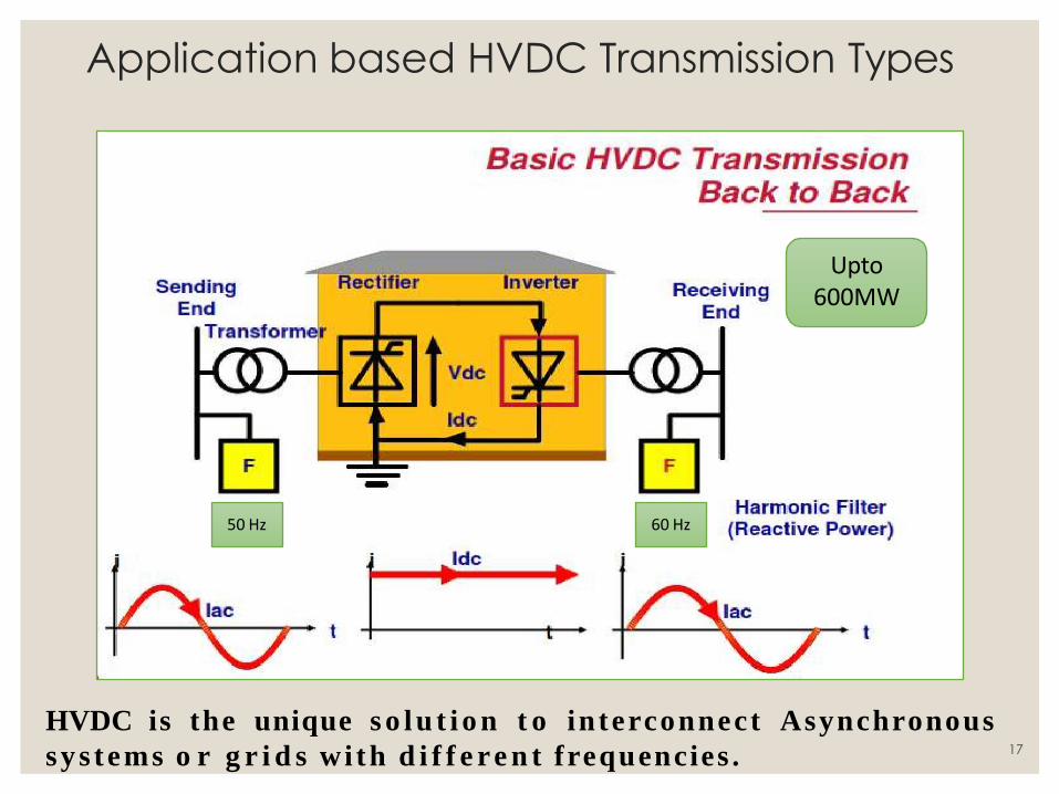
Application based HVDC Transmission Types
Upto 600MW
50 Hz 60 Hz
HVDC is the unique s o l u t i o n t o interconnect Asynchronous
sy s tems o r g r i d s wi th d i f f e re n t frequencies . 17
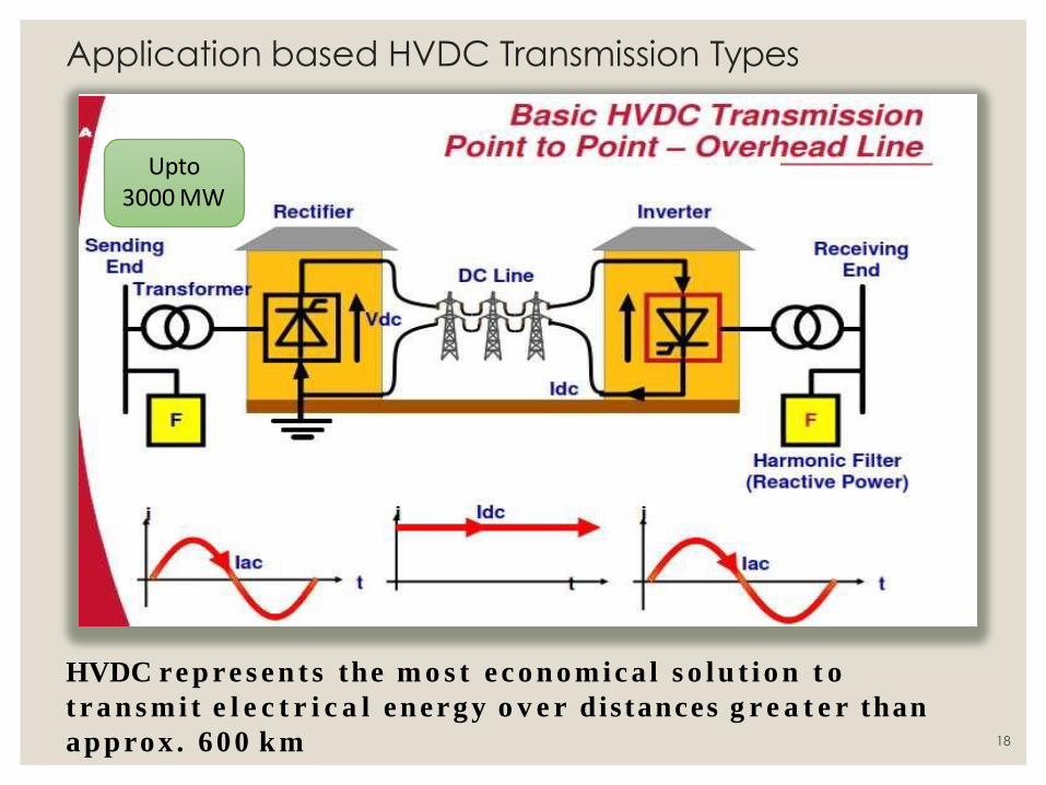
Application based HVDC Transmission Types
Upto 3000 MW
HVDC re p re s e n t s the m o s t e c o n o m ic a l s o l u t i o n t o
t r a n s m i t e l e c t r i c a l en erg y o v e r dis tances g r e a t e r than
a p p ro x . 600 k m 18
HVDC links can be broadly classified into:
• Monopolar links
• Bipolar links
• Homopolar links
• Multiterminal links
HVDC System Configurations
19
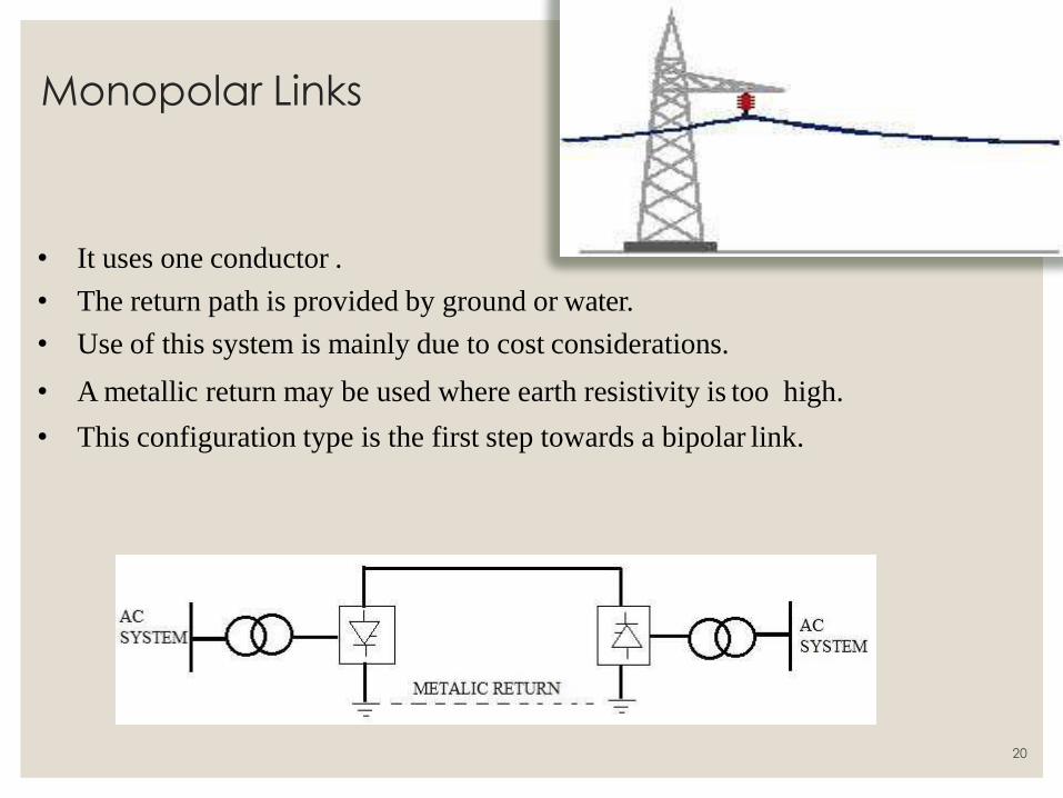
Monopolar Links
• It uses one conductor .
• The return path is provided by ground or water.
• Use of this system is mainly due to cost considerations.
• A metallic return may be used where earth resistivity is too high.
• This configuration type is the first step towards a bipolar link.
20
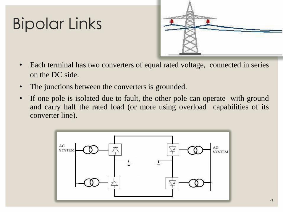
Bipolar Links
• Each terminal has two converters of equal rated voltage, connected in series
on the DC side.
• The junctions between the converters is grounded.
• If one pole is isolated due to fault, the other pole can operate with ground and carry half the rated load (or more using overload capabilities of its converter line).
21
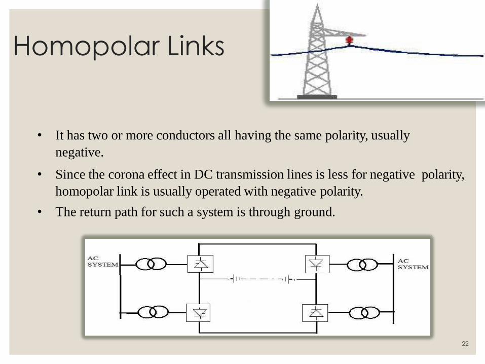
Homopolar Links
• It has two or more conductors all having the same polarity, usually
negative.
• Since the corona effect in DC transmission lines is less for negative polarity,
homopolar link is usually operated with negative polarity.
• The return path for such a system is through ground.
22
Dc as a Means of Transmission DC Transmission has been possible with beginning of
• High power/ high current capability thyristor.
• Fast acting computerized controls
• Convert AC into DC (rectifier)
• Transmit DC
• Convert DC into AC ( inverter)
Since our primary source of power is A.C, The three basic steps are
23
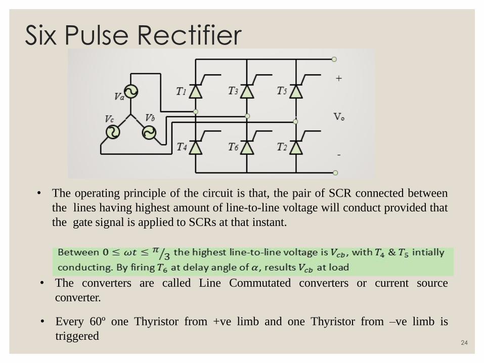
Six Pulse Rectifier
• The operating principle of the circuit is that, the pair of SCR connected between
the lines having highest amount of line-to-line voltage will conduct provided that
the gate signal is applied to SCRs at that instant.
• The converters are called Line Commutated converters or current source
converter.
• Every 60º one Thyristor from +ve limb and one Thyristor from –ve limb is
triggered
24
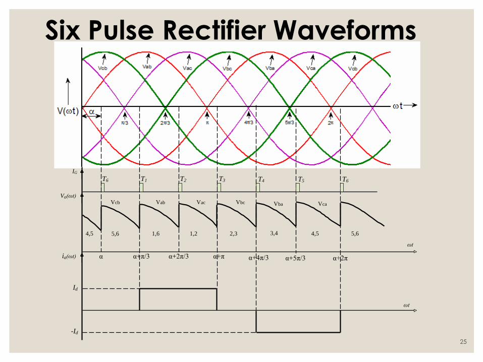
Six Pulse Rectifier Waveforms
Vcb Vab Vac Vbc Vba Vca
α α+π/3 α+2π/3 α+π α+4π/3 α+5π/3 α+2π
Vo(ωt)
ωt
ia(ωt)
ωt
IG
Id
-Id
T6 T1 T2 T3 T4 T5 T6
4,5 1,6 5,6 1,2 2,3 3,4 4,5 5,6
25
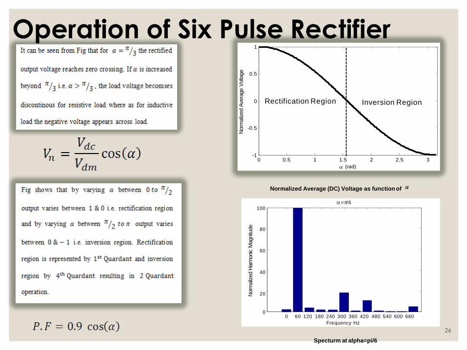
Operation of Six Pulse Rectifier
0 0.5 1 2 2.5 3 -1
-0.5
0.5
1
1.5
(rad)
Norm
aliz
ed A
vera
ge V
olta
ge
0 Rectification Region Inversion Region
0
Normalized Average (DC) Voltage as function of
= /6
100
80
60
40
20
0 60 120 180 240 300 360 420 480 540 600 660
Frequency Hz
Norm
aliz
ed H
arm
onic
Magnitu
de
Specturm at alpha=pi/6
26
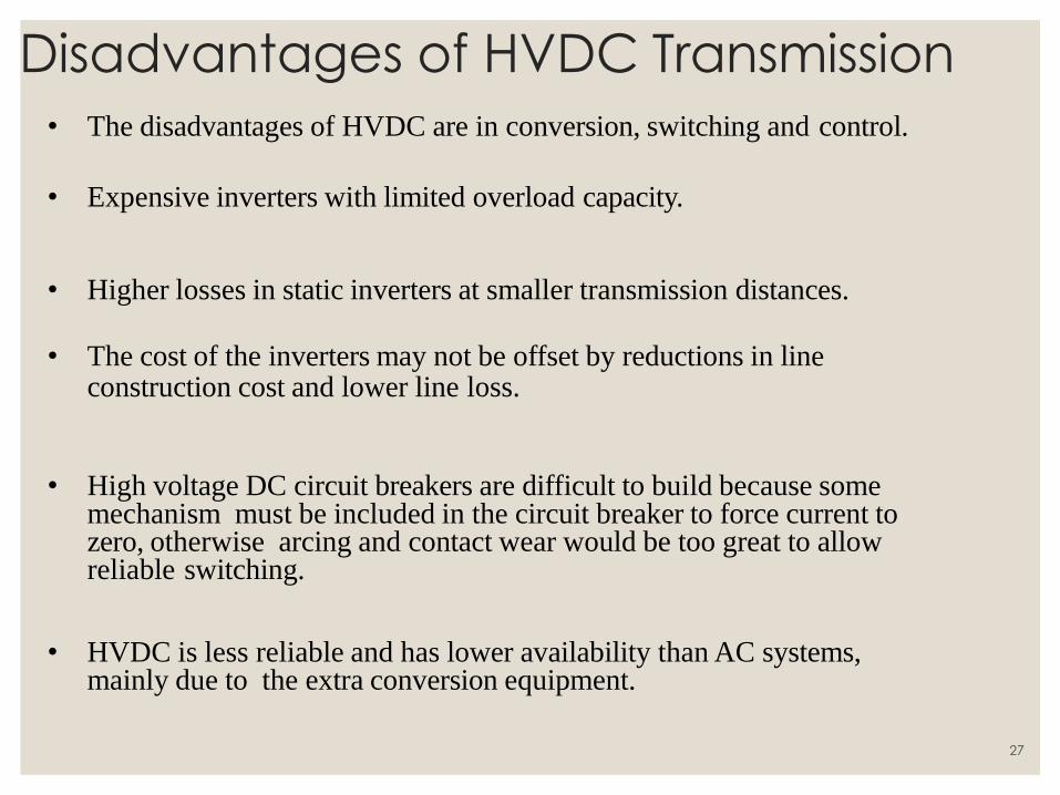
Disadvantages of HVDC Transmission
• The disadvantages of HVDC are in conversion, switching and control.
• Expensive inverters with limited overload capacity.
• Higher losses in static inverters at smaller transmission distances.
• The cost of the inverters may not be offset by reductions in line
construction cost and lower line loss.
• High voltage DC circuit breakers are difficult to build because some
mechanism must be included in the circuit breaker to force current to zero, otherwise arcing and contact wear would be too great to allow reliable switching.
• HVDC is less reliable and has lower availability than AC systems, mainly due to the extra conversion equipment.
27
UNIT-II CONVERTER AND HVDC CONTROL SYSTEM
28
Control of HVDC Systems
Objectives of
Control
• Principle of operation of various
control systems.
• Implementation and their performance
during normal and abnormal system
conditions.
Content
• Efficient and stable operation.
• Maximum flexibility of power control
without compromising the safety of
equipment.
29
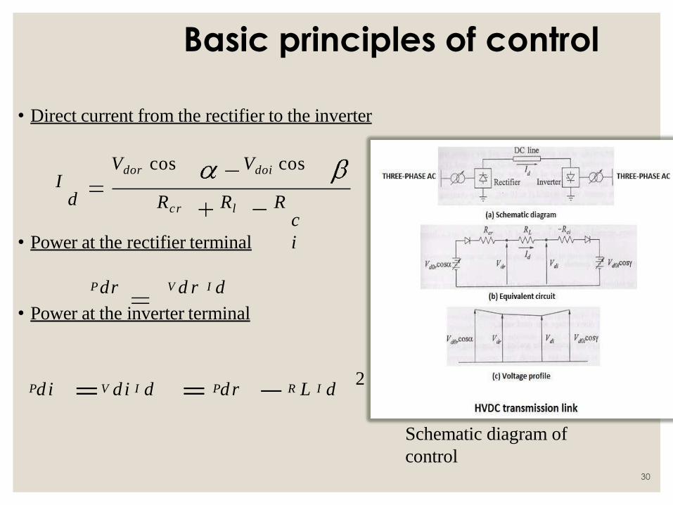
Basic principles of control
• Direct current from the rectifier to the inverter
c
i
d Rcr Rl R I
Vdor cos Vdoi cos
• Power at the rectifier terminal
Pdr V d r I d
• Power at the inverter terminal
2 Pd i V d i I d Pdr R L I d
Schematic diagram of
control 30

Basic Means of control
◦ control the voltages at any point on the line and the current flow
(power).
◦ This can be accomplished by:
◦ Controlling firing angles of the rectifier and inverter
(for fast action).
◦ Changing taps on the transformers on the AC
side (slow response).
◦ Power reversal is obtained by reversal of polarity of direct
voltages
◦ at both ends.
and can used be controlled to • Internal voltages Vdor cos Vdoi cos
31
BASIC MEANS CONTROL
◦ control the voltages at any point on the line and the current flow
(power).
◦ This can be accomplished by:
◦ Controlling firing angles of the rectifier and inverter
(for fast action).
◦ Changing taps on the transformers on the AC
side (slow response).
◦ Power reversal is obtained by reversal of polarity of direct
voltages
◦ at both ends.
and can used be controlled to • Internal voltages Vdor cos Vdoi cos
32
Basic Means of control
◦ control the voltages at any point on the line and the current flow
(power).
◦ This can be accomplished by:
◦ Controlling firing angles of the rectifier and inverter
(for fast action).
◦ Changing taps on the transformers on the AC
side (slow response).
◦ Power reversal is obtained by reversal of polarity of direct
voltages
◦ at both ends.
and can used be controlled to • Internal voltages Vdor cos Vdoi cos
33
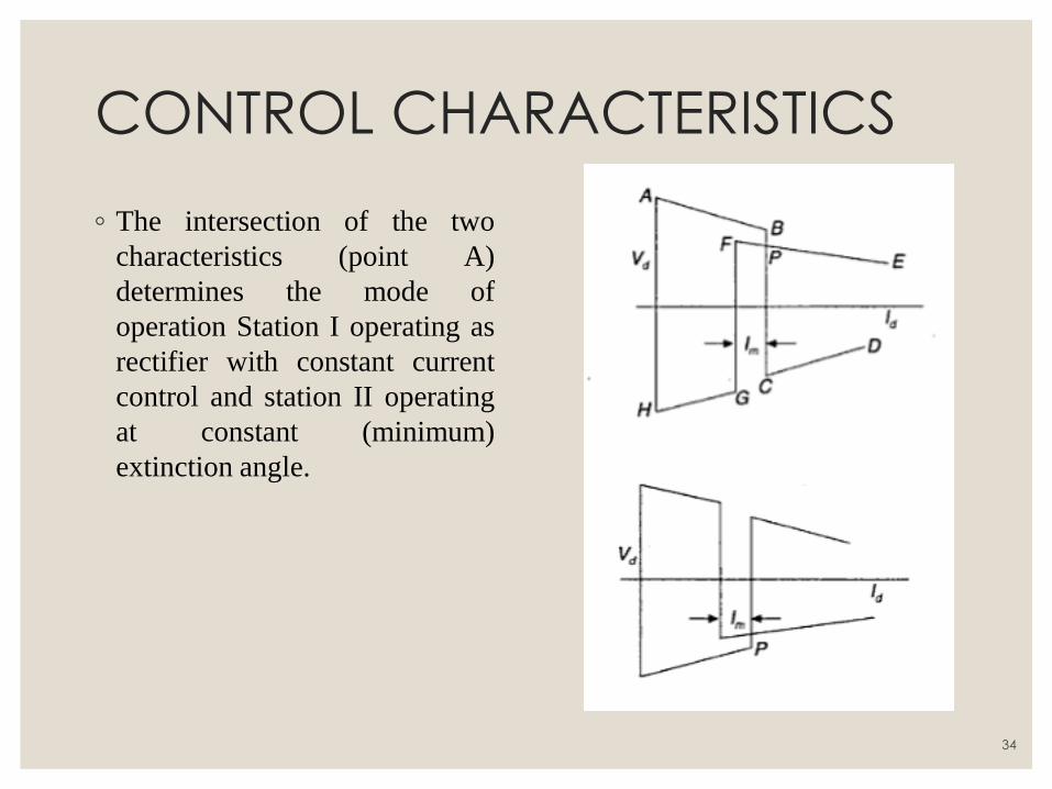
CONTROL CHARACTERISTICS
◦ The intersection of the two
characteristics (point A)
determines the mode of
operation Station I operating as
rectifier with constant current
control and station II operating
at constant (minimum)
extinction angle.
34
CONTROL CHARACTERISTICS
◦ There can be three modes of operation of the link (for the same
direction of power flow) depending on the ceiling voltage of the
rectifier which determines the point of intersection of the two
characteristics which are defined below:
1. CC at rectifier and CEA at inverter (operating point A) which is the
normal mode of operation.
2. With slight dip in the AC voltage, the point of intersection drifts to
C which implies minimum α at rectifier and minimum γ at the
inverter.
3. With lower AC voltage at the rectifier, the mode of operation shifts
to point B which implies CC at the inverter with minimum α at the
rectifier.
35
Introduction to facts
◦ Flexible alternating current transmission system.
◦ Facts as they are generally known, are new devices that improve transmission
systems.
◦ Facts is a static equipment used for the ac transmission of electrical energy.
◦ It is generally a power electronics based device.
◦ Meant to enhance controllability and increase power transfer capability.
36
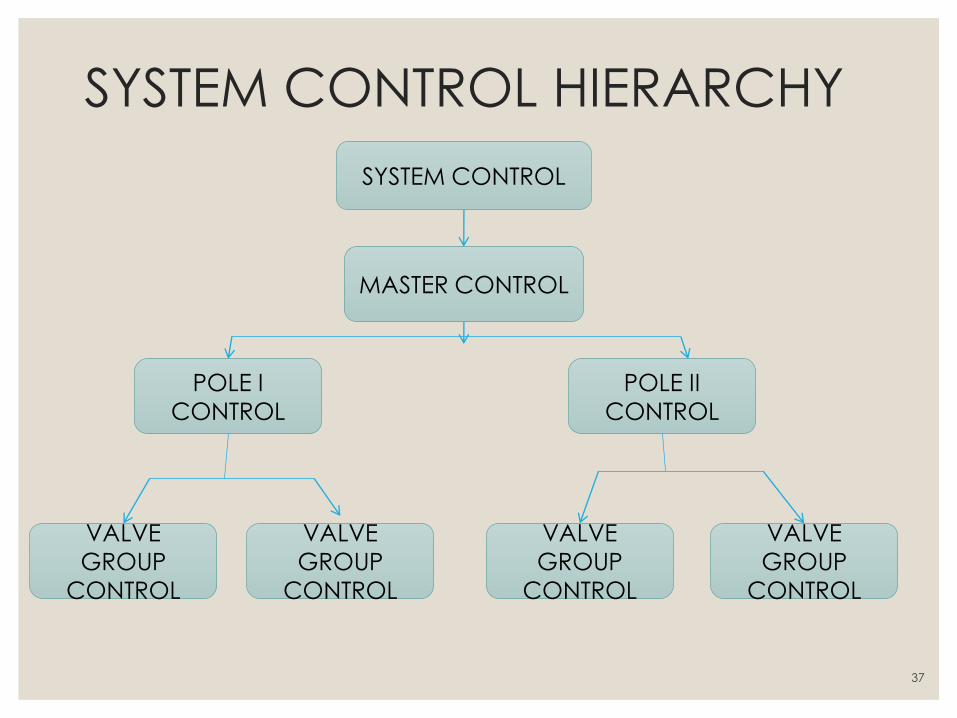
SYSTEM CONTROL HIERARCHY
SYSTEM CONTROL
MASTER CONTROL
POLE I
CONTROL
POLE II
CONTROL
VALVE
GROUP
CONTROL
VALVE
GROUP
CONTROL
VALVE
GROUP
CONTROL
VALVE
GROUP
CONTROL
37
◦ The master controller for a bipole is located at one of the terminals and is
provided with the power order (Pref ) from the system controller (from energy
control centre). It also has other information such as AC voltage at the
converter bus, DC voltage etc. The master controller transmits the current order
(Iref ) to the pole control units which in turn provide a firing angle order to the
individual valve groups (converters). The valve group or converter control also
oversees valve monitoring and firing logic through the optical interface. It also
includes bypass pair selection logic, commutation failure protection, tap
changer control, converter start/stop sequences, margin switching and valve
protection circuits. The pole control incorporated pole protection, DC line
protection and optional converter paralleling and deparalleling sequences. The
master controller which oversees the complete bi-pole includes the functions of
frequency control, power modulation, AC voltage and reactive power control
and torsional frequency damping control.
SYSTEM CONTROL HIERARCHY
38
FIRING ANGLE CONTROL ◦ The operation of CC and CEA controllers is closely linked with the method of
generation of gate pulses for the valves in a converter. The requirements for the
firing pulse generation of HVDC valves are
◦ The firing instant for all the valves are determined at ground potential and the firing
signals sent to individual thyristors by light signals through fibre-optic cables. The
required gate power is made available at the potential of individual thyristor.
◦ While a single pulse is adequate to turn-on a thyristor, the gate pulse generated must
send a pulse whenever required, if the particular valve is to be kept in a conducting
state.
◦ The two basic firing schemes are
◦ Individual Phase Control (IPC)
◦ Equidistant Pulse Control (EPC)
39
INDIVIDUAL PHASE CONTROL
This was used in the early HVDC projects. The main feature of this
scheme is that the firing pulse generation for each phase (or valve) is
independent of each other and the firing pulses are rigidly synchronized
with commutation voltages.
◦ There are two ways in which this can be achieved
◦ Constant α Control
◦ Inverse Cosine Control
40
INDIVIDUAL PHASE CONTROL
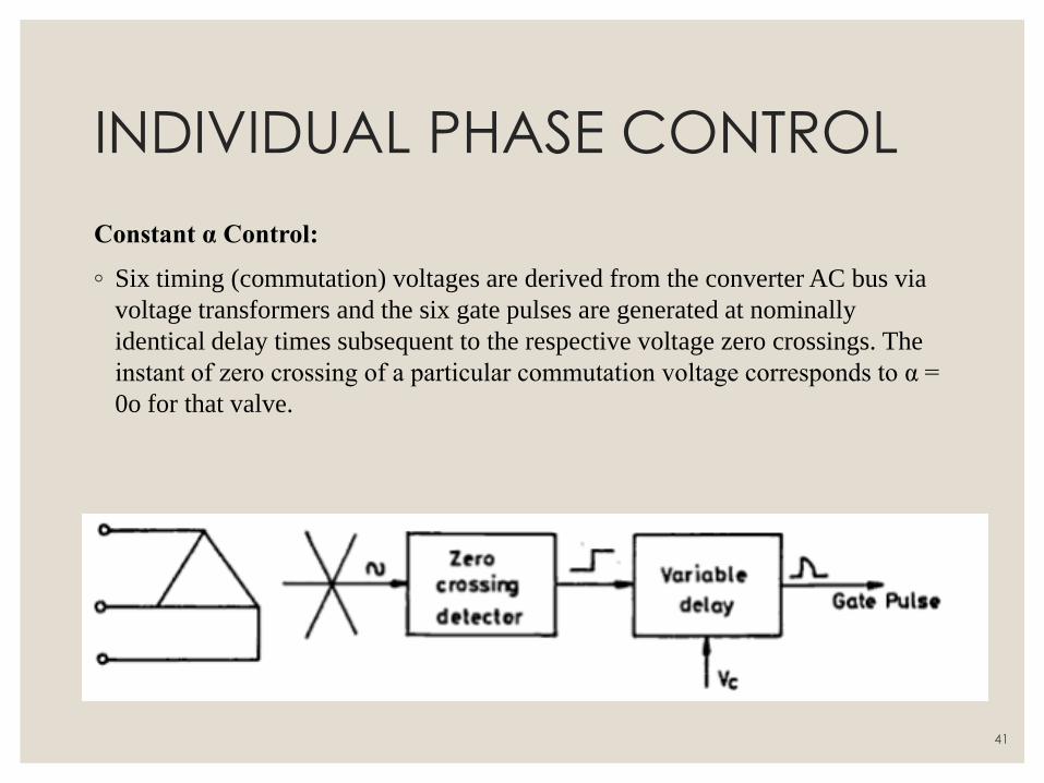
Constant α Control:
◦ Six timing (commutation) voltages are derived from the converter AC bus via
voltage transformers and the six gate pulses are generated at nominally
identical delay times subsequent to the respective voltage zero crossings. The
instant of zero crossing of a particular commutation voltage corresponds to α =
0o for that valve.
41
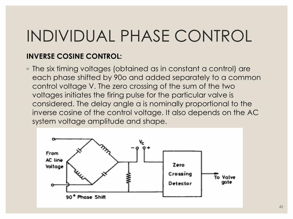
INDIVIDUAL PHASE CONTROL INVERSE COSINE CONTROL:
◦ The six timing voltages (obtained as in constant α control) are
each phase shifted by 90o and added separately to a common
control voltage V. The zero crossing of the sum of the two
voltages initiates the firing pulse for the particular valve is
considered. The delay angle α is nominally proportional to the
inverse cosine of the control voltage. It also depends on the AC
system voltage amplitude and shape.
42
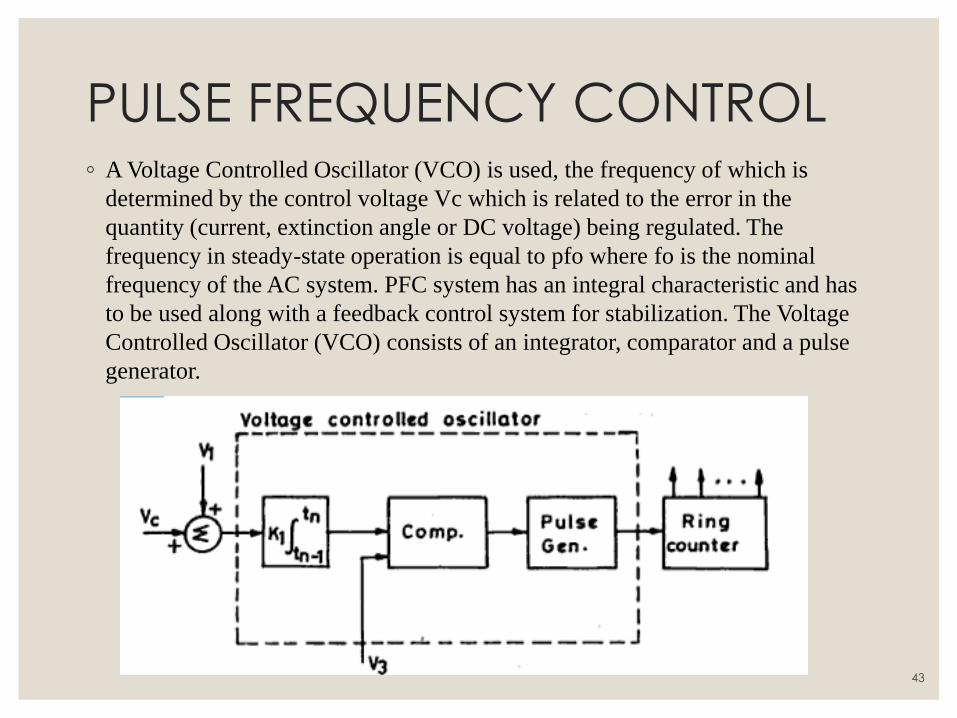
PULSE FREQUENCY CONTROL ◦ A Voltage Controlled Oscillator (VCO) is used, the frequency of which is
determined by the control voltage Vc which is related to the error in the
quantity (current, extinction angle or DC voltage) being regulated. The
frequency in steady-state operation is equal to pfo where fo is the nominal
frequency of the AC system. PFC system has an integral characteristic and has
to be used along with a feedback control system for stabilization. The Voltage
Controlled Oscillator (VCO) consists of an integrator, comparator and a pulse
generator.
43
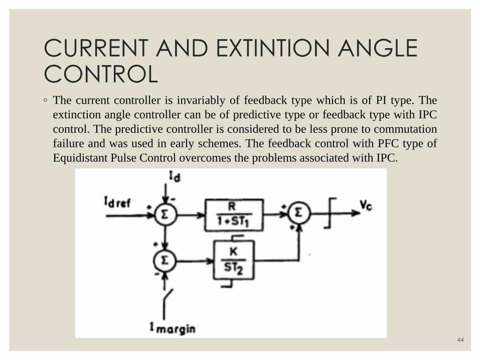
CURRENT AND EXTINTION ANGLE CONTROL ◦ The current controller is invariably of feedback type which is of PI type. The
extinction angle controller can be of predictive type or feedback type with IPC
control. The predictive controller is considered to be less prone to commutation
failure and was used in early schemes. The feedback control with PFC type of
Equidistant Pulse Control overcomes the problems associated with IPC.
44
STARTING AND STOPPING OF DC LINK ◦ Energization and Deenergization of a Bridge: Consider N series connected
bridges at a converter station. If one of the bridges is to be taken out of service,
there is need to not only block, but bypass the bridge. This is because of the
fact that just blocking the pulses does not extinguish the current in the pair of
valves that are left conducting at the time of blocking. The continued
conduction of this pair injects AC voltage into the link which can give rise to
current and voltage oscillations due to lightly damped oscillatory circuit in the
link formed by smoothing reactor and the line capacitance. The transformer
feeding the bridge is also subjected to DC magnetization when DC current
continues to flow through the secondary windings. The bypassing of the bridge
can be done with the help of a separate bypass valve or by activating a bypass
pair in the bridge (two valves in the same arm of the bridge). The bypass valve
was used with mercury arc valves where the possibility of arc backs makes it
impractical to use bypass pairs. With thyristor valves, the use of bypass pair is
the practice as it saves the cost of an extra valve.
45
STARTUP OF DC LINK ◦ Start-up with long pulse firing:
1. De block inverter at about γ =
900
2. De block rectifier at α = 850
to establish low direct current
3. Ramp up voltage by inverter
control and the current by
rectifier control.
◦ Start-up with short pulse firing:
1. Open bypass switch at one
terminal
2. Deblock that terminal and
load to minimum current in
the rectifier mode
3. Open bypass switch at the
second terminal and
commutate current to the
bypass pair
4. Start the second terminal
also in the rectifier mode
5. The inverter terminal is put
into the inversion mode
6. Ramp up voltage and
current.
46
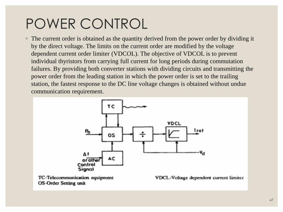
POWER CONTROL ◦ The current order is obtained as the quantity derived from the power order by dividing it
by the direct voltage. The limits on the current order are modified by the voltage
dependent current order limiter (VDCOL). The objective of VDCOL is to prevent
individual thyristors from carrying full current for long periods during commutation
failures. By providing both converter stations with dividing circuits and transmitting the
power order from the leading station in which the power order is set to the trailing
station, the fastest response to the DC line voltage changes is obtained without undue
communication requirement.
47
UNIT III FILTERS AND POWER FLOW ANALYSIS
48
INTRODUCTION TO HARMONICS
◦ An HVDC transmission system generates harmonic currents on the AC side
and harmonic voltages on the DC side during operation. The harmonic currents
generated at the AC bus of the converter get transmitted to the AC network and
then cause the following adverse effects.
1. Heating of the equipments connected.
2. Instability of converter control.
3. Generates telephone and radio interference in adjacent communication lines,
thereby inducing harmonic noise.
4. Harmonics can lead to generation of over voltages due to resonance when filter
circuits are employed.
49
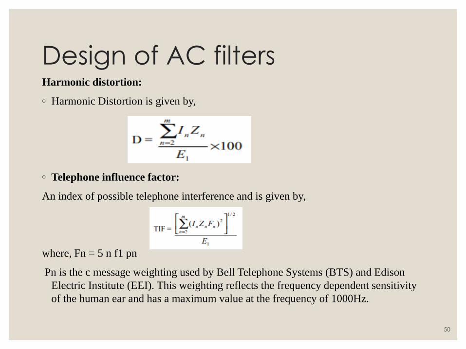
Design of AC filters Harmonic distortion:
◦ Harmonic Distortion is given by,
◦ Telephone influence factor:
An index of possible telephone interference and is given by,
where, Fn = 5 n f1 pn
Pn is the c message weighting used by Bell Telephone Systems (BTS) and Edison
Electric Institute (EEI). This weighting reflects the frequency dependent sensitivity
of the human ear and has a maximum value at the frequency of 1000Hz.
50
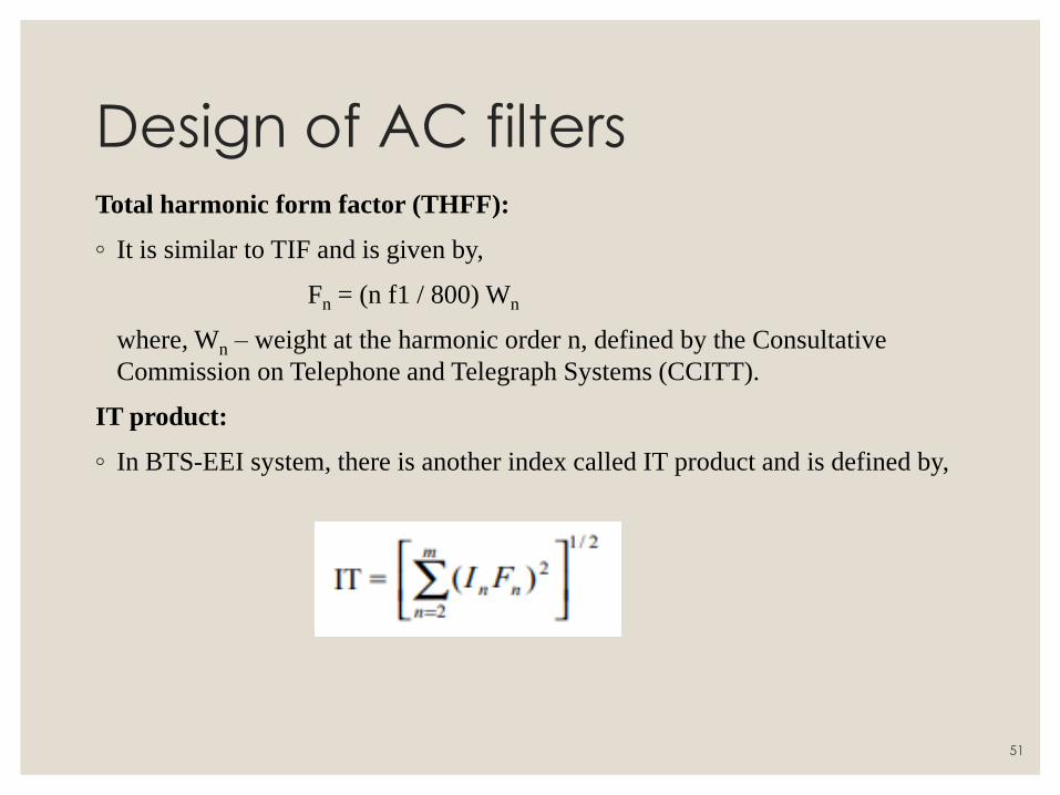
Design of AC filters Total harmonic form factor (THFF):
◦ It is similar to TIF and is given by,
Fn = (n f1 / 800) Wn
where, Wn – weight at the harmonic order n, defined by the Consultative
Commission on Telephone and Telegraph Systems (CCITT).
IT product:
◦ In BTS-EEI system, there is another index called IT product and is defined by,
51
Types of AC filters:
◦ The various types of filters that are used are
◦ Single Tuned Filter
◦ Double Tuned Filter
◦ High Pass Filter
1. Second Order Filter
2. C Type Filter
52
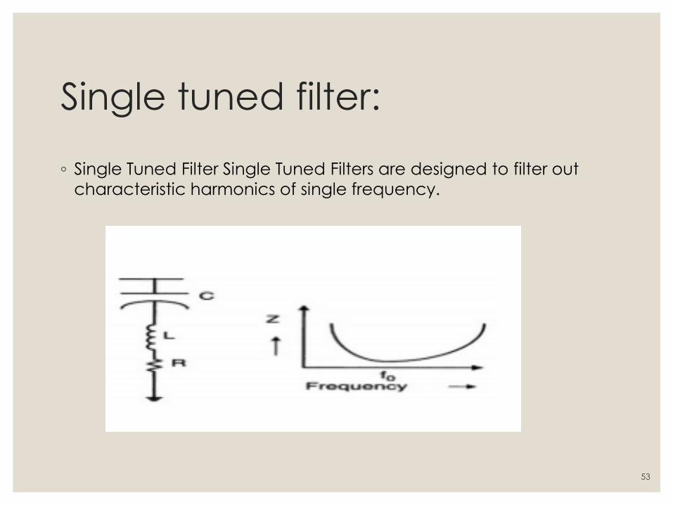
Single tuned filter:
◦ Single Tuned Filter Single Tuned Filters are designed to filter out
characteristic harmonics of single frequency.
53
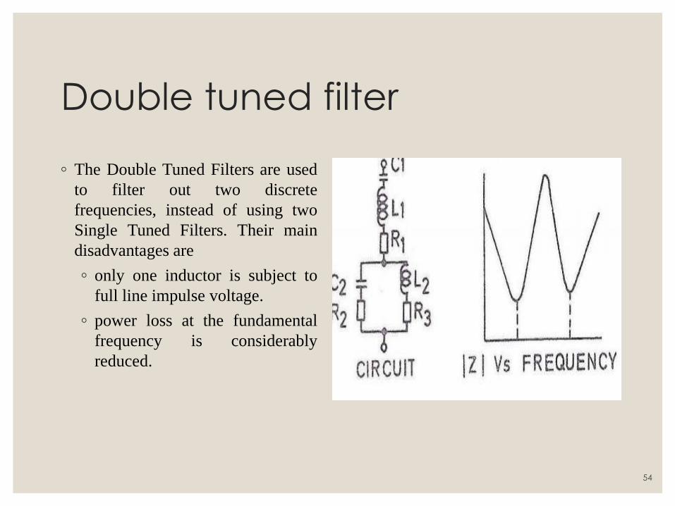
Double tuned filter
◦ The Double Tuned Filters are used
to filter out two discrete
frequencies, instead of using two
Single Tuned Filters. Their main
disadvantages are
◦ only one inductor is subject to
full line impulse voltage.
◦ power loss at the fundamental
frequency is considerably
reduced.
54
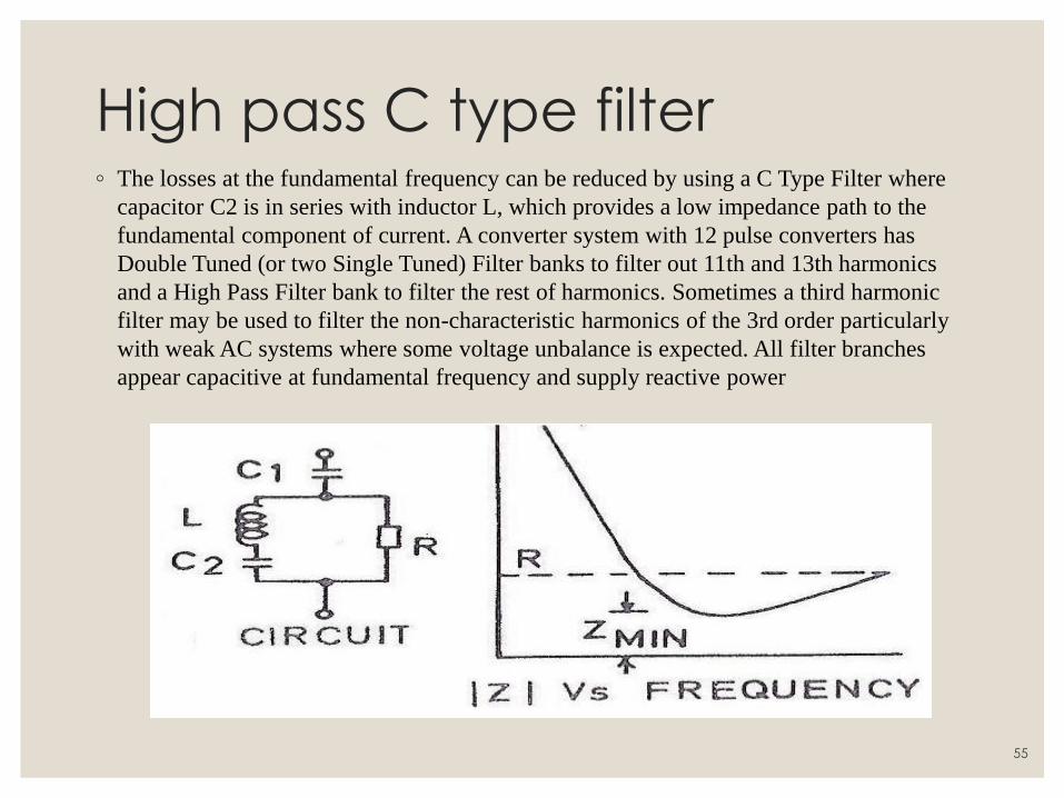
High pass C type filter ◦ The losses at the fundamental frequency can be reduced by using a C Type Filter where
capacitor C2 is in series with inductor L, which provides a low impedance path to the
fundamental component of current. A converter system with 12 pulse converters has
Double Tuned (or two Single Tuned) Filter banks to filter out 11th and 13th harmonics
and a High Pass Filter bank to filter the rest of harmonics. Sometimes a third harmonic
filter may be used to filter the non-characteristic harmonics of the 3rd order particularly
with weak AC systems where some voltage unbalance is expected. All filter branches
appear capacitive at fundamental frequency and supply reactive power
55
Requirment of ratings: Steady state calculation:
◦ The voltage and current stresses of
AC filters consist of the
fundamental frequency and
harmonic components. Their
magnitudes depend on the AC
system voltage, harmonic currents,
operating conditions and AC
system impedances. The rating
calculations are carried out in the
whole range of operation to
determine the highest steady-state
current and voltage stresses for
each individual filter component.
Transient Calculation:
◦ The objective of the transient rating
calculation is to determine the
highest transient stresses for each
component of the designed filter
arrangement. The results of the
transient calculation should contain
the voltage and current stresses for
each component, energy duty for
filter resistors and arresters, and the
insulation levels for each filter
component.
56
Requirement of ratings: To calculate the highest stresses of both lightning and switching surge type,
different circuit configurations and fault cases should be studied.
Single-Phase GroundFault
◦ The fault is applied on the converter AC bus next to the AC filter. It is
assumed that the filter capacitor is charged to a voltage level corresponding
to the switching impulse protective level of the AC busarrester.
Switching Surge
◦ For the calculation of switching surge stresses, a standard wave of 250/2500
with a crest value equal to the switching impulse protective level of the AC
bus arrester is applied at the AC converterbus.
57
Dc filter circuits:
◦ Harmonic voltages which occur on the DC side of a converter station cause AC
currents which are superimposed on the direct current in the transmission line.
These alternating currents of higher frequencies can create interference in
neighboring telephone systems despite limitation by smoothing reactors. DC
filter circuits, which are connected in parallel to the station poles, are an
effective tool for combating these problems. The configuration of the DC filters
very strongly resembles the filters on the AC side of the HVDC station. There
are several types of filter design. Single and multiple-tuned filters with or
without the high-pass feature are common. One or several types of DC filter
can be utilized in a converter station.
58
Protection of filters:
◦ The filter is exposed to overvoltage during switching in and the magnitude of
this overvoltage is a function of the short-circuit ratio (higher with low values
of SCR) and the saturation characteristics of the converter transformer. During
switching in, the filter current (at filter frequencies) can have magnitudes
ranging from 20 to 100 times the harmonic current in normal (steady-state)
operation. The lower values for tuned filters and higher values are applicable to
high pass filters. These over currents are taken into consideration in the
mechanical design of reactor coils. When filters are disconnected, their
capacitors remain charged to the voltage at the instant of switching. The
residual direct voltages can also occur on bus bars. To avoid, the capacitors
may be discharged by short-circuiting devices or through converter
transformers or by voltage transformers loaded with resistors.
59

UNIT IV INTRODUCTION TO FACTS
60
FLEXIBLE AC TRANSMISSION SYSTEM
◦ FACTS
AC transmission systems incorporating the power electronic-based to enhance controllability and increase power transfer capability.
◦ FACTS Controllers
A power electronic based system & other static equipment that provide control of one or more AC transmission parameters.
61
BENEFITS OF USING FACTS
◦ Better utilization of existing transmission system assets
◦ Increased transmission system reliability and availability (lower
vulnerability to load changes, line faults)
◦ Increased dynamic and transient grid
◦ Stability and reduction of loop flows
◦ Increased quality of supply for sensitive industries (through mitigation
of flicker, frequency variations)
◦ Environmental benefits
62
Power factor correction:
◦ The amount of Power Capacitor KVAR required to correct A system to a
desired Power Factor level is the difference between the amount of KVAR in
the uncorrected system and the amount of desired KVAR in the corrected
system. The most efficient location for power factor capacitors is at the load.
Capacitors work from the point of installation back to the generating source.
Individual motor correction is not always practical, sometimes it is more
practical to connect larger capacitors on the distribution bus or install an
automatic system at the incoming service along with fixed capacitors at the
load.
63
Power factor correction techniques:
◦ Static VAR Compensator(SVC) •
◦ Fixed Capcitors
◦ Switch Capacitors
◦ Synchronous Condensors
◦ Static Synchronous Compensator(STATCOM)
◦ Modulated power filter capacitor compensator
64
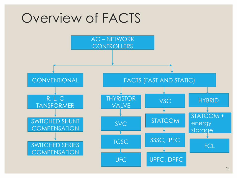
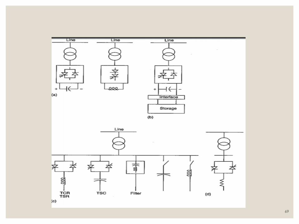
Overview of FACTS
AC – NETWORK
CONTROLLERS
CONVENTIONAL FACTS (FAST AND STATIC)
R, L, C
TANSFORMER
SWITCHED SHUNT
COMPENSATION
SWITCHED SERIES
COMPENSATION
THYRISTOR
VALVE
SVC
UFC
TCSC
VSC
STATCOM
SSSC, IPFC
UPFC, DPFC
FCL
STATCOM +
energy
storage
HYBRID
65
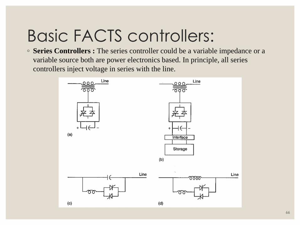
Basic FACTS controllers: ◦ Series Controllers : The series controller could be a variable impedance or a
variable source both are power electronics based. In principle, all series
controllers inject voltage in series with the line.
66
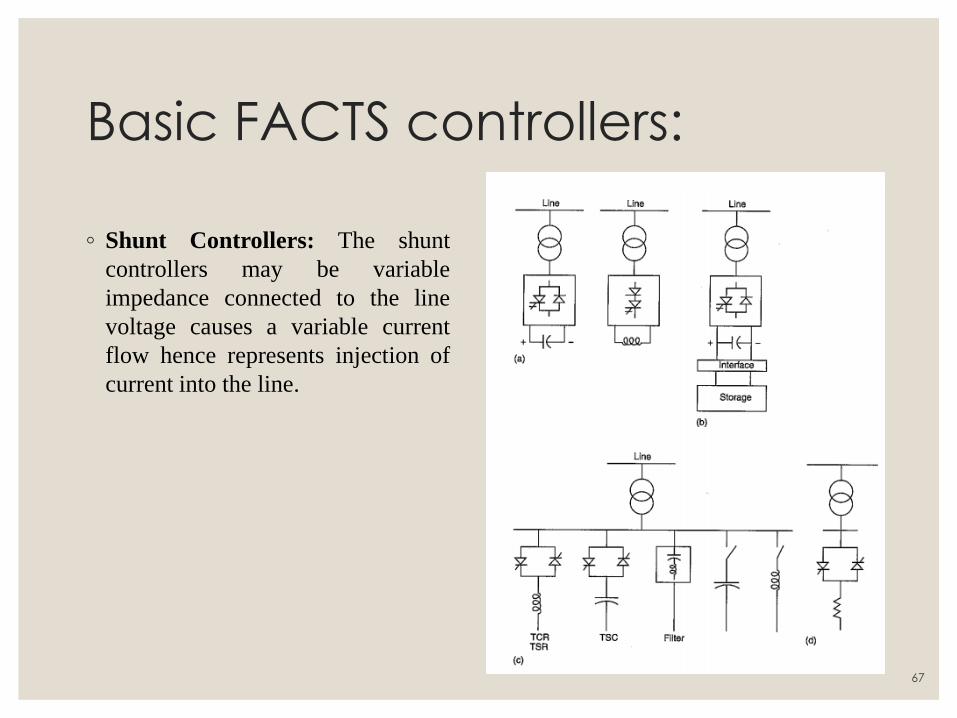
Basic FACTS controllers:
◦ Shunt Controllers: The shunt
controllers may be variable
impedance connected to the line
voltage causes a variable current
flow hence represents injection of
current into the line.
67
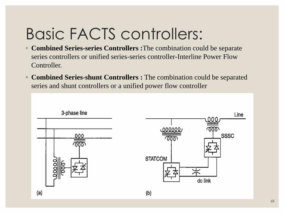
Basic FACTS controllers: ◦ Combined Series-series Controllers :The combination could be separate
series controllers or unified series-series controller-Interline Power Flow
Controller.
◦ Combined Series-shunt Controllers : The combination could be separated
series and shunt controllers or a unified power flow controller
68
69
CLASSIFICATION OF FACTS
The FACTS device can be classified in TWO ways.
◦ Depending on the type of connection to the network
◦ Serial controller
◦ Derivation controller
◦ Serial to serial controller
◦ Serial derivation controllers
◦ Depending on technological features the FACTS devices can be divided
into two generations:
◦ First generation - uses thyristors with ignition controlled by door (SCR).
◦ Second generation - semiconductors with ignition and extinction
controlled by door (GTO, IGBT, etc.).
70
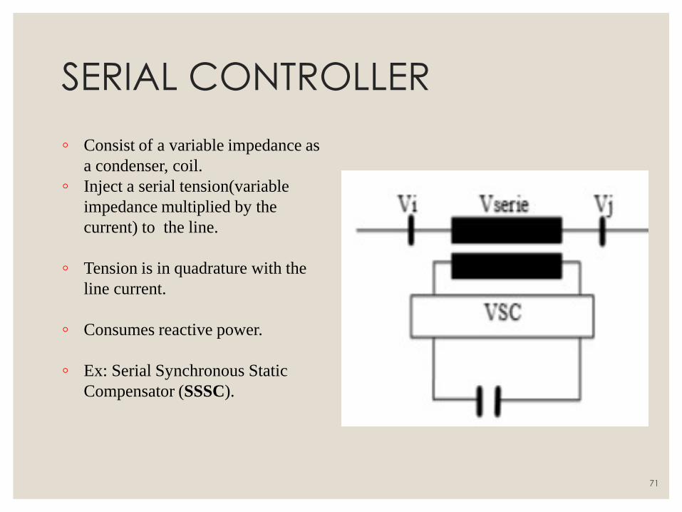
SERIAL CONTROLLER
◦ Consist of a variable impedance as
a condenser, coil.
◦ Inject a serial tension(variable
impedance multiplied by the
current) to the line.
◦ Tension is in quadrature with the
line current.
◦ Consumes reactive power.
◦ Ex: Serial Synchronous Static
Compensator (SSSC).
71
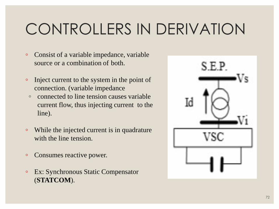
CONTROLLERS IN DERIVATION
◦ Consist of a variable impedance, variable
source or a combination of both.
◦ Inject current to the system in the point of
connection. (variable impedance
◦ connected to line tension causes variable
current flow, thus injecting current to the
line).
◦ While the injected current is in quadrature
with the line tension.
◦ Consumes reactive power.
◦ Ex: Synchronous Static Compensator
(STATCOM).
72
SERIAL – SERIAL CONTROLLERS
◦ Combination of coordinated serial controllers in a multiline
transmission system or can also be an unified controller.
◦ The serial controllers provide serial reactive compensation for each
line also transferring active power between lines through the link of
power.
◦ The term “unified” means that the DC terminals of the converters of
all the controllers are connected to achieve a transfer of active power
between each other.
◦ Ex: Interline Power Flow Compensator (IPFC).
73
SERIAL DERIVATION CONTROLLERS
◦ Combination of serial and derivations controllers separated, co-
ordinately controlled.
◦ Inject current to the system through the component in derivation of the
controller, and serial tension with the line utilizing the serial
component.
◦ When the serial and derivation controllers are unified, they can have an
exchange of active power between them through their link.
◦ Ex: Unified Power Flow Controller (UPFC)
74
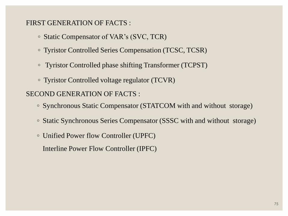
FIRST GENERATION OF FACTS :
◦ Static Compensator of VAR’s (SVC, TCR)
◦ Tyristor Controlled Series Compensation (TCSC, TCSR)
◦ Tyristor Controlled phase shifting Transformer (TCPST)
◦ Tyristor Controlled voltage regulator (TCVR)
SECOND GENERATION OF FACTS :
◦ Synchronous Static Compensator (STATCOM with and without storage)
◦ Static Synchronous Series Compensator (SSSC with and without storage)
◦ Unified Power flow Controller (UPFC)
Interline Power Flow Controller (IPFC)
75
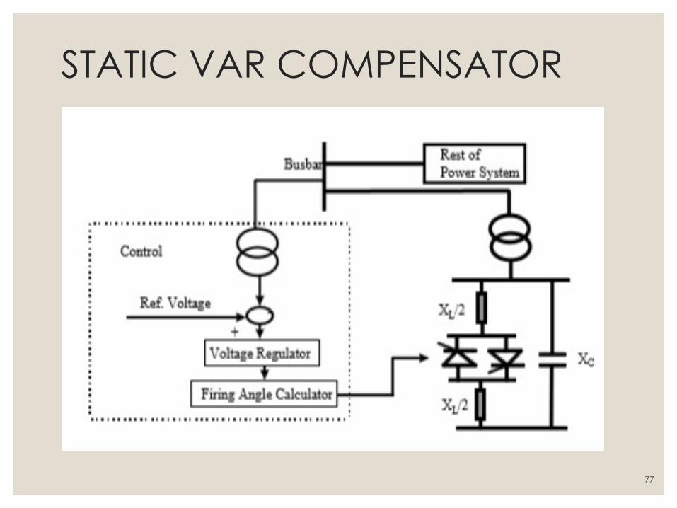
STATIC VAR COMPENSATOR
◦ Regulate voltage and stabilise(dynamic) the system.
◦ SVC is an automated impedance matching device, designed to bring the
system closer to unity power factor.
◦ If load is capacitive (leading), the SVC will use reactors (in form of CR)
◦ Under inductive (lagging) ,the capacitor banks are automatically switched in.
◦ SVR may be placed near high and rapidly varying loads, such as arc
furnaces, where they can smooth flicker voltage.
76
STATIC VAR COMPENSATOR
77
STATIC SYNCHRONOUS COMPENSATOR
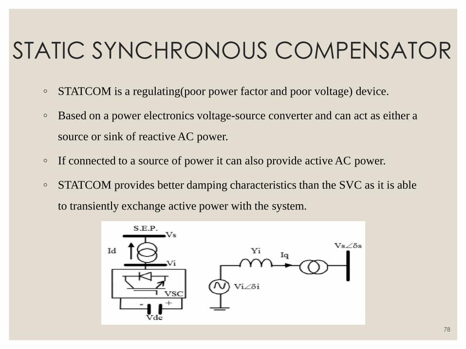
◦ STATCOM is a regulating(poor power factor and poor voltage) device.
◦ Based on a power electronics voltage-source converter and can act as either a
source or sink of reactive AC power.
◦ If connected to a source of power it can also provide active AC power.
◦ STATCOM provides better damping characteristics than the SVC as it is able
to transiently exchange active power with the system.
78
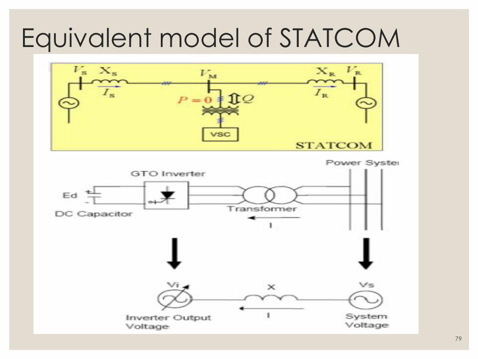
Equivalent model of STATCOM
79
UNIT V COMPENSATORS
80
SERIES COMPENSATION:
◦ The main purpose of series compensation in power systems is to decrease the
reactive impedance of the transmission line to reduce voltage drop over long
distances and to reduce the Ferranti effect. By adding series capacitors to the
line, engineers can compensate for the physical inductance inherent in the
transmission line. The voltage drop across the line is reduced with more
compensation, allowing more power to be received by the load for any given
sending power. Two main types of series compensation are fixed series
compensation, and thyristor controlled series compensation, each with their
own advantages.
81
FIXED SERIES COMPENSATION: ◦ Fixed series compensation (FSC) of a line is desirable for power transmission
due to the effects of line reactance modification. By adding series capacitance,
the reactive impedance of the line decreases, thus lowering the voltage drop
across the transmission line. This effect can be seen through the simplified
power flow equation (see the post about Power Transfer) obtained by
neglecting line resistance and line charging capacitance.
◦ Line reactance is counteracted by a series capacitance, resulting in overall
lower line impedance and a lower voltage drop across the line.
◦ By adding the series capacitance, it can be seen that the receiving line end
voltage will be closer to the sending line end voltage. This decrease in voltage
drop across the line allows more power to be transferred over the line for any
given sending line end voltage.
82
METHODS OF CONTROLLABLE VAR GENERATION ◦ VARIABLE IMPEDANCE TYPE STATIC VAR GENERATORS:
◦ GTO THYRISTOR-CONTROLLED SERIES CAPACITOR (GCSC)
◦ THYRISTOR-CONTROLLED SERIES CAPACITOR (TCSC)
◦ THYRISTOR-SWITCHED SERIES CAPACITOR (TSSC)
◦ SWITCHING CONVERTER TYPE VAR GENERATORS
◦ STATIC SYNCHRONOUS SERIES COMPENSATOR (SSSC)
83
Basic operation of GSSC, TCSC, TSSC ◦ Structurally the internal controls for the three variable impedance type
compensators (GCSC, TCSC, TSSC) could be similar. Succinctly, their function is simply to define the conduction and/or the blocking intervals of the valve in relation to the fundamental (power frequency) component of the line current. This requires the execution of three basic functions:
◦ synchronization to the line current,
◦ turn-on or turn-off delay angle computation, and
◦ gate (firing) signal generation.
◦ These functions obviously can be implemented by different circuit approaches, with differing advantages and disadvantages. In the following, three possible internal control schemes are functionally discussed: one for the GCSC, and the other two for the TCSC power circuit arrangements. Either of the TCSC schemes could be adapted for the TSSC if sub synchronous resonance would be an application concern.
84
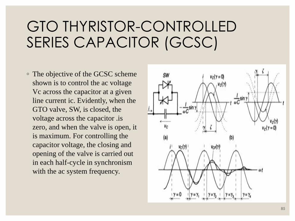
GTO THYRISTOR-CONTROLLED SERIES CAPACITOR (GCSC) ◦ The objective of the GCSC scheme
shown is to control the ac voltage
Vc across the capacitor at a given
line current ic. Evidently, when the
GTO valve, SW, is closed, the
voltage across the capacitor .is
zero, and when the valve is open, it
is maximum. For controlling the
capacitor voltage, the closing and
opening of the valve is carried out
in each half-cycle in synchronism
with the ac system frequency.
85
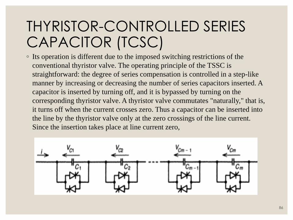
THYRISTOR-CONTROLLED SERIES CAPACITOR (TCSC) ◦ Its operation is different due to the imposed switching restrictions of the
conventional thyristor valve. The operating principle of the TSSC is
straightforward: the degree of series compensation is controlled in a step-like
manner by increasing or decreasing the number of series capacitors inserted. A
capacitor is inserted by turning off, and it is bypassed by turning on the
corresponding thyristor valve. A thyristor valve commutates "naturally," that is,
it turns off when the current crosses zero. Thus a capacitor can be inserted into
the line by the thyristor valve only at the zero crossings of the line current.
Since the insertion takes place at line current zero,
86
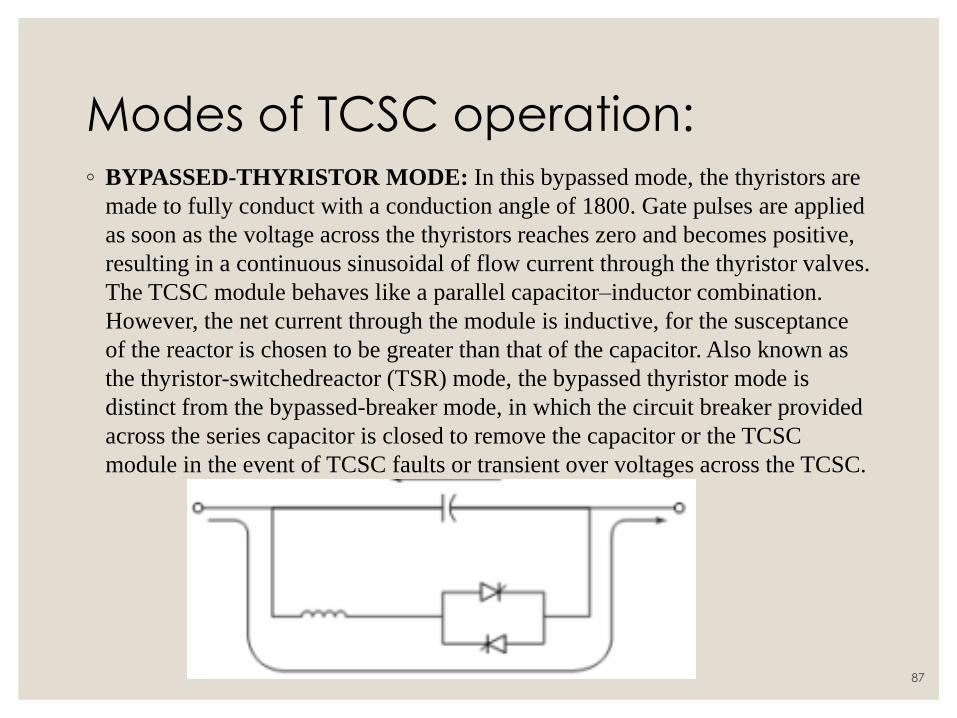
Modes of TCSC operation: ◦ BYPASSED-THYRISTOR MODE: In this bypassed mode, the thyristors are
made to fully conduct with a conduction angle of 1800. Gate pulses are applied
as soon as the voltage across the thyristors reaches zero and becomes positive,
resulting in a continuous sinusoidal of flow current through the thyristor valves.
The TCSC module behaves like a parallel capacitor–inductor combination.
However, the net current through the module is inductive, for the susceptance
of the reactor is chosen to be greater than that of the capacitor. Also known as
the thyristor-switchedreactor (TSR) mode, the bypassed thyristor mode is
distinct from the bypassed-breaker mode, in which the circuit breaker provided
across the series capacitor is closed to remove the capacitor or the TCSC
module in the event of TCSC faults or transient over voltages across the TCSC.
87
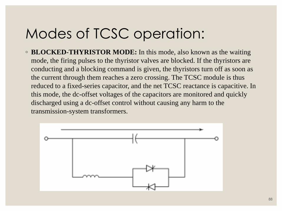
Modes of TCSC operation: ◦ BLOCKED-THYRISTOR MODE: In this mode, also known as the waiting
mode, the firing pulses to the thyristor valves are blocked. If the thyristors are
conducting and a blocking command is given, the thyristors turn off as soon as
the current through them reaches a zero crossing. The TCSC module is thus
reduced to a fixed-series capacitor, and the net TCSC reactance is capacitive. In
this mode, the dc-offset voltages of the capacitors are monitored and quickly
discharged using a dc-offset control without causing any harm to the
transmission-system transformers.
88
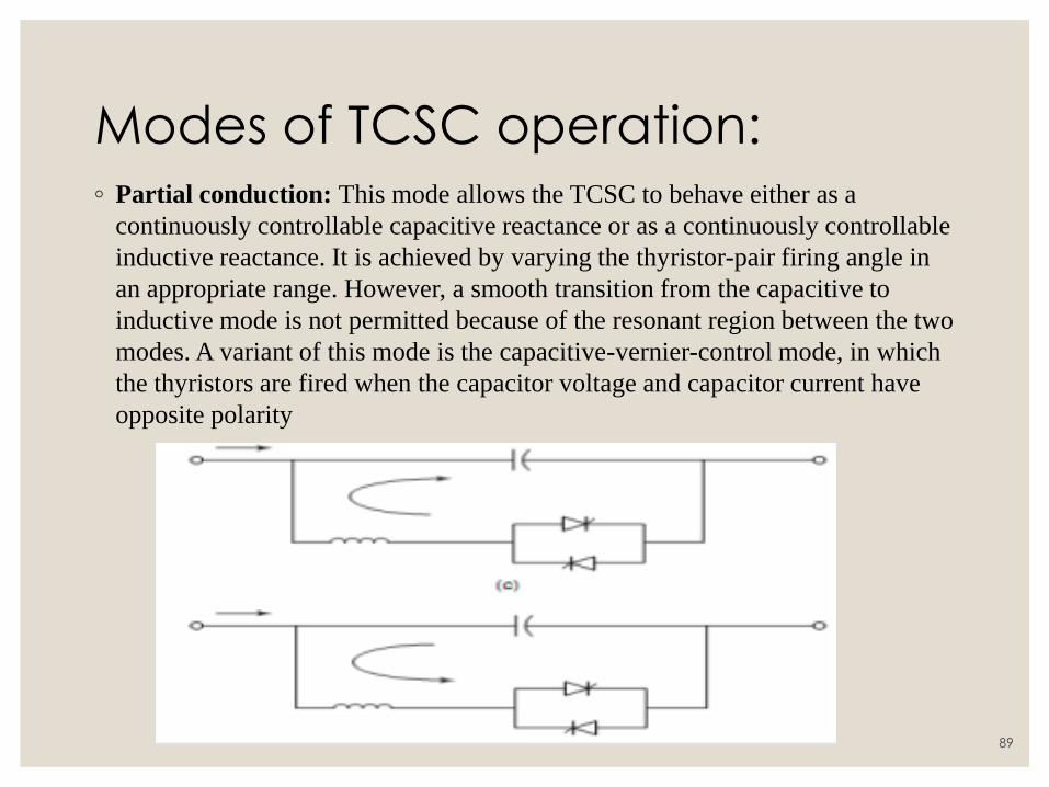
Modes of TCSC operation: ◦ Partial conduction: This mode allows the TCSC to behave either as a
continuously controllable capacitive reactance or as a continuously controllable
inductive reactance. It is achieved by varying the thyristor-pair firing angle in
an appropriate range. However, a smooth transition from the capacitive to
inductive mode is not permitted because of the resonant region between the two
modes. A variant of this mode is the capacitive-vernier-control mode, in which
the thyristors are fired when the capacitor voltage and capacitor current have
opposite polarity
89
Advantages of TCSC ◦ Use of thyristor control in series capacitors potentially offers the following
little-mentioned advantages:
◦ Rapid, continuous control of the transmission-line series-compensation level.
◦ Dynamic control of power flow in selected transmission lines within the
network to enable optimal power-flow conditions and prevent the loop flow of
power.
◦ Damping of the power swings from local and inter-area oscillations.
◦ Suppression of subsynchronous oscillations. At subsynchronous frequencies,
the TCSC presents an inherently resistive–inductive reactance. The
subsynchronous oscillations cannot be sustained in this situation and
consequently get damped.
◦ Decreasing dc-offset voltages. The dc-offset voltages, invariably resulting
from the insertion of series capacitors, can be made to decay very quickly
(within a few cycles) from the firing control of the TCSC thyristors.
◦ Enhanced level of protection for series capacitors. A fast bypass of the series
capacitors can be achieved through thyristor control when large over voltages
develop across capacitors following faults. Likewise, the capacitors can be
quickly reinserted by thyristor action after fault clearing to aid in system
stabilization
90
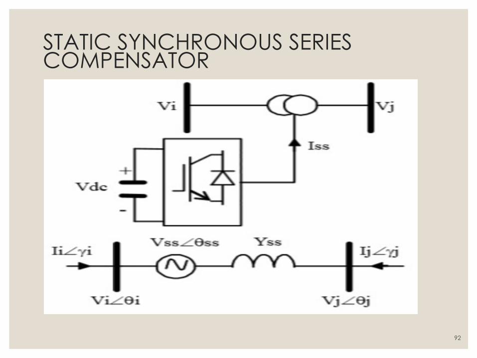
STATIC SYNCHRONOUS SERIES COMPENSATOR ◦ Works the same way as the STATCOM.
◦ It has a VSC serially connected to a transmission line through a
transformer.
◦ A SSSC is able to exchange active and reactive power with the
transmission system.
◦ Thus SSSC can work like a controllable serial condenser and serial reactor.
◦ The voltage injected through a SSSC is not related to the line intensity and
can be controlled independently.
◦ As a result SSSC can give good results with low loads as well as high
loads.
91
STATIC SYNCHRONOUS SERIES COMPENSATOR
92
UNIFIED POWE FLOW CONTROL
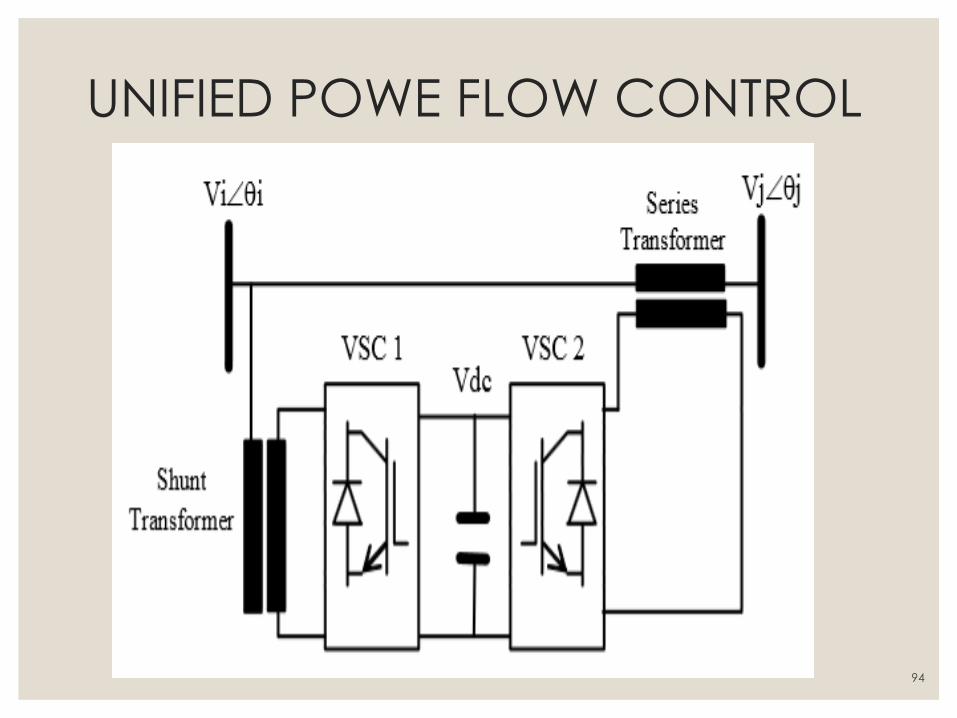
◦ A UPFC system can regulate the active and reactive power at same time.
◦ It has the ability to adjust the three control parameters(bus voltage,
transmission line reactance, and phase angle between two buses, either
simultaneously or independently).
◦ The converter 2 has the main function of the UPFC; it injects an AC voltage
to the line, where magnitude and phase angle are controllable through a
serial transformer.
◦ Converter 1 give or absorb the real power that the converter 2 demands.
93
UNIFIED POWE FLOW CONTROL
94
Reactive power control: ◦ In high voltage direct current (HVDC) converters, the stations are line
commutated. This implies that the initial current of the valve can only be
delayed in reference a zero value of the converter bus voltage in AC form.
Consequently, for better control of voltage, the converter bus is connected to a
reactive power source.
◦ Reactive power sources are used to vary capacitors in static systems. The
response of the reactive power system is dictated by voltage control in dynamic
conditions.
◦ When operating unstable AC systems, problems tend to arise because of
unstable voltage and overvoltage surges. A better coordination of reactive
power sources is required to simplify the control of the firing angles. As a
result, this feature of the reactive power converter is increasingly being applied
in modern converters using HVDC.
95
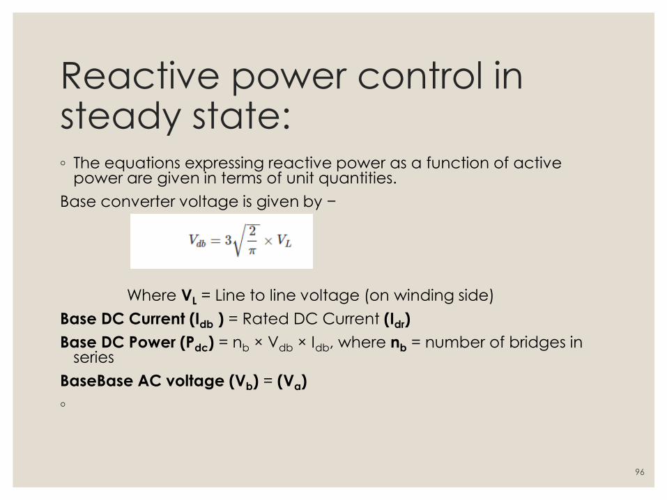
Reactive power control in steady state: ◦ The equations expressing reactive power as a function of active
power are given in terms of unit quantities.
Base converter voltage is given by −
Where VL = Line to line voltage (on winding side)
Base DC Current (Idb ) = Rated DC Current (Idr)
Base DC Power (Pdc) = nb × Vdb × Idb, where nb = number of bridges in series
BaseBase AC voltage (Vb) = (Va)
◦
96
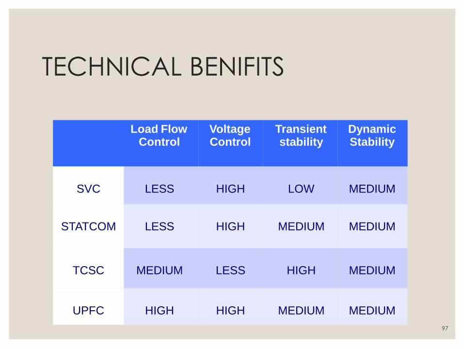
TECHNICAL BENIFITS
Load Flow Control
Voltage Control
Transient stability
Dynamic Stability
SVC
LESS
HIGH
LOW
MEDIUM
STATCOM
LESS
HIGH
MEDIUM
MEDIUM
TCSC
MEDIUM
LESS
HIGH
MEDIUM
UPFC
HIGH
HIGH
MEDIUM
MEDIUM
97
MAINTANANCE OF FACTS
◦ Is minimal and similar to that required for shunt capacitors, reactors and
transformers
◦ The amount of maintenance ranges from 150 to 250 man-hours per year
Operation of FACTS devices
◦ operated automatically
◦ can be done locally and remotely
98
APPLICATION OF FACTS
◦ Steady state voltage stability
◦ Power flow control
◦ Damping of power system oscillations
◦ Reducing generation costs
◦ HVDC link application
◦ Deregulated power systems
◦ Flicker mitigation
◦ Interconnection of renewable, distributed generation and storages.
99
FUTURE ENHANCMENTS OF FACTS ◦ Several FACTS devices have been introduced for various application world-
wide.
◦ A number of new types of devices are in the stage of being introduced in
practice.
◦ Many new devices are under research process, such as HFC (Hybrid
Flow Controller)
◦ RHFC (Rotary Hybrid Flow Controller) DPFC (distributed
power flow controller)
◦ C-UPFC (center node) and many more…….
100

Thank you….
101


![Power hardware in the loop validation of fault ride ... · advantages over the HVAC transmission system [3–6]. The choice between a HVAC and a HVDC transmission system depends upon](https://img.pdfslide.us/doc/110x75/5ebf935af4163c04dc17b09f/power-hardware-in-the-loop-validation-of-fault-ride-advantages-over-the-hvac.jpg)