Embed Size (px)
Citation preview

General Overview of HVDC Transmission System

WHY HVDC ?
Asynchronous connection (enables to connect two different electrical networks having different frequency & voltage)
Power flow control (enables the stability of electrical network)
Added benefit to the transmission like stability, power quality etc.
WHY HVDC?
Environmental advantages (lesser right of way requirement)
Lower line losses compared to AC line (no corona & charging current)
Economical (only two conductor for transmission & lesser tower height)

Comparison With HVAC
ITEM HVAC HVDC 1. Power Transmission Capability Low High (e.g. 3000 MW
Bipole) 2. Distance Limited by Stability
considerations. Switching Stations required.
No Limitation. Cheaper alternative for Long Distances
3. System Connection Synchronous Asynchronous
4. Right of Way requirements High Low 5. Power Control No Yes 6. Features – Frequency Control,
Reactive Power Control, Damping of Oscillations etc.
Not Available Available

Comparison With HVAC
ITEM HVAC HVDC 7. Tapping of Power Connection Simple Costly, Multi-terminal
Scheme required 8. Economical Alternative for Low to Medium distance,
Medium Power Range. Long Distance Bulk Power Transmission
9. System SCL (for consideration in developed AC systems due to high fault currents)
Contributes to System SCL
Does not Contribute to System SCL
10.
Pollution Effects Relatively Lesser More Pronounced Higher insulator creepage distance is required

SO WHY HVDC RATHER THAN HVAC ?
Long distances make HVDC cheaper
Improved link stability
Fault isolation
Asynchronous link
Control of load flow (DC voltage can be exactly controlled)

96 m 46 m
400 kV AC Lines 500 kV DC Line
Comparison of right of way

Cost comparison of ac and dc transmission
Cost of DC terminal
Cost of AC terminal
CostBreak even distance
Distance in km
Cost of AC Line
Cost of DC Line
500 – 700 km

Types of HVDC Transmission system
Mono Polar System:
One pole, one conductor for transmission and current return path is through earth.
Mainly used for submarine cable transmission.

Types of HVDC Transmission system
Bipolar System:
Two poles, two conductors in transmission line, one positive with respect to earth & other negative
The mid point of Bi-poles in each terminal is earthed via an electrode line and earth electrode.
In normal condition power flows through lines & negligible current through earth electrode. (in order of less than 10 Amps.)

Types of HVDC Transmission system
Homo Polar System:
Two poles at same polarity & current return path is through ground.
This system was used earlier for combination of cable & over head transmission.

Types of HVDC Transmission system
Back to Back HVDC Coupling: Usually bipolar without earth return. Converter & inverters are located at the same place. No HVDC Transmission line. Provides Asynchronous tie between two electrical
network Improves system stability Power transfer can be in either direction.

Types of HVDC Transmission system
Multi Terminal HVDC System:
Three or more terminal connected in parallel, some feed power and some receive power from HVDC Bus.
Provides Inter connection between the three or more AC network.
System stability of AC network can be improved.

HOW HVDC WORKS

POWER FLOW EQUATIONS
FOR AC TRANSMISSION:
POWER(P) = V1 V2
XSinδ

POWER FLOW EQUATIONS
FOR DC TRANSMISSION:
POWER(P) = Vdr (Vdr-Vdi)
R

HVDC Transmission Normal Power Direction
Rectifier Inverter
Note! Only a small voltage difference
Id
Page 28

RectifierInverter
Note that the current flow is in the same direction.Only the polarity is reversed.(changing a).
Id
HVDC Transmission Reverse Power Direction
Note! Only a small voltage difference
Page 29
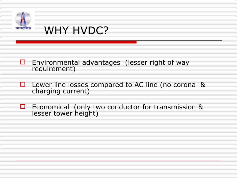
Basic Diagram of HVDC System
DCTRANSMISSION
LINE
Pd = Vd Id
FILTER
Vd
AC SYSTEM A TERMINAL A
Ld Id
FILTER
TERMINAL B
Ld
AC SYSTEM B

6-Pulse Convertor Bridge
3
6
CiLs
4
E1 Ls
Ls
Bi
iA
1
2
I
V'd
5
Vd
IddL
d

12-Pulse Convertor Bridge
Y

Filter
12-Pulse Valve Group With AC Filters

BIPOLE HVDC
MODES OF OPERATION

BASIC HVDC Single Line Diagram
DC OH Line
Converter Transformer
DC Filter:DT 12/24DT 12/36
DC Filter:DT 12/24DT 12/36
ThyristorValves
400 kV AC Bus
AC Filters
Smoothing Reactor
Converter Transformer
DC Filter:DT 12/24DT 12/36
DC Filter:DT 12/24DT 12/36
ThyristorValves
400 kV AC Bus
AC Filters
Smoothing Reactor

Modes of Operation
DC OH Line
Converter Transformer
ThyristorValves
400 kV AC Bus
AC Filters,Reactors
Smoothing Reactor
Converter Transformer
ThyristorValves
400 kV AC Bus
AC Filters
Smoothing Reactor
Bipolar
Current
Current

Modes of Operation
DC OH Line
Converter Transformer
ThyristorValves
400 kV AC Bus
AC Filters,Reactors
Smoothing Reactor
Converter Transformer
ThyristorValves
400 kV AC Bus
AC Filters
Smoothing Reactor
Monopolar Ground Return
Current

Modes of Operation
DC OH Line
Converter Transformer
ThyristorValves
400 kV AC Bus
AC Filters,Reactors
Smoothing Reactor
Converter Transformer
ThyristorValves
400 kV AC Bus
AC Filters
Smoothing Reactor
Monopolar Metallic Return
Current

HVDC Thyristor Valves
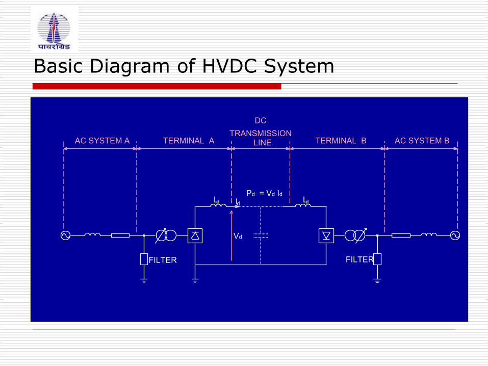
Modern Thyristor Valves
Valve Modular Design
Suspended Installation
Water Cooled


Valve Hall Equipments & Thyristors at Vindhyachal
THYRISTOR VALVE:
AIR INSULATED
WATER COOLED
DESIGNED FOR INDOOR USE
OCTUPLE UNIT (Each Physical Structure Contain 08 Valve Functions)

Each single valve has 04 Thyristor modules connected in series
Each Thyristor Module has 06 thyristors with Voltage Divider & Control circuits
Each Thyristor Module in a Valve is series connected to a Reactor
Total no of Thyristors in one valve hall : 576
Each valve has 1 Thyristor redundant out of 24
Valve Hall Equipments & Thyristors at Vindhyachal
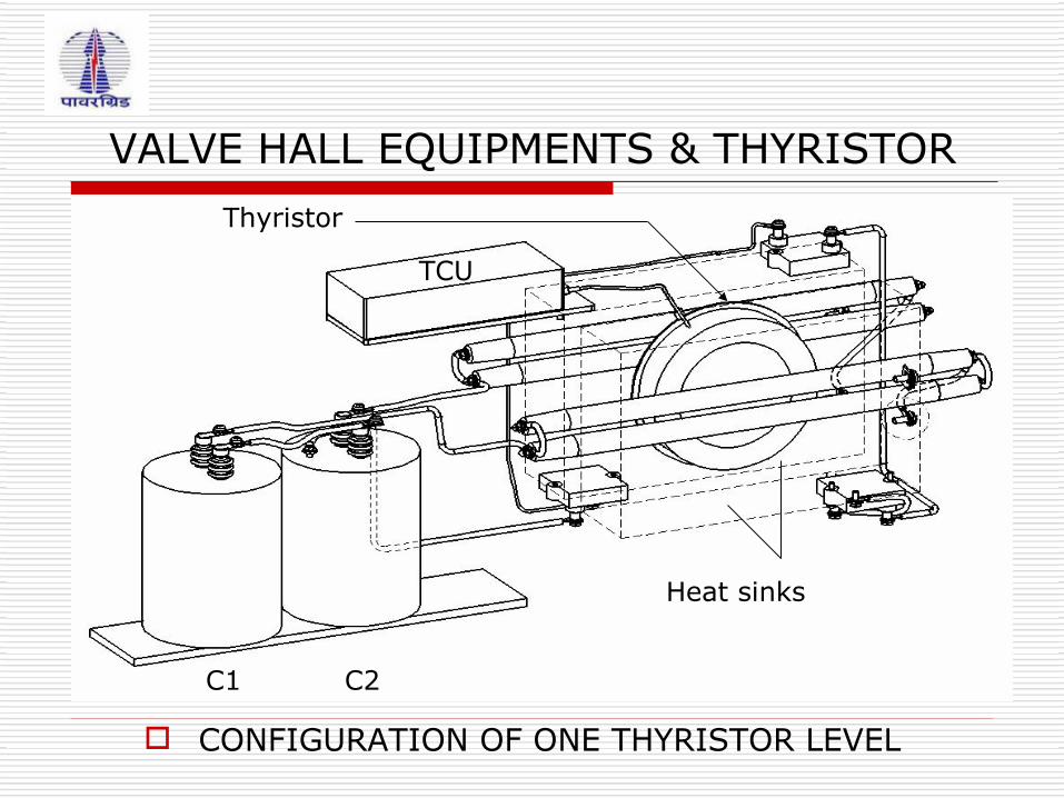
VALVE HALL EQUIPMENTS & THYRISTOR
CONFIGURATION OF ONE THYRISTOR LEVEL
Thyristor
TCU
C1 C2
Heat sinks

HVDC Vindhyachal Thyristor Rating
CURRENT RATING: RATED DIRECT CURRENT: 3600 A MAX. DIRECT CURRENT AT RATED POWER: 3700 A MAX. DIRECT CURRENT AT OVERLOAD: (i) Id MAX FOR 2HR IN 12 HRS. : 4150 A (ii) Id MAX FOR 5 SEC. IN 5 MIN. : 4650 A
VOLTAGE RATING: NON REPETITIVE REVERSE VOLTAGE: 5350 V NON REPETITIVE FORWARD VOLTAGE: 4850 V

Valve Reactor

Thyristor

Thyristors
The Thyristor is a solid state semiconductor switching device with four layers of alternating P and N type material.
It has three terminals; Anode, Cathode & Gate
The Thyristor continue to conduct as long as they are forward biased ( that is as long as the voltage across the device has not reversed).
N
P
P
N
Anode
Cathode
Gate
J1
J2
J3
Thyristor vs Diode
Like the Diode, Thyristor is also unidirectional device that blocks current flow from cathode to anode.
Unlike the Diode, a Thyristor also blocks current flow from anode to cathode until it is triggered by a proper gate signal between gate & cathode terminals.

Static I-V Characteristics of a Thyristor
V bo +Va
+Ia
-Va
-Ia
Vbo = Forward break over voltage
Forward blocking mode
Forward conduction mode
Reverse blocking mode
Latching current
Holding current
Vbr = Reverse breakdown voltage
Vbr
Forward leakage current
Reverse leakage current

Effect of Gate Current on Forward Breakover Voltage
The effect of gate current on the forward break over voltage of thyristor can be understood by the figure alongside.
For Ig = 0, forward break over voltage is Vbo
For Ig1>Ig, forward break over voltage is V1<Vbo
For Ig2>Ig1, forward break over voltage is V2<V1<Vbo
For Ig3>Ig2>Ig1, forward break over voltage is V3<V2<V1<Vbo
+Ia+Ia
+Va+Va
Ig=0Ig=0
Ig1Ig1 Ig2Ig2Ig3Ig3
Ig3>Ig2>Ig1Ig3>Ig2>Ig1
V1V1 V2V2V3V3
V3<V2<V1V3<V2<V1
VboVbo
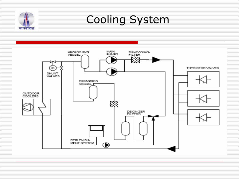
Cooling System

Basic Control Concepts
DC Line
α γ
Current Reference Voltage Reference
InverterRectifier

Powercontrol
Iorder Currentcontrol
amplifier
Converterunitfiring
control Id
Iresponse
Voltagemeasuring
system
Porder
Pmod
Ud response
To inverter
HVDC control system

Basic Control Concepts
1.0
1.0
Ud (p.u.)
Id (p.u.)
Rect Id Cont
Oper. Point
Inverter Characteristics
Rectifier Characteristics
Converter Characteristics Converter Characteristics

Basic Control Concepts
Converter Characteristics Converter Characteristics
1.0
1.0
Ud (p.u.)
Id (p.u.)
Rect Id Cont
Oper. Point
Inv Id Cont
Inverter Characteristics
Rectifier Characteristics

YY
Y
iy
i
iy i+
%
5 7 11 13 17 19 23 25
11 13 23 25
510
510
iy
in
iy + i in
iy
i
iy i+
AC Side Harmonics

Transformer function in HVDC system
•Supply of AC voltages into two separate circuits feeding the rectifier bridges with a phase shift of 30 electrical degrees for reduction of low order harmonics esp. 5th & 7th harmonics. •As a galvanic barrier between AC and DC systems to prevent DC potential entering into the AC system •Reactive Impedance in the AC supply to reduce short circuit currents and to control the rate of rise in valve current during commutation.

Converter Transformers
Type of Connections No. of design X No. of units
Spares required
3 Phase Star-Delta & Star-Star
2 X 2 2
Single phase 2 winding 2 X 6 2
Singe phase 3 winding 2 x 3 1
Extended delta-connection
2 X 2 1
3 Phase 3 winding 2 X 2 1

DC High Speed Switches Transfer between configurations
Transfer between configurations by means of MRTB and MRS(GRTS)

DC MEASURING DEVICESDC MEASURING DEVICES
Measurement on DC side for control, monitoring and Protection AC CTs cannot be used on DC side – saturation DC current measuring devices –
DC shunt – low value resistor mV drop from the shunt will be taken for determining the current To solve insulation problems – electrical signals are converted to optical at the
shunt and at control system converted to electrical Supply for the conversion process is obtained from the control panels in the form
of optical power DC voltage divider
Capacitive & resistor divider circuit Drop across the resistor scaled for determining the voltage Optical conversion process is same as the current measuring device

Smoothing Reactor -
Connected in series in each converter with each pole Decreases harmonic voltages and currents in the DC line Smoothen the ripple in the DC current and prevents the
current from becoming discontinuous at light loads Limits crest current (di/dt) in the rectifier due to a short
circuit on DC line Limits current in the bypass valve firing due to the
discharge of the shunt capacitances of the dc line

To reduce the magnitude of the harmonic currents circulating in the HVDC transmission line to avoid unacceptable interferences.
DC filters are needed for HVDC transmission with Bipole Link and overhead line.
In the case of back-to-back and cable transmission systems, there are no requirements for dc filters.
DC Filters

Thank You


![Power hardware in the loop validation of fault ride ... · advantages over the HVAC transmission system [3–6]. The choice between a HVAC and a HVDC transmission system depends upon](https://img.pdfslide.us/doc/110x75/5ebf935af4163c04dc17b09f/power-hardware-in-the-loop-validation-of-fault-ride-advantages-over-the-hvac.jpg)