Embed Size (px)
Citation preview

POWER PLANT ENGINEERINGCourse Code:A70353,JNTUH R-15
IV B-TECH, I-SEM
Prepared By
Mr. G. Sarat Raju, Assistant Professor.
Mrs. G. Karunya, Assistant Professor.
Mechanical Engineering.
INSTITUTE OF AERONAUTICAL ENGINEERING(Autonomous)
Dundigal, Hyderabad - 500 043
UNIT – I
INTRODUCTION TO THE
SOURCES OF ENERGY
2
Definition
A power station (also referred to as a generating station, power
plant, powerhouse or generating plant) is an industrial facility for
the generation of electric power.
3
Types of Power Plants
1.BASED ON INPUT ENERGY /FUEL
(a.)COAL thermal Power Plants
(b.) HYDRAULIC Power Plants
(c.) NUCLEAR Power Plants
(d.) GEOTHERMAL Power Plants
(e.) SOLAR Power Plants
(f.)WIND power plants
(g.)BIOMASS power plant
4
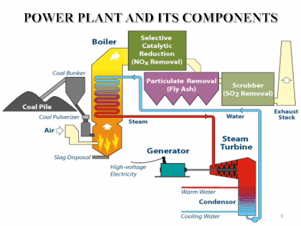
Coal Thermal Power Plant
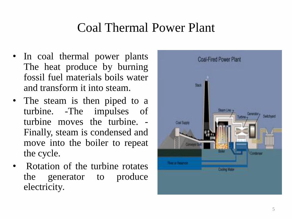
• In coal thermal power plantsThe heat produce by burningfossil fuel materials boils waterand transform it into steam.
• The steam is then piped to aturbine. -The impulses ofturbine moves the turbine. -Finally, steam is condensed andmove into the boiler to repeatthe cycle.
• Rotation of the turbine rotatesthe generator to produceelectricity.
5
6
MAIN PARTS OF THE PLANT ARE :-
• COAL HANDLING PLANT
• PRE TREATMENT and DM PLANT
• COOLING TOWER
• BOILER and its Components
• ASH HANDLING PLANT
• TURBINE GENERATOR
• TRANSFORMERS
• SWITCH YARD
COMPONENTS
7
CHP (Coal Handling
Plant)
8
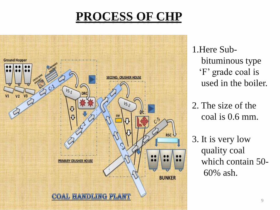
1.Here Sub-
bituminous type
„F‟ grade coal is
used in the boiler.
2. The size of the
coal is 0.6 mm.
3. It is very low
quality coal
which contain 50-
60% ash.
PROCESS OF CHP
9
1. CRUSHER
2. VIBRATING SCREEN
3. CONVEYER
4. MAGNETIC SEPARATOR
5. VIBRO FEEDER
MAIN EQUIPMENT IN CHP
10
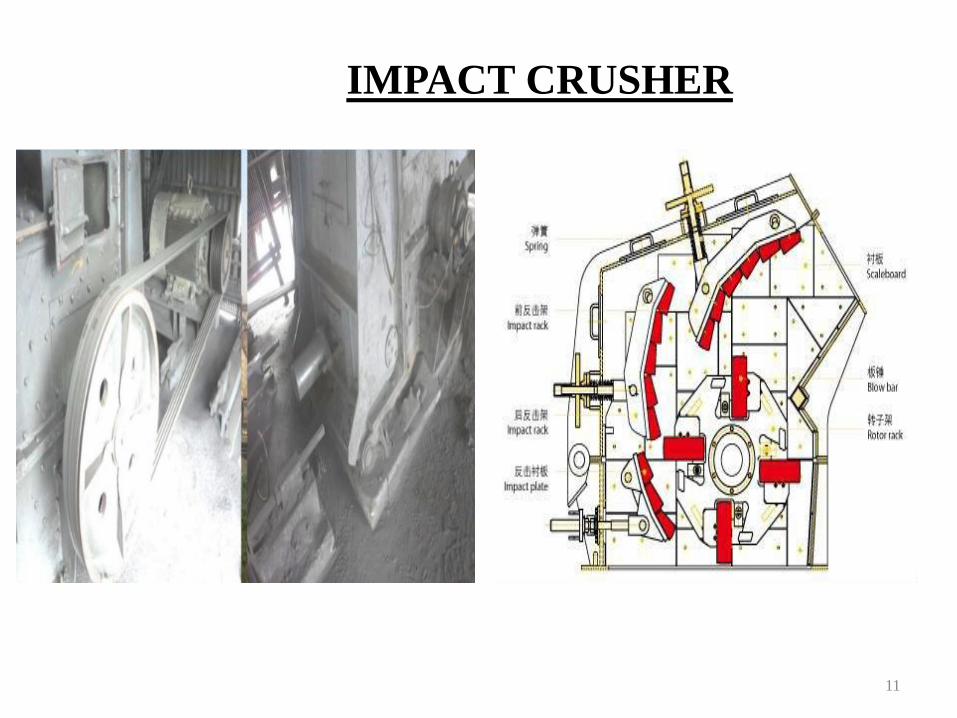
IMPACT CRUSHER
11
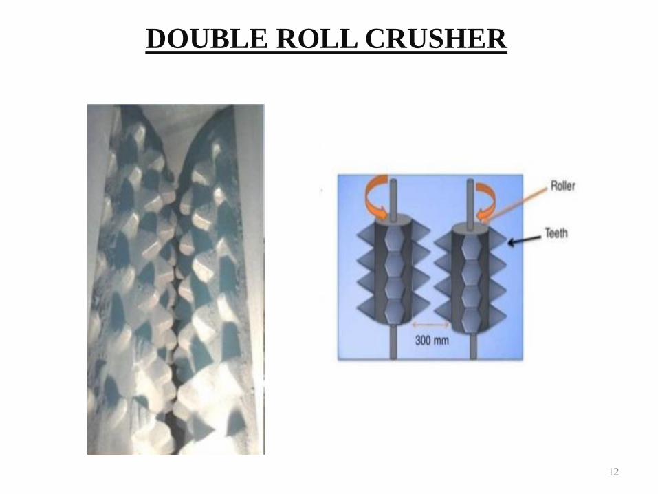
DOUBLE ROLL CRUSHER
12

VIBRATING SCREEN
13
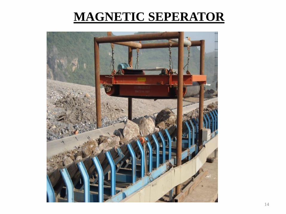
MAGNETIC SEPERATOR
14

VIBRO FEEDER
15

RESERVOIR (Mahanadi, Kelo)
STEALING CHAMBER (Cl2 dozing)
PARSELL FLUME (5% Polly Aluminium Chloride dozing)
INNER CELL CLEARIFIER (Removes sludges)
OUTER CELL CLEARIFIER
RGF (Rapid Gravity Filter)
FWS (Filtered Water Storage)
PROCESS OF PRE TREATMENT PLANT
16
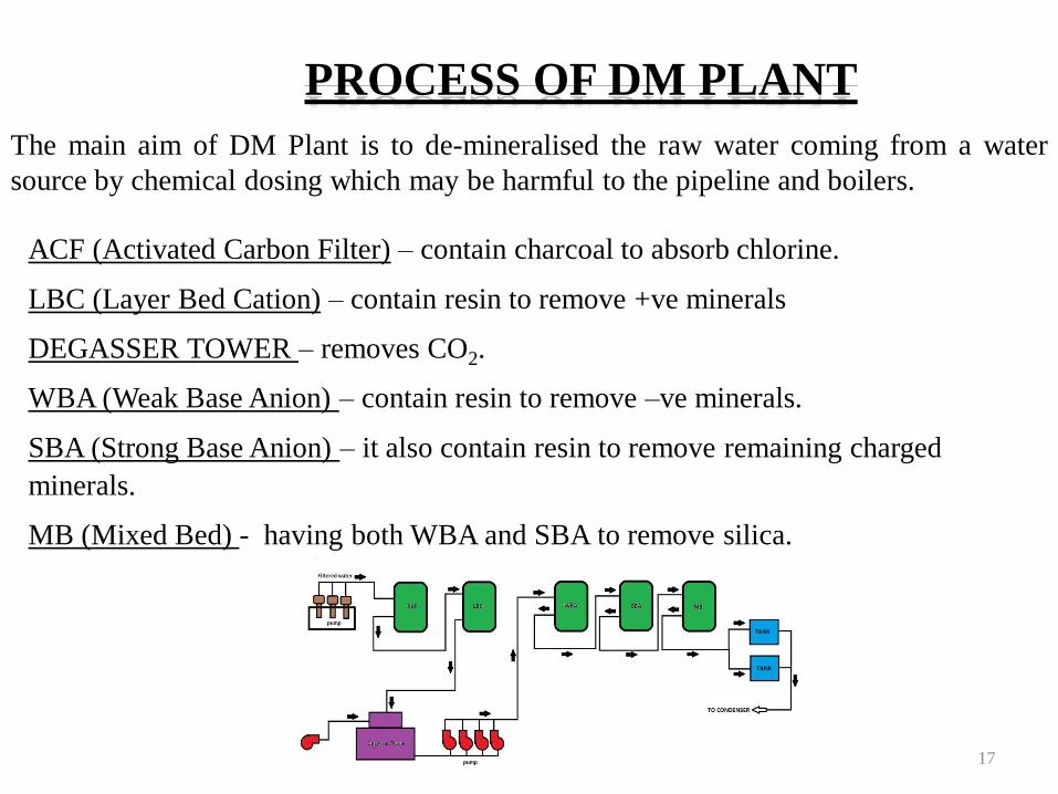
The main aim of DM Plant is to de-mineralised the raw water coming from a water
source by chemical dosing which may be harmful to the pipeline and boilers.
ACF (Activated Carbon Filter) – contain charcoal to absorb chlorine.
LBC (Layer Bed Cation) – contain resin to remove +ve minerals
DEGASSER TOWER – removes CO2.
WBA (Weak Base Anion) – contain resin to remove –ve minerals.
SBA (Strong Base Anion) – it also contain resin to remove remaining charged
minerals.
MB (Mixed Bed) - having both WBA and SBA to remove silica.
PROCESS OF DM PLANT
17
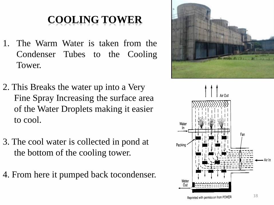
1. The Warm Water is taken from the
Condenser Tubes to the Cooling
Tower.
2. This Breaks the water up into a Very
Fine Spray Increasing the surface area
of the Water Droplets making it easier
to cool.
3. The cool water is collected in pond at
the bottom of the cooling tower.
4. From here it pumped back tocondenser.
18
COOLING TOWER
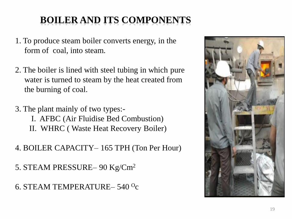
1. To produce steam boiler converts energy, in the
form of coal, into steam.
2. The boiler is lined with steel tubing in which pure
water is turned to steam by the heat created from
the burning of coal.
3. The plant mainly of two types:-
I. AFBC (Air Fluidise Bed Combustion)
II. WHRC ( Waste Heat Recovery Boiler)
4. BOILER CAPACITY– 165 TPH (Ton Per Hour)
5. STEAM PRESSURE– 90 Kg/Cm2
6. STEAM TEMPERATURE– 540 Oc
19
BOILER AND ITS COMPONENTS
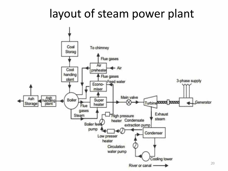
layout of steam power plant
20
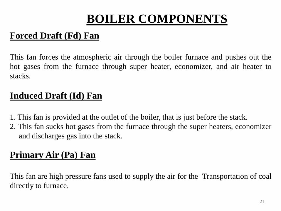
BOILER COMPONENTS
Forced Draft (Fd) Fan
This fan forces the atmospheric air through the boiler furnace and pushes out the
hot gases from the furnace through super heater, economizer, and air heater to
stacks.
Induced Draft (Id) Fan
1. This fan is provided at the outlet of the boiler, that is just before the stack.
2. This fan sucks hot gases from the furnace through the super heaters, economizer
and discharges gas into the stack.
Primary Air (Pa) Fan
This fan are high pressure fans used to supply the air for the Transportation of coal
directly to furnace.
21
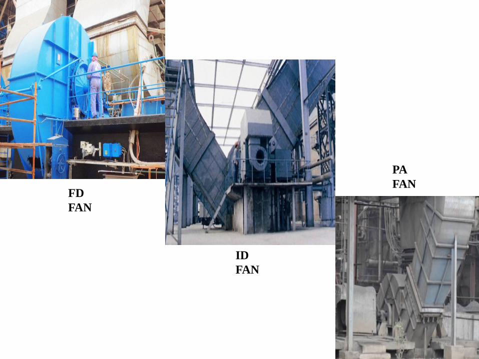
FD
FAN
ID
FAN
PA
FAN
22
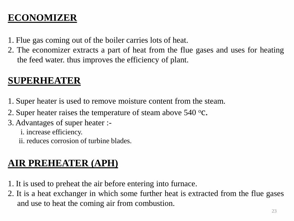
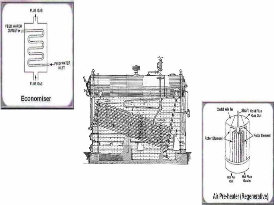
ECONOMIZER
1. Flue gas coming out of the boiler carries lots of heat.
2. The economizer extracts a part of heat from the flue gases and uses for heating
the feed water. thus improves the efficiency of plant.
SUPERHEATER
1. Super heater is used to remove moisture content from the steam.
2. Super heater raises the temperature of steam above 540 oc.3. Advantages of super heater :-
i. increase efficiency.
ii. reduces corrosion of turbine blades.
AIR PREHEATER (APH)
1. It is used to preheat the air before entering into furnace.
2. It is a heat exchanger in which some further heat is extracted from the flue gases
and use to heat the coming air from combustion.23
24
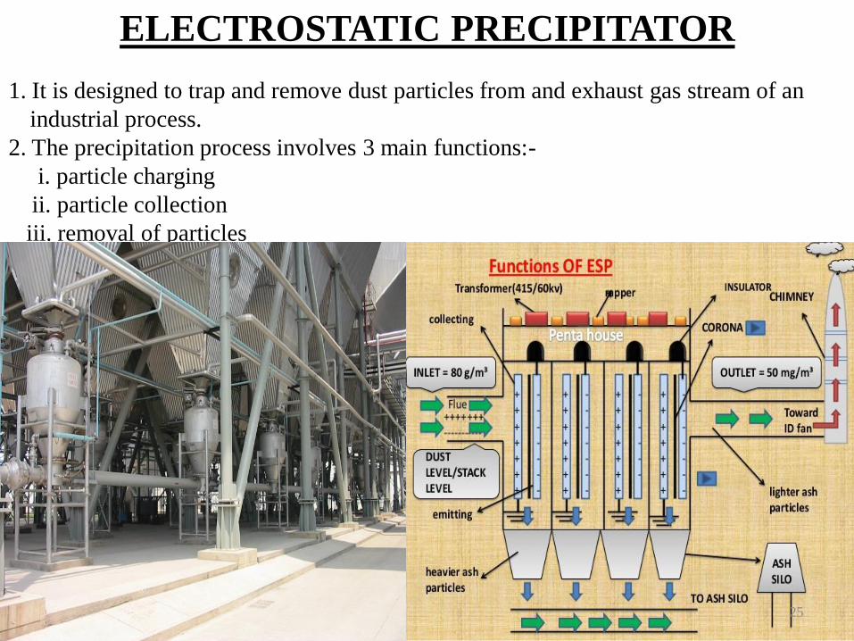
ELECTROSTATIC PRECIPITATOR
1. It is designed to trap and remove dust particles from and exhaust gas stream of an
industrial process.
2. The precipitation process involves 3 main functions:-
i. particle charging
ii. particle collection
iii. removal of particles
25
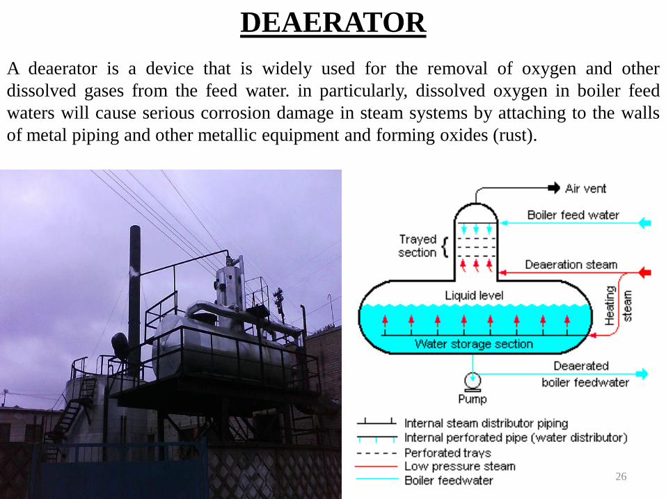
DEAERATOR
A deaerator is a device that is widely used for the removal of oxygen and other
dissolved gases from the feed water. in particularly, dissolved oxygen in boiler feed
waters will cause serious corrosion damage in steam systems by attaching to the walls
of metal piping and other metallic equipment and forming oxides (rust).
26
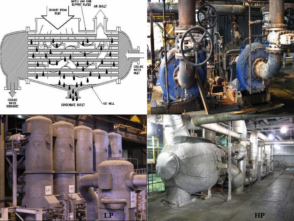
CONDENSER
1. Here the steam is condensed back into water and pumped back to the boiler.
2. This happens via a series of low and high pressure heaters.
CONDENSATE EXTRACTION PUMP
The condensate water is drawn from the condenser by extraction pump and send it
to low pressure feed heater.
LOW PRESSURE FEED HEATER (LP HEATER)
1. Feed water from the condensate extraction pumps pass through low pressure
heater.
2. Steam is used to heat the feed water.
HIGH PRESSURE HEATER
With similar purpose, the high pressure feed heaters are the last stage of feed water
heating before the feed water enters the boiler system at the economizer. 27
CONDEN
SER
CE
P
LP
H
HP
H
28
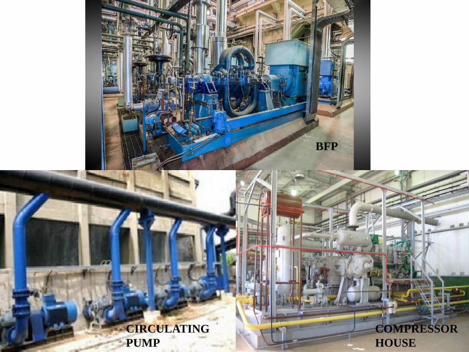
BOILER FEED PUMP
1. The boiler feed pump pumps the water into the boiler, overcoming
pressure of 150 kg/cm².
2. The pump is driven by an electric motor.
3. The pump run in 4130 rpm and the motor runs in 1490 rpm.
CIRCULATING WATER PUMPS
The circulating water pumps are used to circulate the water from
cooling tower to the condenser and back again.
29
COMPRESSOR HOUSE
1. The main purpose of the compressor house is to provide or supply
the high pressure air to the different components in plant.
2. There are 2 types of compressed air:-
i. SERVICE AIR which contains moisture and is supply to ash handling plant
and other services where moisture not damage any equipment.
ii. INSTRUMENT AIR which contain no moisture in air and this air is
used in Pneumatic valves.
30
BFP
CIRCULATING
PUMP
COMPRESSOR
HOUSE31
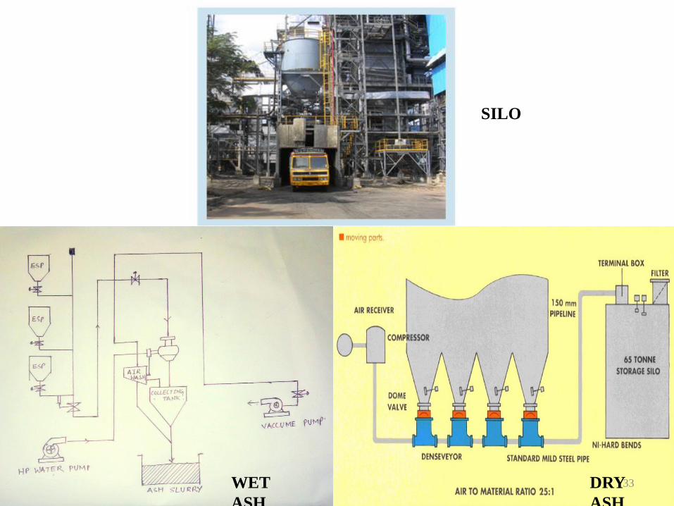
After the coal is burn the ash of the coal remains in the esp system
so to remove that ash from the plant there is an ash handling plant
just near the boiler. the wet ash is dumped in dumping area and the
dry ash is used in brick and cement making.
DRY ASH SYSTEM
Fly ash is considered to be collected in esp. hoppers. fly ash from
esp. hoppers extracted by vacuum pumps up to intermediate surge
hopper cum bag filter for further dry conveying to fly ash silo.
WET ASH SYSTEM
Bottom ash slurry and fly ash slurry shall be pumped from the
common ash slurry sump up to the dyke area which is located at a
distance from slurry pump house.32
ASH HANDLING PLANT
DRY
ASH
WET
ASH
SILO
33
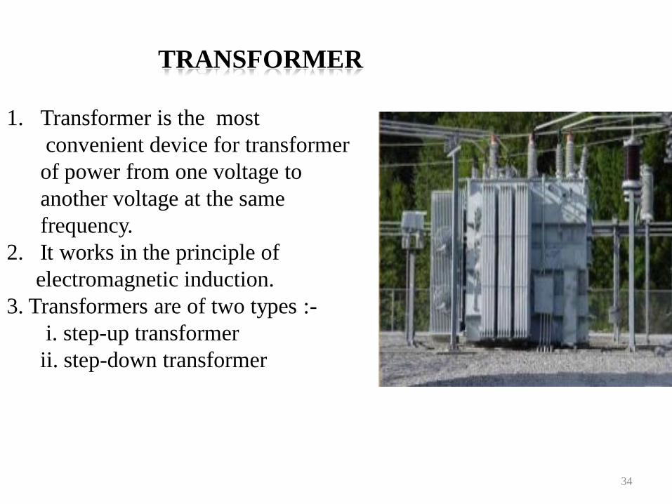
1. Transformer is the most
convenient device for transformer
of power from one voltage to
another voltage at the same
frequency.
2. It works in the principle of
electromagnetic induction.
3. Transformers are of two types :-
i. step-up transformer
ii. step-down transformer
34
TRANSFORMER
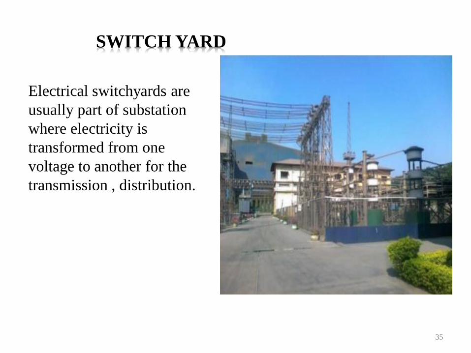
Electrical switchyards are
usually part of substation
where electricity is
transformed from one
voltage to another for the
transmission , distribution.
35
SWITCH YARD
UNIT-II
INTERNAL COMBUSTION ENGINE
PLANT
36
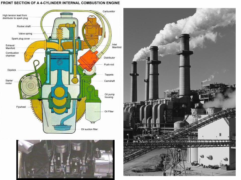
INTERNAL COMBUSTION
ENGINE PLANT:
• DIESEL POWER PLANT• The oil engines and gas engines are called Internal
Combustion Engines. In IC engines fuels burn inside the engine
and the products of combustion form the working fluid that
generates mechanical power. Whereas, in Gas Turbines the
combustion occurs in another chamber and hot working fluid
containing thermal energy is admitted in turbine.
37
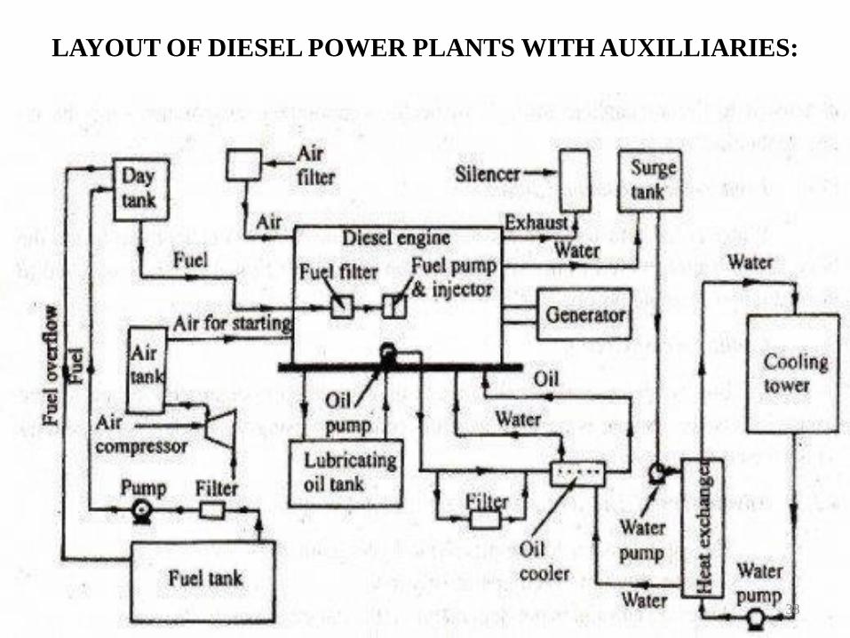
LAYOUT OF DIESEL POWER PLANTS WITH AUXILLIARIES:
38
FUEL SUPPLY SYSTEM:
The five essential functions of a fuel injection system are:
• To deliver oil from the storage to the fuel injector.
• To raise the fuel pressure to the level required for atomization.
• To measure and control the amount of fuel admitted in each cycle.
• To control time of injection.
• To spray fuel into the cylinder in atomized form for thorough mixing and burning.
39
• The above functions can be achieved in a
variety of ways. The following are the
systems, which are usual on power station
diesels:
– Common Rail.
– Individual Pump Injection.
– Distributor.
40
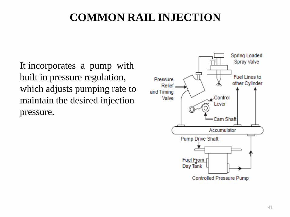
COMMON RAIL INJECTION
It incorporates a pump with
built in pressure regulation,
which adjusts pumping rate to
maintain the desired injection
pressure.
41
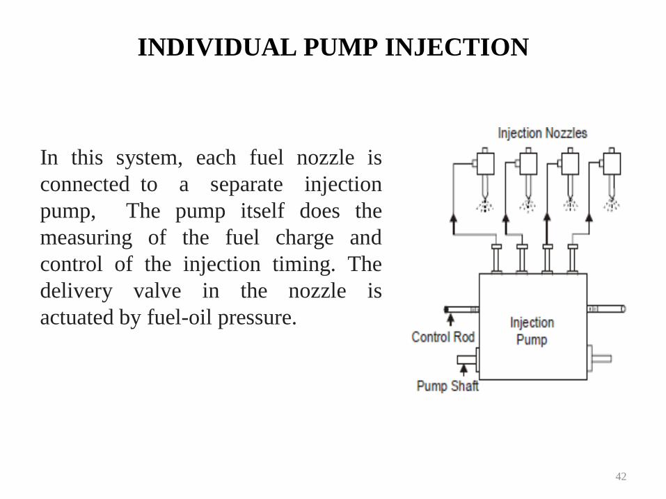
INDIVIDUAL PUMP INJECTION
In this system, each fuel nozzle is
connected to a separate injection
pump, The pump itself does the
measuring of the fuel charge and
control of the injection timing. The
delivery valve in the nozzle is
actuated by fuel-oil pressure.
42
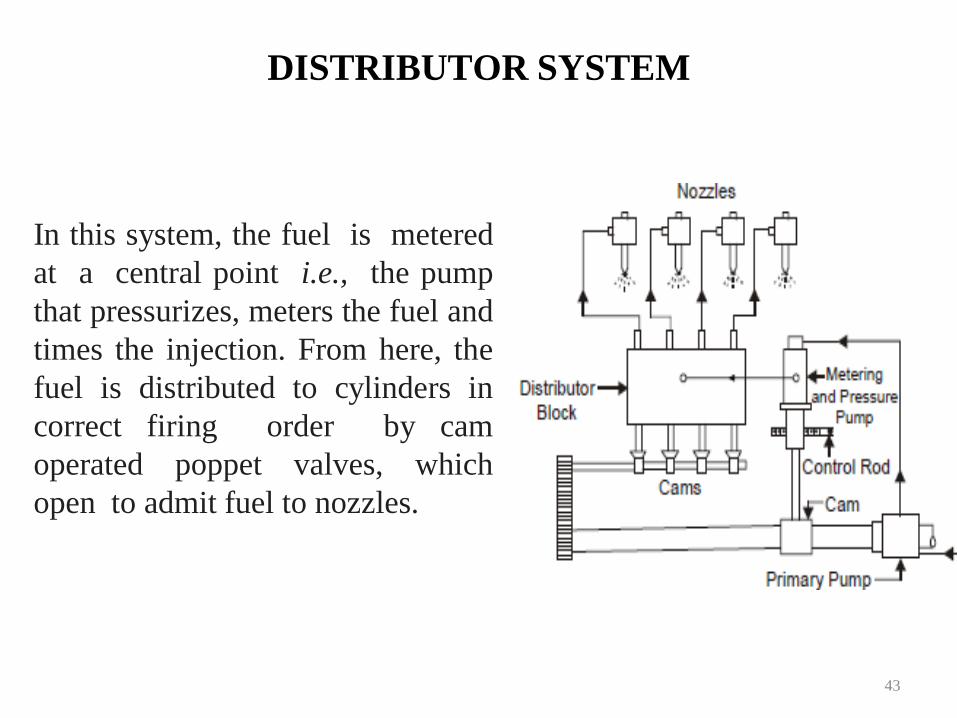
DISTRIBUTOR SYSTEM
In this system, the fuel is metered
at a central point i.e., the pump
that pressurizes, meters the fuel and
times the injection. From here, the
fuel is distributed to cylinders in
correct firing order by cam
operated poppet valves, which
open to admit fuel to nozzles.
43
LUBRICATION SYSTEM
The main function of lubricant is to,
• To reduce friction and wear between the parts having relative
motion by minimizing the force of friction and ensures smooth
running of parts.
• To seal a space adjoining the surfaces such as piston rings
and cylinder liner.
• To clean the surface by carrying away the carbon and metal
particles caused by wear.
• To absorb shock between bearings and other parts and
consequently reduce noise.
44
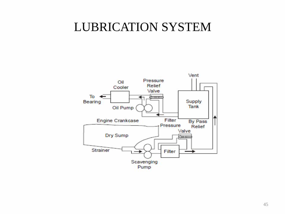
LUBRICATION SYSTEM
45
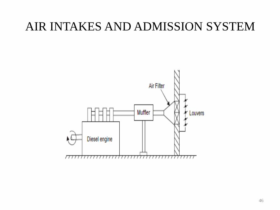
AIR INTAKES AND ADMISSION SYSTEM
46
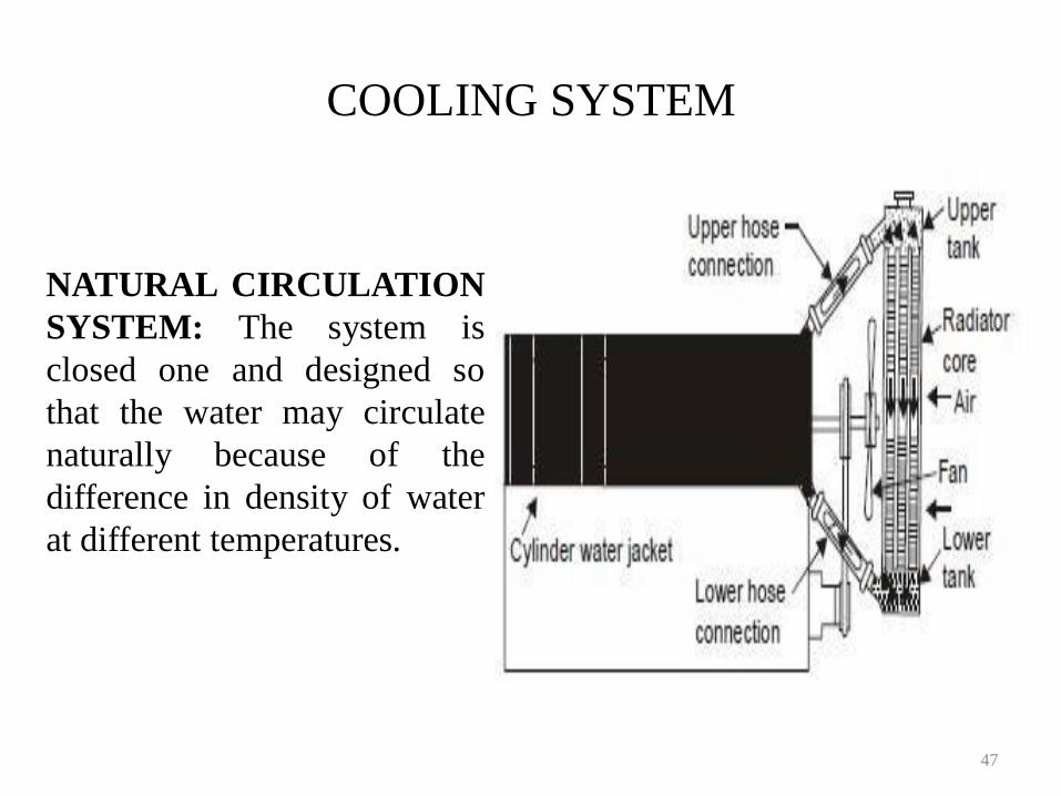
COOLING SYSTEM
NATURAL CIRCULATION
SYSTEM: The system is
closed one and designed so
that the water may circulate
naturally because of the
difference in density of water
at different temperatures.
47
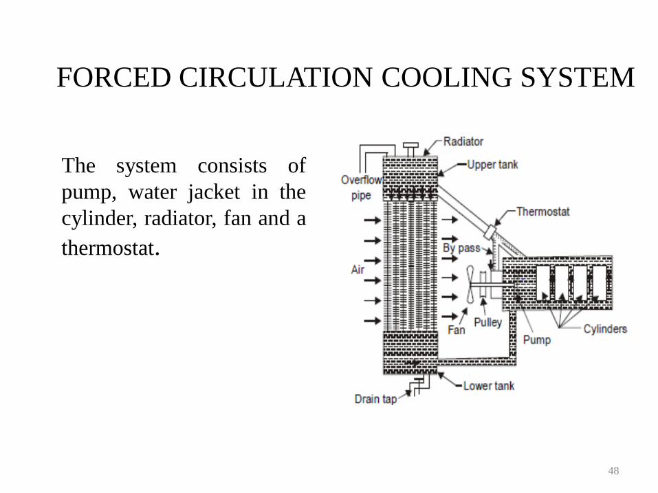
FORCED CIRCULATION COOLING SYSTEM
The system consists of
pump, water jacket in the
cylinder, radiator, fan and a
thermostat.
48
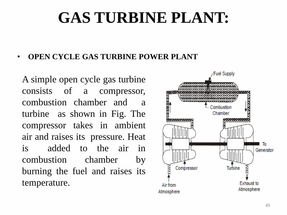
GAS TURBINE PLANT:
• OPEN CYCLE GAS TURBINE POWER PLANT
49
A simple open cycle gas turbine
consists of a compressor,
combustion chamber and a
turbine as shown in Fig. The
compressor takes in ambient
air and raises its pressure. Heat
is added to the air in
combustion chamber by
burning the fuel and raises its
temperature.
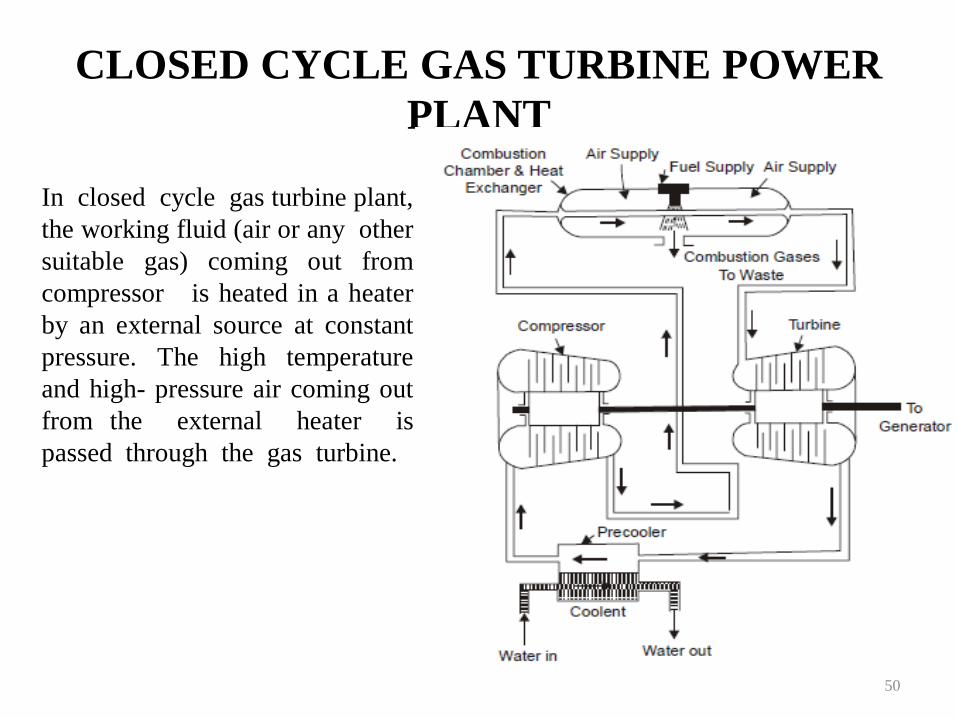
CLOSED CYCLE GAS TURBINE POWER
PLANT
50
In closed cycle gas turbine plant,
the working fluid (air or any other
suitable gas) coming out from
compressor is heated in a heater
by an external source at constant
pressure. The high temperature
and high- pressure air coming out
from the external heater is
passed through the gas turbine.
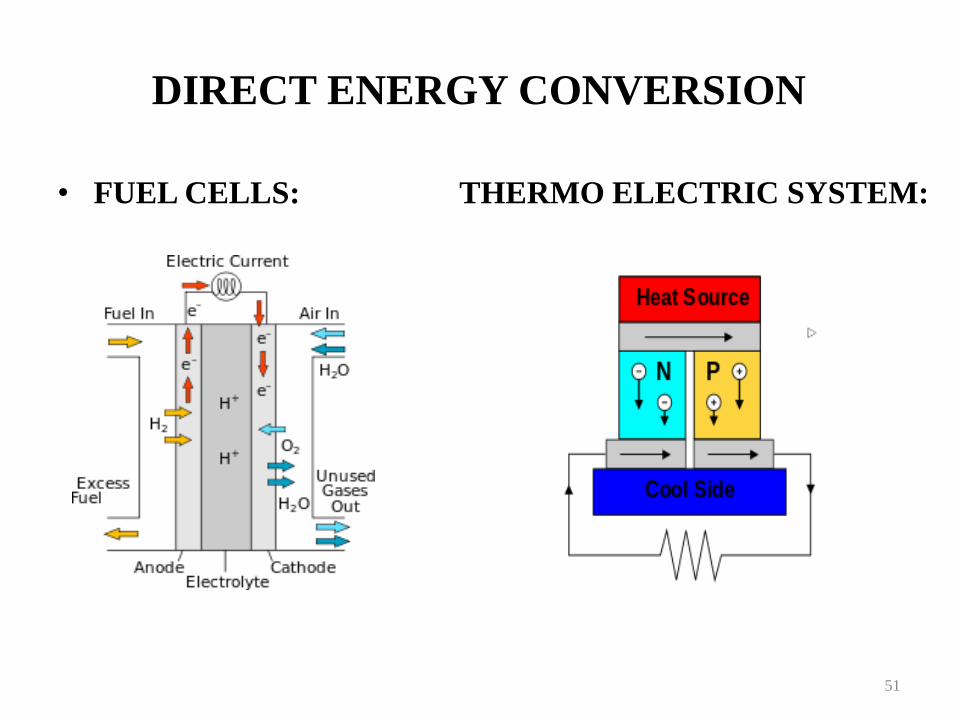
DIRECT ENERGY CONVERSION
• FUEL CELLS: THERMO ELECTRIC SYSTEM:
51
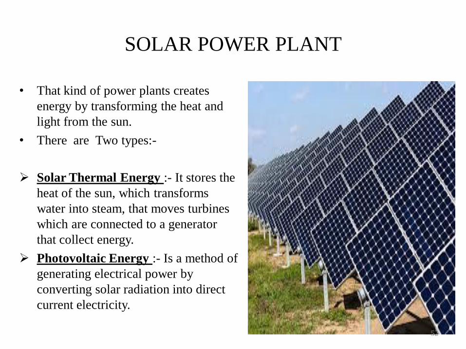
SOLAR POWER PLANT
• That kind of power plants creates
energy by transforming the heat and
light from the sun.
• There are Two types:-
Solar Thermal Energy :- It stores the
heat of the sun, which transforms
water into steam, that moves turbines
which are connected to a generator
that collect energy.
Photovoltaic Energy :- Is a method of
generating electrical power by
converting solar radiation into direct
current electricity.
52
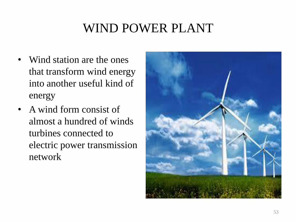
WIND POWER PLANT
• Wind station are the ones
that transform wind energy
into another useful kind of
energy
• A wind form consist of
almost a hundred of winds
turbines connected to
electric power transmission
network
53
UNIT-III
HYDRO ELECTRIC POWER
PLANT
54
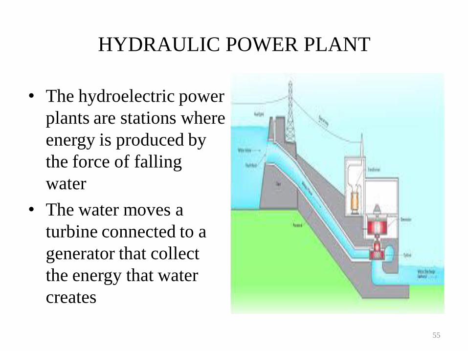
HYDRAULIC POWER PLANT
• The hydroelectric power
plants are stations where
energy is produced by
the force of falling
water
• The water moves a
turbine connected to a
generator that collect
the energy that water
creates
55
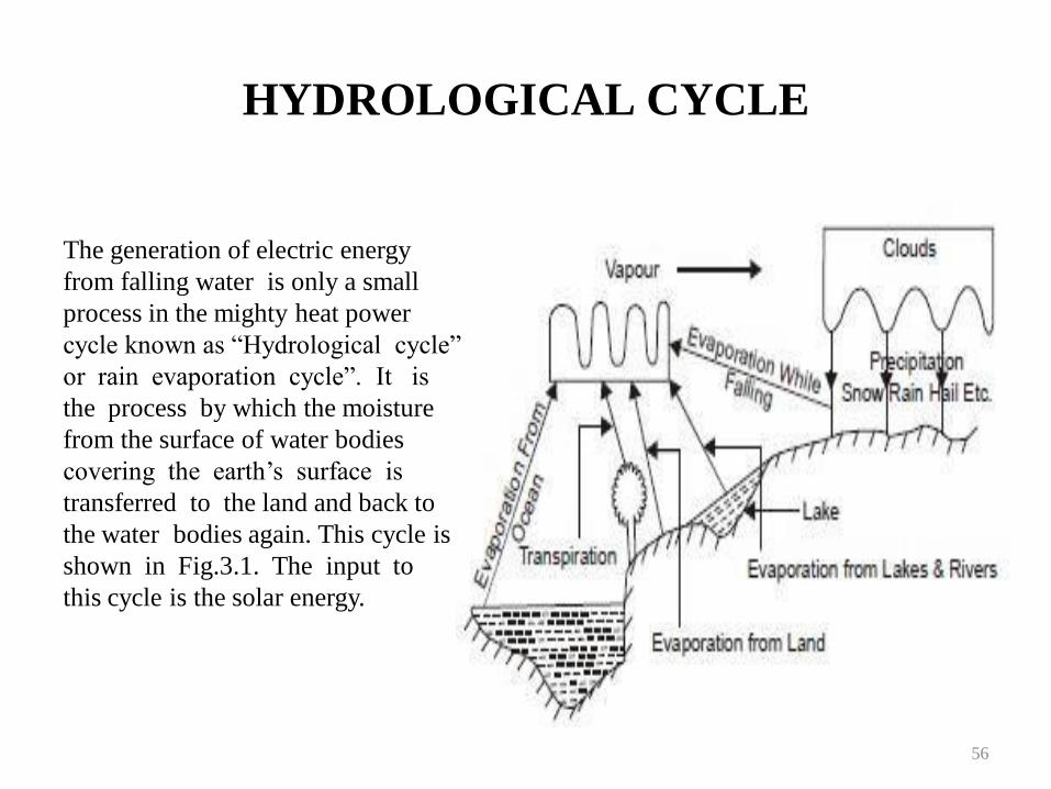
HYDROLOGICAL CYCLE
56
The generation of electric energy
from falling water is only a small
process in the mighty heat power
cycle known as “Hydrological cycle”
or rain evaporation cycle”. It is
the process by which the moisture
from the surface of water bodies
covering the earth‟s surface is
transferred to the land and back to
the water bodies again. This cycle is
shown in Fig.3.1. The input to
this cycle is the solar energy.
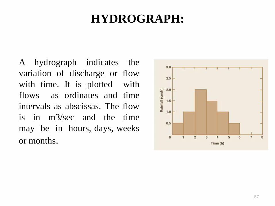
HYDROGRAPH:
A hydrograph indicates the
variation of discharge or flow
with time. It is plotted with
flows as ordinates and time
intervals as abscissas. The flow
is in m3/sec and the time
may be in hours, days, weeks
or months.
57
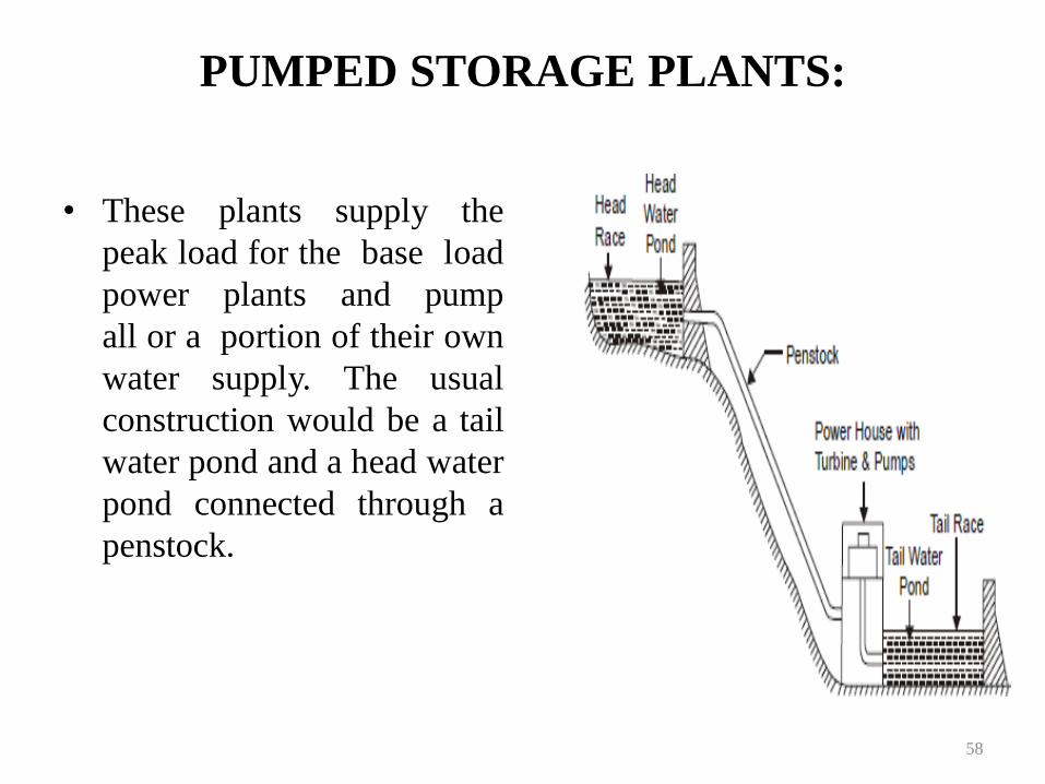
PUMPED STORAGE PLANTS:
• These plants supply the
peak load for the base load
power plants and pump
all or a portion of their own
water supply. The usual
construction would be a tail
water pond and a head water
pond connected through a
penstock.
58
TYPES OF DAMS:
• MASANORY
DAMS
• Solid gravity dams
• Buttress dams
• Arch dams
• EARTHFILL DAMS
• Earth fill dams
• Rock fill dams
59
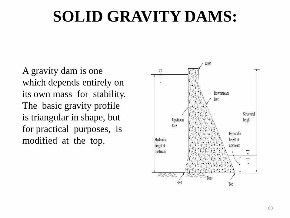
SOLID GRAVITY DAMS:
60
A gravity dam is one
which depends entirely on
its own mass for stability.
The basic gravity profile
is triangular in shape, but
for practical purposes, is
modified at the top.
TYPES OF SPILLWAYS:
• Overflow spillway
• Chute spillway
• Shaft spillway
• Siphon spillway
61
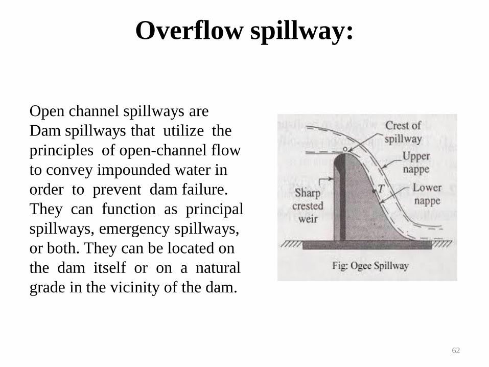
Overflow spillway:
62
Open channel spillways are
Dam spillways that utilize the
principles of open-channel flow
to convey impounded water in
order to prevent dam failure.
They can function as principal
spillways, emergency spillways,
or both. They can be located on
the dam itself or on a natural
grade in the vicinity of the dam.
UNIT-IV
NUCLEAR POWER STATION
63
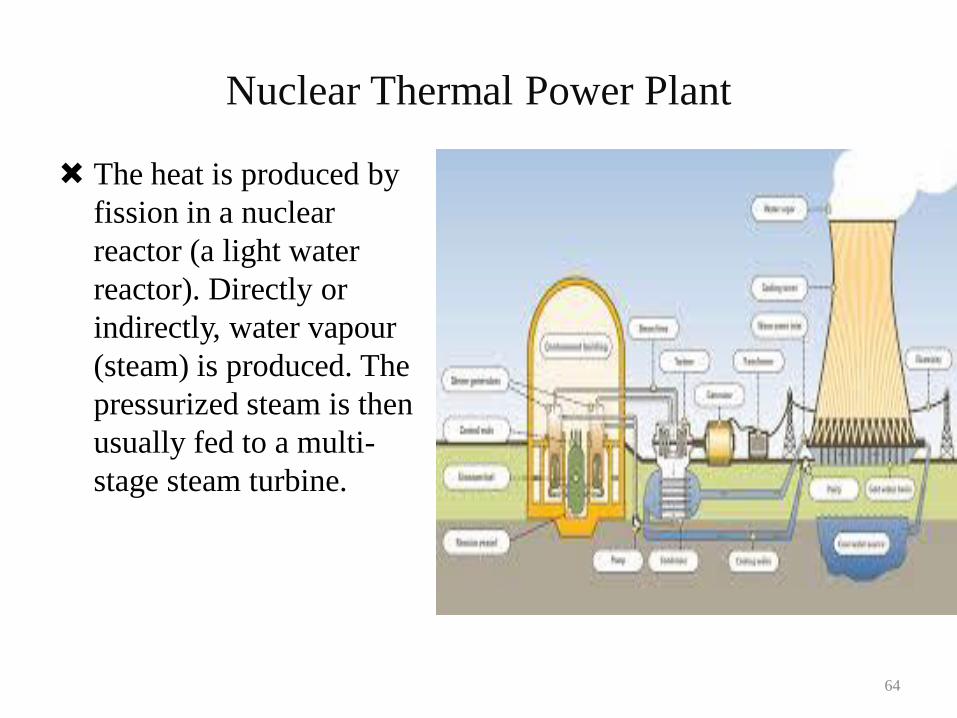
Nuclear Thermal Power Plant
The heat is produced by
fission in a nuclear
reactor (a light water
reactor). Directly or
indirectly, water vapour
(steam) is produced. The
pressurized steam is then
usually fed to a multi-
stage steam turbine.
64
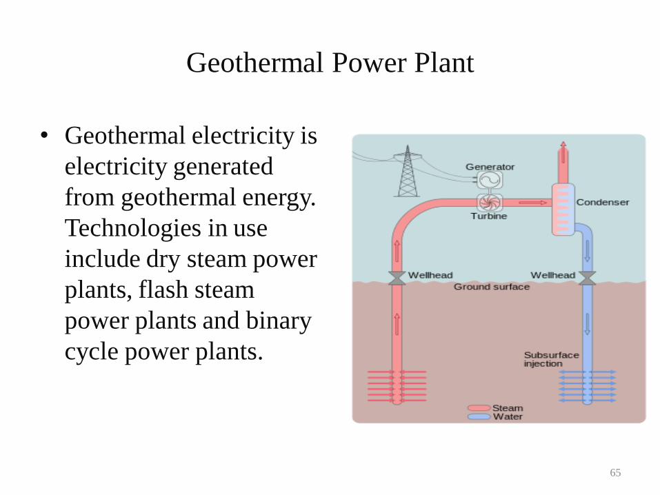
Geothermal Power Plant
• Geothermal electricity is
electricity generated
from geothermal energy.
Technologies in use
include dry steam power
plants, flash steam
power plants and binary
cycle power plants.
65
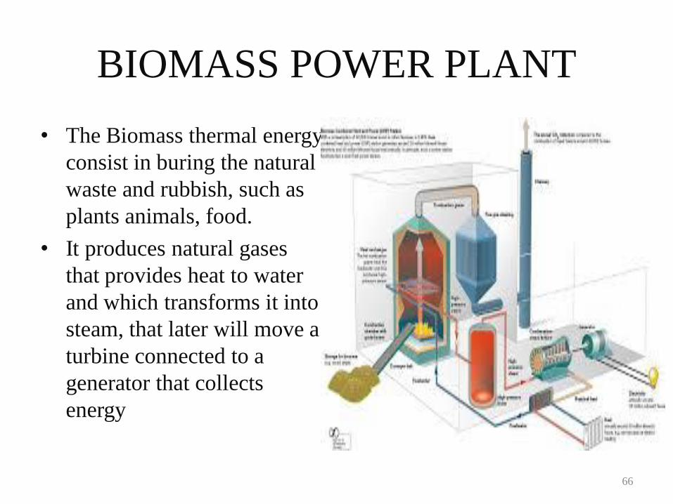
BIOMASS POWER PLANT
• The Biomass thermal energy
consist in buring the natural
waste and rubbish, such as
plants animals, food.
• It produces natural gases
that provides heat to water
and which transforms it into
steam, that later will move a
turbine connected to a
generator that collects
energy
66
Nuclear Power – Need and Future
Outline
• Economics of Nuclear Energy
• Basics of a Power Plant
• Heat From Fission
• History of Nuclear Power
• Current Commercial Nuclear Reactor
Designs
• Nuclear Fuel Cycle
• Future Reactor Designs
• Policy Issues
• Conclusions
68
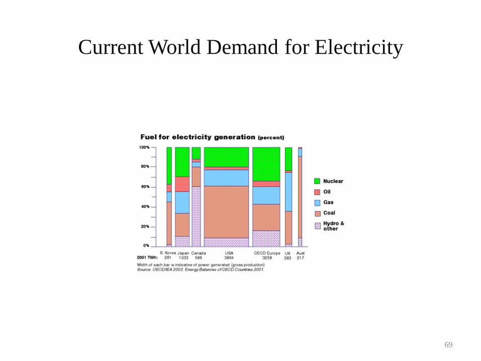
Current World Demand for Electricity
69
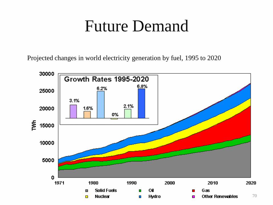
Future Demand
Projected changes in world electricity generation by fuel, 1995 to 2020
70
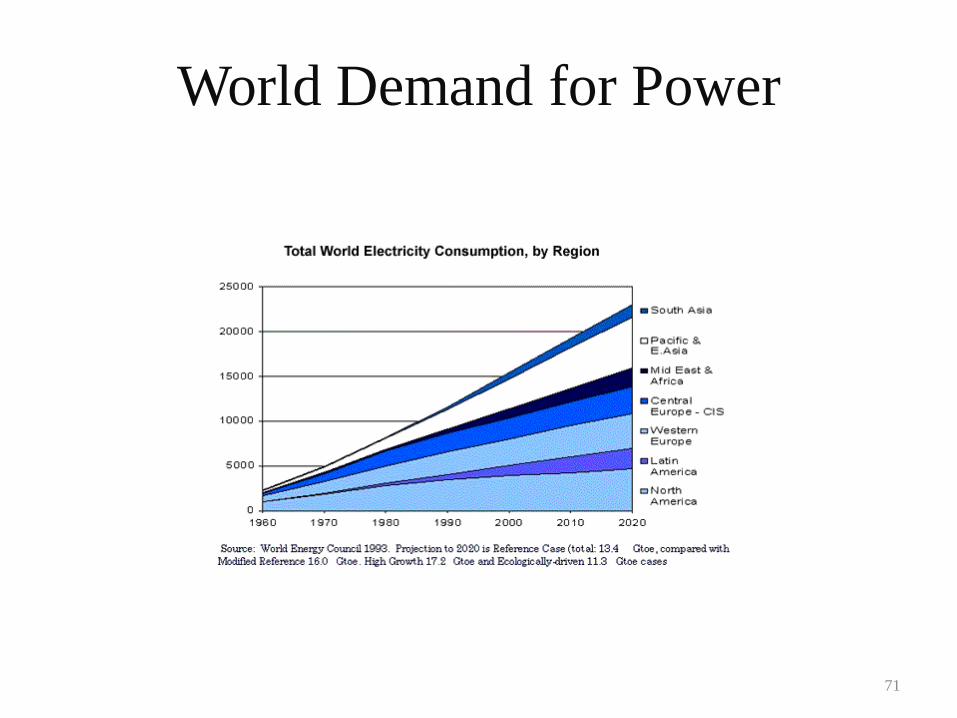
World Demand for Power
71
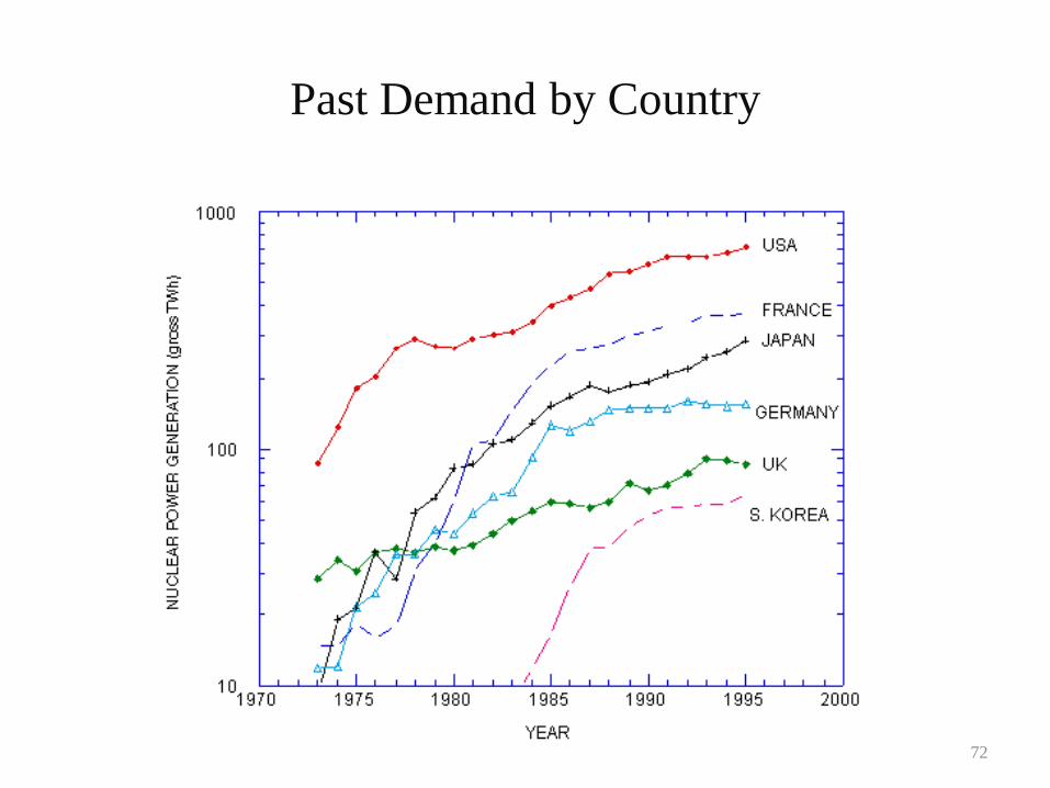
Past Demand by Country
72
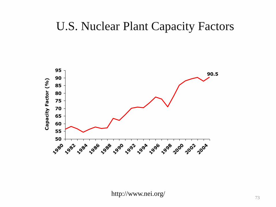
U.S. Nuclear Plant Capacity Factors
90.5
50
55
60
65
70
75
80
85
90
95
1980
1982
1984
1986
1988
1990
1992
1994
1996
1998
2000
2002
2004
Ca
pa
cit
y F
acto
r (
%)
http://www.nei.org/73
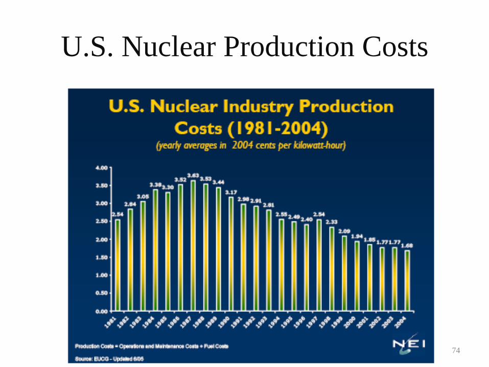
U.S. Nuclear Production Costs
74
1995 1996 1997 1998 1999 2000 2001 2002 2003 2004
0.0
1.0
2.0
3.0
4.0
5.0
6.0
7.0
8.0
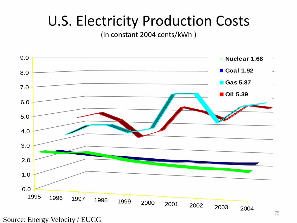
9.0 Nuclear 1.68
Coal 1.92
Gas 5.87
Oil 5.39
Source: Energy Velocity / EUCG
U.S. Electricity Production Costs(in constant 2004 cents/kWh )
75
0%
20%
40%
60%
80%
100%
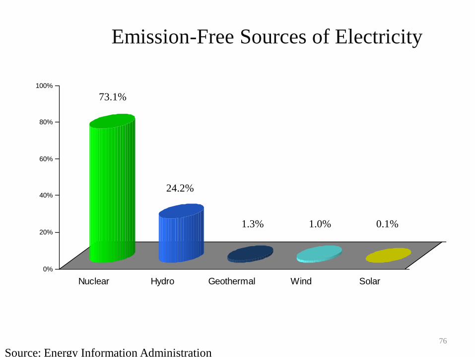
Nuclear Hydro Geothermal Wind Solar
Emission-Free Sources of Electricity
Source: Energy Information Administration
73.1%
24.2%
1.3% 1.0% 0.1%
76
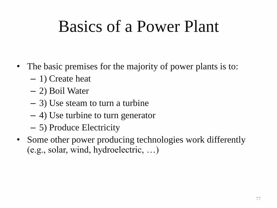
Basics of a Power Plant
• The basic premises for the majority of power plants is to:
– 1) Create heat
– 2) Boil Water
– 3) Use steam to turn a turbine
– 4) Use turbine to turn generator
– 5) Produce Electricity
• Some other power producing technologies work differently (e.g., solar, wind, hydroelectric, …)
77
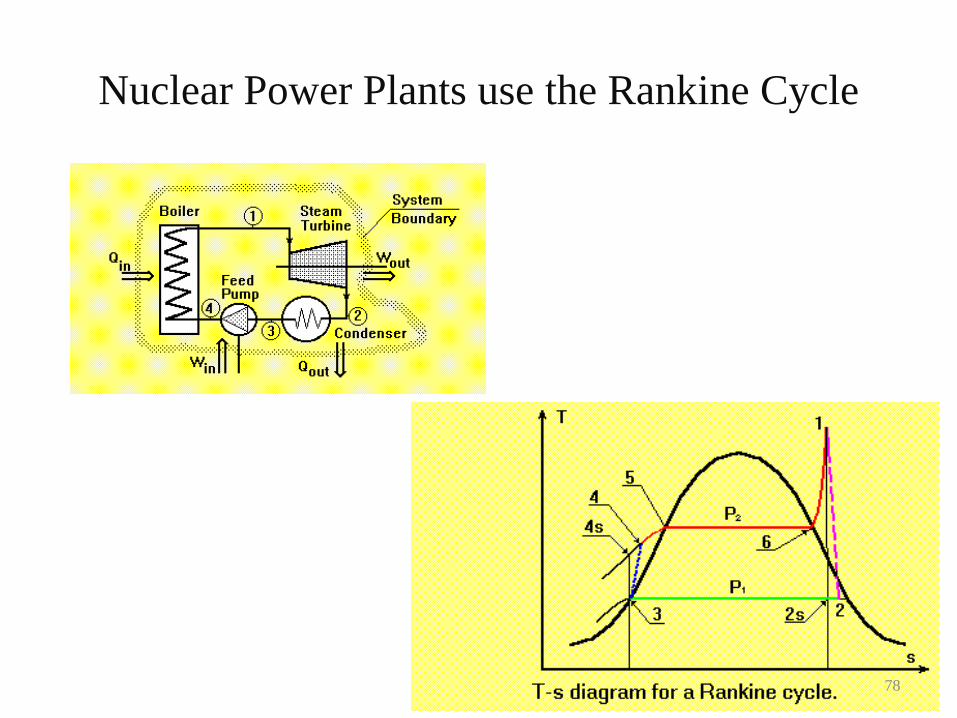
Nuclear Power Plants use the Rankine Cycle
78
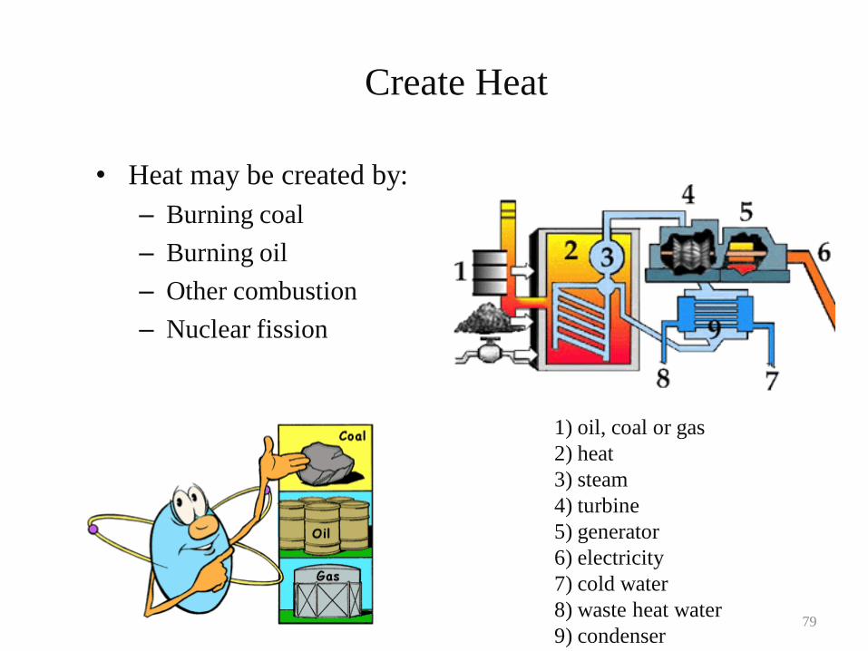
Create Heat
• Heat may be created by:
– Burning coal
– Burning oil
– Other combustion
– Nuclear fission
1) oil, coal or gas
2) heat
3) steam
4) turbine
5) generator
6) electricity
7) cold water
8) waste heat water
9) condenser79
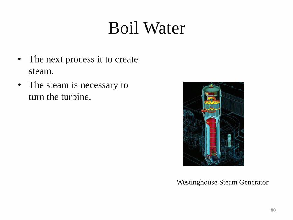
Boil Water
• The next process it to create
steam.
• The steam is necessary to
turn the turbine.
Westinghouse Steam Generator
80
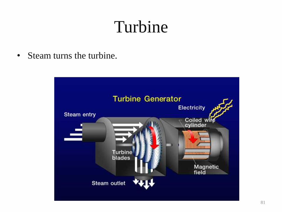
Turbine
• Steam turns the turbine.
81
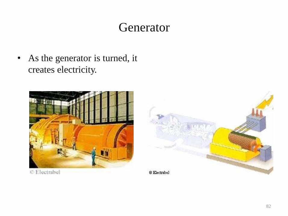
Generator
• As the generator is turned, it
creates electricity.
82
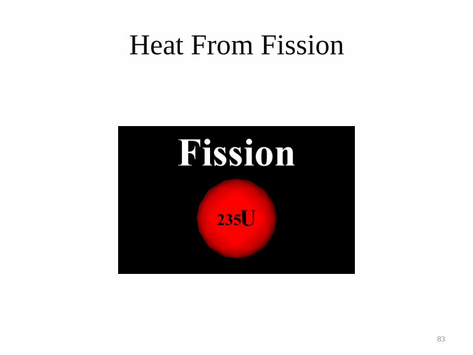
Heat From Fission
83
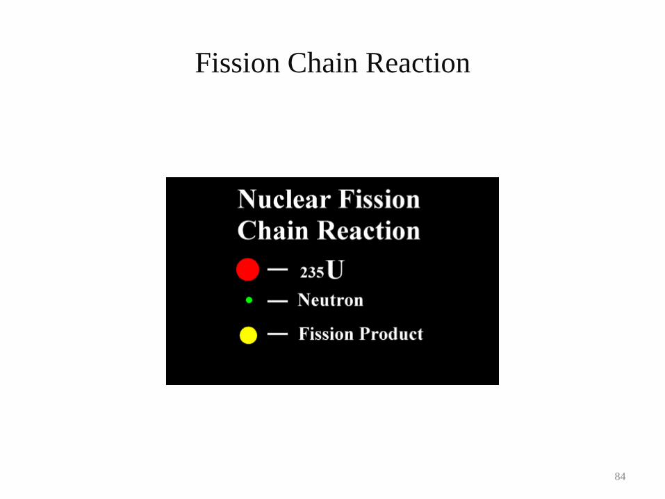
Fission Chain Reaction
84
Nuclear History
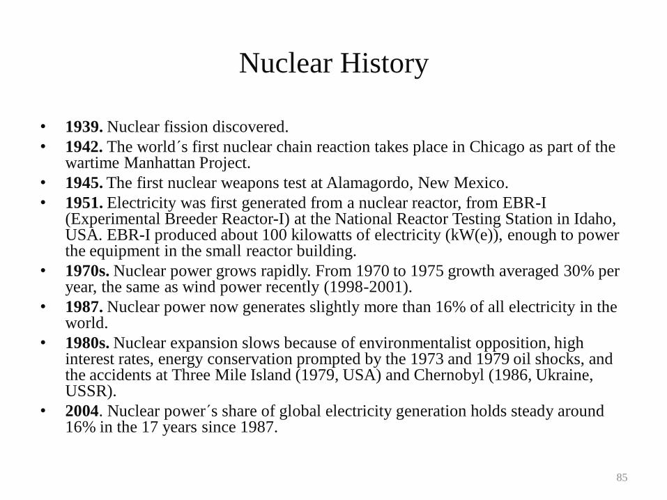
• 1939. Nuclear fission discovered.
• 1942. The world´s first nuclear chain reaction takes place in Chicago as part of the wartime Manhattan Project.
• 1945. The first nuclear weapons test at Alamagordo, New Mexico.
• 1951. Electricity was first generated from a nuclear reactor, from EBR-I (Experimental Breeder Reactor-I) at the National Reactor Testing Station in Idaho, USA. EBR-I produced about 100 kilowatts of electricity (kW(e)), enough to power the equipment in the small reactor building.
• 1970s. Nuclear power grows rapidly. From 1970 to 1975 growth averaged 30% per year, the same as wind power recently (1998-2001).
• 1987. Nuclear power now generates slightly more than 16% of all electricity in the world.
• 1980s. Nuclear expansion slows because of environmentalist opposition, high interest rates, energy conservation prompted by the 1973 and 1979 oil shocks, and the accidents at Three Mile Island (1979, USA) and Chernobyl (1986, Ukraine, USSR).
• 2004. Nuclear power´s share of global electricity generation holds steady around 16% in the 17 years since 1987.
85
Current Commercial Nuclear Reactor Designs
• Pressurized Water Reactor (PWR)
• Boiling Water Reactor (BWR)
• Gas Cooled Fast Reactor
• Pressurized Heavy Water Reactor (CANDU)
• Light Water Graphite Reactor (RBMK)
• Fast Neutron Reactor (FBR)
86
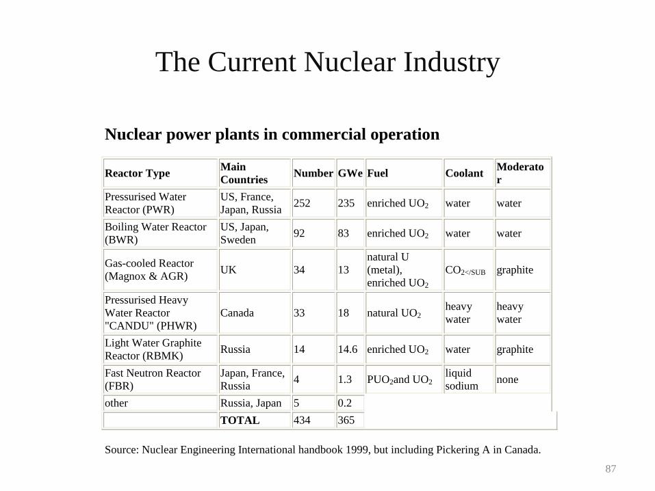
The Current Nuclear Industry
Nuclear power plants in commercial operation
Reactor Type Main
Countries Number GWe Fuel Coolant
Moderato
r
Pressurised Water
Reactor (PWR)
US, France,
Japan, Russia 252 235 enriched UO2 water water
Boiling Water Reactor
(BWR)
US, Japan,
Sweden 92 83 enriched UO2 water water
Gas-cooled Reactor
(Magnox & AGR) UK 34 13
natural U
(metal),
enriched UO2
CO2</SUB graphite
Pressurised Heavy
Water Reactor
"CANDU" (PHWR)
Canada 33 18 natural UO2 heavy
water
heavy
water
Light Water Graphite
Reactor (RBMK) Russia 14 14.6 enriched UO2 water graphite
Fast Neutron Reactor
(FBR)
Japan, France,
Russia 4 1.3 PUO2and UO2
liquid
sodium none
other Russia, Japan 5 0.2
TOTAL 434 365
Source: Nuclear Engineering International handbook 1999, but including Pickering A in Canada.
87
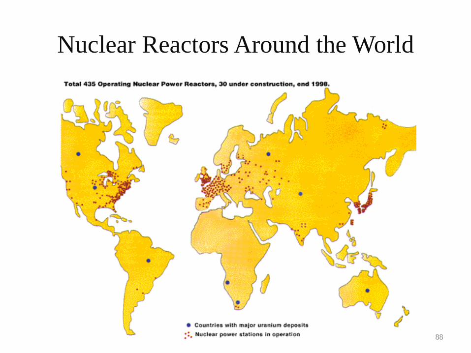
Nuclear Reactors Around the World
88
PWR
89
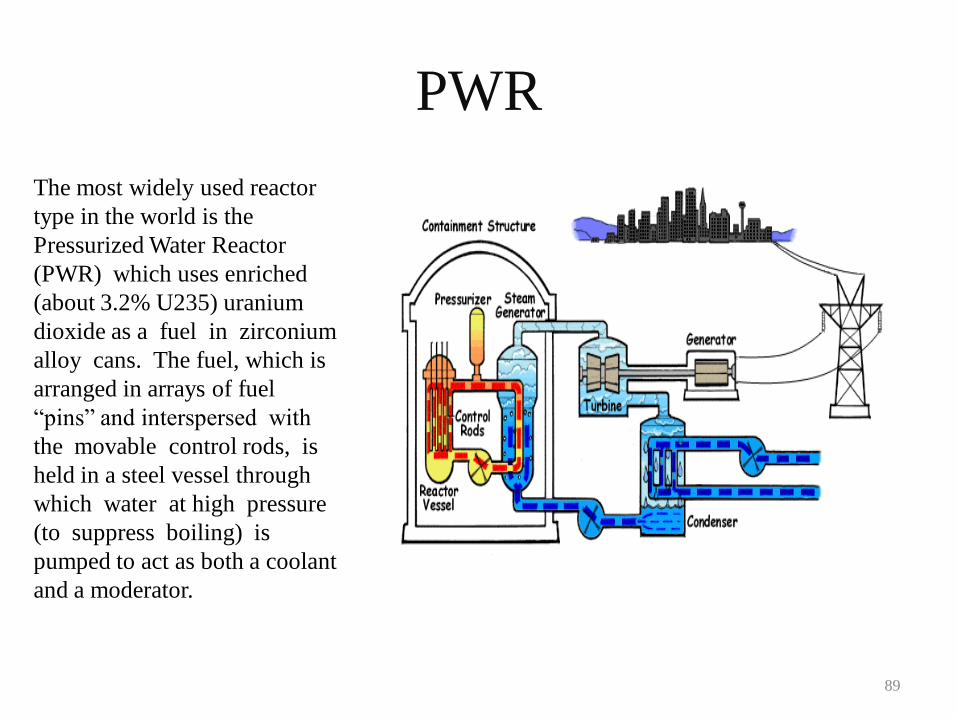
The most widely used reactor
type in the world is the
Pressurized Water Reactor
(PWR) which uses enriched
(about 3.2% U235) uranium
dioxide as a fuel in zirconium
alloy cans. The fuel, which is
arranged in arrays of fuel
“pins” and interspersed with
the movable control rods, is
held in a steel vessel through
which water at high pressure
(to suppress boiling) is
pumped to act as both a coolant
and a moderator.
BWR
90
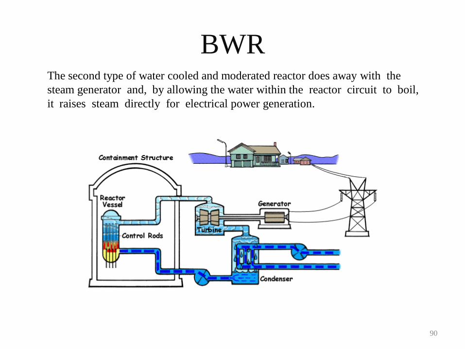
The second type of water cooled and moderated reactor does away with the
steam generator and, by allowing the water within the reactor circuit to boil,
it raises steam directly for electrical power generation.
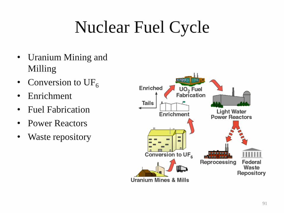
Nuclear Fuel Cycle
• Uranium Mining and
Milling
• Conversion to UF6
• Enrichment
• Fuel Fabrication
• Power Reactors
• Waste repository
91
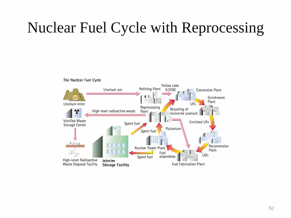
Nuclear Fuel Cycle with Reprocessing
92
Future Reactor Designs
• Research is currently being conducted for design of the
next generation of nuclear reactor designs.
• The next generation designs focus on:
– Proliferation resistance of fuel
– Passive safety systems
– Improved fuel efficiency (includes breeding)
– Minimizing nuclear waste
– Improved plant efficiency (e.g., Brayton cycle)
– Hydrogen production
– Economics
93
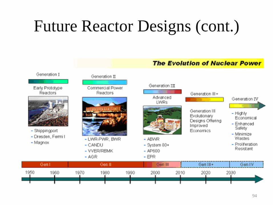
Future Reactor Designs (cont.)
94
Generation III Reactor Designs
• Pebble Bed Reactor
• Advanced Boiling Water Reactor (ABWR)
• AP600
• System 80+
95
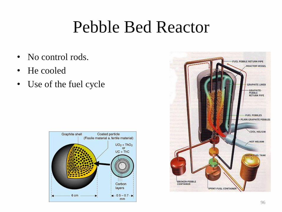
Pebble Bed Reactor
• No control rods.
• He cooled
• Use of the fuel cycle
96
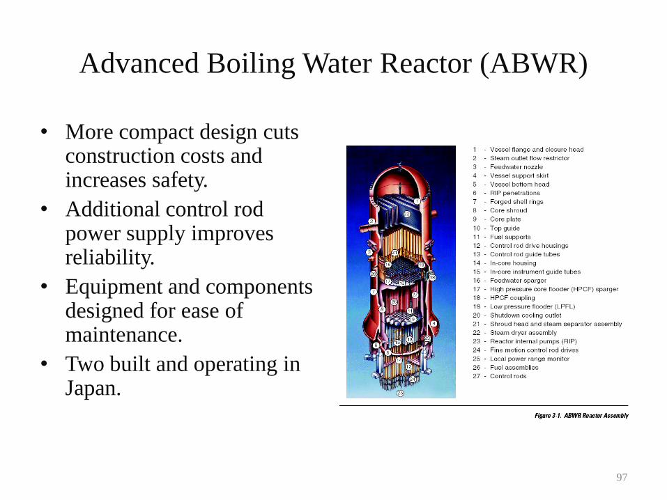
Advanced Boiling Water Reactor (ABWR)
• More compact design cuts construction costs and increases safety.
• Additional control rod power supply improves reliability.
• Equipment and components designed for ease of maintenance.
• Two built and operating in Japan.
97
Gen IV Reactors
• Themes in Gen IV Reactors
• Gas Cooled Fast Reactor (GFR)
• Very High Temperature Reactor (VHTR)
• Supercritical Water Cooled Reactor (SCWR)
• Sodium Cooled Fast Reactor (SFR)
• Lead Cooled Fast Reactor (LFR)
• Molten Salt Reactor (MSR)
98
Themes in Gen IV Reactors
• Hydrogen Production
• Proliferation Resistance
• Closed Fuel Cycle
• Simplification
• Increased safety
99
Hydrogen Production
• Hydrogen is ready to play the lead in the next generation of energy production methods.
• Nuclear heat sources (i.e., a nuclear reactor) have been proposed to aid in the separation of H from H20.
• Hydrogen is thermo chemically generated from water decomposed by nuclear heat at high temperature.
• The IS process is named after the initials of each element used (iodine and sulfur).
100
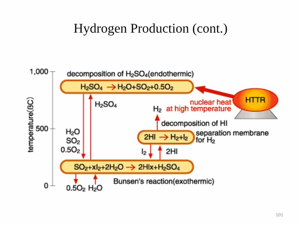
Hydrogen Production (cont.)
101
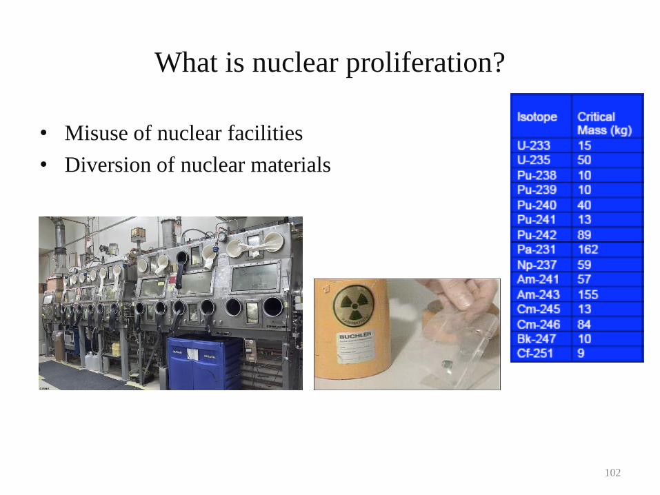
What is nuclear proliferation?
• Misuse of nuclear facilities
• Diversion of nuclear materials
102
Specific Generation IV Design Advantages
– Long fuel cycle - refueling 15-20 years
– Relative small capacity
– Thorough fuel burn up
– Fuel cycle variability
– Actinide burning
– Ability to burn weapons grade fuel
103
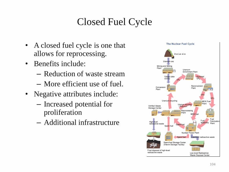
Closed Fuel Cycle
• A closed fuel cycle is one that allows for reprocessing.
• Benefits include:
– Reduction of waste stream
– More efficient use of fuel.
• Negative attributes include:
– Increased potential for proliferation
– Additional infrastructure
104
Simplification
• Efforts are made to simplify the design of Gen
IV reactors. This leads to:
– Reduced capitol costs
– Reduced construction times
– Increased safety (less things can fail)
105
Increased Safety
• Increased safety is always a priority.
• Some examples of increased safety:
– Natural circulation in systems
– Reduction of piping
– Incorporation of pumps within reactor vessel
– Lower pressures in reactor vessel (liquid metal cooled
reactors)
106
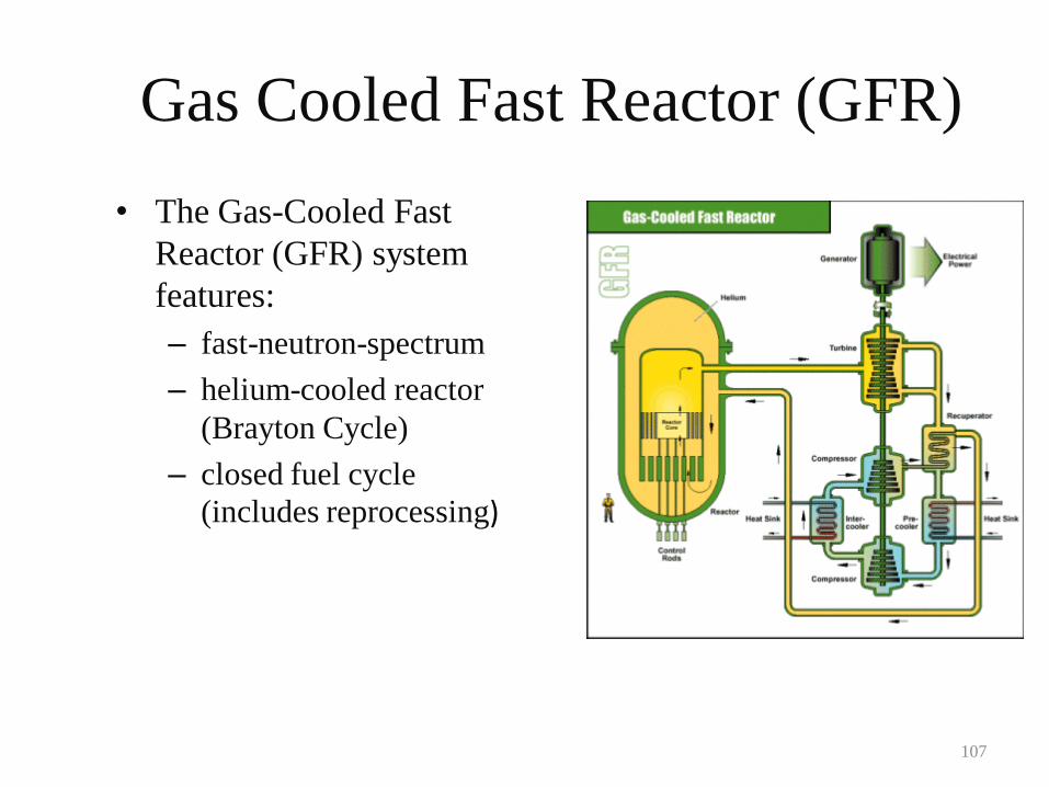
Gas Cooled Fast Reactor (GFR)
• The Gas-Cooled Fast
Reactor (GFR) system
features:
– fast-neutron-spectrum
– helium-cooled reactor
(Brayton Cycle)
– closed fuel cycle
(includes reprocessing)
107
Gas Cooled Fast Reactor (GFR)
• Like thermal-spectrum, helium-cooled reactors, the high outlet
temperature of the helium coolant makes it possible to:
– deliver electricity
– produce hydrogen
– process heat with high efficiency.
• The reference reactor is a 288-MWe helium-cooled system
operating with an outlet temperature of 850 degrees Celsius
using a direct Brayton cycle gas turbine for high thermal
efficiency.
108
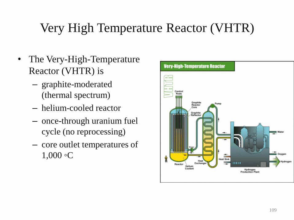
Very High Temperature Reactor (VHTR)
• The Very-High-Temperature
Reactor (VHTR) is
– graphite-moderated
(thermal spectrum)
– helium-cooled reactor
– once-through uranium fuel
cycle (no reprocessing)
– core outlet temperatures of
1,000 ◦C
109
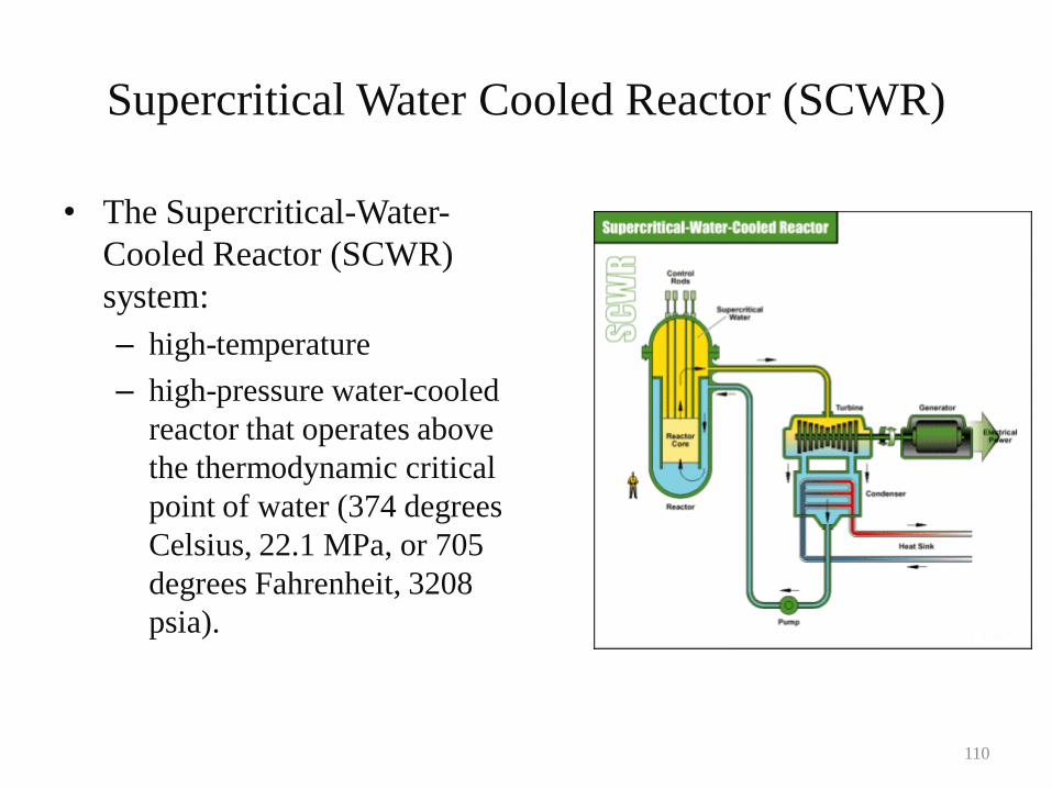
Supercritical Water Cooled Reactor (SCWR)
• The Supercritical-Water-
Cooled Reactor (SCWR)
system:
– high-temperature
– high-pressure water-cooled
reactor that operates above
the thermodynamic critical
point of water (374 degrees
Celsius, 22.1 MPa, or 705
degrees Fahrenheit, 3208
psia).
110
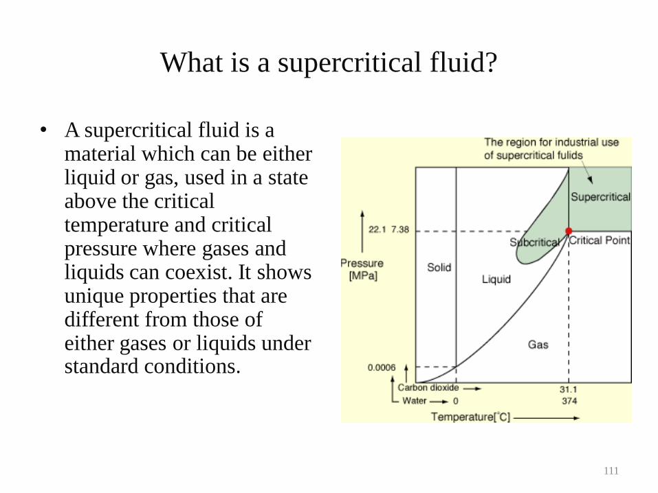
What is a supercritical fluid?
• A supercritical fluid is a material which can be either liquid or gas, used in a state above the critical temperature and critical pressure where gases and liquids can coexist. It shows unique properties that are different from those of either gases or liquids under standard conditions.
111
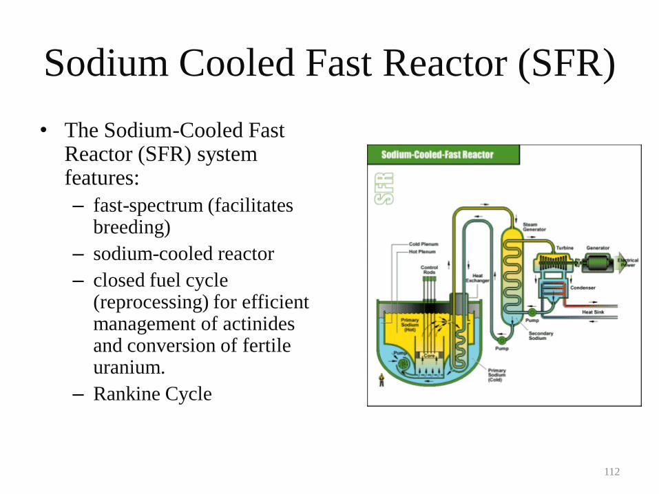
Sodium Cooled Fast Reactor (SFR)
• The Sodium-Cooled Fast Reactor (SFR) system features:
– fast-spectrum (facilitates breeding)
– sodium-cooled reactor
– closed fuel cycle (reprocessing) for efficient management of actinides and conversion of fertile uranium.
– Rankine Cycle
112
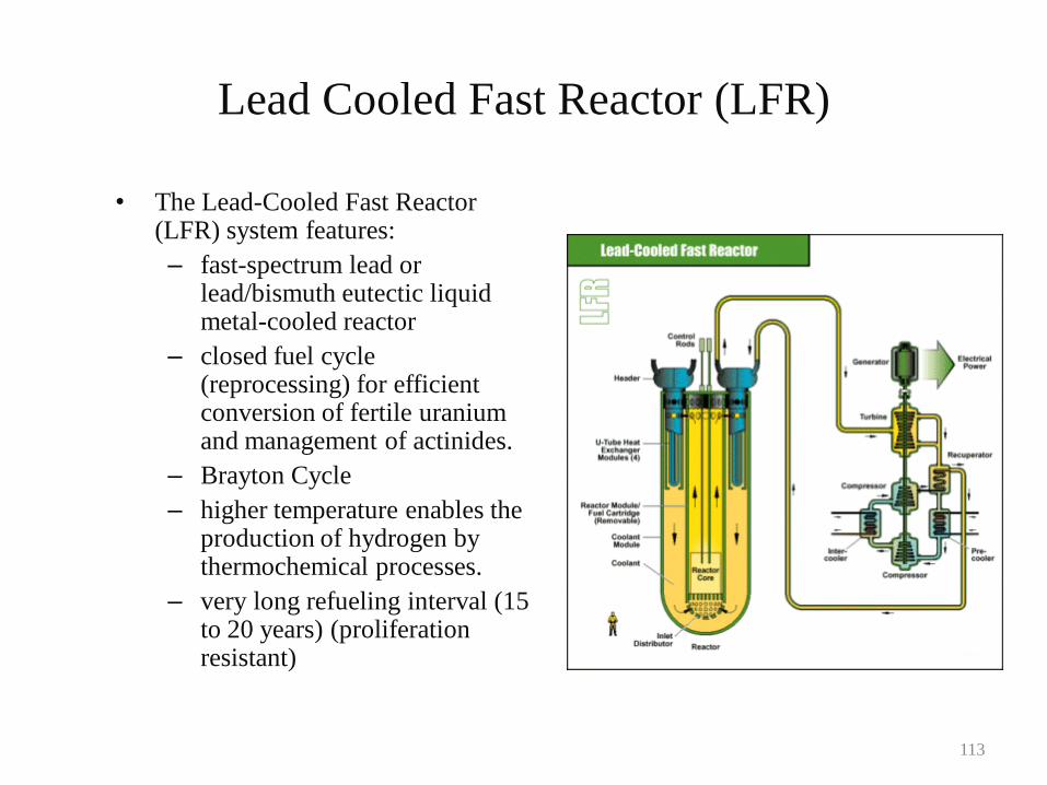
Lead Cooled Fast Reactor (LFR)
• The Lead-Cooled Fast Reactor (LFR) system features:
– fast-spectrum lead or lead/bismuth eutectic liquid metal-cooled reactor
– closed fuel cycle (reprocessing) for efficient conversion of fertile uranium and management of actinides.
– Brayton Cycle
– higher temperature enables the production of hydrogen by thermochemical processes.
– very long refueling interval (15 to 20 years) (proliferation resistant)
113
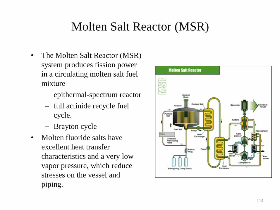
Molten Salt Reactor (MSR)
• The Molten Salt Reactor (MSR)
system produces fission power
in a circulating molten salt fuel
mixture
– epithermal-spectrum reactor
– full actinide recycle fuel
cycle.
– Brayton cycle
• Molten fluoride salts have
excellent heat transfer
characteristics and a very low
vapor pressure, which reduce
stresses on the vessel and
piping.
114
Policy Issues
• Many policy issues exist that affect the viability of the future of nuclear power:
– Licensing
– Risk insurance
– Reprocessing of spent nuclear fuel
– Nuclear waste repository
– Next generation reactor research
– Incorporation of hydrogen production into nuclear fuel cycle
– University nuclear engineering programs
115
Conclusions
• So, what does the future hold?– The demand for electrical power will continue to increase.
– The world reserves of fossil fuels are limited.
– Modern nuclear power plant designs are more inherently safe and may be constructed with less capital cost.
– Fossil fuel-based electricity is projected to account for more than 40% of global greenhouse gas emissions by 2020.
• A 2003 study by MIT predicted that nuclear power growth of three fold will be necessary by 2050.
• U.S. Government has voiced strong support for nuclear power production.
116
118
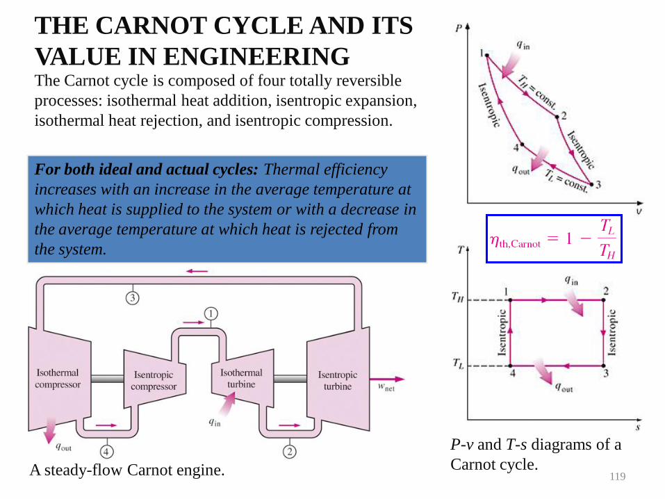
THE CARNOT CYCLE AND ITS
VALUE IN ENGINEERING
P-v and T-s diagrams of a
Carnot cycle.A steady-flow Carnot engine.
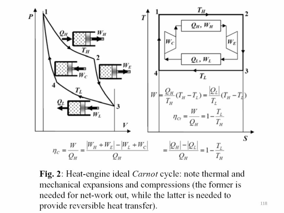
The Carnot cycle is composed of four totally reversible
processes: isothermal heat addition, isentropic expansion,
isothermal heat rejection, and isentropic compression.
For both ideal and actual cycles: Thermal efficiency
increases with an increase in the average temperature at
which heat is supplied to the system or with a decrease in
the average temperature at which heat is rejected from
the system.
119
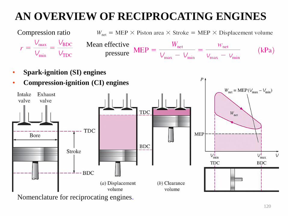
AN OVERVIEW OF RECIPROCATING ENGINES
Nomenclature for reciprocating engines.
• Spark-ignition (SI) engines
• Compression-ignition (CI) engines
Compression ratio
Mean effective
pressure
120
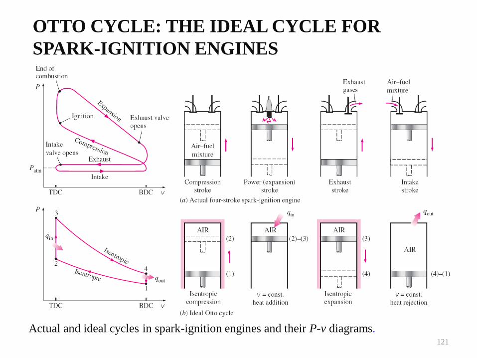
OTTO CYCLE: THE IDEAL CYCLE FOR
SPARK-IGNITION ENGINES
Actual and ideal cycles in spark-ignition engines and their P-v diagrams.121
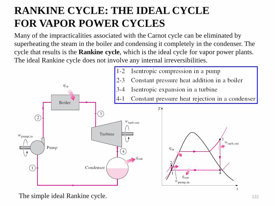
RANKINE CYCLE: THE IDEAL CYCLE
FOR VAPOR POWER CYCLESMany of the impracticalities associated with the Carnot cycle can be eliminated by
superheating the steam in the boiler and condensing it completely in the condenser. The
cycle that results is the Rankine cycle, which is the ideal cycle for vapor power plants.
The ideal Rankine cycle does not involve any internal irreversibilities.
The simple ideal Rankine cycle. 122
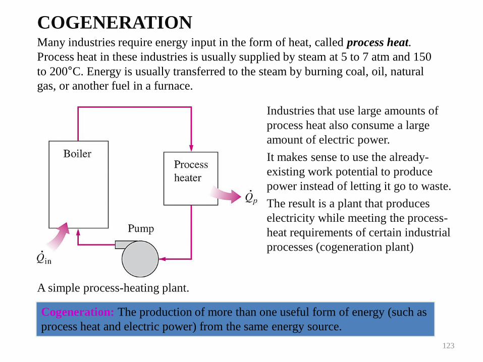
COGENERATION
A simple process-heating plant.
Many industries require energy input in the form of heat, called process heat.
Process heat in these industries is usually supplied by steam at 5 to 7 atm and 150
to 200°C. Energy is usually transferred to the steam by burning coal, oil, natural
gas, or another fuel in a furnace.
Industries that use large amounts of
process heat also consume a large
amount of electric power.
It makes sense to use the already-
existing work potential to produce
power instead of letting it go to waste.
The result is a plant that produces
electricity while meeting the process-
heat requirements of certain industrial
processes (cogeneration plant)
Cogeneration: The production of more than one useful form of energy (such as
process heat and electric power) from the same energy source.
123
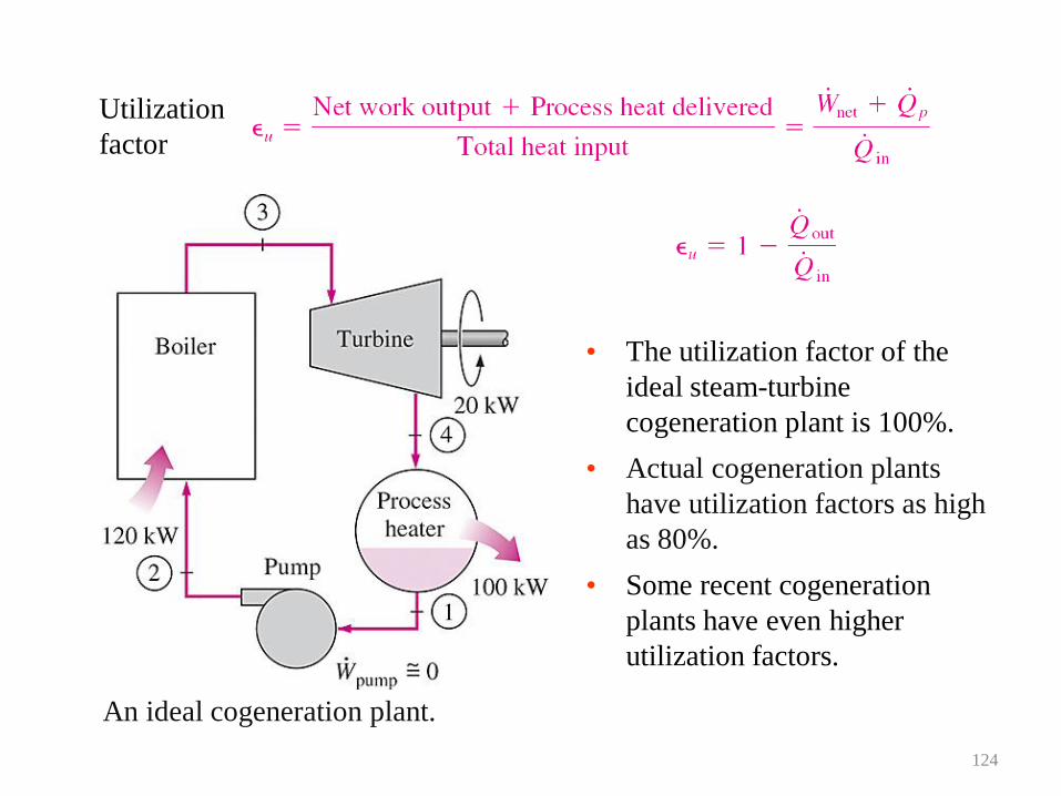
An ideal cogeneration plant.
Utilization
factor
• The utilization factor of the
ideal steam-turbine
cogeneration plant is 100%.
• Actual cogeneration plants
have utilization factors as high
as 80%.
• Some recent cogeneration
plants have even higher
utilization factors.
124
COMBINED GAS–VAPOR POWER CYCLES
• The continued quest for higher thermal efficiencies has resulted in rather innovative
modifications to conventional power plants.
• A popular modification involves a gas power cycle topping a vapor power cycle, which is
called the combined gas–vapor cycle, or just the combined cycle.
• The combined cycle of greatest interest is the gas-turbine (Brayton) cycle topping a
steam-turbine (Rankine) cycle, which has a higher thermal efficiency than either of the
cycles executed individually.
• It makes engineering sense to take advantage of the very desirable characteristics of the
gas-turbine cycle at high temperatures and to use the high-temperature exhaust gases as
the energy source for the bottoming cycle such as a steam power cycle. The result is a
combined gas–steam cycle.
• Recent developments in gas-turbine technology have made the combined gas–steam cycle
economically very attractive.
• The combined cycle increases the efficiency without increasing the initial cost greatly.
Consequently, many new power plants operate on combined cycles, and many more
existing steam- or gas-turbine plants are being converted to combined-cycle power plants.
• Thermal efficiencies over 50% are reported.
125
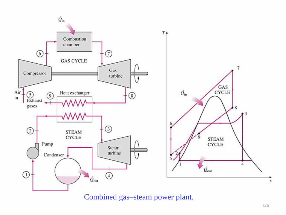
Combined gas–steam power plant.126
UNIT-V
POWER PLANT ECONOMICS AND
ENVIRONMENTAL
CONSIDERATIONS
127
The function of a power station is to deliver
power at the lowest possible cost per kilo watt
hour. This total cost is made up of fixed charges
consisting of interest on the capital, taxes,
insurance, depreciation and salary of managerial
staff, the operating expenses such as cost of
fuels, water, oil, labor, repairs and maintenance
etc.
128
Load curve:
Load curve is plot of load in kilowatts versus time usually for a
day or a year.
Load duration curve:
Load duration curve is the plot of load in kilowatts versus time
duration for which it occurs.
Maximum demand:
Maximum demand is the greatest of all demands which have
occurred during a given period of time.
Average load:
Average load is is the average load on the power station in a given
period (day/month or year)
129
Base load:
Base load is the minimum load over a given period of time.
Connected load:
Connected load of a system is the sum of the continuous ratings of the load
consuming apparatus connected to the system.
Peak load:
Peak load is the maximum load consumed or produced by a unit or group of
units in a stated period of time. It may be the maximum instantaneous load
or the maximum average load over a designated interval of time.
Demand factor:
Demand factor is the ratio of maximum demand to the connected load of a
consumer.
130
Diversity factor:
Diversity factor is the ratio of sum of individual maximum demands to the
combined maximum demand on power stations
Load factor:
Load factor is the ratio of average load during a specified period to the
maximum load occurring during the period.
Load factor = Average Load / Maximum demand
Station load factor:
Station load factor is the ratio of net power generated to the net maximum
demand on a power station.
Plant factor:
Plant factor is the ratio of the average load on the plant for the period of
time considered, to the aggregate rating of the generating equipment
installed in the plant.
131
Capacity factor:
Capacity factor is the ratio of the average load on the machine
for a period of time considered, to the rating of the machine.
Demand factor:
Demand factor is the ratio of maximum demand of system or
part of system, to the total connected load of the system, or
part of system, under consideration.
132
CONCLUSION
EVERY PART OF THE PLANT IS PLAYS AN IMPORTANT ROLE FOR THE
PLANT. WITHOUT THIS COMPONENTS THE PLANT OR BOILER CANT
EVEN RUN AND IF RUNS ALSO THEN THERE IS A100% CHANCE OF A
TRIPPING OF PLANT AND BECAUSE OF WHICH VERY HUGE AMOUNT
OF LOSSES IN MAN, MONEY AND TIME OCCURES.
133