Embed Size (px)
Citation preview
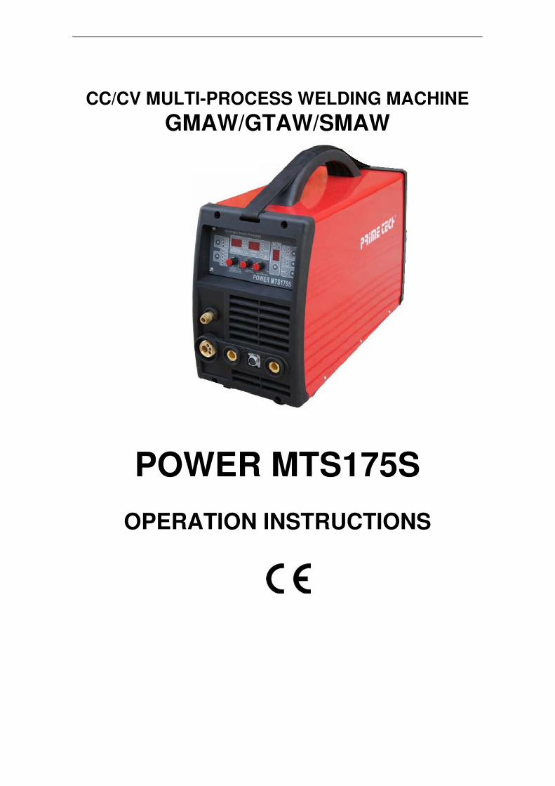
CC/CV MULTI-PROCESS WELDING MACHINE
GMAW/GTAW/SMAW
POWER MTS175S
OPERATION INSTRUCTIONS
2
Thank you for selecting the POWER MTS175S Compact MIG Welder. We want you to take pride in
operating our POWER MTS175S as much pride as we have taken in making this product for you.
PLEASE EXAMINE CARTON AND EQUIPMENT FOR DAMAGE IMMEDIATELY
When this equipment is shipped, title passes to the purchaser upon receipt from the courier.
Consequently all claims for material damaged in shipment must be made by purchaser against the
transportation company used.
Please record your equipment identification below for future reference. This information can be found ondata
plate at rear of machine.
Product POWER MTS175S Serial
No. ___________________________________
Date of Purchase _____________________________
Where Purchased _____________________________
Whenever you request replacement parts or information on this equipment please always supply
information you have recorded above
Please read this operator manual completely before attempting to use this equipment. Pay
particular attention to the safety instructions we have provided you for your protection
The level of seriousness to be applied to each section is explained below
WARNING
This statement appears where the information must be followed exactly to avoid serious personal injury.
CAUTION
This statement appears where the information must be following to avoid a minor personal injury or damage
to this equipment.
3
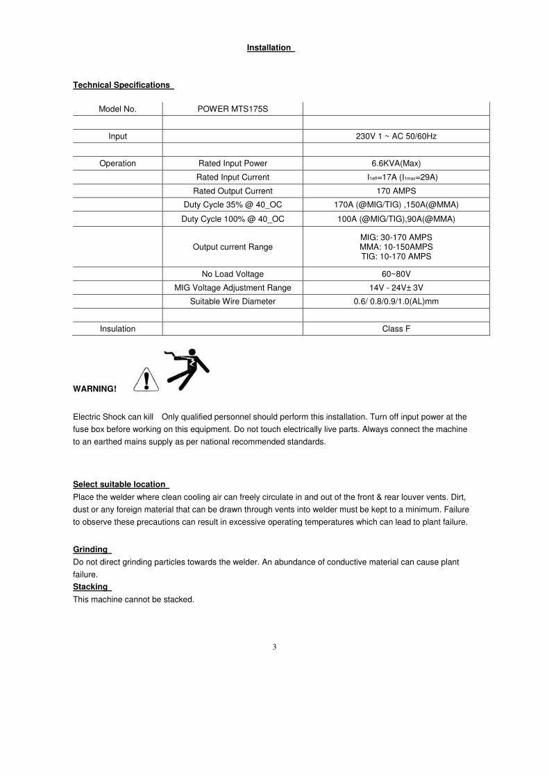
Installation
Technical Specifications
Model No. POWER MTS175S
Input 230V 1 ~ AC 50/60Hz
Operation Rated Input Power 6.6KVA(Max)
Rated Input Current I1eff=17A (I1max=29A)
Rated Output Current 170 AMPS
Duty Cycle 35% @ 40_OC 170A (@MIG/TIG) ,150A(@MMA)
Duty Cycle 100% @ 40_OC 100A (@MIG/TIG),90A(@MMA)
Output current Range MIG: 30-170 AMPS MMA: 10-150AMPS TIG: 10-170 AMPS
No Load Voltage 60~80V
MIG Voltage Adjustment Range 14V - 24V± 3V
Suitable Wire Diameter 0.6/ 0.8/0.9/1.0(AL)mm
Insulation Class F
WARNING!
Electric Shock can kill Only qualified personnel should perform this installation. Turn off input power at the
fuse box before working on this equipment. Do not touch electrically live parts. Always connect the machine
to an earthed mains supply as per national recommended standards.
Select suitable location
Place the welder where clean cooling air can freely circulate in and out of the front & rear louver vents. Dirt,
dust or any foreign material that can be drawn through vents into welder must be kept to a minimum. Failure
to observe these precautions can result in excessive operating temperatures which can lead to plant failure.
Grinding
Do not direct grinding particles towards the welder. An abundance of conductive material can cause plant
failure.
Stacking
This machine cannot be stacked.
4
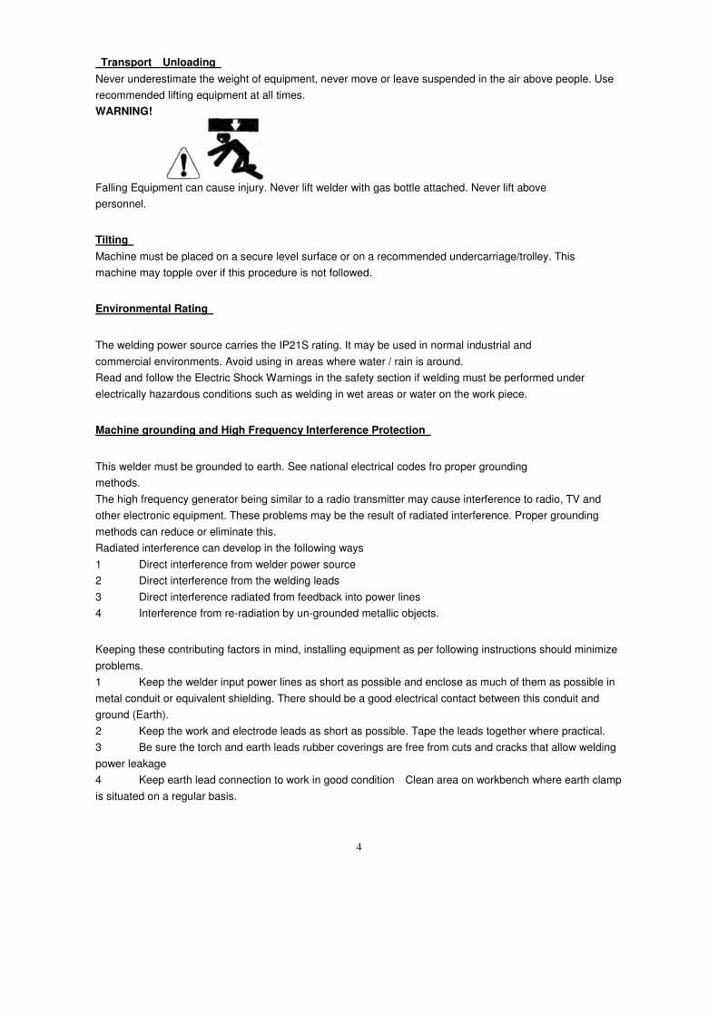
Transport Unloading
Never underestimate the weight of equipment, never move or leave suspended in the air above people. Use
recommended lifting equipment at all times.
WARNING!
Falling Equipment can cause injury. Never lift welder with gas bottle attached. Never lift above
personnel.
Tilting
Machine must be placed on a secure level surface or on a recommended undercarriage/trolley. This
machine may topple over if this procedure is not followed.
Environmental Rating
The welding power source carries the IP21S rating. It may be used in normal industrial and
commercial environments. Avoid using in areas where water / rain is around.
Read and follow the Electric Shock Warnings in the safety section if welding must be performed under
electrically hazardous conditions such as welding in wet areas or water on the work piece.
Machine grounding and High Frequency Interference Protection
This welder must be grounded to earth. See national electrical codes fro proper grounding
methods.
The high frequency generator being similar to a radio transmitter may cause interference to radio, TV and
other electronic equipment. These problems may be the result of radiated interference. Proper grounding
methods can reduce or eliminate this.
Radiated interference can develop in the following ways
1 Direct interference from welder power source
2 Direct interference from the welding leads
3 Direct interference radiated from feedback into power lines
4 Interference from re-radiation by un-grounded metallic objects.
Keeping these contributing factors in mind, installing equipment as per following instructions should minimize
problems.
1 Keep the welder input power lines as short as possible and enclose as much of them as possible in
metal conduit or equivalent shielding. There should be a good electrical contact between this conduit and
ground (Earth).
2 Keep the work and electrode leads as short as possible. Tape the leads together where practical.
3 Be sure the torch and earth leads rubber coverings are free from cuts and cracks that allow welding
power leakage
4 Keep earth lead connection to work in good condition Clean area on workbench where earth clamp
is situated on a regular basis.
5
Input Connections
Make sure the voltage, phase and frequency of input power is as specified on machine rating plate located
at rear of machine.
Have a qualified electrician provide suitable input power as per national electrical codes. Make sure machine
is earthed / grounded.
Make sure fuse or circuit breaker is correct rating for machine. Using fuses or circuit breakers smaller
than recommended will result in nuisance shut off from welder inrush currents even if welding at low
amperages.
On multiple voltage input welders, be sure the machine is connected as per the instructions for the voltage
being supplied to welder Failure to follow these instructions can cause immediate failure within the welder
and void machines warranty.
WARNING!
ELECTRIC SHOCK CAN KILL
Turn the input power OFF at the mains switch & fuse box before working on this equipment.
Have a qualified electrician install & service this equipment.
Allow machine to sit for 5 minutes minimum to allow the power capacitors to discharge before
working inside this equipment. Do not touch electrically live parts
The POWER MTS175S Inverter Welder requires a 230V 50/60Hz 29amp power supply.
It comes with a 3 metre mains cable attached.
Connect wires according to national coding.
Brown wire - Live
Blue wire - Neutral
Green/Yellow Wire - Earth (Ground)
Connecting to a mains electrical supply
THIS MACHINE IS OF AN INDUSTRIAL SPECIFICATION AND CAN CONNECT
WITH 16A SOCKET.
Connecting to an Engine Driven Generator If connecting this machine to an engine driven generator please ensure
the following Minimum Generator KVA Output - 7.5 KVA
continuous Generator to be fitted with AVR (automatic voltage regulation)
DO NOT USE ON A GENERATOR WITHOUT AVR Connecting to a generator
without the above minimum requirements will invalidate your warranty.
6
Product Description
The MTS175S is a member of our field acclaimed family of welding products.
This kind of welding power Model MTS175S is taken foreign advanced technology to develop and
manufacture the new generation inverter integrated controlling Semi-auto MIG/MAGMMA Arc welding
machine.It makes use of the import key parts such as Siemens IGBT module of Germany,alloy magnetic
core and the resume diode module of America. It has the perfect performance of high quality ,good
reliability, quick speed of welding current, steady welding process,low splash and good welding form .
Anyway,It becomes the welding very easy.
Recommended Processes
The POWER MTS175S is recommended for the MIG welding processes within its output capacity of
170 Amps DC
Equipment Limitations
The POWER MTS175S is protected from overloads beyond the output ratings and duty cycle as per
machine specifications with thermostat protection of the output coils and rectifiers.
Welding Capability Duty Cycle
The POWER MTS175S is rated at 170 Amps(MIG) at 35% duty cycle on a ten minute basis. If the
duty cycle is exceeded a thermal protector will shut machine off until the machine cools.
The POWER MTS175S is rated at 150 Amps(MMA) at 35% duty cycle on a ten minute basis. If the duty
cycle is exceeded a thermal protector will shut machine off until the machine cools.
The POWER MTS175S is rated at 170 Amps(TIG) at 35% duty cycle on a ten minute basis. If the duty
cycle is exceeded a thermal protector will shut machine off until the machine cools.
Controls and Settings
Front Panel
7
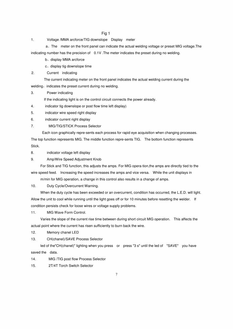
Fig 1
1. Voltage /MMA arcforce/TIG downslope Display meter
a、The meter on the front panel can indicate the actual welding voltage or preset MIG voltage.The
indicating number has the precision of 0.1V .The meter indicates the preset during no welding.
b、display MMA arcforce
c、display tig downslope time
2. Current indicating
The current indicating meter on the front panel indicates the actual welding current during the
welding,indicates the preset current during no welding.
3. Power indicating
If the indicating light is on the control circuit connects the power already.
4. indicator tig downslope or post flow time left display)
5. indicator wire speed right display
6. indicator current right display
7. MIG/TIG/STICK Process Selector
Each icon graphically repre-sents each process for rapid eye acquisition when changing processes.
The top function represents MIG. The middle function repre-sents TIG. The bottom function represents
Stick.
8. indicator voltage left display
9. Amp/Wire Speed Adjustment Knob
For Stick and TIG function, this adjusts the amps. For MIG opera-tion,the amps are directly tied to the
wire speed feed. Increasing the speed increases the amps and vice versa. While the unit displays in
m/min for MIG operation, a change in this control also results in a change of amps.
10. Duty Cycle/Overcurrent Warning.
When the duty cycle has been exceeded or an overcurrent, condition has occurred, the L.E.D. will light.
Allow the unit to cool while running until the light goes off or for 10 minutes before resetting the welder. If
condition persists check for loose wires or voltage supply problems.
11. MIG Wave Form Control.
Varies the slope of the current rise time between during short circuit MIG operation. This affects the
actual point where the current has risen sufficiently to burn back the wire.
12. Memory chanel LED
13. CH(chanel)/SAVE Process Selector
led of the"CH(chanel)" lighting when you press or press "3 s" until the led of "SAVE" you have
saved the data.
14. MIG /TIG post flow Process Selector
15. 2T/4T Torch Switch Selector
8
The torch trig-ger function is designed to operate for both MIG and TIG functions. To operate in 2T
mode, the trigger on either the MIG or TIG torch should be simply held down. The 4T function operates as a
torch “latch” in MIG mode that locks the MIG torch on without needing to hold the trigger. To operate 4T in
the MIG mode, simply press the torch trigger and hold it down until the arc starts. To lock it on, release the
trigger and weld without hold-ing the trigger down. To stop, the trigger must be pressed again, and then
released after 1-2 seconds. The 4T function in TIG mode acts sim-ilarly, but in conjunction with the down
slope timer. As the torch trigger is pressed for the second time, the trigger should be held in until the
downslope timer completes its cycle. The the trigger may then be released to end the arc. Releasing before
the down slope is fin-ished will terminate the arc immediately.
16. MIG Volt/TIG Down Slope/ MMA Arc Force Control/MIG TIG post flow.
In each mode, the function of the control changes. In the MIG mode, the control is used to adjust the
arc voltage. While in TIG mode, the it functions to adjust the down slope of the arc current . In Stick mode,
the control is used to vary the automatic arc force current re-sponse. When used for stick welding the arc
force is also known as “dig”. When welding in stick mode, the current is increased as the volts fall off due to a
short arc length. This helps maintain the arc by providing more watt-age.
17. Wire Alloy Selector.
Select your wire type according to the basic categories of Fe (Steel), Ss (Stainless Steel) or Al
(Aluminum). This input must be made to properly use the Synergic function to automatically adjust the Volts
needed to weld at the selected wire speed.
18. Wire Diameter/ALT selector:
Select your wire diameter according of the type wire you are using. Selecting the correct wire diameter is
critical to optimum Synergic function of the welder, automatically compensating the voltage while the wire
speed is adjusted. For alternate full manual control of the welder to function in “normal” mig mode, select ALT.
This will allow for full, independent control of MIG wire speed and voltage.
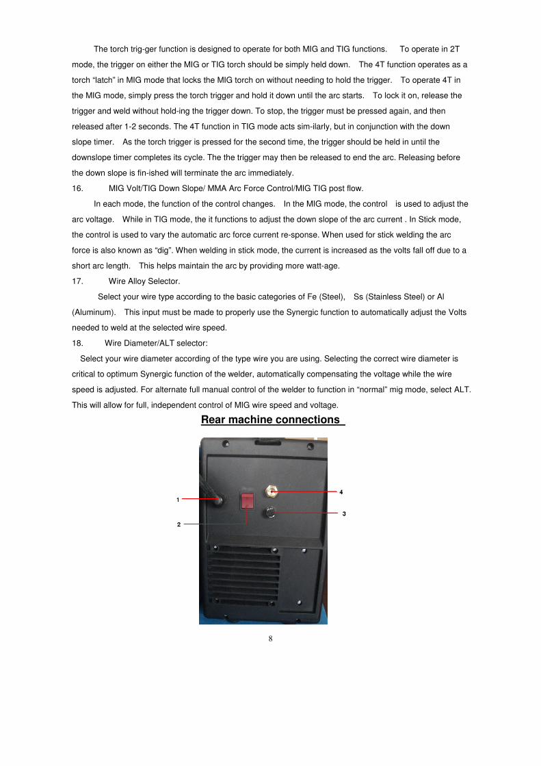
Rear machine connections
9
Fig2
1 Mains input cable (240V AC input )
Fit required plug as per your electrical installation
2 On/Off Switch
3 Fuse Holder
5A fuse for wire speed
4 Gas input connector
Connect input gas hose ensuring connection is tight
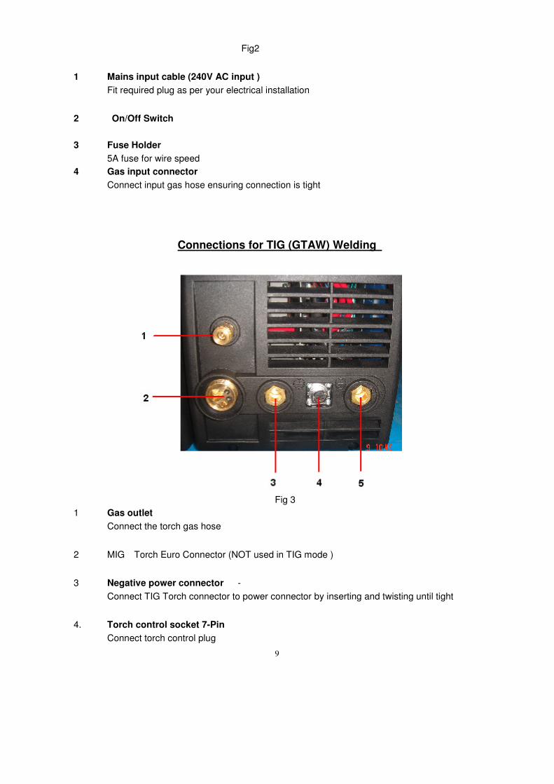
Connections for TIG (GTAW) Welding
Fig 3
1 Gas outlet
Connect the torch gas hose
2 MIG Torch Euro Connector (NOT used in TIG mode )
3 Negative power connector -
Connect TIG Torch connector to power connector by inserting and twisting until tight
4. Torch control socket 7-Pin
Connect torch control plug
10
or Remote Foot Pedal connection.
Disconnect TIG Torch switch plug from torch control socket and connect plug from foot
pedal
5. Positive power connector +
Connect the earth lead to by inserting and twisting until tight and the earth clamp to
work/bench
Connect the gas input hose to gas regulator and use 'Pure Argon' Gas, available from local
suppliers. Set gas flow/pressure to 8-12 LPM.
Make sure gas bottle is secured to avoid injury.
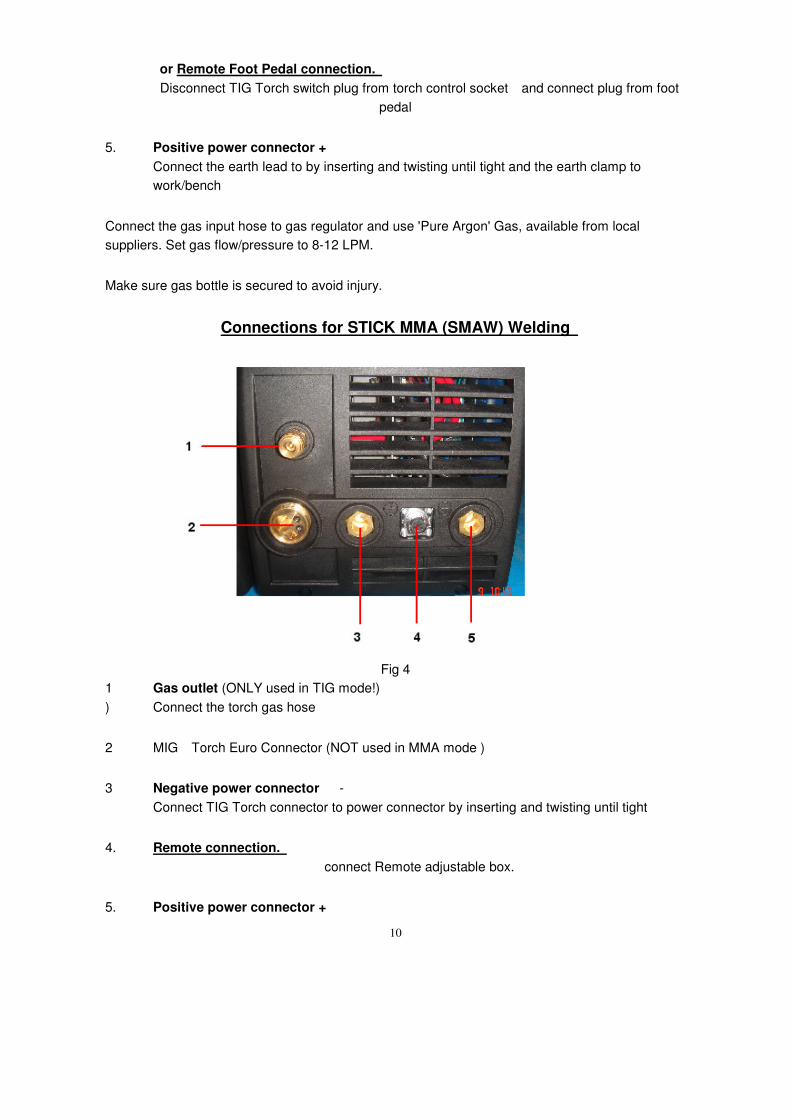
Connections for STICK MMA (SMAW) Welding
Fig 4
1 Gas outlet (ONLY used in TIG mode!)
) Connect the torch gas hose
2 MIG Torch Euro Connector (NOT used in MMA mode )
3 Negative power connector -
Connect TIG Torch connector to power connector by inserting and twisting until tight
4. Remote connection.
connect Remote adjustable box.
5. Positive power connector +
11
Connect the earth lead to by inserting and twisting until tight and the earth clamp to
work/bench
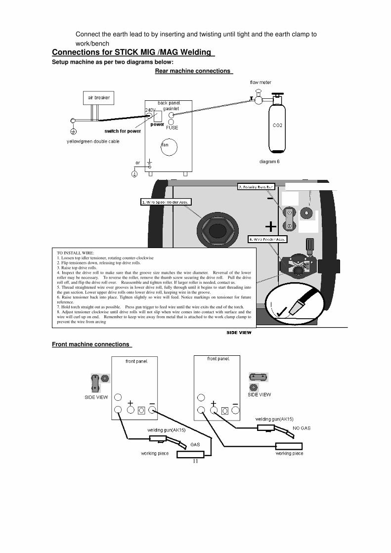
Connections for STICK MIG /MAG Welding
Setup machine as per two diagrams below:
Rear machine connections
Front machine connections
TO INSTALL WIRE:
1. Loosen top idler tensioner, rotating counter-clockwise
2. Flip tensioners down, releasing top drive rolls.
3. Raise top drive rolls.
4. Inspect the drive roll to make sure that the groove size matches the wire diameter. Reversal of the lower
roller may be necessary. To reverse the roller, remove the thumb screw securing the drive roll. Pull the drive
roll off, and flip the drive roll over. Reassemble and tighten roller. If larger roller is needed, contact us.
5. Thread straightened wire over grooves in lower drive roll, fully through until it begins to start threading into
the gun section. Lower upper drive rolls onto lower drive roll, keeping wire in the groove.
6. Raise tensioner back into place. Tighten slightly so wire will feed. Notice markings on tensioner for future
reference.
7. Hold torch straight out as possible. Press gun trigger to feed wire until the wire exits the end of the torch.
8. Adjust tensioner clockwise until drive rolls will not slip when wire comes into contact with surface and the
wire will curl up on end. Remember to keep wire away from metal that is attached to the work clamp clamp to
prevent the wire from arcing
12
Connect Euro type MIG torch to euro torch connector
To avoid shock keep the MIG torch in good condition and replace if any of the insulation is damaged.
Connect the earth lead (negative - ) to work/bench.
Connect the gas input hose to gas regulator, Set gas flow/pressure to 10-14 LPM, in drafty or open
areas a higher flow may be required to stop porosity of weld.
Make sure gas bottle is secured machine securely to avoid injury.
Operation
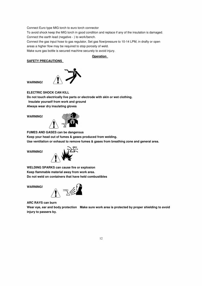
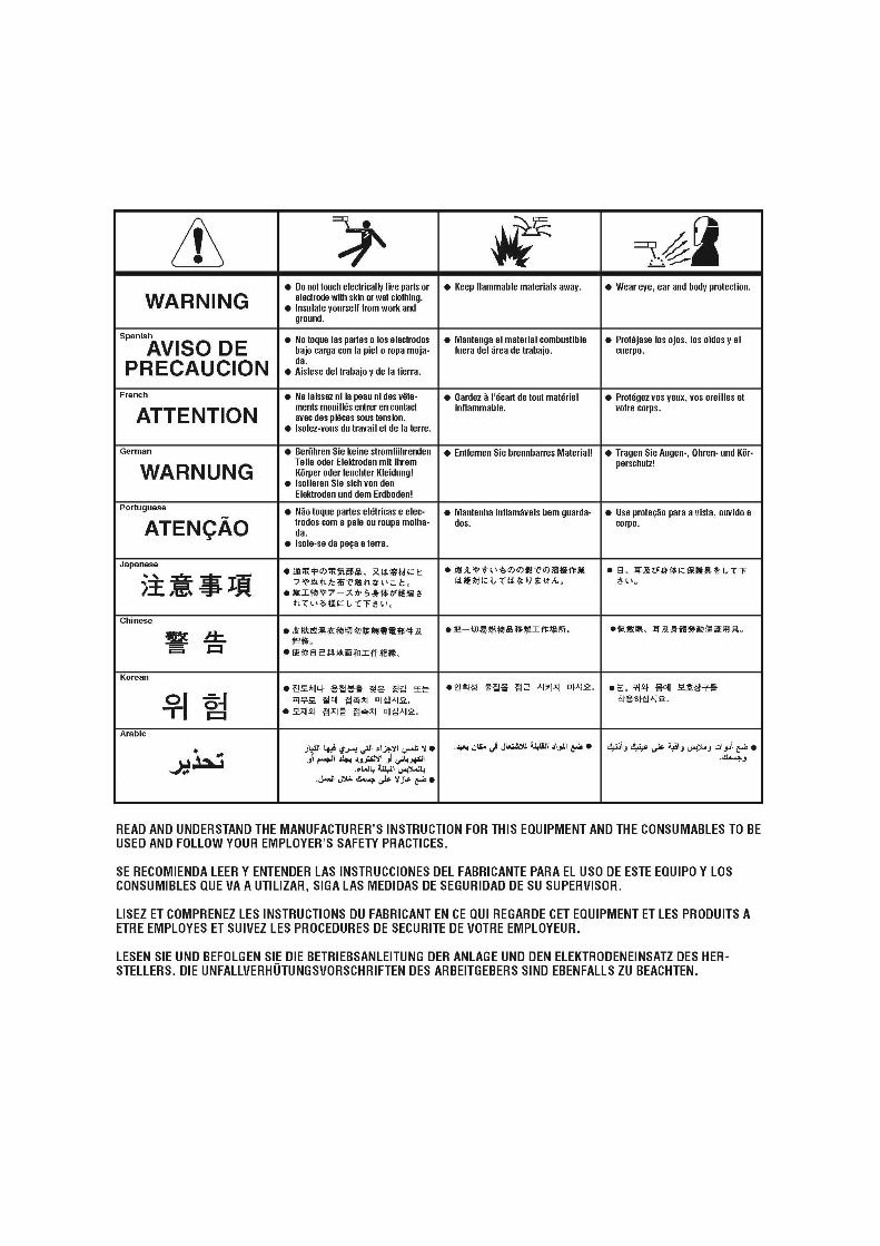
SAFETY PRECAUTIONS
WARNING!
ELECTRIC SHOCK CAN KILL
Do not touch electrically live parts or electrode with skin or wet clothing.
Insulate yourself from work and ground
Always wear dry insulating gloves
WARNING!
FUMES AND GASES can be dangerous
Keep your head out of fumes & gases produced from welding.
Use ventilation or exhaust to remove fumes & gases from breathing zone and general area.
WARNING!
WELDING SPARKS can cause fire or explosion
Keep flammable material away from work area.
Do not weld on containers that have held combustibles
WARNING!
ARC RAYS can burn
Wear eye, ear and body protection Make sure work area is protected by proper shielding to avoid
injury to passers by.
13
Welding in TIG mode - No remote foot pedal
1 Connect the TIG torch and earth lead to machine & work piece.
2 Set the TIG/MMA/MIG switch to TIG
3 Select 2 or 4 way torch operation
4 Connect Argon gas and set flow to approx 8-12 LPM
5 Set Gas post flow to 10 Seconds
6 Adjust current to desired welding current
7 Press the TIG torch switch to start welding
Welding in TIG mode - with Remote foot pedal
1 Connect the TIG Torch to machine, connect earth lead to machine & work piece.
2 Connect remote foot pedal to machine
3 Set the TIG/MMA/MIG switch to TIG
4 Select 2 way torch operation
5 Connect Argon gas and set flow to approx 8-12 LPM
6 Set Gas post flow to 5 Seconds
7 Press the foot pedal to start welding.
Note: When welding with remote foot pedal
Pre-set amperage in LED display will show what the maximum amperage foot pedal will go to (what
amperage control knob is set to), upon welding it will show actual welding amperage.
Upon pressing of foot pedal welding arc will start, if you find it hard to start arc push pedal down a bit further
to aid starting.
The benefits of welding with remote foot pedal is greater control of amount of heat going into work especially
beneficial on alloys as these absorb the heat much quicker than steel. Press pedal fully to start weld, upon
weld pool formation you can slightly release the pedal to decrease amperage to sustain perfect weld pool and
increase again as required to sustain weld characteristics.
The foot pedal adjusts from Start (min) current to Max current set on base current knob on front of machine
as shown in LED before welding.
Welding in STICK MMA (SMAW) Mode - no Remote foot pedal
1 Fit MMA electrode holder to machine
2 Fit earth lead to machine and to work piece
3 Select MMA on MMA/TIG/MIG switch
4 Place electrode in holder
5 Select desired welding current
6 Select desired Arc Force
7 Strike arc and weld
14
Welding in STICK MMA (SMAW) Mode - with Remote foot pedal
1 Fit MMA electrode holder to machine
2 Fit earth lead to machine and to work piece
3 Select MMA on MMA/TIG/MIG switch
4 Place electrode in holder
5 Select desired Arc Force
6 Connect remote adjustable boxl to machine
7 Select desired welding current
8 Strike arc and weld
Welding in MIG /MAG Mode
Synergic vs. Manual Setup and Operation
How Synergic MIG operates:
The Synergic function of the MIG (175S) component allows the user to only need to use the wire feed
speed control to make the unit operate. The welder is programmed to automatically adjust the voltage
based off the users input of wire diameter, and filler metal type when the wire speed is increased or
decreased by turning the wire speed adjustment knob. While in the Synergic mode, the user can make
manual adjustment to “fine tune” the voltage if he chooses by turning the voltage up or down after adjusting
the wire feed speed. If the wire speed is readjusted after manual adjustment to voltage is made, the unit
defaults to the synergic mode again, and voltage is once again adjusted automatically. The welder may be
used in full Manual mode, with independent control of the wire feed speed by simply selecting ALT on the
wire diameter selector. Settings will not be saved when the unit cycles off and back on and will default to
factory settings. If stepping away briefly it is best to keep the unit on, or the settings will not remember the last
settings if it is turned off.
How to setup the Synergic and Manual functions:
1. Turn the machine on. Wait for it to go through the power up cycle.
2. Select the MIG icon with the Process Selector button.
3. Select the wire diameter of the wire being used. Selecting ALT defaults unit to full manual mode.
Aluminum will default to .040"(1.0) & ALT. so that the wire will not jam or birds nest while feeding.
15
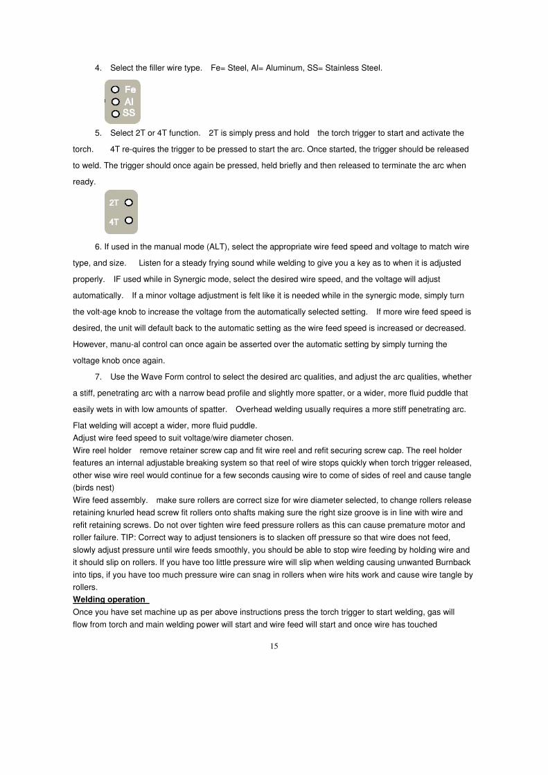
4. Select the filler wire type. Fe= Steel, Al= Aluminum, SS= Stainless Steel.
5. Select 2T or 4T function. 2T is simply press and hold the torch trigger to start and activate the
torch. 4T re-quires the trigger to be pressed to start the arc. Once started, the trigger should be released
to weld. The trigger should once again be pressed, held briefly and then released to terminate the arc when
ready.
6. If used in the manual mode (ALT), select the appropriate wire feed speed and voltage to match wire
type, and size. Listen for a steady frying sound while welding to give you a key as to when it is adjusted
properly. IF used while in Synergic mode, select the desired wire speed, and the voltage will adjust
automatically. If a minor voltage adjustment is felt like it is needed while in the synergic mode, simply turn
the volt-age knob to increase the voltage from the automatically selected setting. If more wire feed speed is
desired, the unit will default back to the automatic setting as the wire feed speed is increased or decreased.
However, manu-al control can once again be asserted over the automatic setting by simply turning the
voltage knob once again.
7. Use the Wave Form control to select the desired arc qualities, and adjust the arc qualities, whether
a stiff, penetrating arc with a narrow bead profile and slightly more spatter, or a wider, more fluid puddle that
easily wets in with low amounts of spatter. Overhead welding usually requires a more stiff penetrating arc.
Flat welding will accept a wider, more fluid puddle.
Adjust wire feed speed to suit voltage/wire diameter chosen.
Wire reel holder remove retainer screw cap and fit wire reel and refit securing screw cap. The reel holder
features an internal adjustable breaking system so that reel of wire stops quickly when torch trigger released,
other wise wire reel would continue for a few seconds causing wire to come of sides of reel and cause tangle
(birds nest)
Wire feed assembly. make sure rollers are correct size for wire diameter selected, to change rollers release
retaining knurled head screw fit rollers onto shafts making sure the right size groove is in line with wire and
refit retaining screws. Do not over tighten wire feed pressure rollers as this can cause premature motor and
roller failure. TIP: Correct way to adjust tensioners is to slacken off pressure so that wire does not feed,
slowly adjust pressure until wire feeds smoothly, you should be able to stop wire feeding by holding wire and
it should slip on rollers. If you have too little pressure wire will slip when welding causing unwanted Burnback
into tips, if you have too much pressure wire can snag in rollers when wire hits work and cause wire tangle by
rollers.
Welding operation
Once you have set machine up as per above instructions press the torch trigger to start welding, gas will
flow from torch and main welding power will start and wire feed will start and once wire has touched
16
workpiece welding will start, to stop welding release torch trigger.
Adjust wire feed speed to give desired weld characteristics
Less wire = Dip transfer welding
More wire = Spray transfer welding
TIP: Inside wire feed lid is chart with approximate recommended welding power settings required for
various sizes of material. Chart also shown below
Maintenance Routine and periodic maintenance
WARNING!
ELECTRIC SHOCK CAN KILL
Turn the input power OFF at the mains switch & fuse box before working on this equipment.
Have a qualified electrician install & service this equipment.
Allow machine to sit for 5 minutes minimum to allow the power capacitors to discharge before
working inside this equipment.
Do not touch electrically live parts
1.Periodically remove the side/top panels of machine and clean out machine with a low
pressure dry air line paying particular attention to PC Boards, Fan blades.
2.Inspect input and output cables & hoses for fraying, cuts & bare spots
3.Keep tig torch and cables in good condition
4.Clean air vents to ensure proper air flow and cooling
5.The fan motor has sealed bearings which requires no maintenance
Troubleshooting
Service & repair should only be performed by welding trained personnel. Unauthorized repairs performed
on this equipment may result in danger to the technician and machine operator and will invalidate your
warranty. For your safety and to avoid electric shock, please observe all safety notes and precautions
detailed throughout this manual
The troubleshooting guide is provided to help you locate possible machine malfunctions.
Simply follow the 3 step procedure below
Step 1 Locate problem (symptom)
Look under the column labeled Problem (symptoms). This column describes possible symptoms that the
machine may exhibit. Find the listing that best describes the symptom that the machine is exhibiting
Step 2 Possible Cause
17
The second column labeled possible cause lists the obvious external possibilities that may contribute to the
machine symptom
Step 3 Recommended course of action
This column provides a course of action for the possible cause, generally it states to contact welding
for repair of machine.
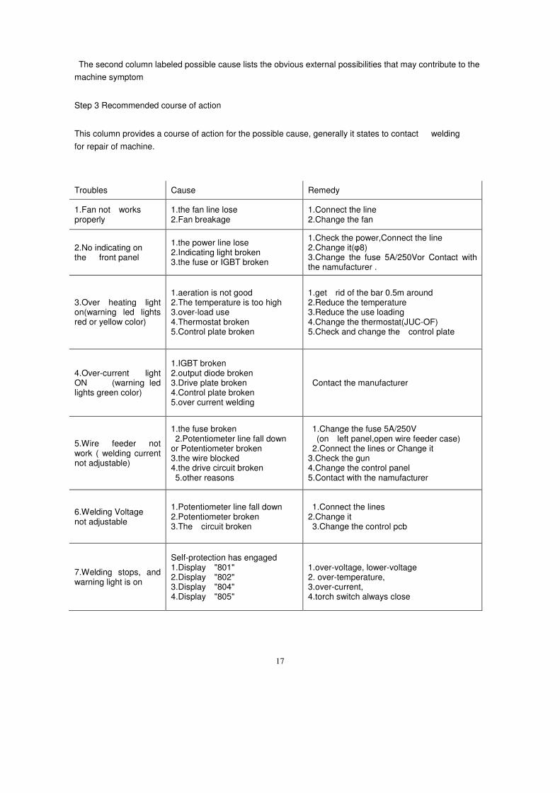
Troubles Cause Remedy
1.Fan not works properly
1.the fan line lose 2.Fan breakage
1.Connect the line 2.Change the fan
2.No indicating on the front panel
1.the power line lose 2.Indicating light broken 3.the fuse or IGBT broken
1.Check the power,Connect the line 2.Change it(φ8) 3.Change the fuse 5A/250Vor Contact with the namufacturer .
3.Over heating light on(warning led lights red or yellow color)
1.aeration is not good 2.The temperature is too high 3.over-load use 4.Thermostat broken 5.Control plate broken
1.get rid of the bar 0.5m around 2.Reduce the temperature 3.Reduce the use loading 4.Change the thermostat(JUC-OF) 5.Check and change the control plate
4.Over-current light ON (warning led lights green color)
1.IGBT broken 2.output diode broken 3.Drive plate broken 4.Control plate broken 5.over current welding
Contact the manufacturer
5.Wire feeder not work ( welding current not adjustable)
1.the fuse broken 2.Potentiometer line fall down or Potentiometer broken 3.the wire blocked 4.the drive circuit broken 5.other reasons
1.Change the fuse 5A/250V (on left panel,open wire feeder case) 2.Connect the lines or Change it 3.Check the gun 4.Change the control panel 5.Contact with the namufacturer
6.Welding Voltage not adjustable
1.Potentiometer line fall down 2.Potentiometer broken 3.The circuit broken
1.Connect the lines 2.Change it 3.Change the control pcb
7.Welding stops, and warning light is on
Self-protection has engaged 1.Display "801" 2.Display "802" 3.Display "804" 4.Display "805"
1.over-voltage, lower-voltage 2. over-temperature, 3.over-current, 4.torch switch always close
18
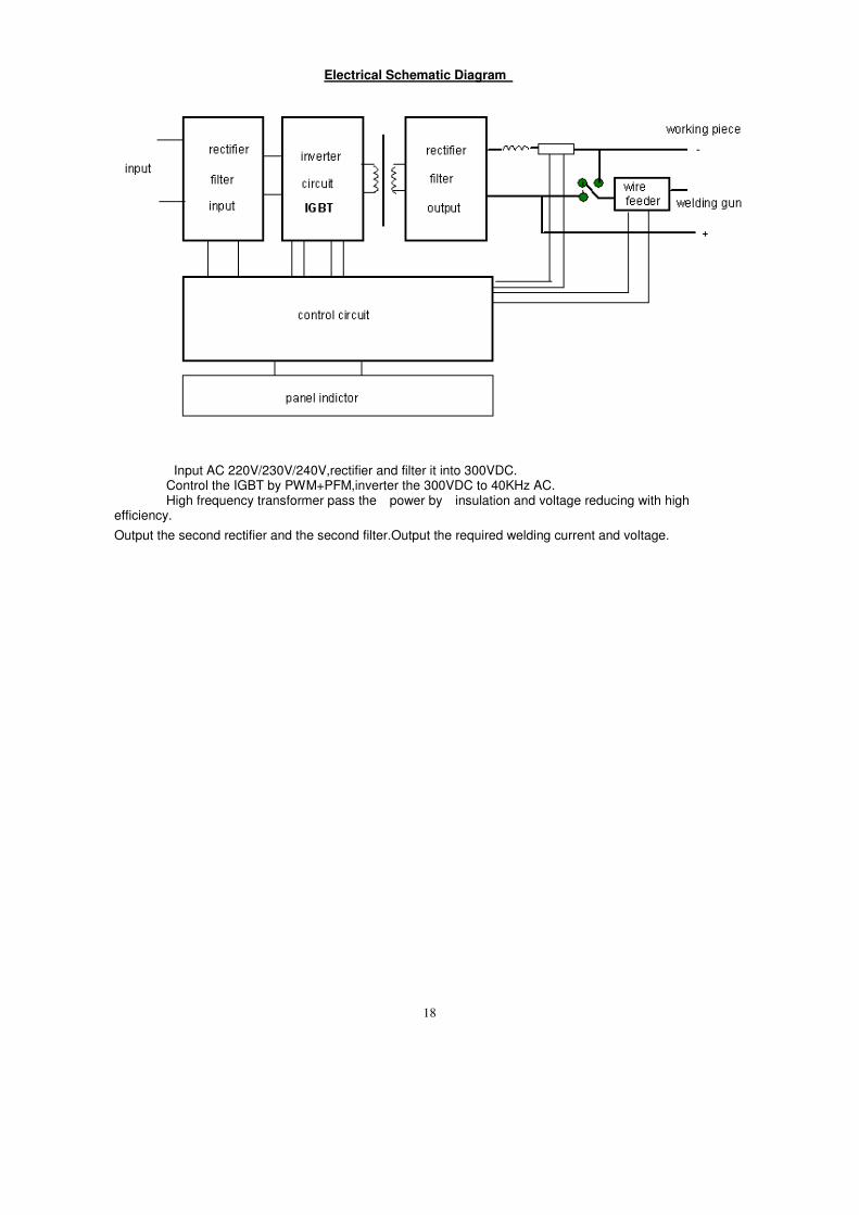
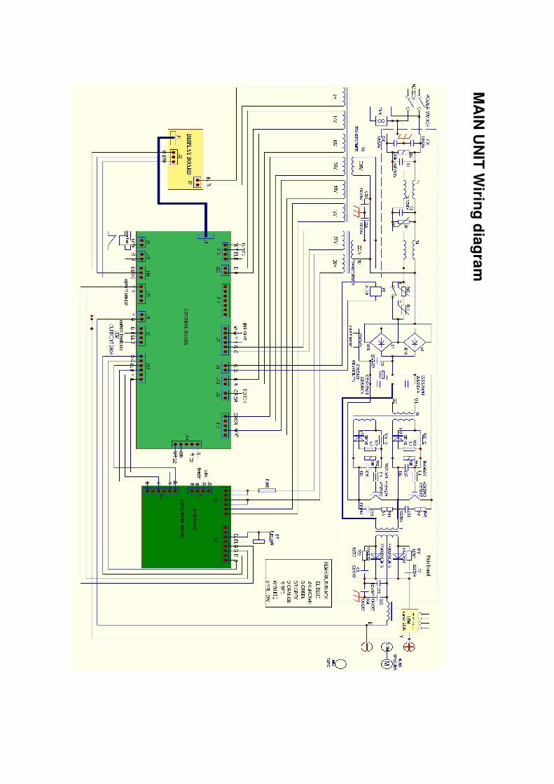
Electrical Schematic Diagram
Input AC 220V/230V/240V,rectifier and filter it into 300VDC. Control the IGBT by PWM+PFM,inverter the 300VDC to 40KHz AC. High frequency transformer pass the power by insulation and voltage reducing with high
efficiency.
Output the second rectifier and the second filter.Output the required welding current and voltage.
19
MA
IN U
NIT
Wirin
g d
iag
ram
20
21

22


![Guidelines to Gas Tungsten Arc Welding[GTAW]](https://img.pdfslide.us/doc/110x75/55cf99fe550346d033a00a2b/guidelines-to-gas-tungsten-arc-weldinggtaw.jpg)