Embed Size (px)
Citation preview
Power generation Tool and method advances for efficient manufacturing
2
48 22
13
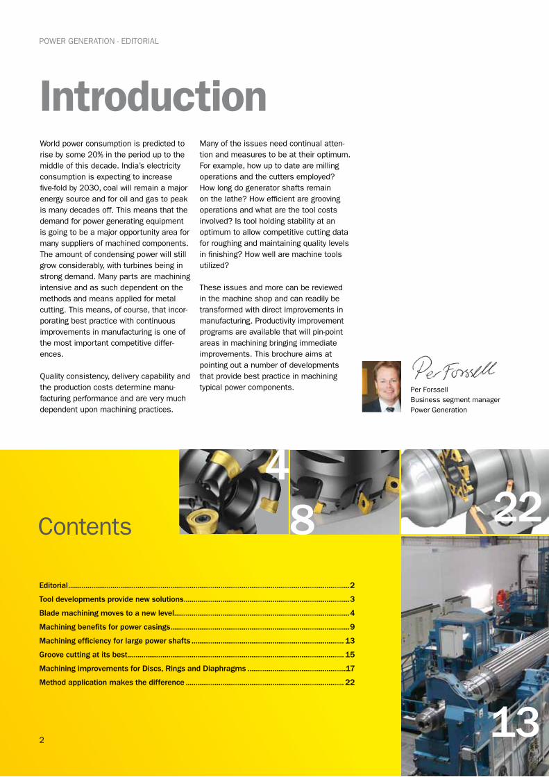
Introduction
POWER GENERATION - EDITORIAL
World power consumption is predicted to rise by some 20% in the period up to the middle of this decade. India’s electricity consumption is expecting to increase five-fold by 2030, coal will remain a major energy source and for oil and gas to peak is many decades off. This means that the demand for power generating equipment is going to be a major opportunity area for many suppliers of machined components. The amount of condensing power will still grow considerably, with turbines being in strong demand. Many parts are machining intensive and as such dependent on the methods and means applied for metal cutting. This means, of course, that incor-porating best practice with continuous improvements in manufacturing is one of the most important competitive differ-ences.
Quality consistency, delivery capability and the production costs determine manu-facturing performance and are very much dependent upon machining practices.
Many of the issues need continual atten-tion and measures to be at their optimum. For example, how up to date are milling operations and the cutters employed? How long do generator shafts remain on the lathe? How efficient are grooving operations and what are the tool costs involved? Is tool holding stability at an optimum to allow competitive cutting data for roughing and maintaining quality levels in finishing? How well are machine tools utilized?
These issues and more can be reviewed in the machine shop and can readily be transformed with direct improvements in manufacturing. Productivity improvement programs are available that will pin-point areas in machining bringing immediate improvements. This brochure aims at pointing out a number of developments that provide best practice in machining typical power components.
Editorial ..................................................................................................................................................2
Tool developments provide new solutions ......................................................................................3
Blade machining moves to a new level ...........................................................................................4
Machining benefits for power casings .............................................................................................9
Machining efficiency for large power shafts ............................................................................... 13
Groove cutting at its best ................................................................................................................ 15
Machining improvements for Discs, Rings and Diaphragms ...................................................17
Method application makes the difference .................................................................................. 22
Contents
Per ForssellBusiness segment managerPower Generation
3
22
13
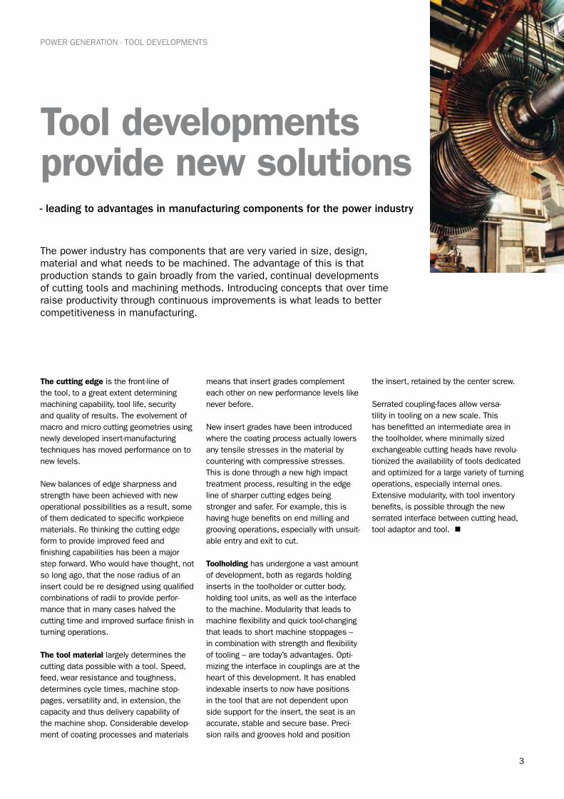
Tool developments provide new solutions
POWER GENERATION - TOOL DEVELOPMENTS
The power industry has components that are very varied in size, design, material and what needs to be machined. The advantage of this is that production stands to gain broadly from the varied, continual developments of cutting tools and machining methods. Introducing concepts that over time raise productivity through continuous improvements is what leads to better competitiveness in manufacturing.
- leading to advantages in manufacturing components for the power industry
The cutting edge is the front-line of the tool, to a great extent determining machining capability, tool life, security and quality of results. The evolvement of macro and micro cutting geometries using newly developed insert-manufacturing techniques has moved performance on to new levels.
New balances of edge sharpness and strength have been achieved with new operational possibilities as a result, some of them dedicated to specific workpiece materials. Re thinking the cutting edge form to provide improved feed and finishing capabilities has been a major step forward. Who would have thought, not so long ago, that the nose radius of an insert could be re designed using qualified combinations of radii to provide perfor-mance that in many cases halved the cutting time and improved surface finish in turning operations.
The tool material largely determines the cutting data possible with a tool. Speed, feed, wear resistance and toughness, determines cycle times, machine stop-pages, versatility and, in extension, the capacity and thus delivery capability of the machine shop. Considerable develop-ment of coating processes and materials
means that insert grades complement each other on new performance levels like never before.
New insert grades have been introduced where the coating process actually lowers any tensile stresses in the material by countering with compressive stresses. This is done through a new high impact treatment process, resulting in the edge line of sharper cutting edges being stronger and safer. For example, this is having huge benefits on end milling and grooving operations, especially with unsuit-able entry and exit to cut.
Toolholding has undergone a vast amount of development, both as regards holding inserts in the toolholder or cutter body, holding tool units, as well as the interface to the machine. Modularity that leads to machine flexibility and quick tool-changing that leads to short machine stoppages – in combination with strength and flexibility of tooling – are today’s advantages. Opti-mizing the interface in couplings are at the heart of this development. It has enabled indexable inserts to now have positions in the tool that are not dependent upon side support for the insert, the seat is an accurate, stable and secure base. Preci-sion rails and grooves hold and position
the insert, retained by the center screw.
Serrated coupling-faces allow versa-tility in tooling on a new scale. This has benefitted an intermediate area in the toolholder, where minimally sized exchangeable cutting heads have revolu-tionized the availability of tools dedicated and optimized for a large variety of turning operations, especially internal ones. Extensive modularity, with tool inventory benefits, is possible through the new serrated interface between cutting head, tool adaptor and tool. n
4
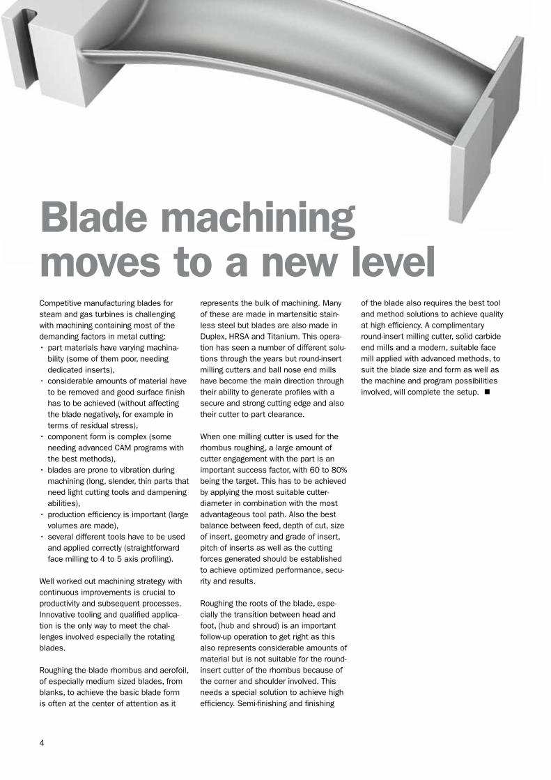
Blade machining moves to a new levelCompetitive manufacturing blades for steam and gas turbines is challenging with machining containing most of the demanding factors in metal cutting:•part materials have varying machina-
bility (some of them poor, needing dedicated inserts),
•considerable amounts of material have to be removed and good surface finish has to be achieved (without affecting the blade negatively, for example in terms of residual stress),
•component form is complex (some needing advanced CAM programs with the best methods),
•blades are prone to vibration during machining (long, slender, thin parts that need light cutting tools and dampening abilities),
•production efficiency is important (large volumes are made),
•several different tools have to be used and applied correctly (straightforward face milling to 4 to 5 axis profiling).
Well worked out machining strategy with continuous improvements is crucial to productivity and subsequent processes. Innovative tooling and qualified applica-tion is the only way to meet the chal-lenges involved especially the rotating blades.
Roughing the blade rhombus and aerofoil, of especially medium sized blades, from blanks, to achieve the basic blade form is often at the center of attention as it
represents the bulk of machining. Many of these are made in martensitic stain-less steel but blades are also made in Duplex, HRSA and Titanium. This opera-tion has seen a number of different solu-tions through the years but round-insert milling cutters and ball nose end mills have become the main direction through their ability to generate profiles with a secure and strong cutting edge and also their cutter to part clearance.
When one milling cutter is used for the rhombus roughing, a large amount of cutter engagement with the part is an important success factor, with 60 to 80% being the target. This has to be achieved by applying the most suitable cutter-diameter in combination with the most advantageous tool path. Also the best balance between feed, depth of cut, size of insert, geometry and grade of insert, pitch of inserts as well as the cutting forces generated should be established to achieve optimized performance, secu-rity and results.
Roughing the roots of the blade, espe-cially the transition between head and foot, (hub and shroud) is an important follow-up operation to get right as this also represents considerable amounts of material but is not suitable for the round-insert cutter of the rhombus because of the corner and shoulder involved. This needs a special solution to achieve high efficiency. Semi-finishing and finishing
of the blade also requires the best tool and method solutions to achieve quality at high efficiency. A complimentary round-insert milling cutter, solid carbide end mills and a modern, suitable face mill applied with advanced methods, to suit the blade size and form as well as the machine and program possibilities involved, will complete the setup. n
5
POWER GENERATION - BLADE MACHINING
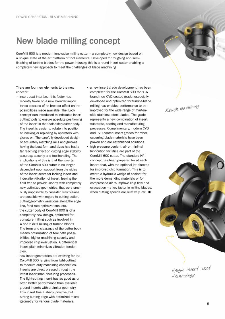
New blade milling concept
There are four new elements to the new concept:• insert seat interface; this factor has
recently taken on a new, broader impor-tance because of its broader effect on the possibilities made available. The iLock concept was introduced to indexable insert cutting tools to ensure absolute positioning of the insert in the toolholder/cutter body. The insert is easier to rotate into position at indexing or replacing by operators with gloves on. The carefully developed design of accurately matching rails and grooves having the best form and sizes has had a far reaching effect on cutting edge stability, accuracy, security and tool-handling. The implications of this is that the inserts of the CoroMill 600 cutter is no longer dependent upon support from the sides of the insert seats for locking insert and indexation/fixation of insert, leaving the field free to provide inserts with completely new optimized geometries, that were previ-ously impossible to consider. New visions are possible with regard to cutting action, cutting geometry variations along the edge line, feed rate optimizations, etc.
• the cutter body of CoroMill 600 is of a completely new design, optimized for curvature milling such as involved in 4 and 5 axis milling of turbine blades. The form and clearance of the cutter body means optimization of tool path possi-bilities, higher machining security and improved chip evacuation. A differential insert pitch minimizes vibration tenden-cies.
•new insert-geometries are evolving for the CoroMill 600 ranging from light-cutting to medium duty machining capabilities. Inserts are direct pressed through the latest insert-manufacturing processes. The light-cutting insert has as good as or often better performance than available ground inserts with a similar geometry. This insert has a sharp, positive, but strong cutting edge with optimized micro geometry for various blade materials.
•a new insert grade development has been completed for the CoroMill 600 tools. A brand new CVD coated grade, especially developed and optimized for turbine-blade milling has enabled performance to be improved for the wide range of marten-sitic stainless steel blades. The grade represents a new combination of insert substrate, coating and manufacturing processes. Complimentary, modern CVD and PVD coated insert grades for other occurring blade materials have been proven and are established solutions.
•high pressure coolant, air or minimal lubrication facilities are part of the CoroMill 600 cutter. The standard HP concept has been prepared for at each insert seat, with the optional jet directed for improved chip formation. This is to create a hydraulic wedge of coolant for the more demanding materials or for compressed air to improve chip flow and evacuation – a key factor in milling blades, when cutting speeds are relatively low. n
Rough machining
CoroMill 600 is a modern innovative milling cutter – a completely new design based on a unique state of the art platform of tool elements. Developed for roughing and semi-finishing of turbine blades for the power industry, this is a round insert cutter enabling a completely new approach to meet the challenges of blade machining
Unique insert seat technology
6
POWER GENERATION - BLADE MACHINING
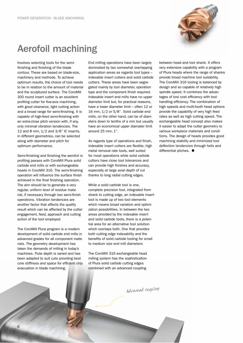
Aerofoil machining Involves selecting tools for the semi-finishing and finishing of the blade contour. These are based on blade-size, machinery and methods. To achieve optimum results, the choice of tool needs to be in relation to the amount of material and the sculptured surface. The CoroMill 300 round insert cutter is an excellent profiling cutter for five-axis machining, with good clearance, light cutting action and a broad range for semi-finishing. It is capable of high-feed semi-finishing with an extra-close pitch version with, if any, only minimal vibration tendencies. The 12 and 8 mm, 1/2 and 3/8” IC inserts, in different geometries, can be selected along with diameter and pitch for optimum performance.
Semi-finishing and finishing the aerofoil is profiling passes with CoroMill Plura solid carbide end mills or with exchangeable heads in CoroMill 316. The semi-finishing operation will influence the surface finish achieved in the final finishing operation. The aim should be to generate a very regular, uniform level of residue mate-rial, if necessary through two semi-finish operations. Vibration tendencies are another factor that affects the quality result which can be affected by the cutter engagement, feed, approach and cutting action of the tool employed.
The CoroMill Plura program is a modern development of solid carbide end mills in advanced grades for all component mate-rials. The geometry development has taken the demands of milling in today’s machines. Flute depth is varied and has been adapted to suit cuts providing best core stiffness and space for efficient chip evacuation in blade machining.
End milling operations have been largely dominated by two somewhat overlapping application areas as regards tool types – indexable insert cutters and solid carbide cutters. These areas have been segre-gated mainly by tool diameter, operation type and the component finish required. Indexable insert end mills have no upper diameter limit but, for practical reasons, have a lower diameter limit – often 12 or 16 mm, 1/2 or 5/8”. Solid carbide end mills, on the other hand, can be of diam-eters down to tenths of a mm but usually have an economical upper diamater limit around 25 mm, 1”.
As regards type of operations and finish, indexable insert cutters are flexible, high metal removal rate tools, well suited for most operations while solid carbide cutters have close tool tolerances and can provide high finishes and accuracy, especially at large axial depth of cut thanks to long radial cutting edges.
While a solid carbide tool is one, complete precision tool, integrated from shank to cutting edge, an indexable insert tool is made up of two tool elements which means broad variation and optimi-zation possibilities. In between the two areas provided by the indexable insert and solid carbide tools, there is a poten-tial area for an alternative tool solution which overlaps both. One that provides both cutting edge indexability and the benefits of solid carbide tooling for small to medium size end mill diameters
The CoroMill 316 exchangeable head milling system has the sophistication of Plura solid carbide cutting edges combined with an advanced coupling
between head and tool shank. It offers very extensive capability with a program of Plura heads where the range of shanks provide broad machine tool suitability. The CoroMill 316 tooling is balanced by design and so capable of relatively high spindle speed. It combines the advan-tages of tool cost efficiency with tool-handling efficiency. The combination of high speeds and multi-tooth head options provide the capability of very high feed rates as well as high cutting speed. The exchangeable head concept also makes it easier to adapt the cutter geometry to various workpiece materials and condi-tions. The design of heads provides good machining stability and minimized tool deflection tendencies through helix and differential pitches. n
Advanced coupling
7
POWER GENERATION - BLADE MACHINING
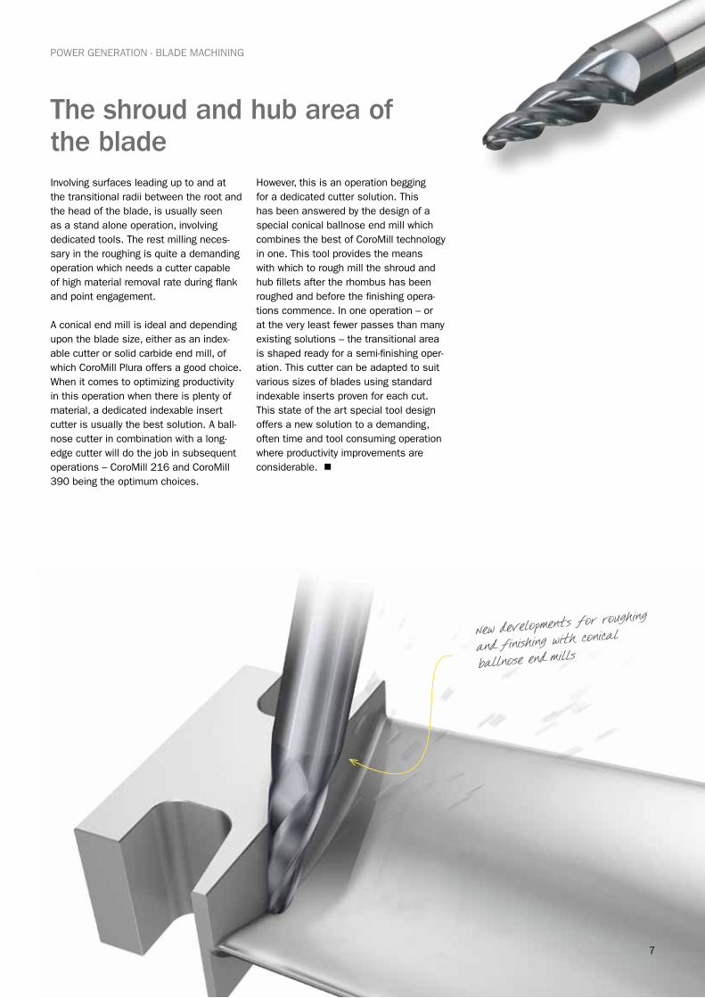
The shroud and hub area of the bladeInvolving surfaces leading up to and at the transitional radii between the root and the head of the blade, is usually seen as a stand alone operation, involving dedicated tools. The rest milling neces-sary in the roughing is quite a demanding operation which needs a cutter capable of high material removal rate during flank and point engagement.
A conical end mill is ideal and depending upon the blade size, either as an index-able cutter or solid carbide end mill, of which CoroMill Plura offers a good choice. When it comes to optimizing productivity in this operation when there is plenty of material, a dedicated indexable insert cutter is usually the best solution. A ball-nose cutter in combination with a long-edge cutter will do the job in subsequent operations – CoroMill 216 and CoroMill 390 being the optimum choices.
However, this is an operation begging for a dedicated cutter solution. This has been answered by the design of a special conical ballnose end mill which combines the best of CoroMill technology in one. This tool provides the means with which to rough mill the shroud and hub fillets after the rhombus has been roughed and before the finishing opera-tions commence. In one operation – or at the very least fewer passes than many existing solutions – the transitional area is shaped ready for a semi-finishing oper-ation. This cutter can be adapted to suit various sizes of blades using standard indexable inserts proven for each cut. This state of the art special tool design offers a new solution to a demanding, often time and tool consuming operation where productivity improvements are considerable. n
New developments for roughing
and finishing with conical
ballnose end mills
8
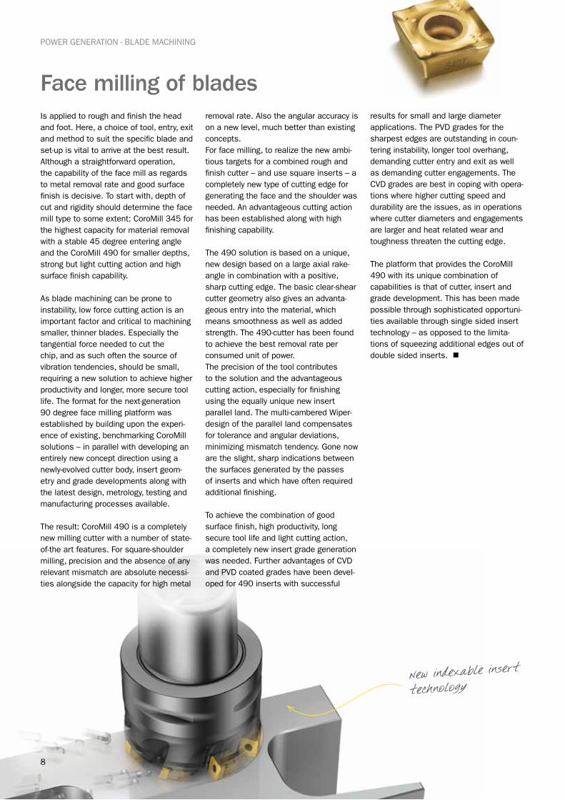
Face milling of bladesIs applied to rough and finish the head and foot. Here, a choice of tool, entry, exit and method to suit the specific blade and set-up is vital to arrive at the best result. Although a straightforward operation, the capability of the face mill as regards to metal removal rate and good surface finish is decisive. To start with, depth of cut and rigidity should determine the face mill type to some extent: CoroMill 345 for the highest capacity for material removal with a stable 45 degree entering angle and the CoroMill 490 for smaller depths, strong but light cutting action and high surface finish capability.
As blade machining can be prone to instability, low force cutting action is an important factor and critical to machining smaller, thinner blades. Especially the tangential force needed to cut the chip, and as such often the source of vibration tendencies, should be small, requiring a new solution to achieve higher productivity and longer, more secure tool life. The format for the next-generation 90 degree face milling platform was established by building upon the experi-ence of existing, benchmarking CoroMill solutions – in parallel with developing an entirely new concept direction using a newly-evolved cutter body, insert geom-etry and grade developments along with the latest design, metrology, testing and manufacturing processes available.
The result: CoroMill 490 is a completely new milling cutter with a number of state-of-the art features. For square-shoulder milling, precision and the absence of any relevant mismatch are absolute necessi-ties alongside the capacity for high metal
removal rate. Also the angular accuracy is on a new level, much better than existing concepts. For face milling, to realize the new ambi-tious targets for a combined rough and finish cutter – and use square inserts – a completely new type of cutting edge for generating the face and the shoulder was needed. An advantageous cutting action has been established along with high finishing capability.
The 490 solution is based on a unique, new design based on a large axial rake-angle in combination with a positive, sharp cutting edge. The basic clear-shear cutter geometry also gives an advanta-geous entry into the material, which means smoothness as well as added strength. The 490-cutter has been found to achieve the best removal rate per consumed unit of power. The precision of the tool contributes to the solution and the advantageous cutting action, especially for finishing using the equally unique new insert parallel land. The multi-cambered Wiper-design of the parallel land compensates for tolerance and angular deviations, minimizing mismatch tendency. Gone now are the slight, sharp indications between the surfaces generated by the passes of inserts and which have often required additional finishing.
To achieve the combination of good surface finish, high productivity, long secure tool life and light cutting action, a completely new insert grade generation was needed. Further advantages of CVD and PVD coated grades have been devel-oped for 490 inserts with successful
results for small and large diameter applications. The PVD grades for the sharpest edges are outstanding in coun-tering instability, longer tool overhang, demanding cutter entry and exit as well as demanding cutter engagements. The CVD grades are best in coping with opera-tions where higher cutting speed and durability are the issues, as in operations where cutter diameters and engagements are larger and heat related wear and toughness threaten the cutting edge.
The platform that provides the CoroMill 490 with its unique combination of capabilities is that of cutter, insert and grade development. This has been made possible through sophisticated opportuni-ties available through single sided insert technology – as opposed to the limita-tions of squeezing additional edges out of double sided inserts. n
POWER GENERATION - BLADE MACHINING
New indexable insert
technology
9
POWER GENERATION - CASINGS
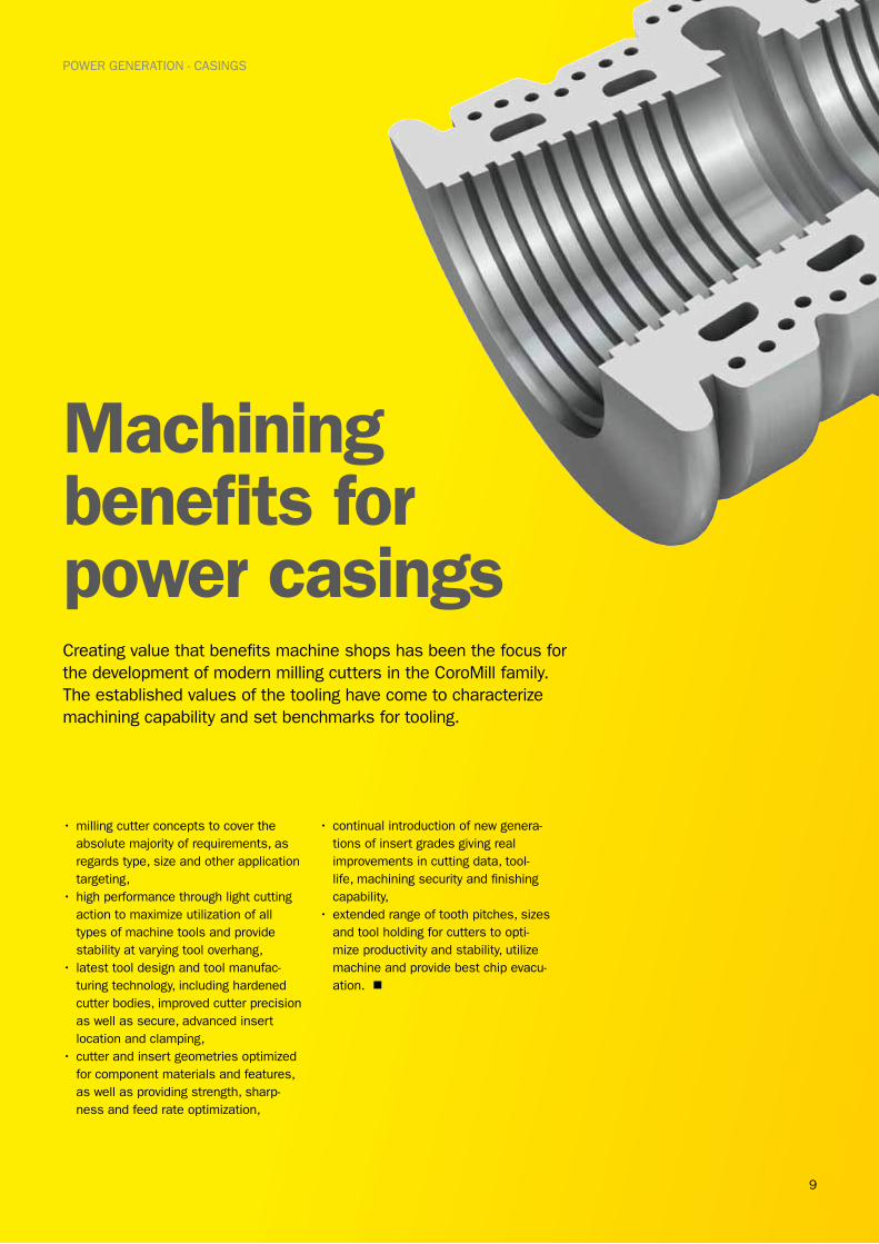
Machining benefits for power casingsCreating value that benefits machine shops has been the focus for the development of modern milling cutters in the CoroMill family. The established values of the tooling have come to characterize machining capability and set benchmarks for tooling.
•milling cutter concepts to cover the absolute majority of requirements, as regards type, size and other application targeting,
•high performance through light cutting action to maximize utilization of all types of machine tools and provide stability at varying tool overhang,
• latest tool design and tool manufac-turing technology, including hardened cutter bodies, improved cutter precision as well as secure, advanced insert location and clamping,
•cutter and insert geometries optimized for component materials and features, as well as providing strength, sharp-ness and feed rate optimization,
•continual introduction of new genera-tions of insert grades giving real improvements in cutting data, tool-life, machining security and finishing capability,
•extended range of tooth pitches, sizes and tool holding for cutters to opti-mize productivity and stability, utilize machine and provide best chip evacu-ation. n
10
POWER GENERATION - CASINGS
Good face milling performance is crucial to achieve efficient production. Milling the huge casings and housings that are part of power equipment is an area where best practice machining makes a prominent difference to through put and manufacturing costs.
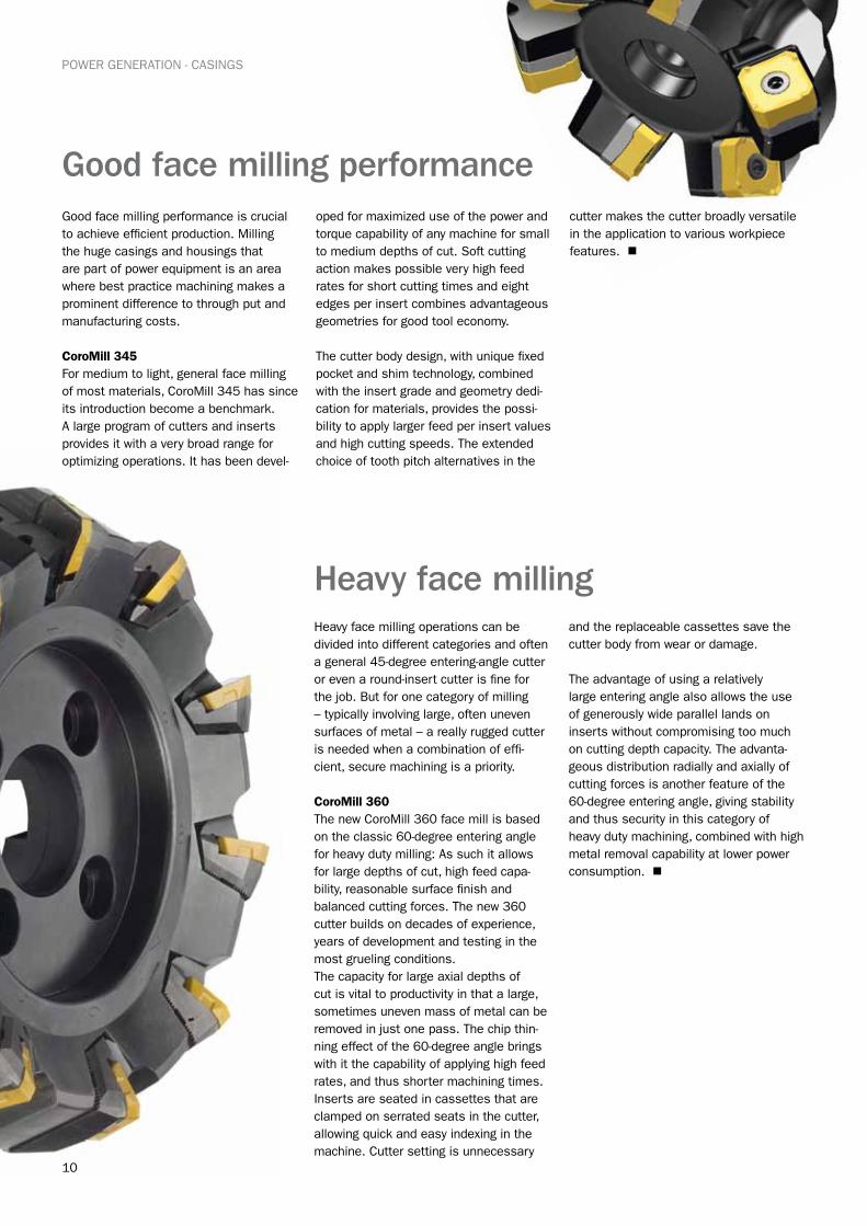
CoroMill 345For medium to light, general face milling of most materials, CoroMill 345 has since its introduction become a benchmark. A large program of cutters and inserts provides it with a very broad range for optimizing operations. It has been devel-
oped for maximized use of the power and torque capability of any machine for small to medium depths of cut. Soft cutting action makes possible very high feed rates for short cutting times and eight edges per insert combines advantageous geometries for good tool economy.
The cutter body design, with unique fixed pocket and shim technology, combined with the insert grade and geometry dedi-cation for materials, provides the possi-bility to apply larger feed per insert values and high cutting speeds. The extended choice of tooth pitch alternatives in the
cutter makes the cutter broadly versatile in the application to various workpiece features. n
Good face milling performance
Heavy face millingHeavy face milling operations can be divided into different categories and often a general 45-degree entering-angle cutter or even a round-insert cutter is fine for the job. But for one category of milling – typically involving large, often uneven surfaces of metal – a really rugged cutter is needed when a combination of effi-cient, secure machining is a priority.
CoroMill 360The new CoroMill 360 face mill is based on the classic 60-degree entering angle for heavy duty milling: As such it allows for large depths of cut, high feed capa-bility, reasonable surface finish and balanced cutting forces. The new 360 cutter builds on decades of experience, years of development and testing in the most grueling conditions.The capacity for large axial depths of cut is vital to productivity in that a large, sometimes uneven mass of metal can be removed in just one pass. The chip thin-ning effect of the 60-degree angle brings with it the capability of applying high feed rates, and thus shorter machining times. Inserts are seated in cassettes that are clamped on serrated seats in the cutter, allowing quick and easy indexing in the machine. Cutter setting is unnecessary
and the replaceable cassettes save the cutter body from wear or damage.
The advantage of using a relatively large entering angle also allows the use of generously wide parallel lands on inserts without compromising too much on cutting depth capacity. The advanta-geous distribution radially and axially of cutting forces is another feature of the 60-degree entering angle, giving stability and thus security in this category of heavy duty machining, combined with high metal removal capability at lower power consumption. n
11
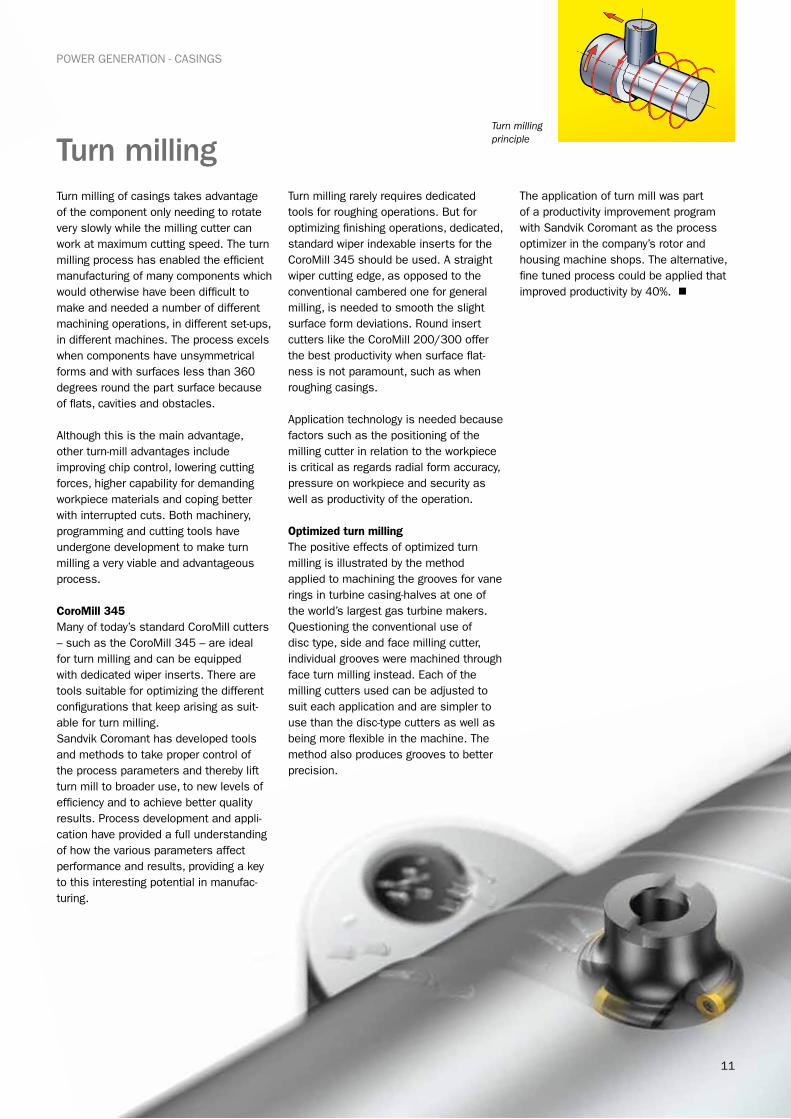
Turn milling Turn milling of casings takes advantage of the component only needing to rotate very slowly while the milling cutter can work at maximum cutting speed. The turn milling process has enabled the efficient manufacturing of many components which would otherwise have been difficult to make and needed a number of different machining operations, in different set-ups, in different machines. The process excels when components have unsymmetrical forms and with surfaces less than 360 degrees round the part surface because of flats, cavities and obstacles.
Although this is the main advantage, other turn-mill advantages include improving chip control, lowering cutting forces, higher capability for demanding workpiece materials and coping better with interrupted cuts. Both machinery, programming and cutting tools have undergone development to make turn milling a very viable and advantageous process.
CoroMill 345Many of today’s standard CoroMill cutters – such as the CoroMill 345 – are ideal for turn milling and can be equipped with dedicated wiper inserts. There are tools suitable for optimizing the different configurations that keep arising as suit-able for turn milling. Sandvik Coromant has developed tools and methods to take proper control of the process parameters and thereby lift turn mill to broader use, to new levels of efficiency and to achieve better quality results. Process development and appli-cation have provided a full understanding of how the various parameters affect performance and results, providing a key to this interesting potential in manufac-turing.
Turn milling rarely requires dedicated tools for roughing operations. But for optimizing finishing operations, dedicated, standard wiper indexable inserts for the CoroMill 345 should be used. A straight wiper cutting edge, as opposed to the conventional cambered one for general milling, is needed to smooth the slight surface form deviations. Round insert cutters like the CoroMill 200/300 offer the best productivity when surface flat-ness is not paramount, such as when roughing casings.
Application technology is needed because factors such as the positioning of the milling cutter in relation to the workpiece is critical as regards radial form accuracy, pressure on workpiece and security as well as productivity of the operation.
Optimized turn millingThe positive effects of optimized turn milling is illustrated by the method applied to machining the grooves for vane rings in turbine casing-halves at one of the world’s largest gas turbine makers. Questioning the conventional use of disc type, side and face milling cutter, individual grooves were machined through face turn milling instead. Each of the milling cutters used can be adjusted to suit each application and are simpler to use than the disc-type cutters as well as being more flexible in the machine. The method also produces grooves to better precision.
The application of turn mill was part of a productivity improvement program with Sandvik Coromant as the process optimizer in the company’s rotor and housing machine shops. The alternative, fine tuned process could be applied that improved productivity by 40%. n
POWER GENERATION - CASINGS
Turn milling principle
12
POWER GENERATION - CASINGS
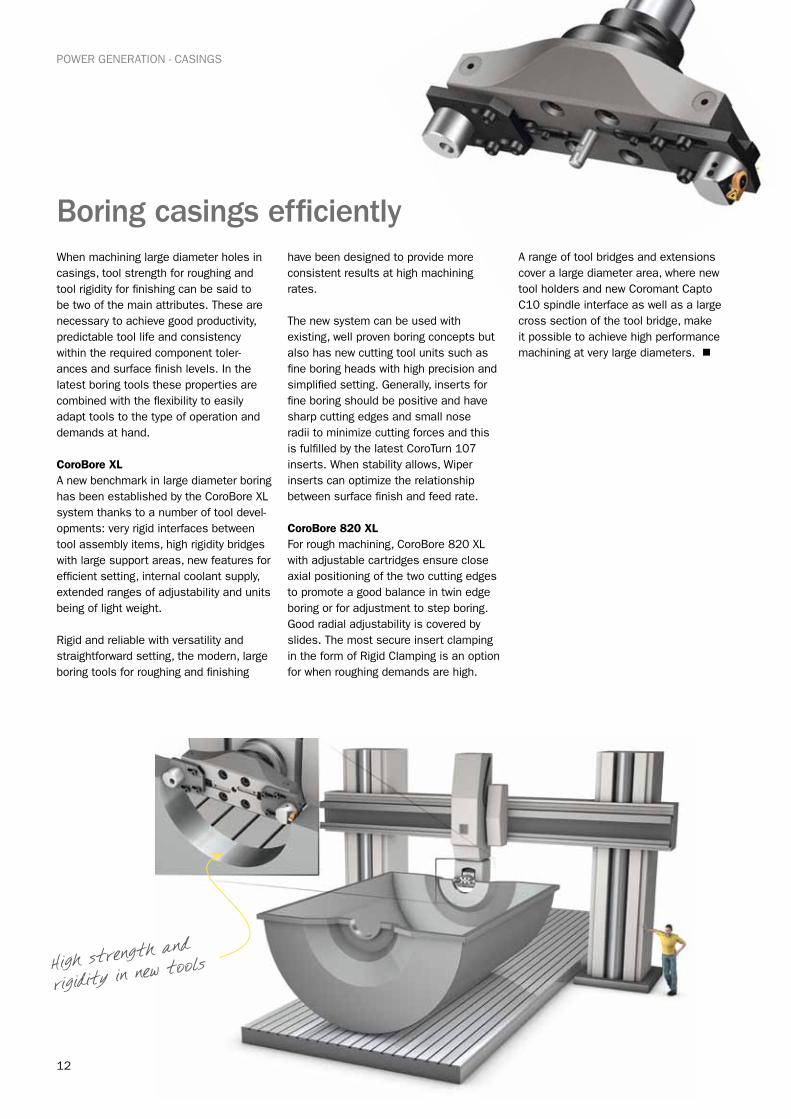
Boring casings efficientlyWhen machining large diameter holes in casings, tool strength for roughing and tool rigidity for finishing can be said to be two of the main attributes. These are necessary to achieve good productivity, predictable tool life and consistency within the required component toler-ances and surface finish levels. In the latest boring tools these properties are combined with the flexibility to easily adapt tools to the type of operation and demands at hand.
CoroBore XLA new benchmark in large diameter boring has been established by the CoroBore XL system thanks to a number of tool devel-opments: very rigid interfaces between tool assembly items, high rigidity bridges with large support areas, new features for efficient setting, internal coolant supply, extended ranges of adjustability and units being of light weight.
Rigid and reliable with versatility and straightforward setting, the modern, large boring tools for roughing and finishing
have been designed to provide more consistent results at high machining rates.
The new system can be used with existing, well proven boring concepts but also has new cutting tool units such as fine boring heads with high precision and simplified setting. Generally, inserts for fine boring should be positive and have sharp cutting edges and small nose radii to minimize cutting forces and this is fulfilled by the latest CoroTurn 107 inserts. When stability allows, Wiper inserts can optimize the relationship between surface finish and feed rate.
CoroBore 820 XLFor rough machining, CoroBore 820 XL with adjustable cartridges ensure close axial positioning of the two cutting edges to promote a good balance in twin edge boring or for adjustment to step boring. Good radial adjustability is covered by slides. The most secure insert clamping in the form of Rigid Clamping is an option for when roughing demands are high.
A range of tool bridges and extensions cover a large diameter area, where new tool holders and new Coromant Capto C10 spindle interface as well as a large cross section of the tool bridge, make it possible to achieve high performance machining at very large diameters. n
High strength and
rigidity in new tools
13
POWER GENERATION - SHAFTS
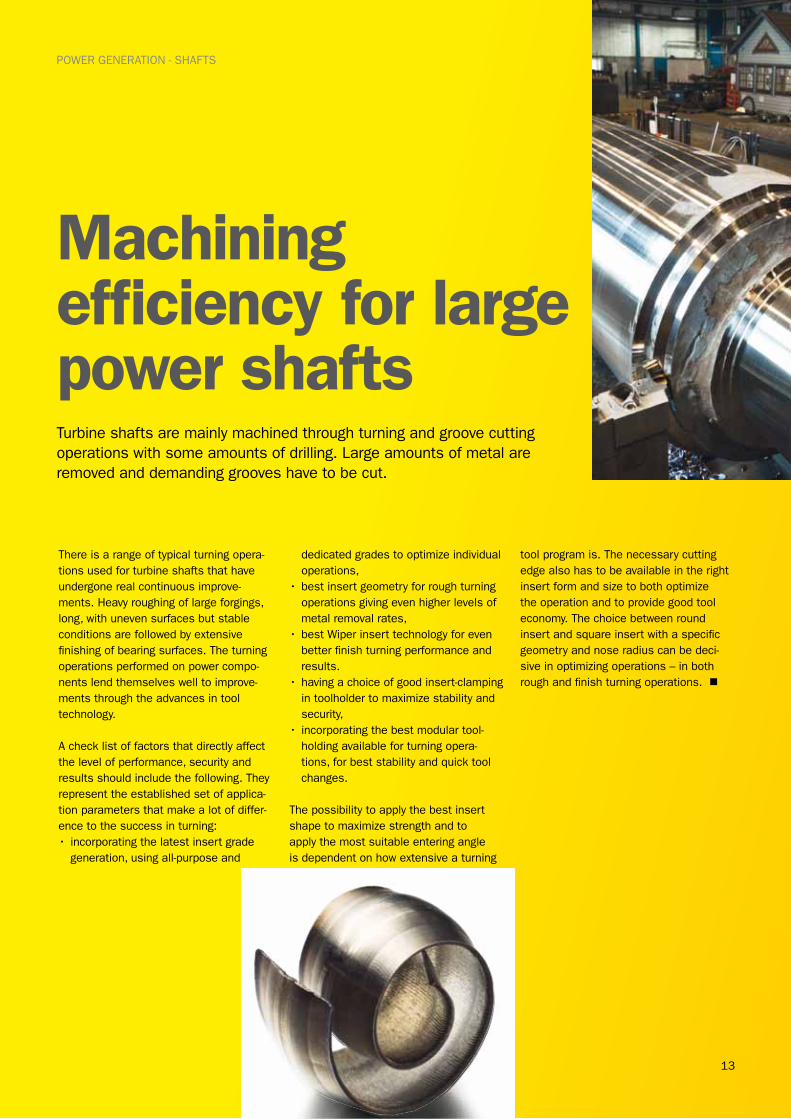
Machining efficiency for large power shafts Turbine shafts are mainly machined through turning and groove cutting operations with some amounts of drilling. Large amounts of metal are removed and demanding grooves have to be cut.
There is a range of typical turning opera-tions used for turbine shafts that have undergone real continuous improve-ments. Heavy roughing of large forgings, long, with uneven surfaces but stable conditions are followed by extensive finishing of bearing surfaces. The turning operations performed on power compo-nents lend themselves well to improve-ments through the advances in tool technology.
A check list of factors that directly affect the level of performance, security and results should include the following. They represent the established set of applica-tion parameters that make a lot of differ-ence to the success in turning:• incorporating the latest insert grade
generation, using all-purpose and
dedicated grades to optimize individual operations,
•best insert geometry for rough turning operations giving even higher levels of metal removal rates,
•best Wiper insert technology for even better finish turning performance and results.
•having a choice of good insert-clamping in toolholder to maximize stability and security,
• incorporating the best modular tool-holding available for turning opera-tions, for best stability and quick tool changes.
The possibility to apply the best insert shape to maximize strength and to apply the most suitable entering angle is dependent on how extensive a turning
tool program is. The necessary cutting edge also has to be available in the right insert form and size to both optimize the operation and to provide good tool economy. The choice between round insert and square insert with a specific geometry and nose radius can be deci-sive in optimizing operations – in both rough and finish turning operations. n
14
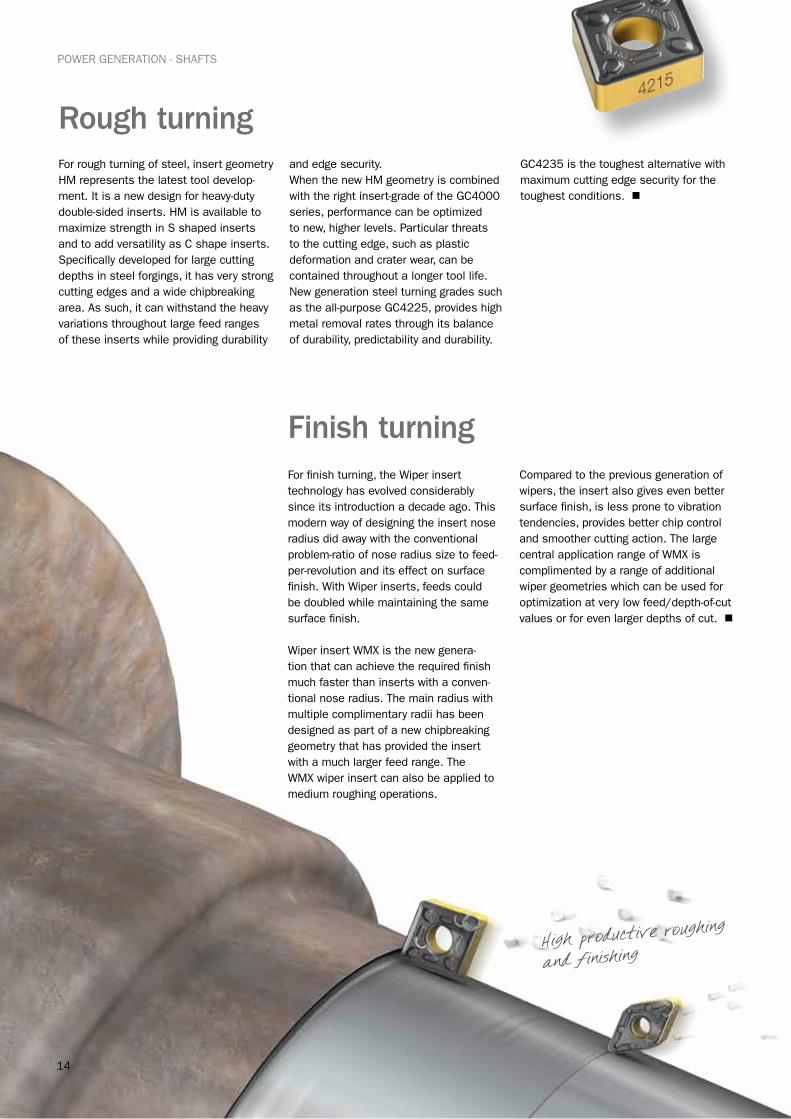
POWER GENERATION - SHAFTS
Rough turning For rough turning of steel, insert geometry HM represents the latest tool develop-ment. It is a new design for heavy-duty double-sided inserts. HM is available to maximize strength in S shaped inserts and to add versatility as C shape inserts. Specifically developed for large cutting depths in steel forgings, it has very strong cutting edges and a wide chipbreaking area. As such, it can withstand the heavy variations throughout large feed ranges of these inserts while providing durability
and edge security. When the new HM geometry is combined with the right insert-grade of the GC4000 series, performance can be optimized to new, higher levels. Particular threats to the cutting edge, such as plastic deformation and crater wear, can be contained throughout a longer tool life. New generation steel turning grades such as the all-purpose GC4225, provides high metal removal rates through its balance of durability, predictability and durability.
GC4235 is the toughest alternative with maximum cutting edge security for the toughest conditions. n
Finish turningFor finish turning, the Wiper insert technology has evolved considerably since its introduction a decade ago. This modern way of designing the insert nose radius did away with the conventional problem-ratio of nose radius size to feed-per-revolution and its effect on surface finish. With Wiper inserts, feeds could be doubled while maintaining the same surface finish.
Wiper insert WMX is the new genera-tion that can achieve the required finish much faster than inserts with a conven-tional nose radius. The main radius with multiple complimentary radii has been designed as part of a new chipbreaking geometry that has provided the insert with a much larger feed range. The WMX wiper insert can also be applied to medium roughing operations.
Compared to the previous generation of wipers, the insert also gives even better surface finish, is less prone to vibration tendencies, provides better chip control and smoother cutting action. The large central application range of WMX is complimented by a range of additional wiper geometries which can be used for optimization at very low feed/depth-of-cut values or for even larger depths of cut. n
High productive roughing
and finishing
15
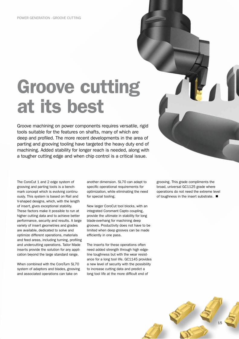
POWER GENERATION - GROOVE CUTTING
Groove cutting at its best Groove machining on power components requires versatile, rigid tools suitable for the features on shafts, many of which are deep and profiled. The more recent developments in the area of parting and grooving tooling have targeted the heavy duty end of machining. Added stability for longer reach is needed, along with a tougher cutting edge and when chip control is a critical issue.
The CoroCut 1 and 2 edge system of grooving and parting tools is a bench-mark concept which is evolving continu-ously. This system is based on Rail and V-shaped designs, which, with the length of insert, gives exceptional stability. These factors make it possible to run at higher cutting data and to achieve better performance, security and results. A large variety of insert geometries and grades are available, dedicated to solve and optimize different operations, materials and feed areas, including turning, profiling and undercutting operations. Tailor Made inserts provide the solution for any appli-cation beyond the large standard range.
When combined with the CoroTurn SL70 system of adaptors and blades, grooving and associated operations can take on
another dimension. SL70 can adapt to specific operational requirements for optimization, while eliminating the need for special tooling.
New larger CoroCut tool blocks, with an integrated Coromant Capto coupling, provide the ultimate in stability for long blade-overhang for machining deep grooves. Productivity does not have to be limited when deep grooves can be made efficiently in one pass.
The inserts for these operations often need added strength through high edge-line toughness but with the wear resist-ance for a long tool life. GC1145 provides a new level of security with the possibility to increase cutting data and predict a long tool life at the more difficult end of
grooving. This grade compliments the broad, universal GC1125 grade where operations do not need the extreme level of toughness in the insert substrate. n
16
POWER GENERATION - GROOVE CUTTING
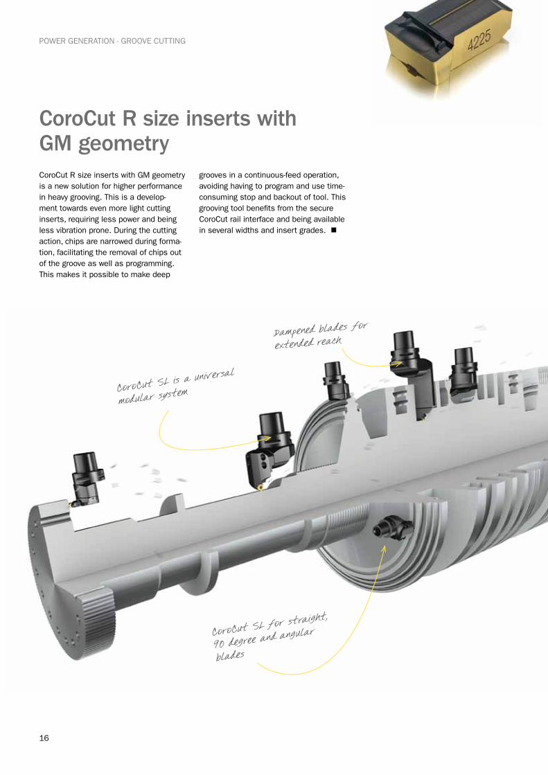
CoroCut R size inserts with GM geometryCoroCut R size inserts with GM geometry is a new solution for higher performance in heavy grooving. This is a develop-ment towards even more light cutting inserts, requiring less power and being less vibration prone. During the cutting action, chips are narrowed during forma-tion, facilitating the removal of chips out of the groove as well as programming. This makes it possible to make deep
grooves in a continuous-feed operation, avoiding having to program and use time-consuming stop and backout of tool. This grooving tool benefits from the secure CoroCut rail interface and being available in several widths and insert grades. n
CoroCut SL is a universa
l
modular system
Dampened blades for
extended reach
CoroCut SL for straight
,
90 degree and angular
blades
17
POWER GENERATION - DISCS, RINGS AND DIAPHRAGMS
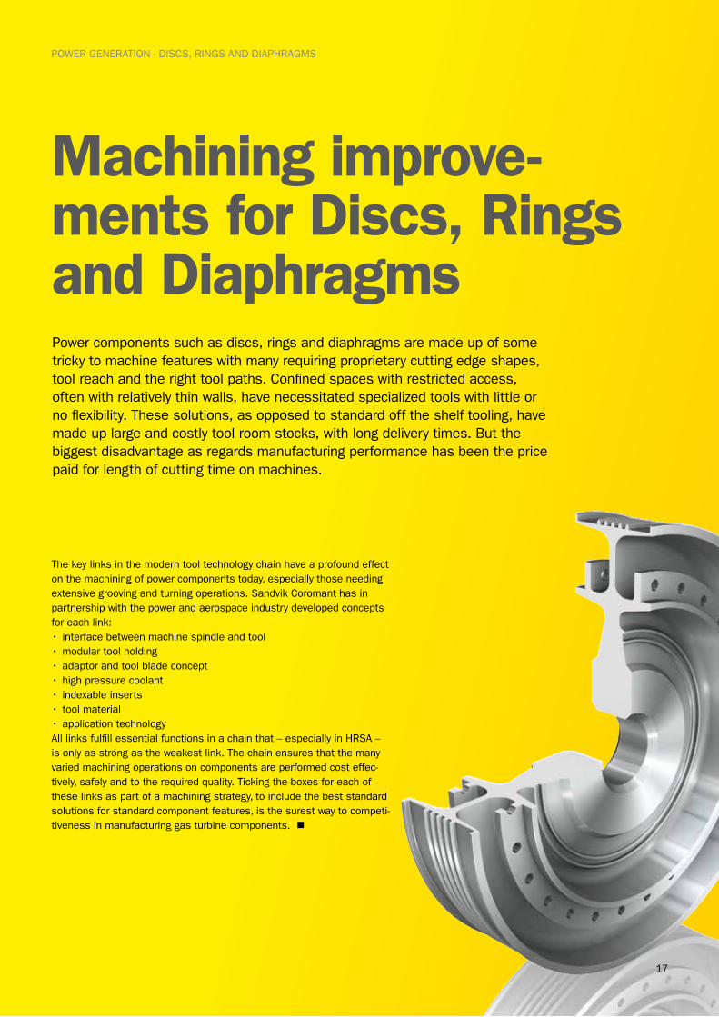
Machining improve-ments for Discs, Rings and DiaphragmsPower components such as discs, rings and diaphragms are made up of some tricky to machine features with many requiring proprietary cutting edge shapes, tool reach and the right tool paths. Confined spaces with restricted access, often with relatively thin walls, have necessitated specialized tools with little or no flexibility. These solutions, as opposed to standard off the shelf tooling, have made up large and costly tool room stocks, with long delivery times. But the biggest disadvantage as regards manufacturing performance has been the price paid for length of cutting time on machines.
The key links in the modern tool technology chain have a profound effect on the machining of power components today, especially those needing extensive grooving and turning operations. Sandvik Coromant has in partnership with the power and aerospace industry developed concepts for each link: • interface between machine spindle and tool•modular tool holding•adaptor and tool blade concept•high pressure coolant• indexable inserts• tool material•application technologyAll links fulfill essential functions in a chain that – especially in HRSA – is only as strong as the weakest link. The chain ensures that the many varied machining operations on components are performed cost effec-tively, safely and to the required quality. Ticking the boxes for each of these links as part of a machining strategy, to include the best standard solutions for standard component features, is the surest way to competi-tiveness in manufacturing gas turbine components. n
18
POWER GENERATION - DISCS, RINGS AND DIAPHRAGMS
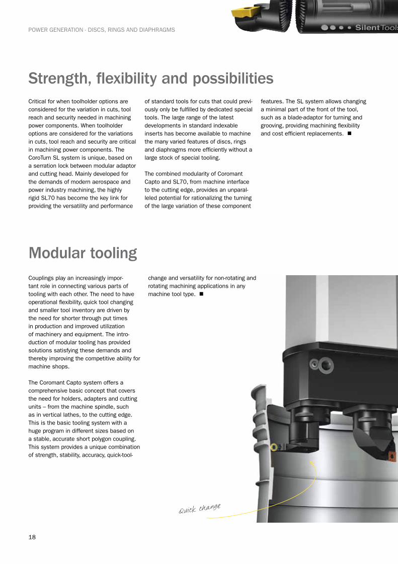
Modular toolingCouplings play an increasingly impor-tant role in connecting various parts of tooling with each other. The need to have operational flexibility, quick tool changing and smaller tool inventory are driven by the need for shorter through put times in production and improved utilization of machinery and equipment. The intro-duction of modular tooling has provided solutions satisfying these demands and thereby improving the competitive ability for machine shops.
The Coromant Capto system offers a comprehensive basic concept that covers the need for holders, adapters and cutting units – from the machine spindle, such as in vertical lathes, to the cutting edge. This is the basic tooling system with a huge program in different sizes based on a stable, accurate short polygon coupling. This system provides a unique combination of strength, stability, accuracy, quick-tool-
change and versatility for non-rotating and rotating machining applications in any machine tool type. n
Strength, flexibility and possibilitiesCritical for when toolholder options are considered for the variation in cuts, tool reach and security needed in machining power components. When toolholder options are considered for the variations in cuts, tool reach and security are critical in machining power components. The CoroTurn SL system is unique, based on a serration lock between modular adaptor and cutting head. Mainly developed for the demands of modern aerospace and power industry machining, the highly rigid SL70 has become the key link for providing the versatility and performance
of standard tools for cuts that could previ-ously only be fulfilled by dedicated special tools. The large range of the latest developments in standard indexable inserts has become available to machine the many varied features of discs, rings and diaphragms more efficiently without a large stock of special tooling.
The combined modularity of Coromant Capto and SL70, from machine interface to the cutting edge, provides an unparal-leled potential for rationalizing the turning of the large variation of these component
features. The SL system allows changing a minimal part of the front of the tool, such as a blade-adaptor for turning and grooving, providing machining flexibility and cost efficient replacements. n
Quick change
19
POWER GENERATION - DISCS, RINGS AND DIAPHRAGMS
Any tool is only as good as the cutting edgeIndexable inserts having round cutting edges are the most suitable for the type of operations involved for the groove and profiling features. Tool material development has moved performance considerably forward for HRSA and titanium machining with new insert grade and geometries. Rapid notch wear is a common destructive factor in these component materials and is at its worst when using a tool having a cutting edge at a 90 degree entering angle. A round insert cutting edge gives a variable angle from zero to a maximum of forty five degrees (if the depth of cut is smaller than 15% of the insert diameter), and this lends itself very well to the various pocketing operations and for minimizing pressure on thin walls.
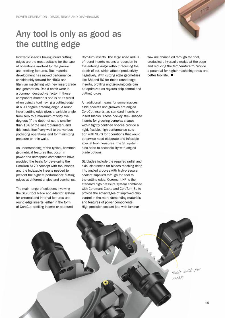
An understanding of the typical, common geometrical features that occur in power and aerospace components have provided the basis for developing the CoroTurn SL70 concept with tool blades and the indexable inserts needed to present the highest performance cutting edges at different angles and overhangs.
The main range of solutions involving the SL70 tool blade and adaptor system for external and internal features use round edge inserts, either in the form of CoroCut profiling inserts or as round
CoroTurn inserts. The large nose radius of round inserts means a reduction in the entering angle without reducing the depth of cut, which affects productivity negatively. With cutting edge geometries like SM and RO for these round edge inserts, profiling and grooving cuts can be optimized as regards chip control and cutting forces.
An additional means for some inacces-sible pockets and grooves are angled CoroCut inserts, as standard inserts or insert blanks. These hockey stick shaped inserts for grooving complex shapes within tightly confined spaces provide a rigid, flexible, high performance solu-tion with SL70 for operations that would otherwise need elaborate and inflexible special tool measures. The SL system also adds to accessibility with angled blade options.
SL blades include the required radial and axial clearances for blades reaching deep into angled grooves with high-pressure coolant supplied through the tool to the cutting edge. Coromant HP is the standard high pressure system combined with Coromant Capto and CoroTurn SL to provide the advantages of improved chip control in the more demanding materials and features of power components. High precision coolant jets with laminar
flow are channeled through the tool, producing a hydraulic wedge at the edge and reducing the temperature to provide a potential for higher machining rates and better tool life. n
Tools built for
access
20
Cutting edge optimizersPower component machining in demanding HRSA materials can in some cases be optimized by using the right, modern ceramic indexable insert. These have a higher resistance to notch wear, allowing for higher depths of cut. Also longer lengths of cut can be taken and profiling of pockets can be performed efficiently using more sophisticated tool paths, thereby utilizing the wear resist-ance of the insert more fully. Ceramic grades CC6060 and CC6065 complement each other, with CC6060 having very high notch wear resistance for turning pre-machined components and ideal for roll-in and -out methods in
corners and grooves. CC6065 can take on forgings and copes better with plunging directly into grooves and corners. n
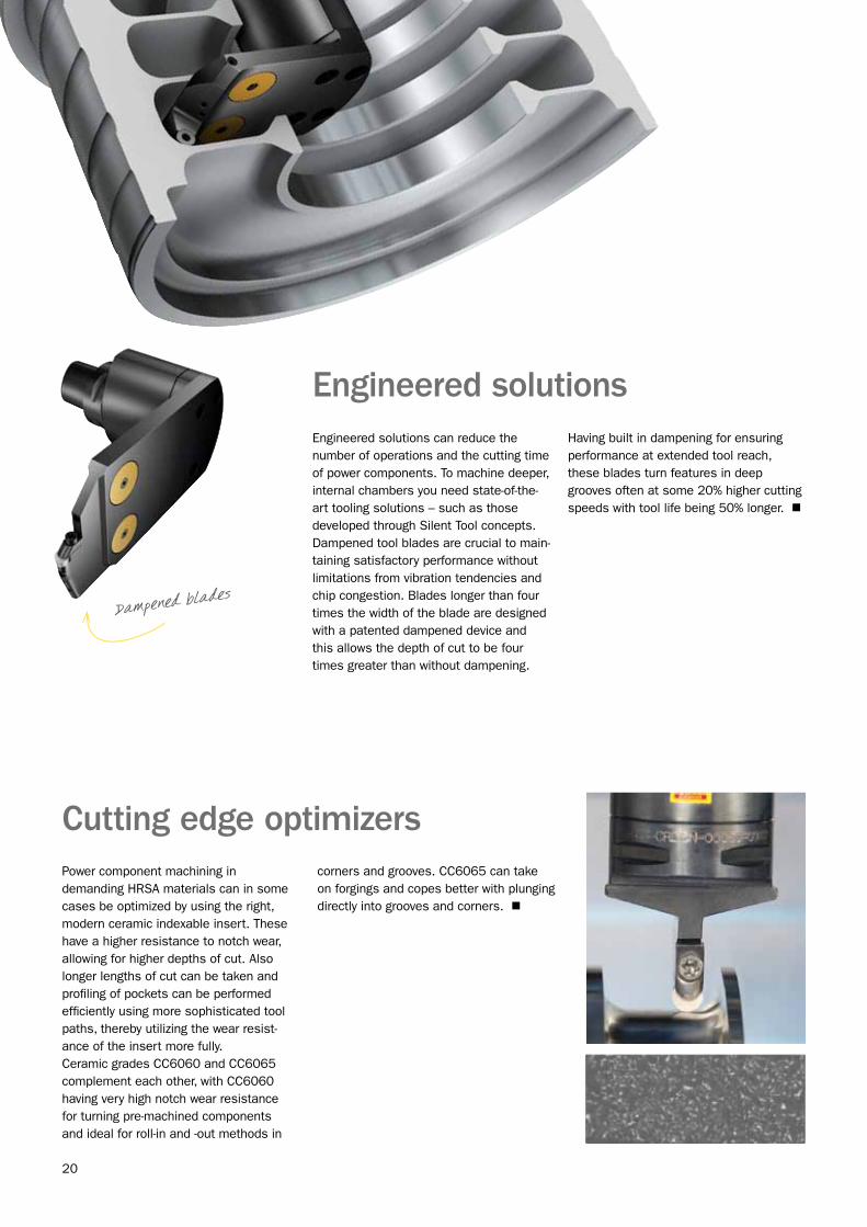
Engineered solutionsEngineered solutions can reduce the number of operations and the cutting time of power components. To machine deeper, internal chambers you need state-of-the-art tooling solutions – such as those developed through Silent Tool concepts. Dampened tool blades are crucial to main-taining satisfactory performance without limitations from vibration tendencies and chip congestion. Blades longer than four times the width of the blade are designed with a patented dampened device and this allows the depth of cut to be four times greater than without dampening.
Having built in dampening for ensuring performance at extended tool reach, these blades turn features in deep grooves often at some 20% higher cutting speeds with tool life being 50% longer. n
Dampened blades
21
POWER GENERATION - DISCS, RINGS AND DIAPHRAGMS
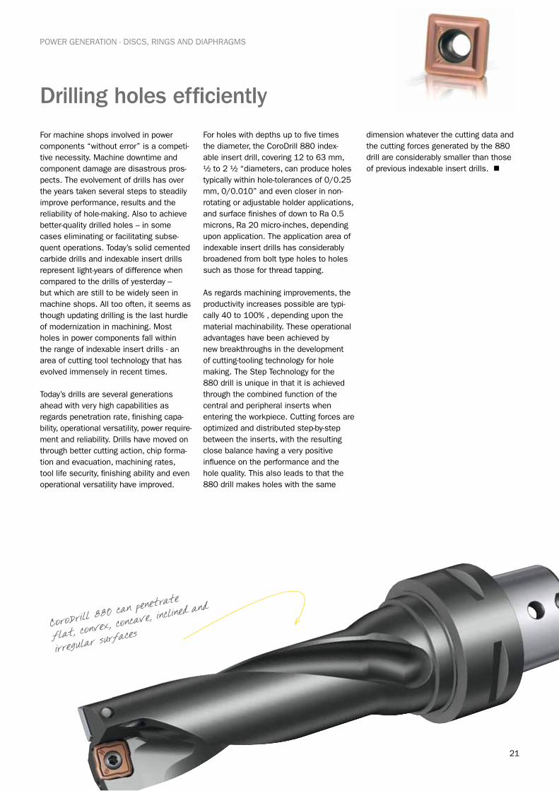
Drilling holes efficiently
For machine shops involved in power components “without error” is a competi-tive necessity. Machine downtime and component damage are disastrous pros-pects. The evolvement of drills has over the years taken several steps to steadily improve performance, results and the reliability of hole-making. Also to achieve better-quality drilled holes – in some cases eliminating or facilitating subse-quent operations. Today’s solid cemented carbide drills and indexable insert drills represent light-years of difference when compared to the drills of yesterday – but which are still to be widely seen in machine shops. All too often, it seems as though updating drilling is the last hurdle of modernization in machining. Most holes in power components fall within the range of indexable insert drills - an area of cutting tool technology that has evolved immensely in recent times. Today’s drills are several generations ahead with very high capabilities as regards penetration rate, finishing capa-bility, operational versatility, power require-ment and reliability. Drills have moved on through better cutting action, chip forma-tion and evacuation, machining rates, tool life security, finishing ability and even operational versatility have improved.
For holes with depths up to five times the diameter, the CoroDrill 880 index-able insert drill, covering 12 to 63 mm, ½ to 2 ½ “diameters, can produce holes typically within hole-tolerances of 0/0.25 mm, 0/0.010” and even closer in non-rotating or adjustable holder applications, and surface finishes of down to Ra 0.5 microns, Ra 20 micro-inches, depending upon application. The application area of indexable insert drills has considerably broadened from bolt type holes to holes such as those for thread tapping.
As regards machining improvements, the productivity increases possible are typi-cally 40 to 100% , depending upon the material machinability. These operational advantages have been achieved by new breakthroughs in the development of cutting-tooling technology for hole making. The Step Technology for the 880 drill is unique in that it is achieved through the combined function of the central and peripheral inserts when entering the workpiece. Cutting forces are optimized and distributed step-by-step between the inserts, with the resulting close balance having a very positive influence on the performance and the hole quality. This also leads to that the 880 drill makes holes with the same
dimension whatever the cutting data and the cutting forces generated by the 880 drill are considerably smaller than those of previous indexable insert drills. n
CoroDrill 880 can
penetrate
flat, convex, conc
ave, inclined and
irregular surfaces

22
POWER GENERATION - METHOD APPLICATION
Method application makes the differenceCutting tools evolve continuously providing improvements in manufacturing, Sandvik Coromant sees tool development as going hand in hand with machining methods development for users to achieve the very best from their tools and production facili-ties. This is part of the Your Success in Focus approach. To apply basic good prac-tice of machining is important to arrive at good machining solutions – but new tool concepts in modern machines also open the door to new optimization possibilities.
External circular milling
Circular ramping helical interpolation
Linear ramping, 2 axes
Closed pocket milling, 4 to 5 axes
Internal circular ramping
23
POWER GENERATION - METHOD APPLICATION
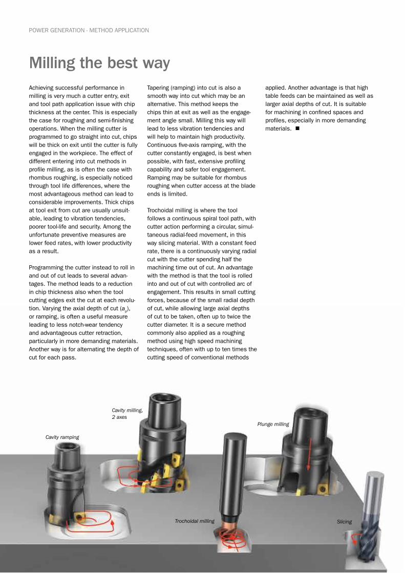
Milling the best wayAchieving successful performance in milling is very much a cutter entry, exit and tool path application issue with chip thickness at the center. This is especially the case for roughing and semi-finishing operations. When the milling cutter is programmed to go straight into cut, chips will be thick on exit until the cutter is fully engaged in the workpiece. The effect of different entering into cut methods in profile milling, as is often the case with rhombus roughing, is especially noticed through tool life differences, where the most advantageous method can lead to considerable improvements. Thick chips at tool exit from cut are usually unsuit-able, leading to vibration tendencies, poorer tool-life and security. Among the unfortunate preventive measures are lower feed rates, with lower productivity as a result.
Programming the cutter instead to roll in and out of cut leads to several advan-tages. The method leads to a reduction in chip thickness also when the tool cutting edges exit the cut at each revolu-tion. Varying the axial depth of cut (a
p), or ramping, is often a useful measure leading to less notch-wear tendency and advantageous cutter retraction, particularly in more demanding materials. Another way is for alternating the depth of cut for each pass.
Tapering (ramping) into cut is also a smooth way into cut which may be an alternative. This method keeps the chips thin at exit as well as the engage-ment angle small. Milling this way will lead to less vibration tendencies and will help to maintain high productivity. Continuous five-axis ramping, with the cutter constantly engaged, is best when possible, with fast, extensive profiling capability and safer tool engagement. Ramping may be suitable for rhombus roughing when cutter access at the blade ends is limited.
Trochoidal milling is where the tool follows a continuous spiral tool path, with cutter action performing a circular, simul-taneous radial-feed movement, in this way slicing material. With a constant feed rate, there is a continuously varying radial cut with the cutter spending half the machining time out of cut. An advantage with the method is that the tool is rolled into and out of cut with controlled arc of engagement. This results in small cutting forces, because of the small radial depth of cut, while allowing large axial depths of cut to be taken, often up to twice the cutter diameter. It is a secure method commonly also applied as a roughing method using high speed machining techniques, often with up to ten times the cutting speed of conventional methods
applied. Another advantage is that high table feeds can be maintained as well as larger axial depths of cut. It is suitable for machining in confined spaces and profiles, especially in more demanding materials. n
Cavity ramping
Cavity milling, 2 axes
Plunge milling
Trochoidal milling Slicing

24
lm
Dm1
fn
SCL
POWER GENERATION - METHOD APPLICATION
Turning demanding materialsMachining demanding materials such as heat resistant super alloys and some stainless steels today demand an up to date machining strategy. The combina-tion of different material properties sets machinability levels and the importance for the right approach to achieve high productivity: plan the machining strategy, use the right insert approach, select the best insert/tool characteristics, program the best tool paths and cutting data, use spiral cutting length calculation and apply coolant correctly .
A major factor that affects the cutting action in the demanding alloys used for turning power components is the approach of the cutting edge. The choice of entering angle has direct conse-quences for the productivity and process reliability. It affects the chip thickness, the feed rate, cutting forces as well as the type of cuts that can be taken with the tool. The entering angle will influence the insert shape and the nose radius and how well the insert grade can be utilized. The most suitable for super-alloy turning is when the angle is equal to or less than 45 degrees and the worst condition is when the entering angle is 90 degrees or when the depth of cut is larger than the nose radius of the insert. A small entering angle means a thin chip and higher feeds. This has led to the frequent use of round insert shape for this area.
It provides strength to allow a sharper, more positive cutting edge and gener-ates a chip thickness that varies along a long cutting edge, thus allowing high feed rates. The large insert radius does not restrict the feed rate because of surface finish. The round insert also gives the programming flexibility to perform profiling and pocketing operations required by many component shapes.
A square insert is often the most suitable for some rough machining operations, with its capacity for heavy cuts in various directions with a 45 degree entering angle. The C shape insert has built in flexibility as regards tool paths and when extended to be an Xcel type insert, provides even more tool accessibility into corners, shoulders and recesses as well as high performance. This insert also reduces radial cutting forces, gives a constant chip thickness and reduces notch wear. The result is higher produc-tivity, longer tool life and better security.
Tool life prediction is important. Because inserts have a relatively shorter tool life when turning demanding alloys, one insert can in some cases only machine a limited number of passes before needing to be indexed. The spiral cutting length calculation is an ideal method with which to predict the tool life of an insert edge. This, to avoid unwanted insert changes in
the middle of cuts, especially in finishing. A range of cutting speeds allow for different lengths of cut. The length value and each spiral length graph is only appli-cable for that particular insert, geometry, grade, depth of cut and material and a formula calculates specific values. n
Each spiral cutting length graph is unique for an application and is invaluable for predicting tool life, especially when turning demanding materials.
CoroCut grooving tools have a unique
rail system for maximum stability
n
m
fl
diaSCL ××= π
25
POWER GENERATION - METHOD APPLICATION
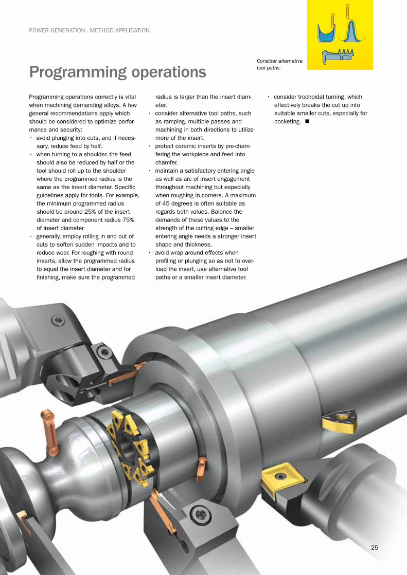
Programming operationsProgramming operations correctly is vital when machining demanding alloys. A few general recommendations apply which should be considered to optimize perfor-mance and security:• avoid plunging into cuts, and if neces-
sary, reduce feed by half.• when turning to a shoulder, the feed
should also be reduced by half or the tool should roll up to the shoulder where the programmed radius is the same as the insert diameter. Specific guidelines apply for tools. For example, the minimum programmed radius should be around 25% of the insert diameter and component radius 75% of insert diameter.
• generally, employ rolling in and out of cuts to soften sudden impacts and to reduce wear. For roughing with round inserts, allow the programmed radius to equal the insert diameter and for finishing, make sure the programmed
radius is larger than the insert diam-eter.
• consider alternative tool paths, such as ramping, multiple passes and machining in both directions to utilize more of the insert.
• protect ceramic inserts by pre-cham-fering the workpiece and feed into chamfer.
• maintain a satisfactory entering angle as well as arc of insert engagement throughout machining but especially when roughing in corners. A maximum of 45 degrees is often suitable as regards both values. Balance the demands of these values to the strength of the cutting edge – smaller entering angle needs a stronger insert shape and thickness.
• avoid wrap around effects when profiling or plunging so as not to over-load the insert, use alternative tool paths or a smaller insert diameter.
• consider trochoidal turning, which effectively breaks the cut up into suitable smaller cuts, especially for pocketing. n
Consider alternative tool paths.
26
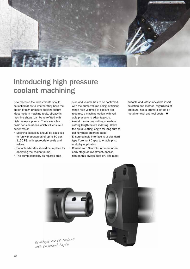
Introducing high pressure coolant machiningNew machine tool investments should be looked at as to whether they have the option of high pressure coolant supply. Most modern machine tools, already in machine shops, can be retrofitted with high pressure pumps. There are a few basic considerations which will ensure a better result:•Machine capability should be specified
to run with pressures of up to 80 bar, 1150 PSI with appropriate seals and valves.
•Suitable M-codes should be in place for operating the coolant pump.
•The pump capability as regards pres-
sure and volume has to be confirmed, with the pump volume being sufficient. When high volumes of coolant are required, a machine option with vari-able pressure is advantageous.
•Aim at maximizing cutting speeds or cutting length before indexing. Utilize the spiral cutting length for long cuts to define where program stops.
•Ensure spindle interface is of standard type Coromant Capto to enable plug and play application.
•Consult with Sandvik Coromant at an early stage of investment/applica-tion as this always pays off. The most
suitable and latest indexable insert selection and method, regardless of pressure, has a dramatic effect on metal removal and tool costs. n
Strategic use of coolant
with Coromant Capto
27
Basic application principles to achieve advanced millingChip thickness is an important factor in applying milling tools, with maximum chip thickness being the primary parameter. It is the most important consideration for establishing the best feed per tooth for optimum performance. There are three main phases of chip formation to consider for applying the milling cutter to achieve good cutting action. As it is basically an intermittent and cyclical processes, a chip is generated to a certain length but to varying thickness. These are determined by the position of the tool, relationship between cutter diameter and the extent of the tool engagement. The main phases of chip formation during the cut are: entrance into cut, arc of engagement and exit from cut.
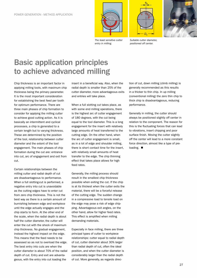
Certain relationships between the milling cutter and radial depth of cut are disadvantageous to performance. When a full slotting-cut is performed, a negative entry into cut is unavoidable as the cutting edges have to enter cut from zero chip thickness. This is not the best way as there is a certain amount of burnishing between edge and workpiece until the edge actually engages and the chip starts to form. At the other end of the scale, when the radial depth is about half the cutter diameter, the cutter will enter the cut with the shock of maximum chip thickness. No gradual engagement, instead the highest impact on the edge. This means that the feed needs to be assessed so as not to overload the edge. The best entry into cuts are when the cutter diameter is about 70% of the radial depth of cut. Entry and exit are advanta-geous, with the entry into cut loading the
insert in a beneficial way. Also, when the radial depth is smaller than 25% of the cutter diameter, more advantageous exits and entries will take place.
When a full slotting cut takes place, as with some end milling operations, there is the highest arc of cutter engagement of 180 degrees, with the cut being equal to the tool diameter. This is a long engagement for the insert with relatively large amounts of heat transferred to the cutting edge. On the other hand, when the arc of cutter engagement is small, as in a lot of edge and shoulder milling, there is short contact time for the insert, with relatively small amounts of heat transfer to the edge. The chip thinning effect that takes place allows for high feed rates.
Generally, the milling process should result in the smallest chip thickness possible when exiting the cut. If the chip is at its thickest when the cutter exits the material, there will be a forceful release of the cutting edge. The sudden change in a compressive load to tensile load on the edge may pose a risk of edge chip-ping. Advantageous exit angles, on the other hand, allow for higher feed rates. This effect is amplified when milling demanding materials.
Especially in face milling, there are three principal types of cutter to workpiece relationships: cutter equal to radial depth of cut, cutter diameter about 30% larger than radial depth of cut, often the ideal position, and when the cutter diameter is considerably larger than the radial depth of cut. More generally, as regards direc-
tion of cut, down milling (climb milling) is generally recommended as this results in a thicker to thin chip. In up milling (conventional milling) the zero thin chip to thick chip is disadvantageous, reducing performance.
Generally in milling, the cutter should always be positioned slightly off center in relation to the component. The reason for this is the fluctuating forces that can lead to vibrations, insert chipping and poor surface finish. Moving the cutter slightly off the center will lead to a more constant force direction, almost like a type of pre-loading. n
POWER GENERATION - METHOD APPLICATION
The least sensitive cutter entry in milling.
Suitable cutter diameter, positioned off center.
For more information, call 1-800-SANDVIK (1-800-726-3845).Or visit our website at www.sandvik.coromant.com/us
E-mail: [email protected]
C-2940:139 US/01 © AB Sandvik Coromant 2012.02