Embed Size (px)
Citation preview
Vishay Electronic GmbH
Hofmark-Aich-Str.36
D-84030 Landshut
Telefon +49 871 86-0
www.vishay.com
Document number: 13157 - Rev. 02
__________________________________________________________________________________________
QUALITY MANAGEMENT
Certified by VDE according to
DIN EN ISO 9001
Reg. No. 2556/QM/03.94
Power Factor Correction Controller
ESTAmat PFC-N
Operating Instruction MV1181
___________________________________________________________________________
ESTAmat PFC-N D.No.13157 - Rev. 02
Operating Instruction MV1181 Page 2 of 36
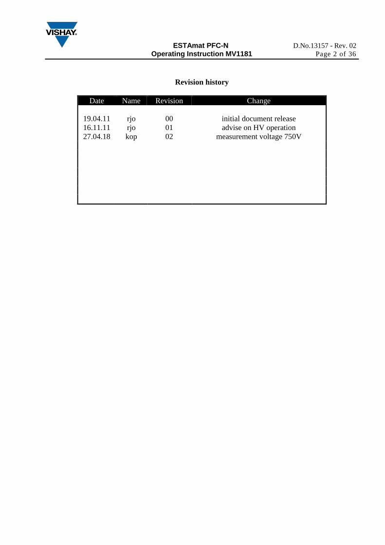
Revision history
Date Name Revision Change
19.04.11
16.11.11
rjo
rjo
00
01
initial document release
advise on HV operation
27.04.18 kop 02 measurement voltage 750V
ESTAmat PFC-N D.No.13157 - Rev. 02
Operating Instruction MV1181 Page 3 of 36
1 INSTALLATION AND CONNECTION .......................................................................... 4
1.1 Wiring diagram .......................................................................................................... 4
1.2 Connection data .......................................................................................................... 6
2 COMMISSIONING ........................................................................................................... 7
2.1 ESTAMAT PFC-N is parameterized: ........................................................................ 7
2.2 ESTAMAT PFC-N is not parameterized: .................................................................. 7
3 DISPLAY ........................................................................................................................... 8
4 MENU ESTAMAT PFC-N ................................................................................................ 9
4.1 Measurement menu .................................................................................................... 9
4.2 Info (Step database) .................................................................................................. 10
4.3 Manual (step switching manual) .............................................................................. 11
4.4 Setup (Quick start menu) .......................................................................................... 12
5 EXPERT MENU ESTAMAT PFC-N .............................................................................. 13
5.1 100 Quick start menu ................................................................................................... 13
5.2 200 Measurement settings ........................................................................................ 15
5.3 300 Setup Control System ........................................................................................ 17
5.4 400 Setup Step Database .......................................................................................... 21
5.5 500 Setup Alarm ....................................................................................................... 23
5.6 600 Resetmenu ......................................................................................................... 25
6 TECHNIAL DATA .......................................................................................................... 26
7 TROUBLESHOOTING ................................................................................................... 27
8 APPLICATIONS ............................................................................................................. 29
8.1 Fan Control ............................................................................................................... 29
8.2 Switching on target Pf 2 via digital input ................................................................. 30
8.3 Problems with the Step recognition. ........................................................................ 31
8.4 Transformer compensation ....................................................................................... 32
8.5 Reset defective steps respectively add aditional steps ............................................. 33
9 CUSTOMER SETTINGS ................................................................................................ 34
10 INDEX ......................................................................................................................... 35
11 APPENDIX .................................................................................................................. 36
11.1 Settings phase angle ................................................................................................. 36
11.2 Connections for mixed measurement ....................................................................... 36
ESTAmat PFC-N D.No.13157 - Rev. 02
Operating Instruction MV1181 Page 4 of 36
INSTALLATION AND CONNECTION
Only qualified staff is allowed to perform the installation. Also there have to be
kept all valid rules from government! Before connecting the device check that all
lines are without voltage and shorten current transformer.
1) Compare auxiliary-, measurement-, control voltage, frequency and the current path of the device
(see type label) with the data of the electricity network.
2) Assemble the relay in the switch panel with the 2 mounting clips. If the device is not fitting in
the cut out the small plastic bars on the side of the case can be removed with a knife.
3) Connect protective ground to the terminal link of the case.
4) Connect in accordance to the wiring diagram. Pay special attention to the cross section size of
the CT connections! A combined power supply and measurement ensures a safe shutdown of
capacitors at low voltage.
5) Remove short circuit links of the current transformer
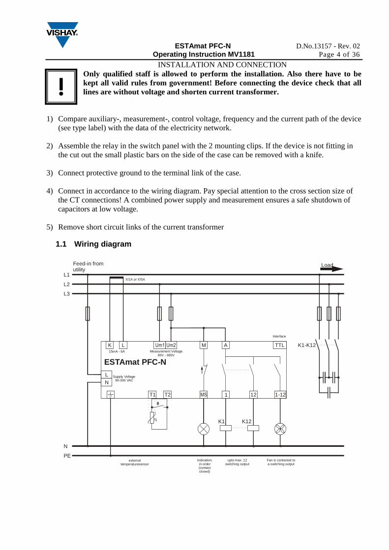
1.1 Wiring diagram
Load
T
K L Um1 Um2 AM
MS 1 12 1-12T1 T2
externaltemperaturesensor
upto max. 12switching output
Fan is contacted toa switching output
Indication:in order(contact closed)
K1 K12
K1-K12
L1
L2
L3
N
PE
ESTAmat PFC-N
TTL
Interface
X/1A or X/5A
15mA - 6A Measurement Voltage90V - 690V
Feed-in from utility
L
N
Supply Voltage90-300 VAC
!
ESTAmat PFC-N D.No.13157 - Rev. 02
Operating Instruction MV1181 Page 5 of 36
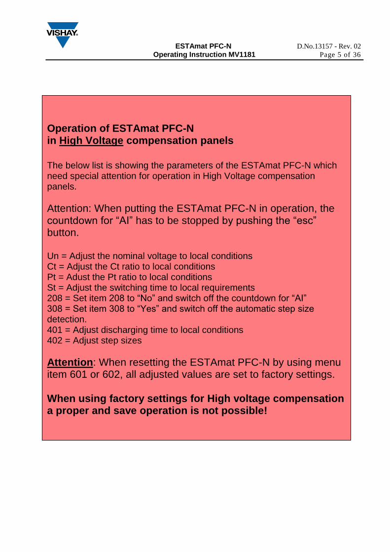
Operation of ESTAmat PFC-N in High Voltage compensation panels
The below list is showing the parameters of the ESTAmat PFC-N which need special attention for operation in High Voltage compensation panels.
Attention: When putting the ESTAmat PFC-N in operation, the countdown for “AI” has to be stopped by pushing the “esc” button. Un = Adjust the nominal voltage to local conditions Ct = Adjust the Ct ratio to local conditions Pt = Adust the Pt ratio to local conditions St = Adjust the switching time to local requirements 208 = Set item 208 to “No” and switch off the countdown for “AI” 308 = Set item 308 to “Yes” and switch off the automatic step size detection. 401 = Adjust discharging time to local conditions 402 = Adjust step sizes
Attention: When resetting the ESTAmat PFC-N by using menu item 601 or 602, all adjusted values are set to factory settings. When using factory settings for High voltage compensation a proper and save operation is not possible!
ESTAmat PFC-N D.No.13157 - Rev. 02
Operating Instruction MV1181 Page 6 of 36
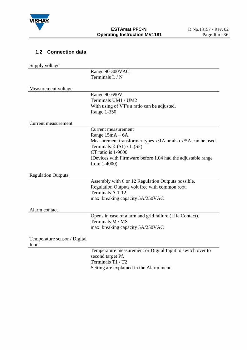
1.2 Connection data
Supply voltage
Measurement voltage
Range 90-300VAC.
Terminals L / N
Range 90-690V.
Terminals UM1 / UM2
With using of VT's a ratio can be adjusted.
Range 1-350
Current measurement
Current measurement
Range 15mA – 6A,
Measurement transformer types x/1A or also x/5A can be used.
Terminals K (S1) / L (S2)
CT ratio is 1-9600
(Devices with Firmware before 1.04 had the adjustable range
from 1-4000)
Regulation Outputs
Assembly with 6 or 12 Regulation Outputs possible.
Regulation Outputs volt free with common root.
Terminals A 1-12
max. breaking capacity 5A/250VAC
Alarm contact
Opens in case of alarm and grid failure (Life Contact).
Terminals M / MS
max. breaking capacity 5A/250VAC
Temperature sensor / Digital
Input
Temperature measurement or Digital Input to switch over to
second target Pf.
Terminals T1 / T2
Setting are explained in the Alarm menu.
ESTAmat PFC-N D.No.13157 - Rev. 02
Operating Instruction MV1181 Page 7 of 36
2 COMMISSIONING
2.1 ESTAmat PFC-N is parameterized:
After the supply voltage is applied, in ESTAmat PFC-N starts a countdown with 90 sec. Cancel the
countdown by pressing the (esc) button or expire the countdown. After expiring the countdown,
starts the adjusted discharge time for the capacitors (default 75 sec.). Only then the regulations
starts with preset parameters.
2.2 ESTAmat PFC-N is not parameterized:
During the countdown, the auto-initialization can be start by pushing the ( ) button. The
regulator determine which control outputs are not used and blocks them. A wrong connection of
voltage and current will be determined and corrected. After expiration of the auto-initialization, the
controller start the regulation and recognize automatically the step sizes of the capacitors. Settings
of c/K value and the switching sequence is not required.
When mains conditions are not suitable for auto-initialization, it will be interrupted. The controller
shows the message
„Ai Abrt“. If multiple repetition do not lead to any result, the following chapters shall be
considered.
Display „Auto“: Indication „Auto“ shows that the control is working. If „Auto“ is not displayed
then control function is stopped. This can happen for the following Reasons: manual mode is active,
control function is switched off, temperature is to high, measured current is less than 15mA, voltage
or the harmonic content is outside the admissible range.
Over-and undervoltage monitoring: The ESTAmat PFC-N is equipped with an over and
undervoltage monitoring. The admissible voltage range refers to the adjusted nominal voltage. If the
measured voltage is outside of the admissible range the message U Alarm appears. Then the setting
of nominal voltage has to be adapt to local ratings. The nominal voltage is independent of the
connection always the line voltage.
Activation of the measured value display: see chapter 4.1
ESTAmat PFC-N D.No.13157 - Rev. 02
Operating Instruction MV1181 Page 8 of 36
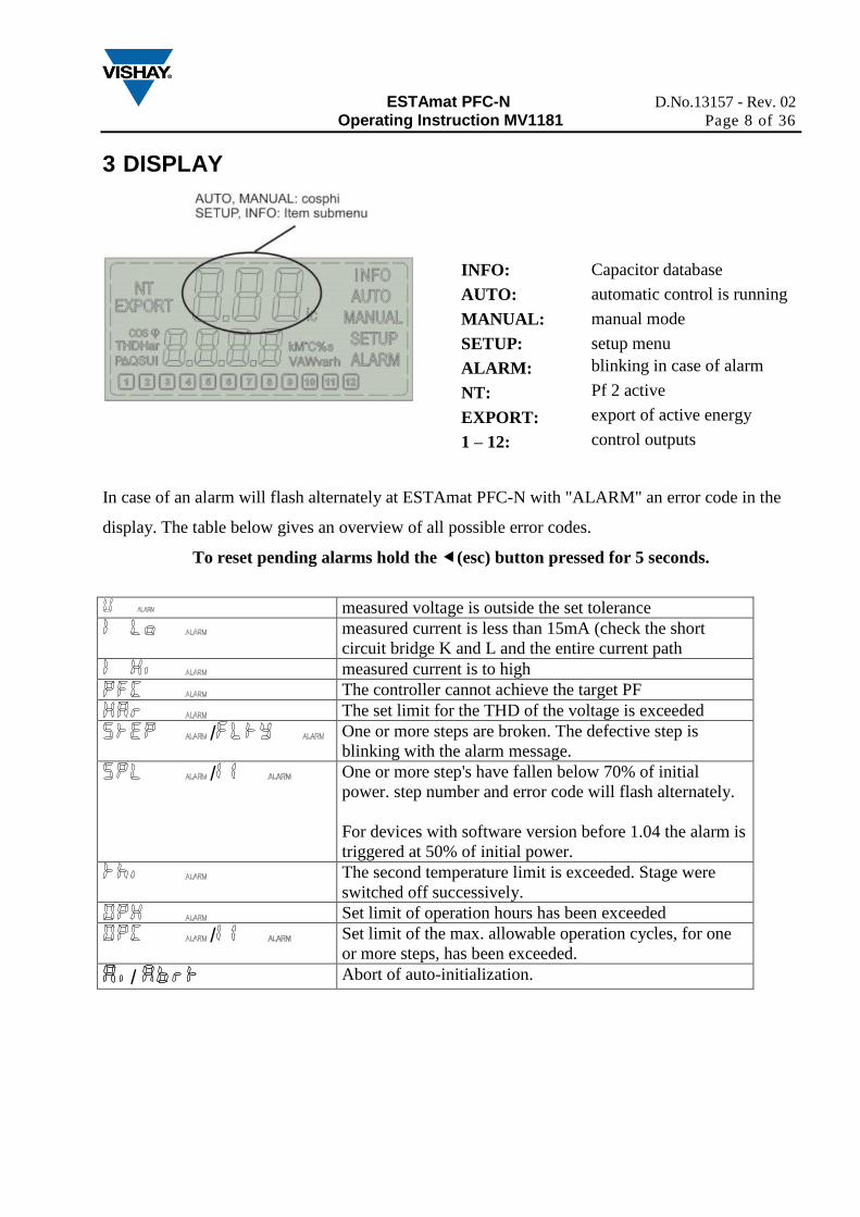
3 DISPLAY
In case of an alarm will flash alternately at ESTAmat PFC-N with "ALARM" an error code in the
display. The table below gives an overview of all possible error codes.
To reset pending alarms hold the (esc) button pressed for 5 seconds.
measured voltage is outside the set tolerance
measured current is less than 15mA (check the short
circuit bridge K and L and the entire current path
measured current is to high
The controller cannot achieve the target PF
The set limit for the THD of the voltage is exceeded
/ One or more steps are broken. The defective step is
blinking with the alarm message.
/ One or more step's have fallen below 70% of initial
power. step number and error code will flash alternately.
For devices with software version before 1.04 the alarm is
triggered at 50% of initial power.
The second temperature limit is exceeded. Stage were
switched off successively.
Set limit of operation hours has been exceeded
/ Set limit of the max. allowable operation cycles, for one
or more steps, has been exceeded.
/ Abort of auto-initialization.
INFO: Capacitor database
AUTO: automatic control is running
MANUAL: manual mode
SETUP: setup menu
ALARM: blinking in case of alarm
NT: Pf 2 active
EXPORT: export of active energy
1 – 12: control outputs
ESTAmat PFC-N D.No.13157 - Rev. 02
Operating Instruction MV1181 Page 9 of 36
4 MENU ESTAmat PFC-N
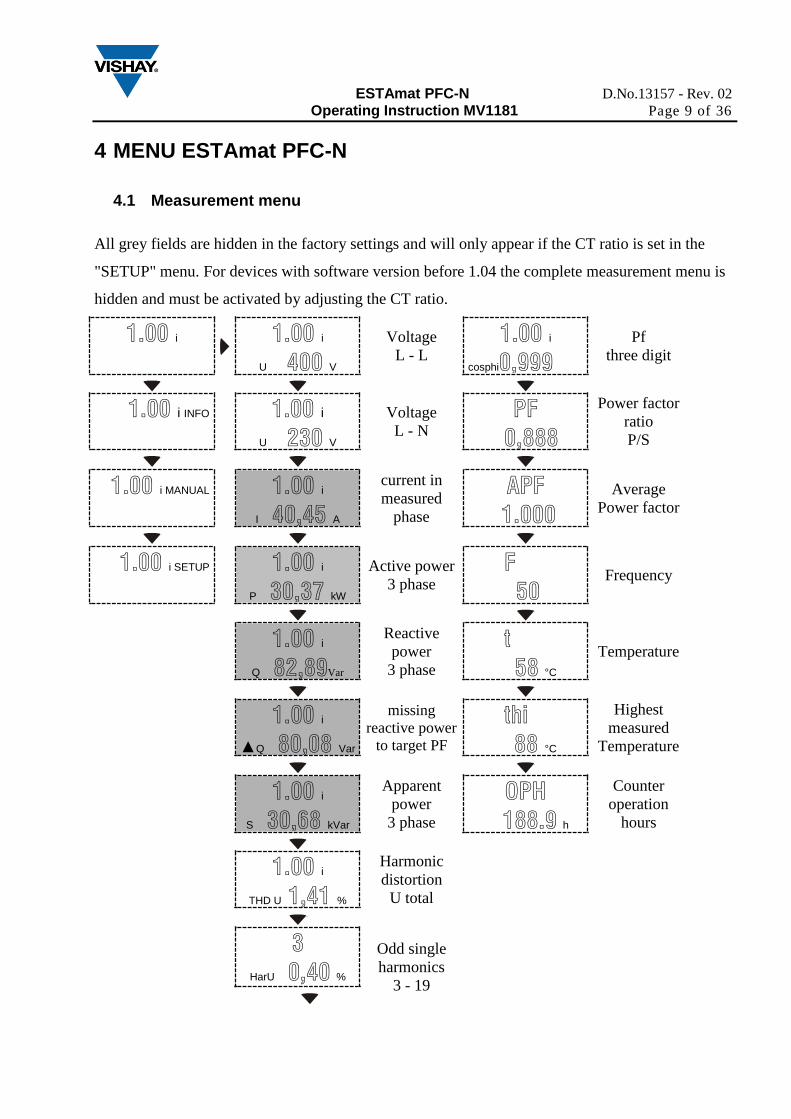
4.1 Measurement menu
All grey fields are hidden in the factory settings and will only appear if the CT ratio is set in the
"SETUP" menu. For devices with software version before 1.04 the complete measurement menu is
hidden and must be activated by adjusting the CT ratio.
1.00 i
1.00 i
U 400 V
Voltage
L - L
1.00 i
cosphi0,999
Pf
three digit
1.00 i INFO
1.00 i
U 230 V
Voltage
L - N
PF
0,888
Power factor
ratio
P/S
1.00 i MANUAL
1.00 i
I 40,45 A
current in
measured
phase
APF
1.000
Average
Power factor
1.00 i SETUP
1.00 i
P 30,37 kW
Active power
3 phase
F
50
Frequency
1.00 i
Q 82,89Var
Reactive
power
3 phase
t
58 °C
Temperature
1.00 i
▲Q 80,08 Var
missing
reactive power
to target PF
thi
88 °C
Highest
measured
Temperature
1.00 i
S 30,68 kVar
Apparent
power
3 phase
OPH
188.9 h
Counter
operation
hours
1.00 i
THD U 1,41 %
Harmonic
distortion
U total
3
HarU 0,40 %
Odd single
harmonics
3 - 19
ESTAmat PFC-N D.No.13157 - Rev. 02
Operating Instruction MV1181 Page 10 of 36
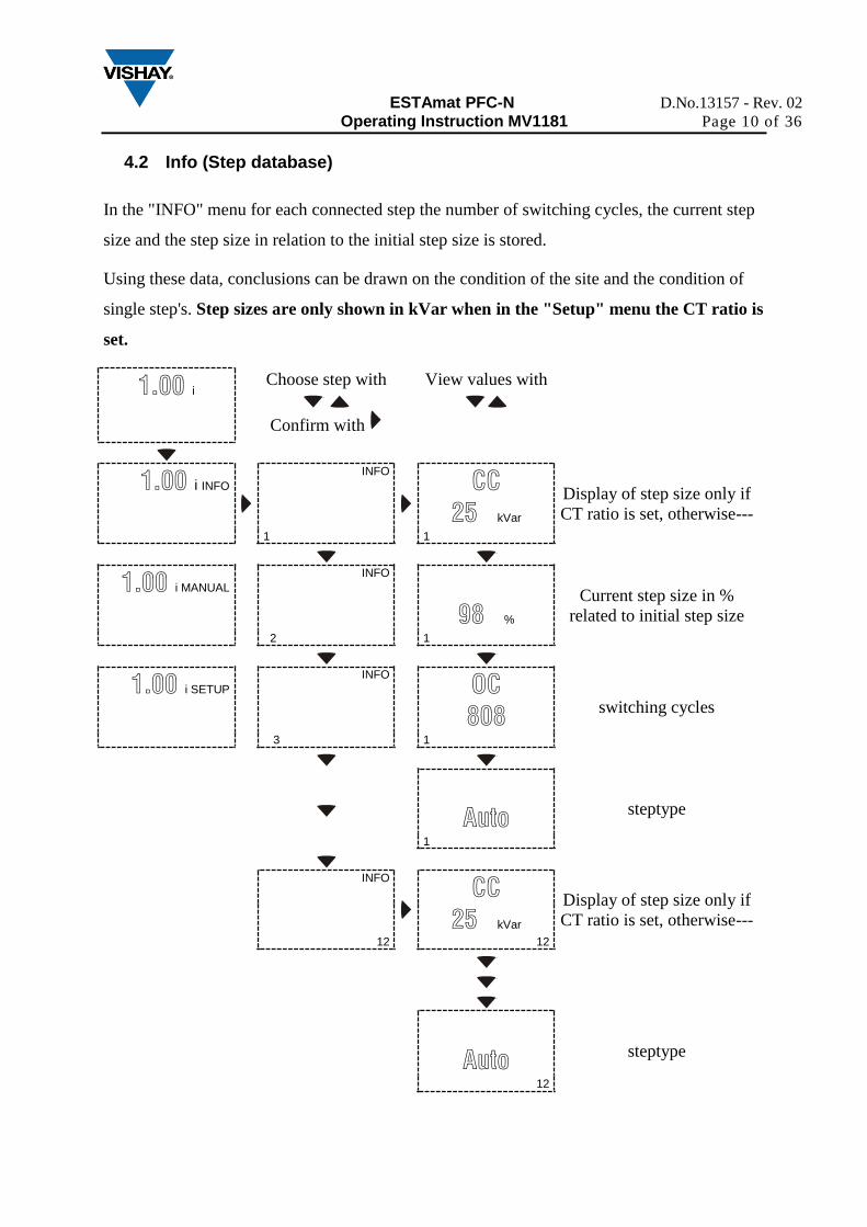
4.2 Info (Step database)
In the "INFO" menu for each connected step the number of switching cycles, the current step
size and the step size in relation to the initial step size is stored.
Using these data, conclusions can be drawn on the condition of the site and the condition of
single step's. Step sizes are only shown in kVar when in the "Setup" menu the CT ratio is
set.
1.00 i
Choose step with
Confirm with
View values with
1.00 i INFO
INFO
CC
25 kVar
Display of step size only if
CT ratio is set, otherwise---
1 1
1.00 i MANUAL
INFO
98 %
Current step size in %
related to initial step size
2 1
1.00 i SETUP
INFO
OC
808 switching cycles
3 1
Auto steptype
1
INFO
CC
25 kVar 12
Display of step size only if
CT ratio is set, otherwise---
12
Auto steptype
12
ESTAmat PFC-N D.No.13157 - Rev. 02
Operating Instruction MV1181 Page 11 of 36
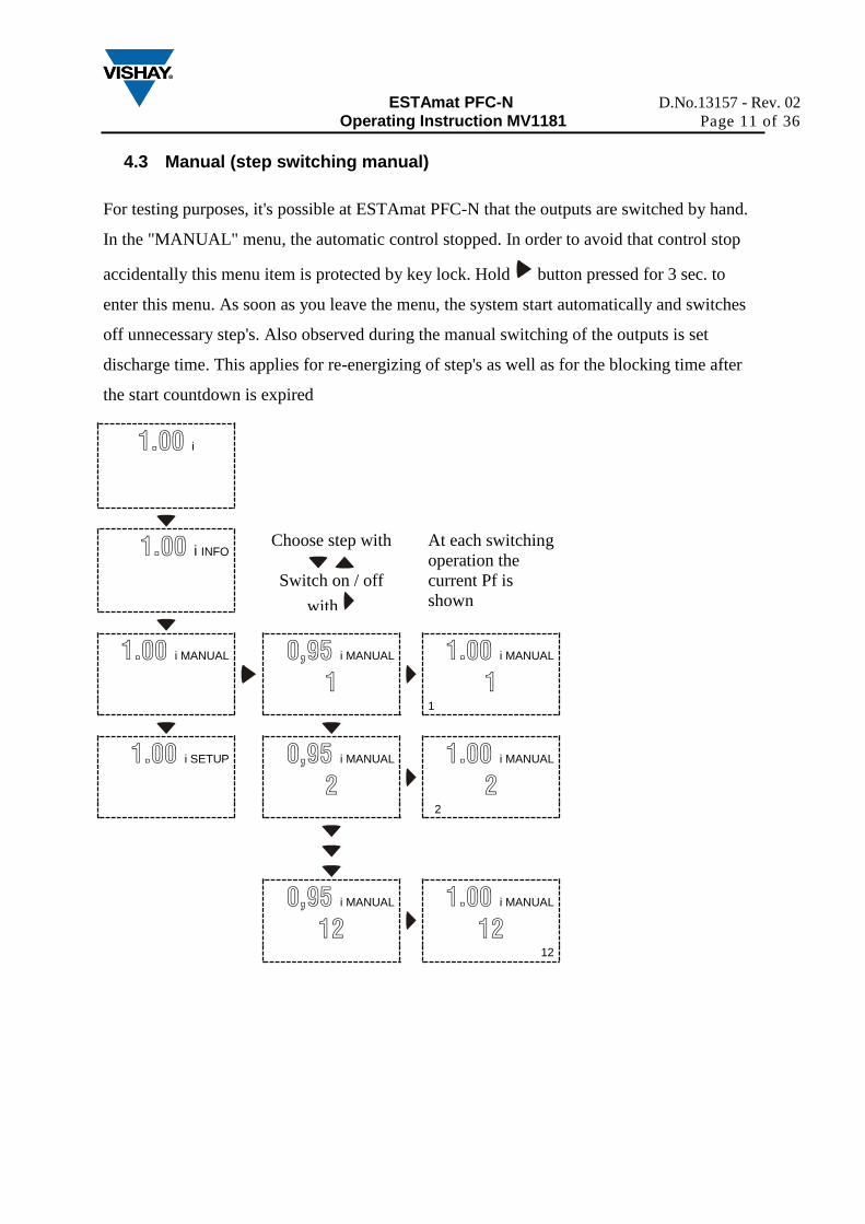
4.3 Manual (step switching manual)
For testing purposes, it's possible at ESTAmat PFC-N that the outputs are switched by hand.
In the "MANUAL" menu, the automatic control stopped. In order to avoid that control stop
accidentally this menu item is protected by key lock. Hold button pressed for 3 sec. to
enter this menu. As soon as you leave the menu, the system start automatically and switches
off unnecessary step's. Also observed during the manual switching of the outputs is set
discharge time. This applies for re-energizing of step's as well as for the blocking time after
the start countdown is expired
1.00 i
1.00 i INFO
Choose step with
Switch on / off
with
At each switching
operation the
current Pf is
shown
1.00 i MANUAL
0,95 i MANUAL
1
1.00 i MANUAL
1
1
1.00 i SETUP
0,95 i MANUAL
2
1.00 i MANUAL
2
2
0,95 i MANUAL
12
1.00 i MANUAL
12
12
ESTAmat PFC-N D.No.13157 - Rev. 02
Operating Instruction MV1181 Page 12 of 36
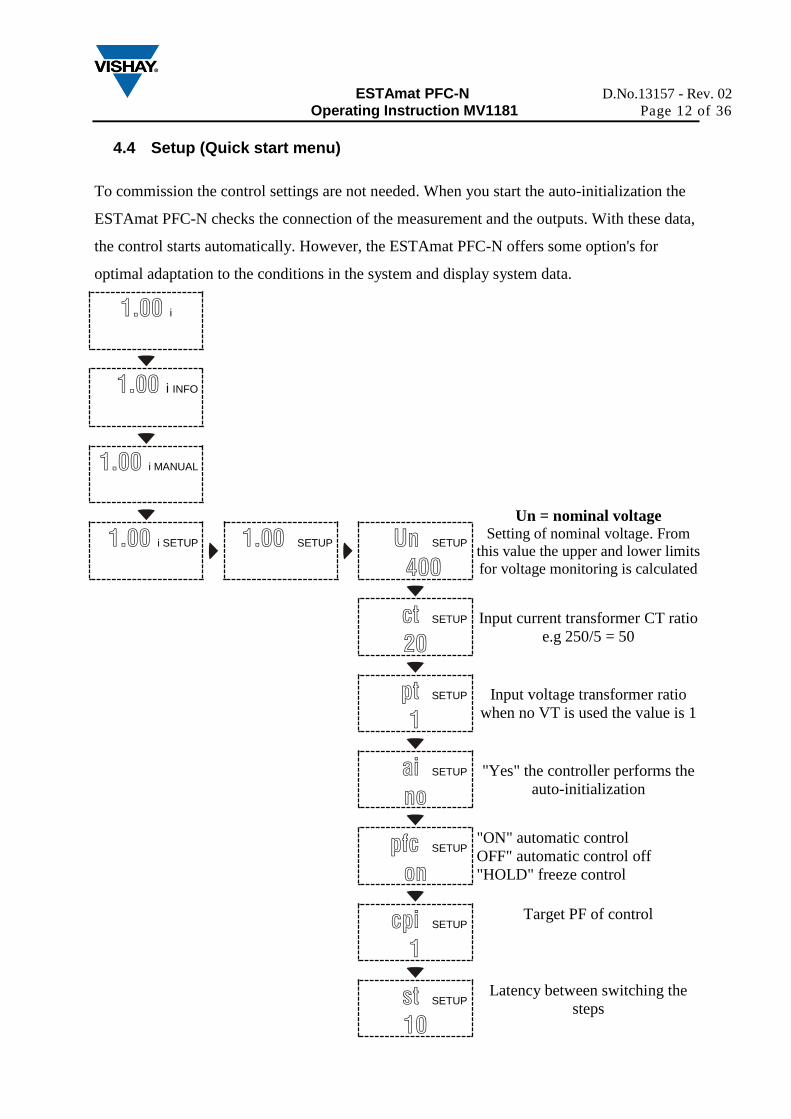
4.4 Setup (Quick start menu)
To commission the control settings are not needed. When you start the auto-initialization the
ESTAmat PFC-N checks the connection of the measurement and the outputs. With these data,
the control starts automatically. However, the ESTAmat PFC-N offers some option's for
optimal adaptation to the conditions in the system and display system data.
1.00 i
1.00 i INFO
1.00 i MANUAL
Un = nominal voltage Setting of nominal voltage. From
this value the upper and lower limits
for voltage monitoring is calculated
1.00 i SETUP
1.00 SETUP
Un SETUP
400
ct SETUP
20
Input current transformer CT ratio
e.g 250/5 = 50
pt SETUP
1
Input voltage transformer ratio
when no VT is used the value is 1
ai SETUP
no
"Yes" the controller performs the
auto-initialization
pfc SETUP
on
"ON" automatic control
OFF" automatic control off
"HOLD" freeze control
cpi SETUP
1
Target PF of control
st SETUP
10
Latency between switching the
steps
ESTAmat PFC-N D.No.13157 - Rev. 02
Operating Instruction MV1181 Page 13 of 36
5 EXPERT MENU ESTAmat PFC-N
To open the expert menu of ESTAmat PFC-N, choose menu item "SETUP" and hold ( )
button until "100" appears. By using the buttons the submenus can be selected. The
expert menu of ESTAmat PFC-N is divided into six groups, where the menu items are
logically grouped together. The following groups exist:
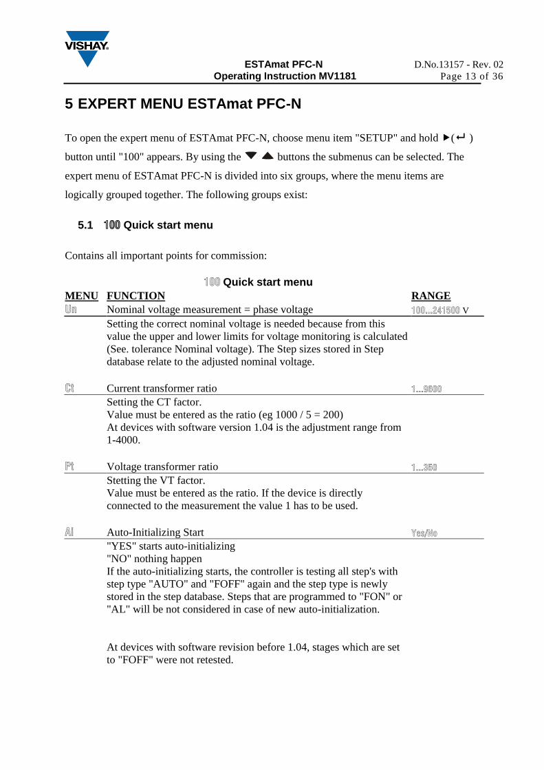
5.1 100 Quick start menu
Contains all important points for commission:
100 Quick start menu
MENU FUNCTION RANGE
Un Nominal voltage measurement = phase voltage 100...241500 V
Setting the correct nominal voltage is needed because from this
value the upper and lower limits for voltage monitoring is calculated
(See. tolerance Nominal voltage). The Step sizes stored in Step
database relate to the adjusted nominal voltage.
Ct Current transformer ratio 1...9600
Setting the CT factor.
Value must be entered as the ratio (eg 1000 / 5 = 200)
At devices with software version 1.04 is the adjustment range from
1-4000.
Pt Voltage transformer ratio 1...350
Stetting the VT factor.
Value must be entered as the ratio. If the device is directly
connected to the measurement the value 1 has to be used.
Ai Auto-Initializing Start Yes/No
"YES" starts auto-initializing
"NO" nothing happen
If the auto-initializing starts, the controller is testing all step's with
step type "AUTO" and "FOFF" again and the step type is newly
stored in the step database. Steps that are programmed to "FON" or
"AL" will be not considered in case of new auto-initialization.
At devices with software revision before 1.04, stages which are set
to "FOFF" were not retested.
ESTAmat PFC-N D.No.13157 - Rev. 02
Operating Instruction MV1181 Page 14 of 36
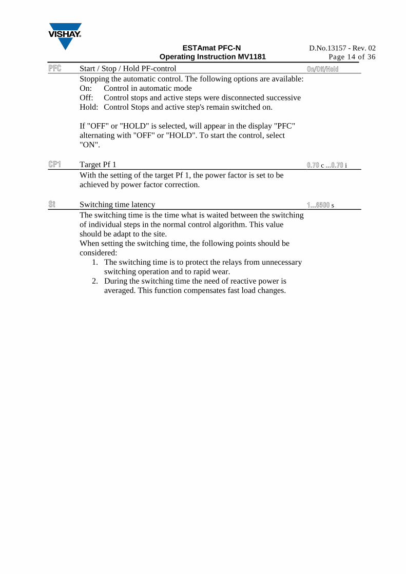
PFC Start / Stop / Hold PF-control On/Off/Hold
Stopping the automatic control. The following options are available:
On: Control in automatic mode
Off: Control stops and active steps were disconnected successive
Hold: Control Stops and active step's remain switched on.
If "OFF" or "HOLD" is selected, will appear in the display "PFC"
alternating with "OFF" or "HOLD". To start the control, select
"ON".
CP1 Target Pf 1 0.70 c ...0.70 i
With the setting of the target Pf 1, the power factor is set to be
achieved by power factor correction.
St Switching time latency 1...6500 s
The switching time is the time what is waited between the switching
of individual steps in the normal control algorithm. This value
should be adapt to the site.
When setting the switching time, the following points should be
considered:
1. The switching time is to protect the relays from unnecessary
switching operation and to rapid wear.
2. During the switching time the need of reactive power is
averaged. This function compensates fast load changes.

ESTAmat PFC-N D.No.13157 - Rev. 02
Operating Instruction MV1181 Page 15 of 36
5.2 200 Measurement settings
Contains settings to adapt the measurement of the ESTAmat PFC-N to the surrounding
network conditions.
200 Measurement settings
MENU FUNCTION RANGE
201 Nominal voltage measurement = phase voltage 100...241500 V
Setting the correct nominal voltage is needed because from this
value the upper and lower limits for voltage monitoring is calculated
(See. Nominal voltage tolerance range). The Step sizes stored in
Step database relate to the adjusted nominal voltage.
202 Current transformer ratio 1...9600
Setting the CT factor.
Value must be entered as the ratio (e.g. 1000 / 5 = 200)
At devices with software version 1.04 is the adjustment range from
1-4000.
203 Voltage transformer ratio 1...350
Stetting the VT factor.
Value must be entered as the ratio. If the device is directly
connected to the measurement the value 1 has to be used.
204 Nominal voltage tolerance range 0...100 %
The setting of this value is in percent related to the nominal voltage.
By means of the set value, the upper and lower limits of the
permissible voltage range are calculated. e.g. 10% at 400V nominal
voltage is a permissible range from 360V to 440V.
205 Connection voltage measurement Yes/No
"YES" voltage measurement L-L
"NO" voltage measurement L-N
Based on the set voltage, the controller automatically detects the
voltage for both types of connection (LL and LN). If these are
within the set tolerance (factory setting +/- 10%) the controller shall
determine the voltage measurement. This cannot be changed by
hand.
If the measured voltage is outside this tolerance, the measurement
can be adjusted by hand.
ESTAmat PFC-N D.No.13157 - Rev. 02
Operating Instruction MV1181 Page 16 of 36
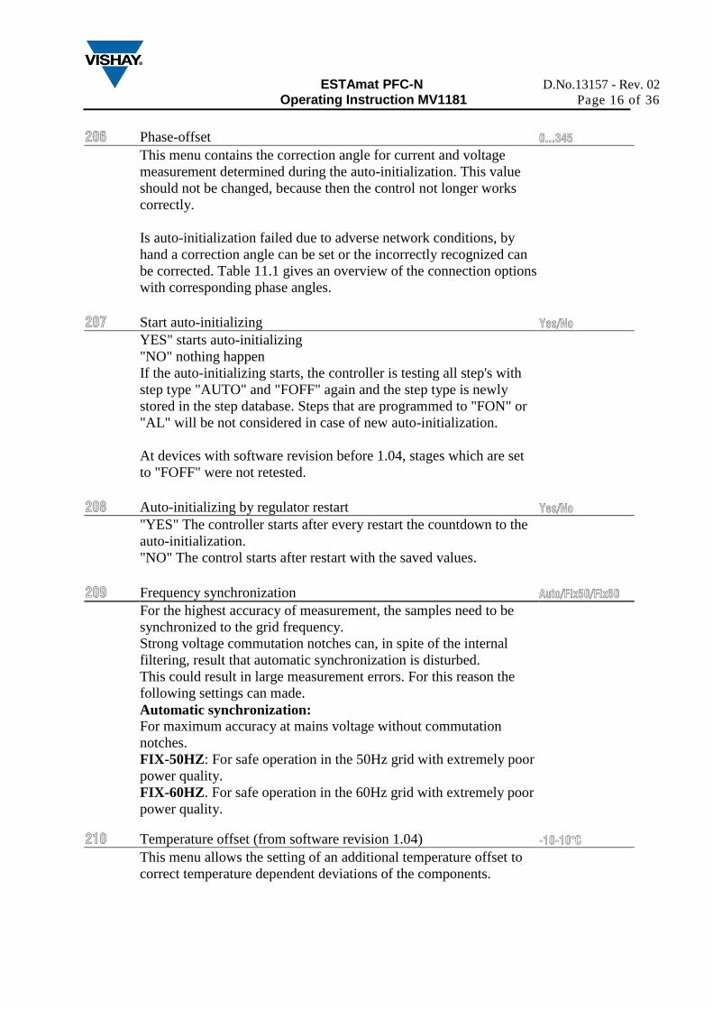
206 Phase-offset 0...345
This menu contains the correction angle for current and voltage
measurement determined during the auto-initialization. This value
should not be changed, because then the control not longer works
correctly.
Is auto-initialization failed due to adverse network conditions, by
hand a correction angle can be set or the incorrectly recognized can
be corrected. Table 11.1 gives an overview of the connection options
with corresponding phase angles.
207 Start auto-initializing Yes/No
YES" starts auto-initializing
"NO" nothing happen
If the auto-initializing starts, the controller is testing all step's with
step type "AUTO" and "FOFF" again and the step type is newly
stored in the step database. Steps that are programmed to "FON" or
"AL" will be not considered in case of new auto-initialization.
At devices with software revision before 1.04, stages which are set
to "FOFF" were not retested.
208 Auto-initializing by regulator restart Yes/No
"YES" The controller starts after every restart the countdown to the
auto-initialization.
"NO" The control starts after restart with the saved values.
209 Frequency synchronization Auto/Fix50/Fix60
For the highest accuracy of measurement, the samples need to be
synchronized to the grid frequency.
Strong voltage commutation notches can, in spite of the internal
filtering, result that automatic synchronization is disturbed.
This could result in large measurement errors. For this reason the
following settings can made.
Automatic synchronization:
For maximum accuracy at mains voltage without commutation
notches.
FIX-50HZ: For safe operation in the 50Hz grid with extremely poor
power quality.
FIX-60HZ. For safe operation in the 60Hz grid with extremely poor
power quality.
210 Temperature offset (from software revision 1.04)
-10-10°C
This menu allows the setting of an additional temperature offset to
correct temperature dependent deviations of the components.
ESTAmat PFC-N D.No.13157 - Rev. 02
Operating Instruction MV1181 Page 17 of 36
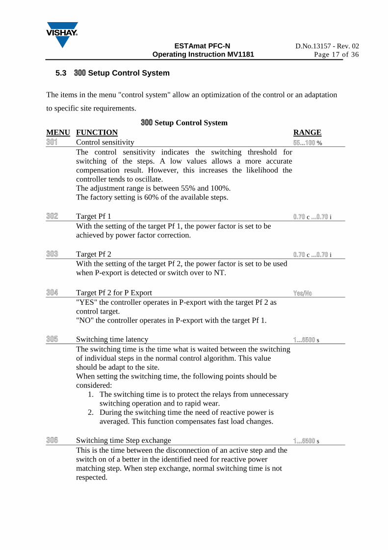
5.3 300 Setup Control System
The items in the menu "control system" allow an optimization of the control or an adaptation
to specific site requirements.
300 Setup Control System
MENU FUNCTION RANGE
301 Control sensitivity 55...100 %
The control sensitivity indicates the switching threshold for
switching of the steps. A low values allows a more accurate
compensation result. However, this increases the likelihood the
controller tends to oscillate.
The adjustment range is between 55% and 100%.
The factory setting is 60% of the available steps.
302 Target Pf 1 0.70 c ...0.70 i
With the setting of the target Pf 1, the power factor is set to be
achieved by power factor correction.
303 Target Pf 2 0.70 c ...0.70 i
With the setting of the target Pf 2, the power factor is set to be used
when P-export is detected or switch over to NT.
304 Target Pf 2 for P Export Yes/No
"YES" the controller operates in P-export with the target Pf 2 as
control target.
"NO" the controller operates in P-export with the target Pf 1.
305 Switching time latency 1...6500 s
The switching time is the time what is waited between the switching
of individual steps in the normal control algorithm. This value
should be adapt to the site.
When setting the switching time, the following points should be
considered:
1. The switching time is to protect the relays from unnecessary
switching operation and to rapid wear.
2. During the switching time the need of reactive power is
averaged. This function compensates fast load changes.
306 Switching time Step exchange 1...6500 s
This is the time between the disconnection of an active step and the
switch on of a better in the identified need for reactive power
matching step. When step exchange, normal switching time is not
respected.
ESTAmat PFC-N D.No.13157 - Rev. 02
Operating Instruction MV1181 Page 18 of 36
307 Activate Step exchange Yes/No
"YES" for an optimal compensation result, the controller can switch
off active steps and replace them with more suitable steps.
"NO" This function is deactivated.
This function is useful when different step sizes are available. If all
available step have the same step size, then this feature should be
disabled otherwise is may lead to unnecessary switching cycles.
308 Step recognition "OFF" Yes/No
"YES": Step sizes have to be programmed by hand. The step sizes
have to be programmed by hand if:
a) there is in the system quickly changing loads and problems
with the automatic step size detection occurs.
b) the automatic detection of defective steps is not desired.
c) the contactors have a delay of more than 200msec.
"NO" Step sizes are automatically determined during operation and
losses of step sizes were tracked and considered at the control.
309 Blocking of defective capacitors Yes/No
"YES" If a step is switched in three times without measurable
network reaction, the controller is blocking the step and doesn't use
it for the control.
Is a Step recognized to be defective, blinks in the display the
corresponding output and in the step database and menu "403" it's
displayed as step type "flty".
"NO" Steps are connected even if no network reaction is
measurable. This results unnecessary switching cycles.
Steps that are stored as defective will be tested every 24 hours or
after the controller is restarted.
310 Start / Stop / Hold PF-control On/Off/Hold
Stopping the automatic control. The following options are available:
On: Control in automatic mode
Off: Control stops and active steps were disconnected successive
Hold: Control Stops and active step's remain switched on.
If "OFF" or "HOLD" is selected, will appear in the display "PFC"
alternating with "OFF" or "HOLD". To start the control, select
"ON".
ESTAmat PFC-N D.No.13157 - Rev. 02
Operating Instruction MV1181 Page 19 of 36
311 Control algorithm 1/2/3/4
1. Automatic: The controller operates on the "Best Fit"
principle. This means the controller compares before each
switching operation, all in the step database stored step sizes
with the identified need for reactive power and choose
always the step which is the closest to the control target. If
the controller has several equal steps available, the number
of switching cycles automatically distributed to these steps.
2. LIFO: „Last In, First Out“ Switch on the outputs is always
done in the switching sequence 1-2-3-4-max. The switch off
is in the switching sequence been turned upside max-4-3-2-1.
3. Kombifilter: Special algorithm for combined filter banks.
The controller operates on the "best fit" principle as in
automatic mode. Unlike to automatic mode the controller is
connecting always at least the same or more capacitance
which is connected to the odd numbered outputs with the
even numbered outputs. If the controller has several equal
steps available, the number of switching cycles automatically
distributed to these steps.
4. Progressive: The controller switches if required, several
steps in sequence with a shorter switching time. From
software 1.04, the controller uses independently of the set
switching time always 1 sec. as switching time. Furthermore,
the automatic step size detection is disabled and the step
sizes need to enter by hand. The input of the step sizes
should be as accurate as possible, because the regulator
would otherwise tend to oscillate. Leaving the "Progressive"
algorithm and use a different algorithm, the set switching
time is used the step size detection is re-enabled.
312 Offset reactive power Ct*Pt*7000
The set here offset reactive power is always added to the measured
reactive power. This means that the system can be capacitive, but
measurement of the utility records the required Pf. The set offset
reactive power also goes into the calculation of ▲Q, Pf, apparent
power, current and active power. The max. offset reactive power
that can be entered is calculated from the set current and voltage
transformer ratios.
313 Switching time asymmetrical -127...127
The set factor multiplies the selected switching time in the
capacitive direction (fast switch on of steps and slow switch off). If
this factor is set with – as sign the function works vice versa.
Factory setting "1" (means symmetrical switching times for both
directions)

ESTAmat PFC-N D.No.13157 - Rev. 02
Operating Instruction MV1181 Page 20 of 36
314 Switch-off in leading condition Yes/No
"YES" As soon as a capacitive condition is recognized, the
controller switches off without keeping the switching time, the
necessary step power in order to prevent leading network conditions.
"NO" The controller works only with the set target Pf.
ESTAmat PFC-N D.No.13157 - Rev. 02
Operating Instruction MV1181 Page 21 of 36
5.4 400 Setup Step Database
In the step database, all settings and data are combined which are required to adjust and adapt
the steps.
400 Setup Step Database
MENU FUNCTION RANGE
401 Discharge time 0,5...1200 s
The discharge time is defined once and is valid for all steps. The
discharge time is a lockout time, which expires after switching off a
step. Until this time has not expired, the corresponding step for the
regulation is not available. The discharge time should be adapted to
the discharge unit of the capacitor.
402 Capacitor size Ct*Pt*7000
If the automatic size-detection is disabled, then it is necessary to
enter the nominal step size. The input is done in var and is related to
nominal voltage. The adjustment must be done separately for each
output.
Warning: Before the step size is set, must be set the correct current
and voltage transformer ratio since the max. possible steps size is
limited by these ratios. After an step size has been entered, should
the current and voltage transformers ratio will not changed because
these changes affect the set step size. Hand-programmed "normal"
steps will be overwritten by the automatic step size detection
403 Type of output Auto/Al/FOn/FOff
For each step the function can be set separately. The following
functions can be selected:
Auto = Step is used in the normal control algorithm
Alarm = If the set temperature limit 1 is exceeded this step is
switched as fan output.
Fon = Step is permanently switched on (Step is still
monitored and shut down in critical situations)
Foff = Step is permanently switched off
flty = Step was switched three times without success and is
not longer used for the control. Defective steps flashing in
the step indication.
If defective steps should not be locked, you must disable this
function under the menu item "309".
Steps which are identified as defective will be tested again by the
controller every 24 hours or after a restart.

ESTAmat PFC-N D.No.13157 - Rev. 02
Operating Instruction MV1181 Page 22 of 36
404 Switching cycles 0...262000
The ESTAmat PFC-N is counting the operations of the switching
outputs and displays them in the "Info" menu.
After a contactor has been exchanged, the switching cycles can be
set to "0" in this menu.
ESTAmat PFC-N D.No.13157 - Rev. 02
Operating Instruction MV1181 Page 23 of 36
5.5 500 Setup Alarm
The alarm menu of ESTAmat PFC-N. Here, all the alarms and monitoring functions can be
activated and the limits configured.
500 Setup Alarm
MENU FUNCTION RANGE
501 Reset Alarm manually Yes/No
"YES" Alarms (display and alarm relays) must be reset manually.
To reset upcoming alarms, hold the (esc) button pressed for 5
seconds. "NO" As soon as the alarm condition is no longer valid, the alarms
drop out.
502 THD U Alarm Yes/No
"YES" The set THD threshold under menu "503" is monitored.
Exceeding the set threshold will open the alarm contact and the
display will show the message " ".
"NO" THD is not monitored.
503 THD U Threshold 1...200 %
Input of the threshold for THD monitoring.
504 THD U > Threshold = disconnect steps Yes/No
"YES" Exceeding the set threshold for THD will switch off all
active steps successive.
Warning: Steps are only switched off when it is set at point 502
to "YES".
"NO" Exceeding the set threshold follows no action.
505 Latency time before triggers THD U and Temperature threshold 2 1...255 s
Latency time after exceeding the threshold for THD U or
temperature threshold 2.
506 Freeze control if I == 0 Yes/No
"YES" The measuring current drops below 15mA freezes the
control. All active steps remains switched on.
NO" Measuring current falls below 15mA, the controller shuts down
all active steps successive.
507 Service Alarm Yes/No
"YES" the alarm contact opens when the max set switching cycles
for one or more steps have been exceeded or if the set threshold for
operation hours are reached.
ESTAmat PFC-N D.No.13157 - Rev. 02
Operating Instruction MV1181 Page 24 of 36
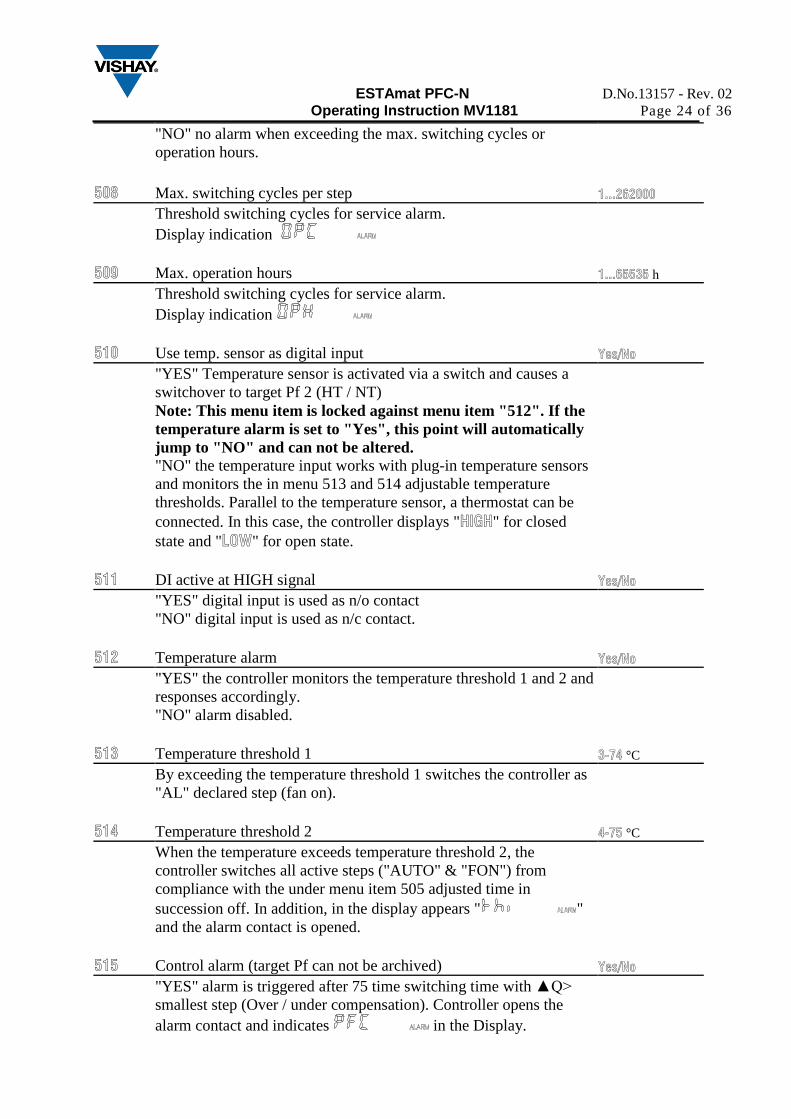
"NO" no alarm when exceeding the max. switching cycles or
operation hours.
508 Max. switching cycles per step 1...262000
Threshold switching cycles for service alarm.
Display indication
509 Max. operation hours 1...65535 h
Threshold switching cycles for service alarm.
Display indication
510 Use temp. sensor as digital input Yes/No
"YES" Temperature sensor is activated via a switch and causes a
switchover to target Pf 2 (HT / NT)
Note: This menu item is locked against menu item "512". If the
temperature alarm is set to "Yes", this point will automatically
jump to "NO" and can not be altered.
"NO" the temperature input works with plug-in temperature sensors
and monitors the in menu 513 and 514 adjustable temperature
thresholds. Parallel to the temperature sensor, a thermostat can be
connected. In this case, the controller displays "HIGH" for closed
state and "LOW" for open state.
511 DI active at HIGH signal Yes/No
"YES" digital input is used as n/o contact
"NO" digital input is used as n/c contact.
512 Temperature alarm Yes/No
"YES" the controller monitors the temperature threshold 1 and 2 and
responses accordingly.
"NO" alarm disabled.
513 Temperature threshold 1 3-74 °C
By exceeding the temperature threshold 1 switches the controller as
"AL" declared step (fan on).
514 Temperature threshold 2 4-75 °C
When the temperature exceeds temperature threshold 2, the
controller switches all active steps ("AUTO" & "FON") from
compliance with the under menu item 505 adjusted time in
succession off. In addition, in the display appears " "
and the alarm contact is opened.
515 Control alarm (target Pf can not be archived) Yes/No
"YES" alarm is triggered after 75 time switching time with ▲Q>
smallest step (Over / under compensation). Controller opens the
alarm contact and indicates in the Display.
ESTAmat PFC-N D.No.13157 - Rev. 02
Operating Instruction MV1181 Page 25 of 36
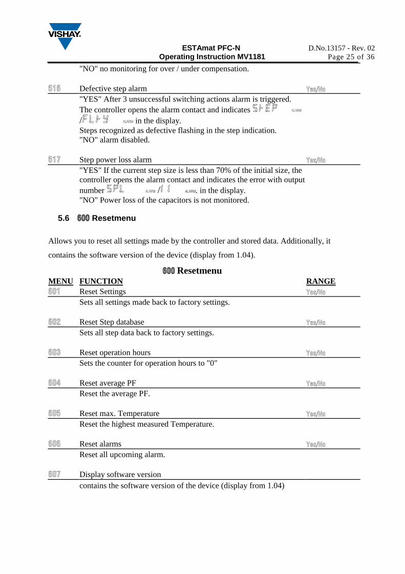
"NO" no monitoring for over / under compensation.
516 Defective step alarm Yes/No
"YES" After 3 unsuccessful switching actions alarm is triggered.
The controller opens the alarm contact and indicates
/ in the display.
Steps recognized as defective flashing in the step indication.
"NO" alarm disabled.
517 Step power loss alarm Yes/No
"YES" If the current step size is less than 70% of the initial size, the
controller opens the alarm contact and indicates the error with output
number / . in the display.
"NO" Power loss of the capacitors is not monitored.
5.6 600 Resetmenu
Allows you to reset all settings made by the controller and stored data. Additionally, it
contains the software version of the device (display from 1.04).
600 Resetmenu
MENU FUNCTION RANGE
601 Reset Settings Yes/No
Sets all settings made back to factory settings.
602 Reset Step database Yes/No
Sets all step data back to factory settings.
603 Reset operation hours Yes/No
Sets the counter for operation hours to "0"
604 Reset average PF Yes/No
Reset the average PF.
605 Reset max. Temperature Yes/No
Reset the highest measured Temperature.
606 Reset alarms Yes/No
Reset all upcoming alarm.
607 Display software version
contains the software version of the device (display from 1.04)
ESTAmat PFC-N D.No.13157 - Rev. 02
Operating Instruction MV1181 Page 26 of 36
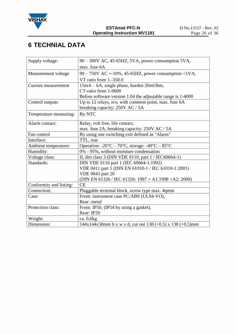
6 TECHNIAL DATA
Supply voltage: 90 – 300V AC, 45-65HZ, 5VA, power consumption 5VA,
max. fuse 6A
Measurement voltage 90 – 750V AC +-10%, 45-65HZ, power consumption <1VA,
VT ratio from 1.-350.0
Current measurement 15mA – 6A, single phase, burden 20mOhm,
CT-ratio from 1-9600
Before software version 1.04 the adjustable range is 1-4000
Control outputs Up to 12 relays, n/o, with common point, max. fuse 6A
breaking capacity: 250V AC / 5A
Temperature measuring: By NTC
Alarm contact: Relay, volt free, life contact,
max. fuse 2A, breaking capacity: 250V AC / 5A
Fan control By using one switching exit defined as "Alarm"
Interface: TTL, rear
Ambient temperature: Operation: -20°C – 70°C, storage: -40°C – 85°C
Humidity: 0% - 95%, without moisture condensation
Voltage class: II, dirt class 3 (DIN VDE 0110, part 1 / IEC60664-1)
Standards: DIN VDE 0110 part 1 (IEC 60664-1:1992)
VDE 0411 part 1 (DIN EN 61010-1 / IEC 61010-1:2001)
VDE 0843 part 20
(DIN EN 61326 / IEC 61326: 1997 + A1:1998 +A2: 2000)
Conformity and listing: CE
Connection: Pluggable terminal block, screw type max. 4qmm
Case: Front: instrument case PC/ABS (UL94-VO),
Rear: metal
Protection class: Front: IP50, (IP54 by using a gasket),
Rear: IP20
Weight: ca. 0,6kg
Dimension: 144x144x58mm h x w x d, cut out 138 (+0,5) x 138 (+0,5)mm
ESTAmat PFC-N D.No.13157 - Rev. 02
Operating Instruction MV1181 Page 27 of 36
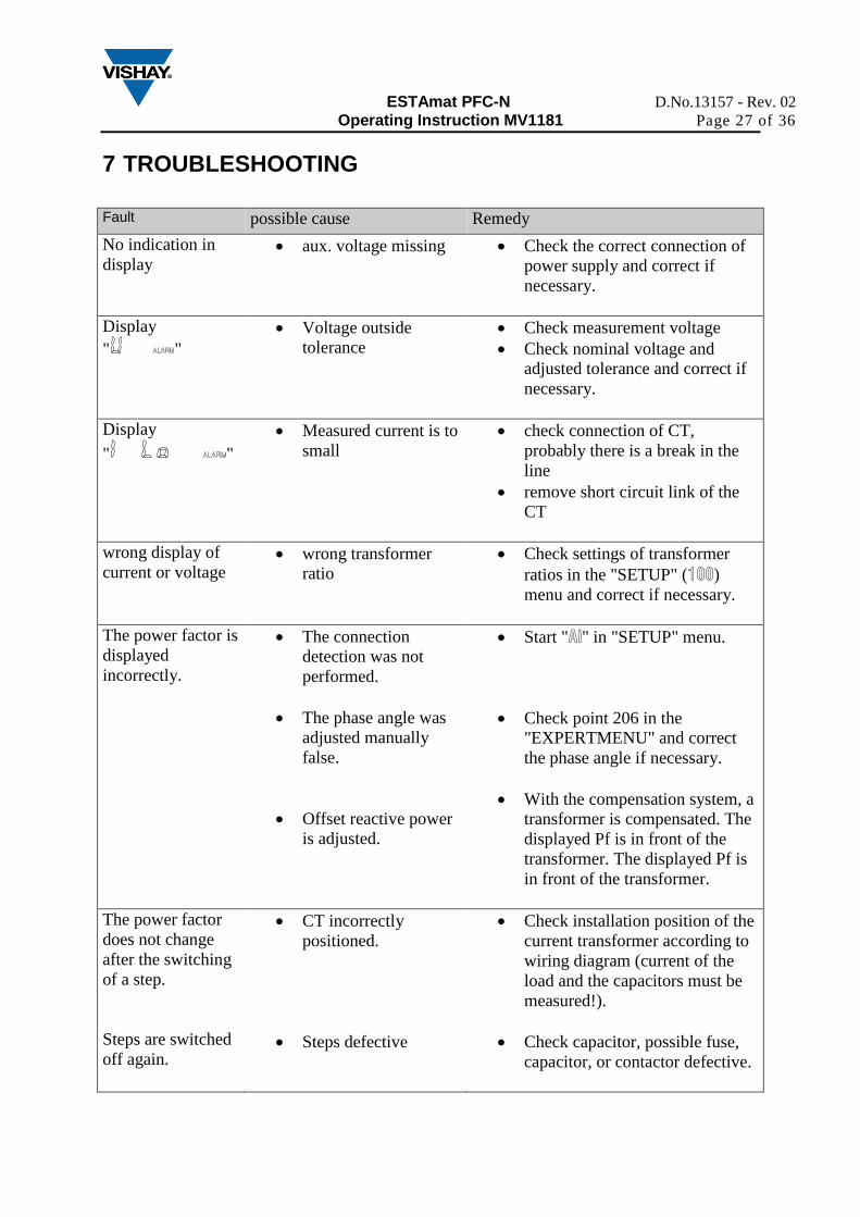
7 TROUBLESHOOTING
Fault possible cause Remedy
No indication in
display aux. voltage missing Check the correct connection of
power supply and correct if
necessary.
Display
" "
Voltage outside
tolerance
Check measurement voltage
Check nominal voltage and
adjusted tolerance and correct if
necessary.
Display
" "
Measured current is to
small
check connection of CT,
probably there is a break in the
line
remove short circuit link of the
CT
wrong display of
current or voltage wrong transformer
ratio
Check settings of transformer
ratios in the "SETUP" (100)
menu and correct if necessary.
The power factor is
displayed
incorrectly.
The connection
detection was not
performed.
The phase angle was
adjusted manually
false.
Offset reactive power
is adjusted.
Start "Ai" in "SETUP" menu.
Check point 206 in the
"EXPERTMENU" and correct
the phase angle if necessary.
With the compensation system, a
transformer is compensated. The
displayed Pf is in front of the
transformer. The displayed Pf is
in front of the transformer.
The power factor
does not change
after the switching
of a step.
Steps are switched
off again.
CT incorrectly
positioned.
Steps defective
Check installation position of the
current transformer according to
wiring diagram (current of the
load and the capacitors must be
measured!).
Check capacitor, possible fuse,
capacitor, or contactor defective.
ESTAmat PFC-N D.No.13157 - Rev. 02
Operating Instruction MV1181 Page 28 of 36
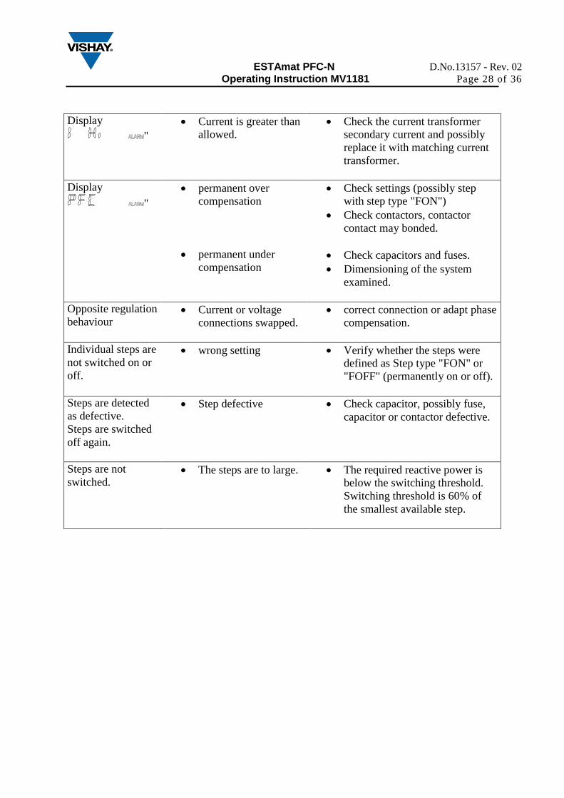
Display
"
Current is greater than
allowed.
Check the current transformer
secondary current and possibly
replace it with matching current
transformer.
Display
"
permanent over
compensation
permanent under
compensation
Check settings (possibly step
with step type "FON")
Check contactors, contactor
contact may bonded.
Check capacitors and fuses.
Dimensioning of the system
examined.
Opposite regulation
behaviour Current or voltage
connections swapped.
correct connection or adapt phase
compensation.
Individual steps are
not switched on or
off.
wrong setting Verify whether the steps were
defined as Step type "FON" or
"FOFF" (permanently on or off).
Steps are detected
as defective.
Steps are switched
off again.
Step defective Check capacitor, possibly fuse,
capacitor or contactor defective.
Steps are not
switched. The steps are to large. The required reactive power is
below the switching threshold.
Switching threshold is 60% of
the smallest available step.

ESTAmat PFC-N D.No.13157 - Rev. 02
Operating Instruction MV1181 Page 29 of 36
8 APPLICATIONS
8.1 Fan Control
The ESTAmat PFC-N is equipped by default with a temperature sensor. The fan is controlled
via one of the switching outputs.
Procedure:
Enable temperature alarm
In the expert menu item 512 set to "YES" (temperature alarm on).
Set temperature thresholds
Set the following items 513 (temperature threshold 1) and 514 (temperature threshold 2the
temperature thresholds. By exceeding the temperature threshold 1 is witched the fan
output. When you exceed the temperature threshold 2, all steps are switched off to prevent
overheating.
Select fan output
Select item 403 in expert menu and adjust for the step which shall work as the fan output
step type "AL".
Features:
In order to prevent hunting of the fan relay, the fan is turned off only at a temperature below
the set limit by at least 3°C. If the ESTAmat PFC-N is equipped with a temperature sensor,
the current cabinet temperature is displayed and the highest measured temperature is stored in
thi. Parallel to the temperature sensor can be connected a thermostat. By close of the
thermostat , the temperature limit 2 is activated.
ESTAmat PFC-N D.No.13157 - Rev. 02
Operating Instruction MV1181 Page 30 of 36
8.2 Switching on target Pf 2 via digital input
By using a switch, the ESTAmat PFC-N will be switched to target Pf 2.
Solution:
Using the temperature input as digital input.
Procedure:
Enable digital input
Set item 510 in expert menu to "YES".
Using digital input as n/o or n/c
In the menu item 511 can be determined whether the digital inputs as n/c (NO) or n/o
(YES) is used.
Features:
The temperature input is used as a digital input, shows the controller at active input "high"
and with not active input "low" instead of the temperature. The controller uses with active
digital input the target Pf 2 and will show "NT" in the display.
ESTAmat PFC-N D.No.13157 - Rev. 02
Operating Instruction MV1181 Page 31 of 36
8.3 Problems with the Step recognition.
The controller is used in a system with rapid changes in load conditions and has problems
with the automatic step recognition
Solution:
To solve this problem, the step sizes must be entered by hand, and the step recognition must
be turned off.
Procedure:
Stop control.
Set item PFC to "OFF" in menu 100 (quick start menu).
switch off Step detection.
Set item 308 to "Yes" (step recognition off) in the expert menu.
enter step sizes.
Setting the nominal value of the capacitors connected at point 402 in the expert menu.
Check step type
For problems with the step detection, it may happen that the connected steps will be stored
by the controller incorrectly as "FIX-OFF". Therefore, the step type of each step should be
controlled under the menu item "403". All steps of the automatic control used, must be use
the step type "AUTO".
Features:
By switching off the automatic step recognition, a step failure or power loss is not reported.
To monitor the system anyway, it is appropriate to enable the control alarm to be alerted in
case of failure timely. (See alarm menu)
ESTAmat PFC-N D.No.13157 - Rev. 02
Operating Instruction MV1181 Page 32 of 36
8.4 Transformer compensation
The compensation of a transformer can be solved with the ESTAmat PFC-N in two ways:
8.4.1 Setting a reactive power offset
Setting reactive power offset. This is added to the required compensation power within the
system.
Procedure:
Determine the required capacitive reactive power to compensate the transformer. Enter the
calculated value in the menu item "312". Control will start immediately with the additional
required reactive power.
Features:
The set here reactive power offset is always added to the measured reactive power. Therefore,
it's always the Pf appears before the transformer. This means that the system can capacitive,
but the measurement of the utility the required Pf recoded.
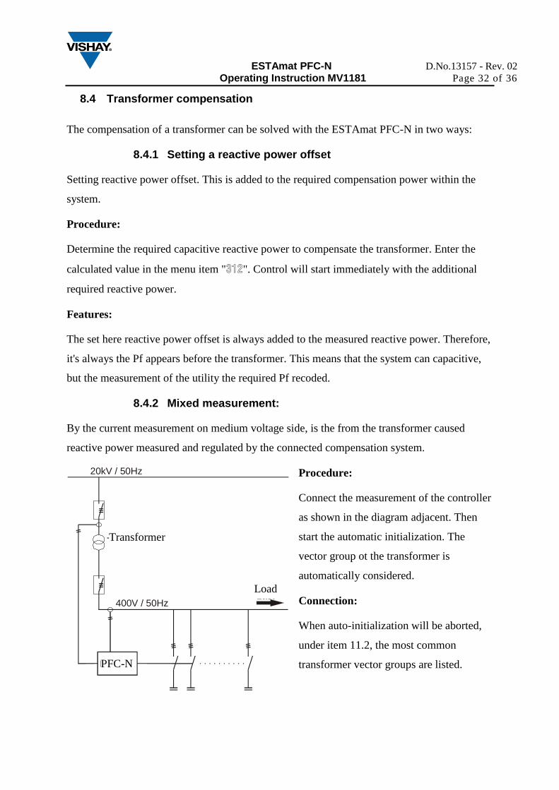
8.4.2 Mixed measurement:
By the current measurement on medium voltage side, is the from the transformer caused
reactive power measured and regulated by the connected compensation system.
Procedure:
Connect the measurement of the controller
as shown in the diagram adjacent. Then
start the automatic initialization. The
vector group ot the transformer is
automatically considered.
Connection:
When auto-initialization will be aborted,
under item 11.2, the most common
transformer vector groups are listed.
20kV / 50Hz
400V / 50Hz
BLR-CX
Last
TransformatorTransformer
Load
PFC-N
ESTAmat PFC-N D.No.13157 - Rev. 02
Operating Instruction MV1181 Page 33 of 36
8.5 Reset defective steps respectively add aditional steps
If the controller has a step recognized as defective (3 switching operations without result), it
will be excluded for 24 hours from the regulation. After this period, the step is tested again
from the controller. If the controller can detect the step it will again be included in the control.
If not the step is blocked again for 24hours after 3 unsuccessful switching cycles. Defect steps
are in the "INFO" menu with the step type "flty" marked and flashing in the step indication.
When a compensation system need additional capacitors to be added, proceed as described
below:
Procedure:
Select item "403" in expert menu and use the buttons to select the corresponding step.
Confirm with ( ) button and use the buttons to adjust step type "AUTO".
Feature:
If a step because of power loss greater than 30% is exchanged, it's appropriate for the step, to
program the nominal step size by hand. Select in menu "402" the affected step and program
the nominal step size.
If the alarm was triggered by a defective contactor should, upon the exchange took place, the
accumulated switching operation under item "404" set to "0".
ESTAmat PFC-N D.No.13157 - Rev. 02
Operating Instruction MV1181 Page 34 of 36
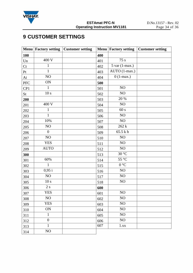
9 CUSTOMER SETTINGS
Menu Factory setting Customer setting Menu Factory setting Customer setting
100 400
Un 400 V 401 75 s
Ct 1 402 5 var (1-max.)
Pt 1 403 AUTO (1-max.)
Ai NO 404 0 (1-max.)
PFC ON 500
CP1 1 501 NO
St 10 s 502 NO
200 503 20 %
201 400 V 504 NO
202 1 505 60 s
203 1 506 NO
204 10% 507 NO
205 NO 508 262 k
206 0 509 65.5 k h
207 NO 510 NO
208 YES 511 NO
209 AUTO 512 NO
300 513 30 °C
301 60% 514 55 °C
302 1 515 0 °C
303 0,95 i 516 NO
304 NO 517 NO
305 10 s 518 NO
306 2 s 600
307 YES 601 NO
308 NO 602 NO
309 YES 603 NO
310 ON 604 NO
311 1 605 NO
312 0 606 NO
313 1 607 1.xx
314 NO
ESTAmat PFC-N D.No.13157 - Rev. 02
Operating Instruction MV1181 Page 35 of 36
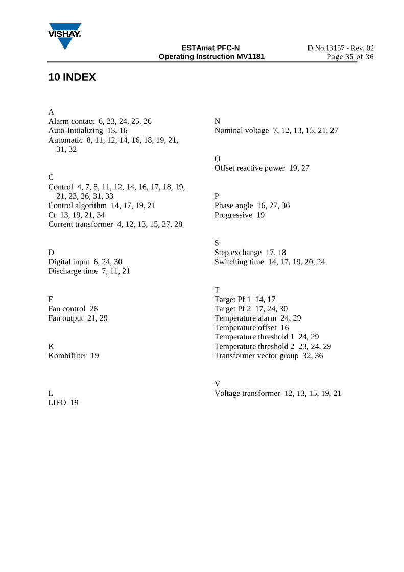
10 INDEX
A
Alarm contact 6, 23, 24, 25, 26
Auto-Initializing 13, 16
Automatic 8, 11, 12, 14, 16, 18, 19, 21,
31, 32
C
Control 4, 7, 8, 11, 12, 14, 16, 17, 18, 19,
21, 23, 26, 31, 33
Control algorithm 14, 17, 19, 21
Ct 13, 19, 21, 34
Current transformer 4, 12, 13, 15, 27, 28
D
Digital input 6, 24, 30
Discharge time 7, 11, 21
F
Fan control 26
Fan output 21, 29
K
Kombifilter 19
L
LIFO 19
N
Nominal voltage 7, 12, 13, 15, 21, 27
O
Offset reactive power 19, 27
P
Phase angle 16, 27, 36
Progressive 19
S
Step exchange 17, 18
Switching time 14, 17, 19, 20, 24
T
Target Pf 1 14, 17
Target Pf 2 17, 24, 30
Temperature alarm 24, 29
Temperature offset 16
Temperature threshold 1 24, 29
Temperature threshold 2 23, 24, 29
Transformer vector group 32, 36
V
Voltage transformer 12, 13, 15, 19, 21
ESTAmat PFC-N D.No.13157 - Rev. 02
Operating Instruction MV1181 Page 36 of 36
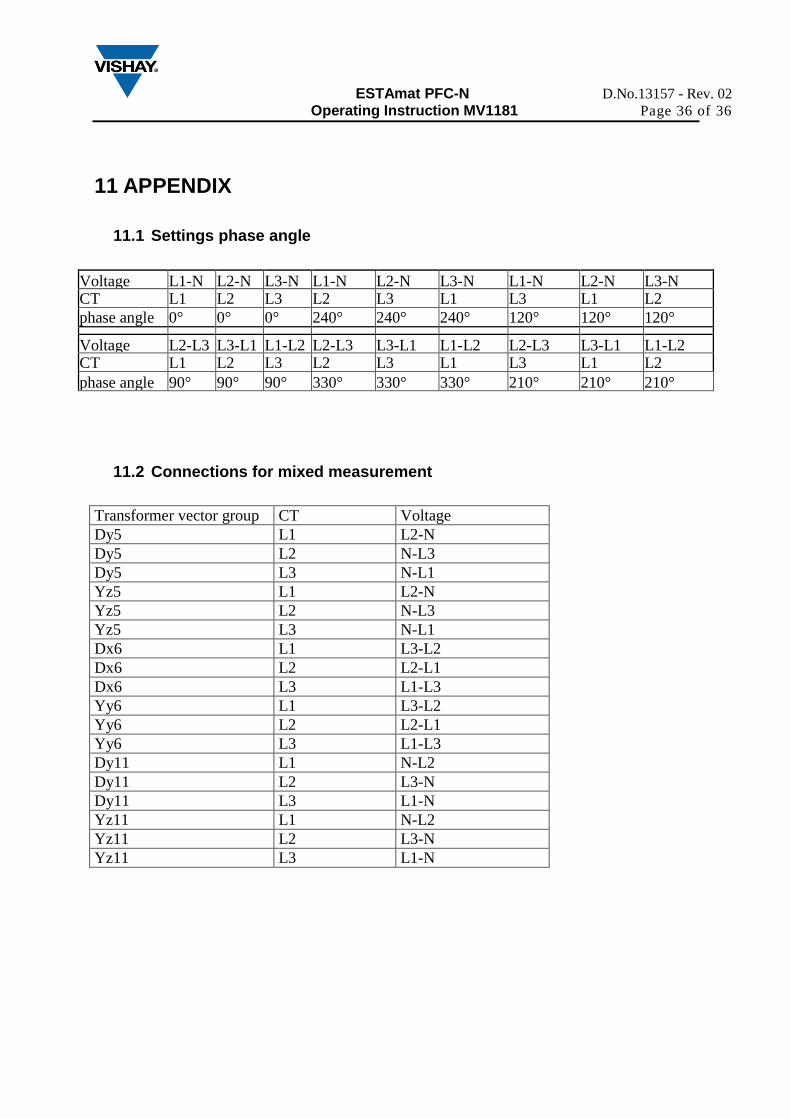
11 APPENDIX
11.1 Settings phase angle
Voltage L1-N L2-N L3-N L1-N L2-N L3-N L1-N L2-N L3-N CT L1 L2 L3 L2 L3 L1 L3 L1 L2
phase angle 0° 0° 0° 240° 240° 240° 120° 120° 120°
Voltage L2-L3 L3-L1 L1-L2 L2-L3 L3-L1 L1-L2 L2-L3 L3-L1 L1-L2 CT L1 L2 L3 L2 L3 L1 L3 L1 L2
phase angle 90° 90° 90° 330° 330° 330° 210° 210° 210°
11.2 Connections for mixed measurement
Transformer vector group CT Voltage
Dy5 L1 L2-N
Dy5 L2 N-L3
Dy5 L3 N-L1
Yz5 L1 L2-N
Yz5 L2 N-L3
Yz5 L3 N-L1
Dx6 L1 L3-L2
Dx6 L2 L2-L1
Dx6 L3 L1-L3
Yy6 L1 L3-L2
Yy6 L2 L2-L1
Yy6 L3 L1-L3
Dy11 L1 N-L2
Dy11 L2 L3-N
Dy11 L3 L1-N
Yz11 L1 N-L2
Yz11 L2 L3-N
Yz11 L3 L1-N