Embed Size (px)
Citation preview
OPERATING INSTRUCTIONS
POWER AMPLIFIERS BA-235BA-260
1. IMPORTANT SAFETY INSTRUCTIONS .... 2
2. SAFETY PRECAUTIONS ........................... 3
3. GENERAL DESCRIPTION ......................... 5
4. FEATURES ................................................. 5
5. NOMENCLATURE AND FUNCTIONSFront ............................................................ 5Rear ............................................................. 6
6. CONNECTIONS 6.1. Removable Terminal Plug
Connection ........................................... 76.2. Input Connections ................................ 76.3. Output Connections .............................. 8
7. REMOTE VOLUME CONTROL
CONNECTION ............................................ 8
8. 2-CHANNEL BROADCAST ........................ 9
9. OPERATION ............................................... 9
10. INSTALLATION PRECAUTIONS ............... 9
11. RACK MOUNTING BRACKET
ATTACHMENT ......................................... 10
12. VOLUME SETTING .................................. 11
13. VOLUME CONTROL COVER .................. 11
14. BLOCK DIAGRAM ................................... 11
15. DIMENSIONAL DIAGRAM ....................... 12
16. SPECIFICATIONS .................................... 12Accessories ............................................... 12Optional products ...................................... 12
MASTER
SIGNAL PEAK POWER
ON
OFF
BASS TREBLE
POWER AMPLIFIER BA-260
0 10
Thank you for purchasing TOA's Power Amplifiers. Please carefully follow the instructions in this manual to ensure long, trouble-free use of your equipment.
TABLE OF CONTENTS
2
1. IMPORTANT SAFETY INSTRUCTIONS
• Read these instructions.
• Keep these instructions.
• Heed all warnings.
• Follow all instructions.
• Do not use this apparatus near water.
• Clean only with dry cloth.
• Do not block any ventilation openings. Install in accordance with the manufacturer's instructions.
• Do not install near any heat sources such as radiators, heat registers, stoves, or other apparatus (includingamplifiers) that produce heat.
• Do not defeat the safety purpose of the polarized or grounding-type plug. A polarized plug has two bladeswith one wider than the other. A grounding type plug has two blades and a third grounding prong. The wideblade or the third prong are provided for your safety. If the provided plug does not fit into your outlet, consultan electrician for replacement of the obsolete outlet.
• Protect the power cord from being walked on or pinched particularly at plugs, convenience receptacles, andthe point where they exit from the apparatus.
• Only use attachments/accessories specified by the manufacturer.
• Use only with the cart, stand, tripod, bracket, or table specified by the manufacturer, or sold with theapparatus. When a cart is used, use caution when moving the cart/apparatus combination to avoid injuryfrom tip-over.
• Unplug this apparatus during lightning storms or when unused for long periods of time.
• Refer all servicing to qualified service personnel. Servicing is required when the apparatus has beendamaged in any way, such as power-supply cord or plug is damaged, liquid has been spilled or objects havefallen into the apparatus, the apparatus has been exposed to rain or moisture, does not operate normally, orhas been dropped.
3
When Installing the Unit
• Do not expose the unit to rain or an environment where it may be splashed by water or other liquids, asdoing so may result in fire or electric shock.
• Use the unit only with the voltage specified on the unit. Using a voltage higher than that which is specifiedmay result in fire or electric shock.
• Do not cut, kink, otherwise damage nor modify the power supply cord. In addition, avoid using the powercord in close proximity to heaters, and never place heavy objects -- including the unit itself -- on the powercord, as doing so may result in fire or electric shock.
• Avoid installing or mounting the unit in unstable locations, such as on a rickety table or a slanted surface.Doing so may result in the unit falling down and causing personal injury and/or property damage.
• External wiring connected to the terminals marked with requires installation by an instructed person.
• The apparatus shall be connected to a mains socket outlet with a protective earthing connection.
• The socket-outlet shall be installed near the equipment and the plug (disconnecting device) shall be easilyaccessible.
• Use the optional Rack mounting bracket MB-25B-BK or MB-25B-J when mounting the unit(s) in anequipment rack. Remove four M4 x 8 screws on both sides of the unit, and mount the bracket there usingthe M4 x 16 screws (supplied with the bracket) instead.
When the Unit is in Use
• Should the following irregularity be found during use, immediately switch off the power, disconnect the powersupply plug from the AC outlet and contact your nearest TOA dealer. Make no further attempt to operate theunit in this condition as this may cause fire or electric shock.
· If you detect smoke or a strange smell coming from the unit· If water or any metallic object gets into the unit · If the unit falls, or the unit case breaks · If the power supply cord is damaged (exposure of the core, disconnection, etc.)· If it is malfunctioning (no tone sounds.)
• To prevent a fire or electric shock, never open nor remove the unit case as there are high voltagecomponents inside the unit. Refer all servicing to your nearest TOA dealer.
• Do not place cups, bowls, or other containers of liquid or metallic objects on top of the unit. If theyaccidentally spill into the unit, this may cause a fire or electric shock.
• Do not insert nor drop metallic objects or flammable materials in the ventilation slots of the unit's cover, asthis may result in fire or electric shock.
2. SAFETY PRECAUTIONS
• Before installation or use, be sure to carefully read all the instructions in this section for correct and safeoperation.
• Be sure to follow all the precautionary instructions in this section, which contain important warnings and/orcautions regarding safety.
• After reading, keep this manual handy for future reference.
Safety Symbol and Message Conventions Safety symbols and messages described below are used in this manual to prevent bodily injury and propertydamage which could result from mishandling. Before operating your product, read this manual first andunderstand the safety symbols and messages so you are thoroughly aware of the potential safety hazards.
Indicates a potentially hazardous situation which, if mishandled, couldresult in death or serious personal injury. WARNING
The exclamation point within an equilateral triangle is intended to alert the user to the presence ofimportant operation and maintenance (servicing) instruction in the literature accompanying theappliance.
4
When Installing the Unit
• Never plug in nor remove the power supply plug with wet hands, as doing so may cause electric shock.
• When unplugging the power supply cord, be sure to grasp the power supply plug; never pull on the corditself. Operating the unit with a damaged power supply cord may cause a fire or electric shock.
• When moving the unit, be sure to remove its power supply cord from the wall outlet. Moving the unit with thepower cord connected to the outlet may cause damage to the power cord, resulting in fire or electric shock.When removing the power cord, be sure to hold its plug to pull.
• Do not block the ventilation slots in the unit's cover. Doing so may cause heat to build up inside the unit andresult in fire.
• Avoid installing the unit in humid or dusty locations, in locations exposed to the direct sunlight, near the heaters,or in locations generating sooty smoke or steam as doing otherwise may result in fire or electric shock.
• To avoid electric shocks, be sure to unplug the unit's power supply cord when connecting speakers.
• Be sure to follow the instructions below when rack-mounting the unit. Failure to do so may cause a fire orpersonal injury.
· Install the equipment rack on a stable, hard floor. Fix it with anchor bolts or take other arrangements toprevent it from falling down.
· When connecting the unit's power cord to an AC outlet, use the AC outlet with current capacity allowable tothe unit.
· No rack-mounting screws are supplied with the unit. Separately prepare the appropriate screws for therack.
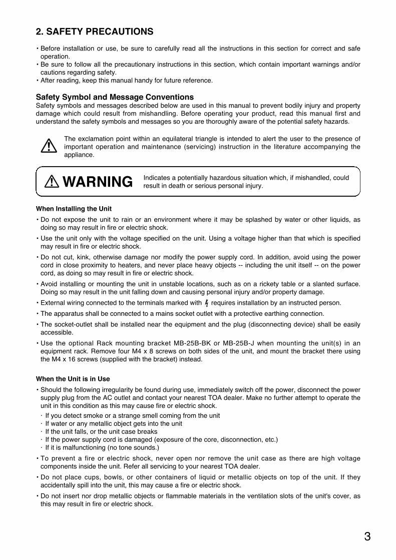
• Keep the amplifier over 10 cm (3.94") away fromobjects that may obstruct air flow to prevent the unit'sinternal temperature rise.
When the Unit is in Use
• Do not place heavy objects on the unit as this may cause it to fall or break which may result in personalinjury and/or property damage. In addition, the object itself may fall off and cause injury and/or damage.
• Make sure that the volume control is set to minimum position before power is switched on. Loud noiseproduced at high volume when power is switched on can impair hearing.
• Do not operate the unit for an extended period of time with the sound distorting. This is an indication of amalfunction, which in turn can cause heat to generate and result in a fire.
• If dust accumulates on the power supply plug or in the wall AC outlet, a fire may result. Clean it periodically.In addition, insert the plug in the wall outlet securely.
• Switch off the power, and unplug the power supply plug from the AC outlet for safety purposes whencleaning or leaving the unit unused for 10 days or more. Doing otherwise may cause a fire or electric shock.
Over 10 cm (3.94") Over 10 cm (3.94")
Over 10 cm(3.94")
Indicates a potentially hazardous situation which, if mishandled, couldresult in moderate or minor personal injury, and/or property damage.CAUTION
L'appareil ne doit pas être exposé aux éclaboussures ou écoulements et tous objets remplis de liquide, telsque vases, ne doivent pas être sur l’appareil.
ATTENTION
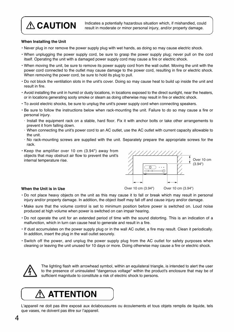
The lighting flash with arrowhead symbol, within an equilateral triangle, is intended to alert the userto the presence of uninsulated "dangerous voltage" within the product's enclosure that may be ofsufficient magnitude to constitute a risk of electric shock to persons.
5
MASTER
SIGNAL PEAK POWER
ON
OFF
BASS TREBLE
POWER AMPLIFIER BA-260
0 10
23 4 5
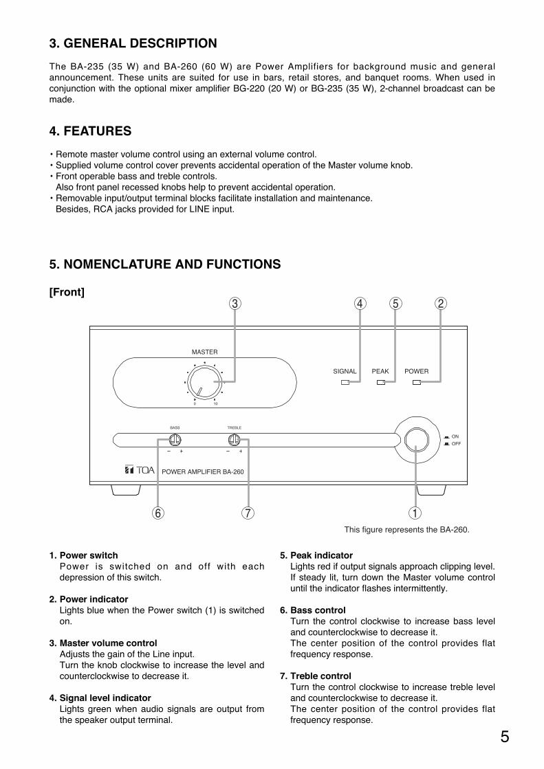
6 7 1This figure represents the BA-260.
5. NOMENCLATURE AND FUNCTIONS
[Front]
1. Power switch Power is switched on and off with eachdepression of this switch.
2. Power indicator Lights blue when the Power switch (1) is switchedon.
3. Master volume control Adjusts the gain of the Line input.Turn the knob clockwise to increase the level andcounterclockwise to decrease it.
4. Signal level indicatorLights green when audio signals are output fromthe speaker output terminal.
5. Peak indicator Lights red if output signals approach clipping level.If steady lit, turn down the Master volume controluntil the indicator flashes intermittently.
6. Bass control Turn the control clockwise to increase bass leveland counterclockwise to decrease it.The center position of the control provides flatfrequency response.
7. Treble controlTurn the control clockwise to increase treble leveland counterclockwise to decrease it.The center position of the control provides flatfrequency response.
3. GENERAL DESCRIPTION
The BA-235 (35 W) and BA-260 (60 W) are Power Amplifiers for background music and generalannouncement. These units are suited for use in bars, retail stores, and banquet rooms. When used inconjunction with the optional mixer amplifier BG-220 (20 W) or BG-235 (35 W), 2-channel broadcast can bemade.
4. FEATURES
• Remote master volume control using an external volume control.• Supplied volume control cover prevents accidental operation of the Master volume knob.• Front operable bass and treble controls.
Also front panel recessed knobs help to prevent accidental operation. • Removable input/output terminal blocks facilitate installation and maintenance.
Besides, RCA jacks provided for LINE input.
6
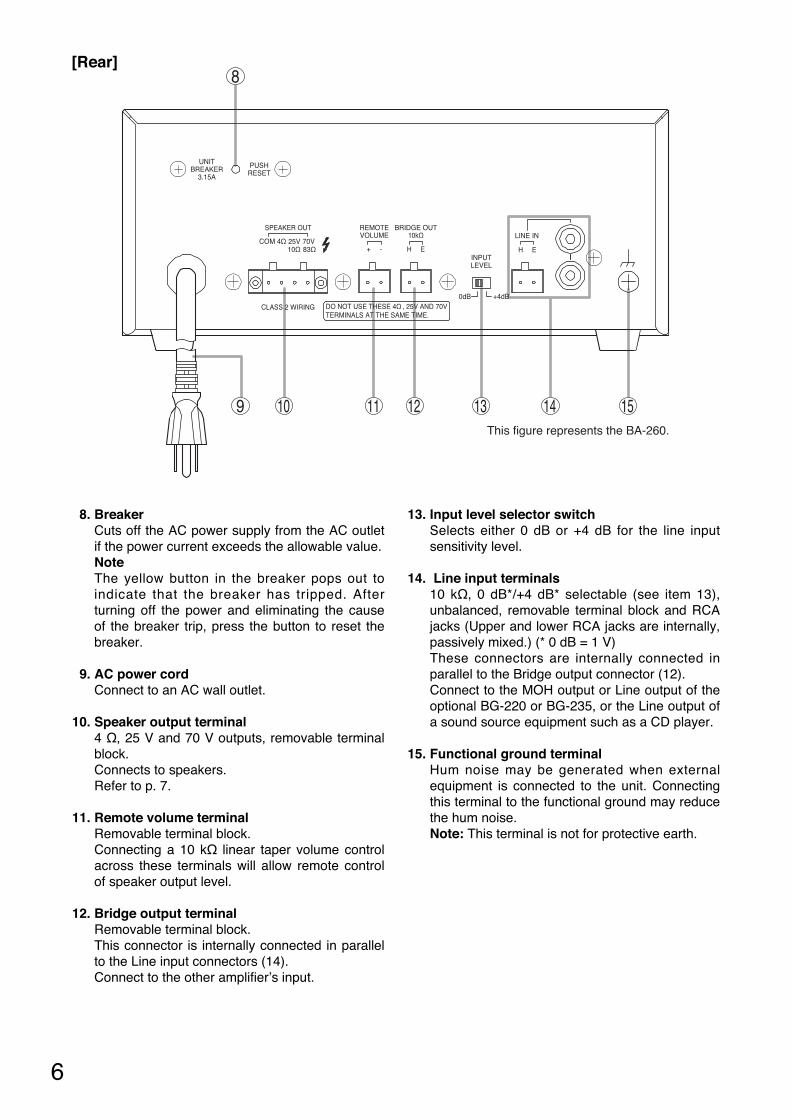
[Rear]
UNITBREAKER
3.15A
PUSHRESET
SPEAKER OUT
4Ω10Ω 83Ω
COM
CLASS 2 WIRING
70V25V
DO NOT USE THESE 4Ω , 25V AND 70VTERMINALS AT THE SAME TIME.
BRIDGE OUT10kΩ
INPUTLEVEL
0dB +4dB
REMOTEVOLUME
H E
LINE IN
H E+ -
10 11 12 13 14 15This figure represents the BA-260.
8
9
8. Breaker Cuts off the AC power supply from the AC outletif the power current exceeds the allowable value.NoteThe yellow button in the breaker pops out toindicate that the breaker has tripped. Afterturning off the power and eliminating the causeof the breaker trip, press the button to reset thebreaker.
9. AC power cordConnect to an AC wall outlet.
10. Speaker output terminal4 Ω, 25 V and 70 V outputs, removable terminalblock.Connects to speakers.Refer to p. 7.
11. Remote volume terminalRemovable terminal block.Connecting a 10 kΩ linear taper volume controlacross these terminals will allow remote controlof speaker output level.
12. Bridge output terminalRemovable terminal block.This connector is internally connected in parallelto the Line input connectors (14).Connect to the other amplifier’s input.
13. Input level selector switchSelects either 0 dB or +4 dB for the line inputsensitivity level.
14. Line input terminals10 kΩ, 0 dB*/+4 dB* selectable (see item 13),unbalanced, removable terminal block and RCAjacks (Upper and lower RCA jacks are internally,passively mixed.) (* 0 dB = 1 V)These connectors are internally connected inparallel to the Bridge output connector (12).Connect to the MOH output or Line output of theoptional BG-220 or BG-235, or the Line output ofa sound source equipment such as a CD player.
15. Functional ground terminalHum noise may be generated when externalequipment is connected to the unit. Connectingthis terminal to the functional ground may reducethe hum noise.Note: This terminal is not for protective earth.
7
6. CONNECTIONS
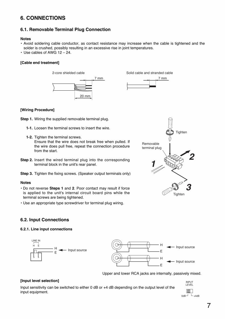
6.1. Removable Terminal Plug Connection
Notes• Avoid soldering cable conductor, as contact resistance may increase when the cable is tightened and the
solder is crushed, possibly resulting in an excessive rise in joint temperatures.• Use cables of AWG 12 – 24.
[Cable end treatment]
7 mm 7 mm
20 mm
2-core shielded cable Solid cable and stranded cable
[Wiring Procedure]
Step 1. Wiring the supplied removable terminal plug.
1-1. Loosen the terminal screws to insert the wire.
1-2. Tighten the terminal screws.Ensure that the wire does not break free when pulled. Ifthe wire does pull free, repeat the connection procedurefrom the start.
Step 2. Insert the wired terminal plug into the correspondingterminal block in the unit's rear panel.
Step 3. Tighten the fixing screws. (Speaker output terminals only)
Notes• Do not reverse Steps 1 and 2. Poor contact may result if force
is applied to the unit's internal circuit board pins while theterminal screws are being tightened.
• Use an appropriate type screwdriver for terminal plug wiring.
Removable terminal plug
12
3
Tighten
Tighten
6.2. Input Connections
6.2.1. Line input connections
LINE IN
H E
EH Input source
Input source
Input source
H
E
H
E
Upper and lower RCA jacks are internally, passively mixed.
[Input level selection]
Input sensitivity can be switched to either 0 dB or +4 dB depending on the output level of theinput equipment.
INPUTLEVEL
0dB +4dB
8
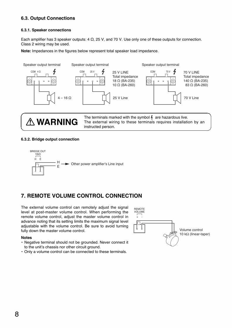
7. REMOTE VOLUME CONTROL CONNECTION
The external volume control can remotely adjust the signallevel at post-master volume control. When performing theremote volume control, adjust the master volume control inadvance noting that its setting limits the maximum signal leveladjustable with the volume control. Be sure to avoid turningfully down the master volume control.
Notes• Negative terminal should not be grounded. Never connect it
to the unit’s chassis nor other circuit ground.• Only a volume control can be connected to these terminals.
Volume control10 kΩ (linear-taper)
REMOTEVOLUME
+ -
6.3.2. Bridge output connection
BRIDGE OUT10kΩ
H E
EH Other power amplifier’s Line input
6.3. Output Connections
6.3.1. Speaker connections
Each amplifier has 3 speaker outputs: 4 Ω, 25 V, and 70 V. Use only one of these outputs for connection.Class 2 wiring may be used.
Note: Impedances in the figures below represent total speaker load impedance.
70 V LINETotal impedance140 Ω (BA-235) 83 Ω (BA-260)
25 V LINETotal impedance18 Ω (BA-235)10 Ω (BA-260)
Speaker output terminal
COM 4 Ω
Speaker output terminal
COM 25 V
Speaker output terminal
COM 70 V
4 – 16 Ω 70 V Line25 V Line
The terminals marked with the symbol are hazardous live.The external wiring to these terminals requires installation by aninstructed person.
WARNING
9
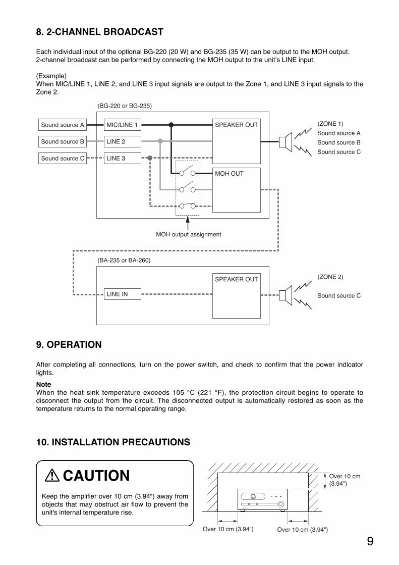
8. 2-CHANNEL BROADCAST
Each individual input of the optional BG-220 (20 W) and BG-235 (35 W) can be output to the MOH output. 2-channel broadcast can be performed by connecting the MOH output to the unit’s LINE input.
(Example)When MIC/LINE 1, LINE 2, and LINE 3 input signals are output to the Zone 1, and LINE 3 input signals to theZone 2.
Sound source A
Sound source B
Sound source C
MIC/LINE 1 SPEAKER OUT
MOH OUT
LINE 2
LINE 3
(BG-220 or BG-235)
MOH output assignment
(ZONE 1)
Sound source A
Sound source B
Sound source C
LINE IN
SPEAKER OUT
(BA-235 or BA-260)
(ZONE 2)
Sound source C
9. OPERATION
After completing all connections, turn on the power switch, and check to confirm that the power indicatorlights.
NoteWhen the heat sink temperature exceeds 105 °C (221 °F), the protection circuit begins to operate todisconnect the output from the circuit. The disconnected output is automatically restored as soon as thetemperature returns to the normal operating range.
10. INSTALLATION PRECAUTIONS
Keep the amplifier over 10 cm (3.94") away fromobjects that may obstruct air flow to prevent theunit's internal temperature rise.
CAUTION
Over 10 cm (3.94") Over 10 cm (3.94")
Over 10 cm(3.94")
10
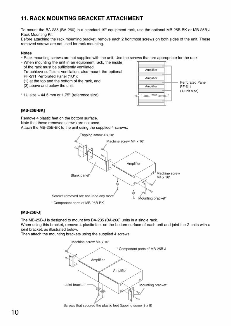
[MB-25B-J]
The MB-25B-J is designed to mount two BA-235 (BA-260) units in a single rack.When using this bracket, remove 4 plastic feet on the bottom surface of each unit and joint the 2 units with ajoint bracket, as illustrated below.Then attach the mounting brackets using the supplied 4 screws.
Mounting bracket*Joint bracket*
Machine screw M4 x 10*
Amplifier
Amplifier
* Component parts of MB-25B-J
Screws that secured the plastic feet (tapping screw 3 x 8)
11. RACK MOUNTING BRACKET ATTACHMENT
To mount the BA-235 (BA-260) in a standard 19" equipment rack, use the optional MB-25B-BK or MB-25B-JRack Mounting Kit.Before attaching the rack mounting bracket, remove each 2 frontmost screws on both sides of the unit. Theseremoved screws are not used for rack mounting.
Notes• Rack mounting screws are not supplied with the unit. Use the screws that are appropriate for the rack.• When mounting the unit in an equipment rack, the inside
of the rack must be sufficiently ventilated.To achieve sufficient ventilation, also mount the optionalPF-511 Perforated Panel (1U*):(1) at the top and the bottom of the rack, and(2) above and below the unit.
* 1U size = 44.5 mm or 1.75" (reference size)
[MB-25B-BK]
Remove 4 plastic feet on the bottom surface.Note that these removed screws are not used.Attach the MB-25B-BK to the unit using the supplied 4 screws.
Amplifier
Amplifier
AmplifierPerforated PanelPF-511 (1-unit size)
Mounting bracket*
Blank panel*
Tapping screw 4 x 10*
Machine screw M4 x 16*
Machine screwM4 x 16*
Amplifier
* Component parts of MB-25B-BK
Screws removed are not used any more.
11
Volume control knob
YA-920 Volume control cover (accessory)
1
23
12. VOLUME SETTING
Output levels are adjustable with the Master volume control. For music play or announcement, adjust thevolume control so that the signal indicator lights intermittently. Note that the sound quality is downgradedwhen the peak indicator remains lit.
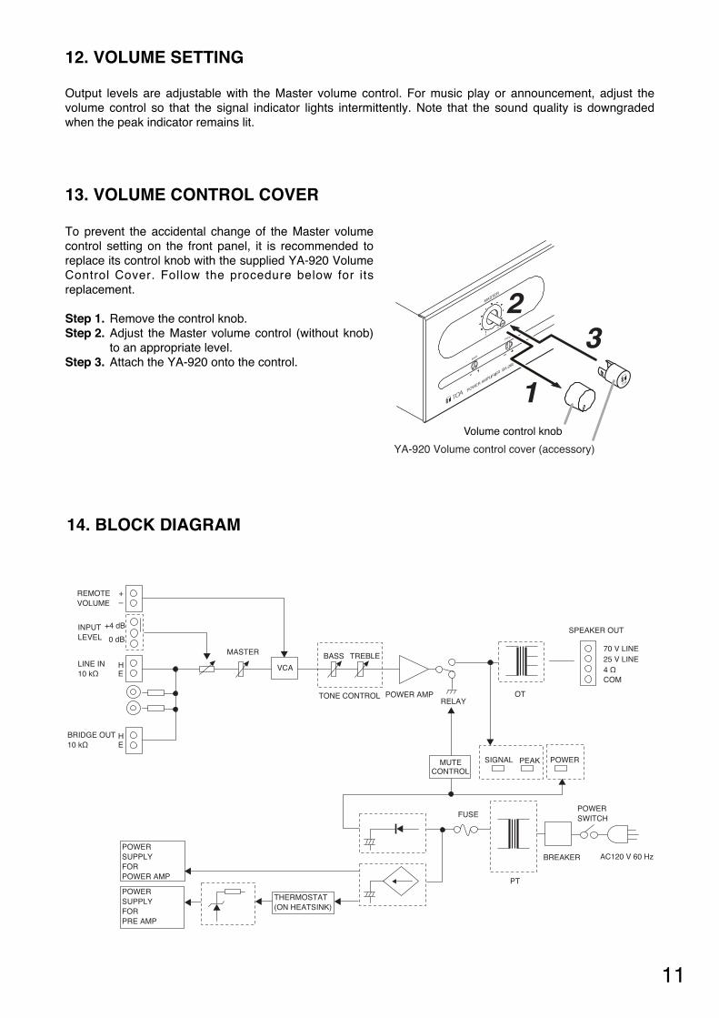
13. VOLUME CONTROL COVER
To prevent the accidental change of the Master volumecontrol setting on the front panel, it is recommended toreplace its control knob with the supplied YA-920 VolumeControl Cover. Follow the procedure below for itsreplacement.
Step 1. Remove the control knob.Step 2. Adjust the Master volume control (without knob)
to an appropriate level.Step 3. Attach the YA-920 onto the control.
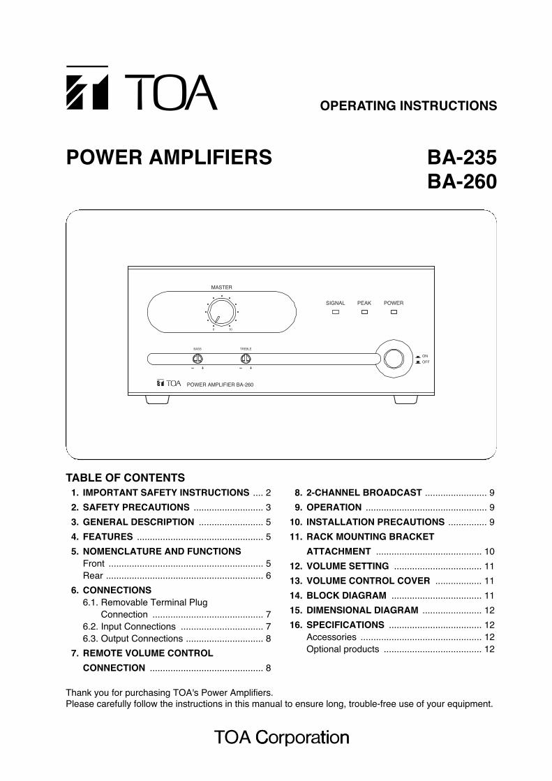
14. BLOCK DIAGRAM
POWER AMP
SPEAKER OUT
AC120 V 60 HzPOWERSUPPLYFORPOWER AMP
70 V LINE
LINE IN10 kΩ
HE
MASTER25 V LINE4 ΩCOM
OTTONE CONTROL
BASS TREBLE
PTPOWERSUPPLYFORPRE AMP
RELAY
BREAKER
SIGNAL PEAK POWER
BRIDGE OUT10 kΩ
HE
POWERSWITCHFUSE
VCA
REMOTEVOLUME
+–
INPUTLEVEL
+4 dB
0 dB
THERMOSTAT(ON HEATSINK)
MUTECONTROL
C33-35-203-80
URL: http://www.toa.jp/
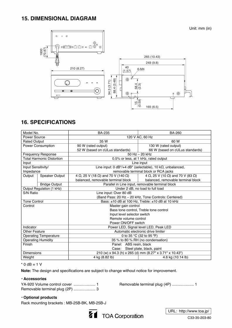
16. SPECIFICATIONS
* 0 dB = 1 V
Note: The design and specifications are subject to change without notice for improvement.
• Accessories
Model No. BA-235 BA-260Power Source 120 V AC, 60 HzRated Output 35 W 60 WPower Consumption 90 W (rated output) 130 W (rated output)
52 W (based on cULus standards) 66 W (based on cULus standards)Frequency Response 50 Hz – 20 kHzTotal Harmonic Distortion 0.5% or less, at 1 kHz, rated outputInput Line inputInput Sensitivity/ Line input: 0 dB*/+4 dB* (selectable), 10 kΩ, unbalanced, Impedance removable terminal block or RCA jacksOutput Speaker Output 4 Ω, 25 V (18 Ω) and 70 V (140 Ω) 4 Ω, 25 V (10 Ω) and 70 V (83 Ω)
balanced, removable terminal block balanced, removable terminal blockBridge Output Parallel in Line input, removable terminal block
Output Regulation (1 kHz) Under 2 dB, no load to full loadS/N Ratio Line input: Over 80 dB
(Band Pass: 20 Hz – 20 kHz, Tone Controls: Centered)Tone Control Bass: ±10 dB at 100 Hz, Treble: ±10 dB at 10 kHzControl Master gain control
Bass tone control, Treble tone controlInput level selector switchRemote volume controlPower ON/OFF switch
Indicator Power LED, Signal level LED, Peak LEDOther Feature Automatic electronic drive limiterOperating Temperature 0 to 35 °C (32 to 95 ºF)Operating Humidity 35 % to 80 % RH (no condensation)Finish Panel: ABS resin, black
Case: Steel plate, black, paintDimensions 210 (w) x 94.3 (h) x 265 (d) mm (8.27" x 3.71" x 10.43")Weight 4 kg (8.82 lb) 4.6 kg (10.14 lb)
YA-920 Volume control cover .................... 1Removable terminal plug (2P) .................... 3
Removable terminal plug (4P) .................... 1
• Optional productsRack mounting brackets : MB-25B-BK, MB-25B-J
15. DIMENSIONAL DIAGRAM
Unit: mm (in)
1800
(70.
87)
210 (8.27) 6-M4
265 (10.43)
249 (9.8)
40(1.57)
165 (6.5)
15(0
.59)
58.4
(2.3
)
94.3
(3.
71)
88.4
(3.
48)