Embed Size (px)
Citation preview


Index
Operating manual (Serial number) Page 3 of 27
Lift 240
Content
1 General information.................................................................5 1.1 Delivery scope and responsibilities ..........................................5
2 Safety ........................................................................................6 2.1 Intended Use............................................................................6 2.2 Safety signs..............................................................................6 2.2.1 Structure of safety information .................................................6 2.2.2 Safety signs and their importance............................................7 2.2.3 Icons used in the document .....................................................7 2.3 Safety instructions....................................................................8 2.4 Safety concept .......................................................................10 2.4.1 General information................................................................10 2.5 Residual risks.........................................................................10 2.6 Staff requirements, due diligence...........................................10 2.6.1 General information................................................................10 2.6.2 Due diligence .........................................................................11 2.6.3 Training ..................................................................................11 2.7 In an emergency ....................................................................11
3 Specifications.........................................................................12
4 Machine description ..............................................................13 4.1 Function description ...............................................................14
5 Transport ................................................................................15
6 Installation and startup .........................................................16 6.1 Assembly................................................................................16 6.1.1 Safety instructions for the installation.....................................16 6.1.2 Procedure...............................................................................16 6.2 Startup....................................................................................17 6.3 Coordination for the radio frequency......................................17 6.4 Setting the end stop ...............................................................18
7 Operation ................................................................................19 7.1 Safety instructions for the operation.......................................19 7.2 Switching on and off...............................................................20
8 Fault diagnosis.......................................................................21
9 Maintenance ...........................................................................22 9.1 Safety instructions for maintenance and repair......................22 9.2 Battery replacement ...............................................................23

Index
Operating manual (Serial number) Page 4 of 27
Lift 240
10 Dismantling and disposal .....................................................24 10.1 Removal .................................................................................24 10.2 Storage...................................................................................24 10.3 Disposal .................................................................................24
11 Annex ......................................................................................26 11.1 Applicable documents ............................................................26
12 Warranty deed ........................................................................27
Figures
Figure. 1 Delivery scope...................................................................5 Figure. 2 View ................................................................................13 Figure. 3 Setting the end stop ........................................................18

General information
Operating manual (Serial number) Page 5 of 27
Lift 240
1 General information
1.1 Delivery scope and responsibilities The electric hoist "Lift 240" was developed and built by Bochem Instrumente GmbH.
Technical changes based on new research and technologies are made without prior notice.
Subsequent changes by the operator are not the responsibility of the manufacturer.
Warranty The warranty is governed by the laws of the Federal Republic of Germany.
The delivery scope includes:
Figure. 1 Delivery scope
• Electric hoist "Lift 240"
• Wireless remote control
• Power supply
• Operating manual
• Replacement battery

Safety
Operating manual (Serial number) Page 6 of 27
Lift 240
2 Safety
2.1 Intended Use The wireless-controlled electric scissor lift table Lift 240 is used to lift laboratory equipment and devices.
The application range of the lift table is the area of industry and research within buildings.
The lifting table is movable, i.e. not intended for a permanent installation.
It is intended for the connection to a public power supply network.
Improper use is the lifting of objects that exceed the maximum allowable weight.
The device must not be used in hazardous areas!
2.2 Safety signs
2.2.1 Structure of safety information The following signal words are used in this document in conjunction with safety signs to illustrate possible dangers.
Danger! Death or serious bodily injuries will occur, if the respective precautionary measures are not taken.
Warning! Death or serious bodily injuries can occur, if the respective precautionary measures are not taken.
Caution! Minor bodily injuries can occur, if the appropriate precautionary measures are not taken.
Attention! Property damages can occur, if the appropriate precautionary measures are not taken.
Information Here you receive information and instructions to perform the following tasks effectively and safely.

Safety
Operating manual (Serial number) Page 7 of 27
Lift 240
2.2.2 Safety signs and their importance The importance of safety signs is indicated by shapes and colors.
Shape Color Importance
Safety color red Contrast color white
Prohibition
Safety color yellow Contrast color black
Warning
Safety color blue Contrast color white
Order
2.2.3 Icons used in the document
Icon Importance Icon Importance
Warning of a hazardous area or situation
Warning against a tripping risk
Warning against dangerous electrical voltage
Warning against hand injuries
Disconnect prior to performing work
Do not touch, live parts
Information for disposing of substances

Safety
Operating manual (Serial number) Page 8 of 27
Lift 240
2.3 Safety instructions Prerequisite for the safe use and trouble-free operation of the lift table is the knowledge of the basic safety instructions and occupational safety regulations.
This operating manual contains all the necessary information to operate the machine safely.
The internal health and safety regulations must be observed.
Warning! Ignoring the operating instructions can cause personal injuries and equipment failures. > The operating manual, especially the safety instructions must be
read and applied by every person who works with the lift table. > Only change parameters and settings after carefully reading the
operating manual.
Danger! Danger to life by touching live parts. • Work on the electrical equipment must only be carried out by
authorized trained personnel. • Faulty connections or settings can result in damages. • The device may only be operated with the supplied cables and
wires. • Do not perform work on energized parts. • Replace damaged cables immediately. Attach loose connections.
Carry out work only after disconnecting the power supply (pulling the plug).
• Cables may not be pinched or crimped. Cables must be routed so that they will not form tripping hazards or can be damaged. Do not place anything on the cables and connections.
Risk of explosions • The lift table cannot be used in areas at risk of explosions!
Warning! Risk of injuries by smashing laboratory equipment and released chemicals, material and functional damage! • Observe the correct adjustment of the height limit • Keep the lift table in view during the process

Safety
Operating manual (Serial number) Page 9 of 27
Lift 240
Warning! Risk of crushing the hands between the lift table scissors! • Do not operate the lift table without bellows • replace defective bellows
(contact the manufacturer)
Warning! Risk of tripping! > Make sure that no loose cables or objects are located on the floor
in the work area. > Place the device and the connections so that no one steps on it,
or drives or stumbles over it.
Attention! Material and functional damage! • The device may not be doused with liquids, sprayed with water or
be exposed to rain! • Verify the stability when transporting and at the initial startup.

Safety
Operating manual (Serial number) Page 10 of 27
Lift 240
2.4 Safety concept
2.4.1 General information Protection is the objective:
• of the operator against injuries,
• the lift table against damages and standstills,
• the environment against dangers.
The following protective measures were applied in reference to a risk analysis:
• 12 V power supply for the drive unit to protect against electrical shock.
• Bellows over scissor rods and drive unit
• mechanical height limitation
• Battery-powered wireless remote control
• Flare signals as a status indicator,
• Safety instructions on the device and in the operating instructions.
2.5 Residual risks The rated loads of max. 25 kg may not be exceeded.
Note Observe all • warnings and safety instructions, • other markings, such as transportation devices attached o the
device.
2.6 Staff requirements, due diligence
2.6.1 General information Never allow personnel under the influence of response-reducing substances or is incapable of operating the machine based on health reason to operate the device.
Note The operating instructions must always be available at the location of the device. The location must be known to employees.

Safety
Operating manual (Serial number) Page 11 of 27
Lift 240
2.6.2 Due diligence Personnel must:
• have read and understood the operating instructions
• be trained in the operation of the equipment
• know how to perform individual jobs
• be medically able to use the device
2.6.3 Training Work on the machine may be performed by reliable and trained personnel.
Maintenance work may be performed by professionals who due to their specialized training, knowledge, experience and knowledge of the relevant provisions assess the work assigned to them, identify potential hazards and can take necessary measures to reduce accident hazards.
2.7 In an emergency
Note the following points:
• Locations of first aid stations must be known.
• Personnel must be informed of their response in an emergency.
• The proper response should be checked regularly and recorded accordingly.

Specifications
Operating manual (Serial number) Page 12 of 27
Lift 240
3 Specifications
Measurements Dimensions (retracted)
L x W x H 240 x 240 x 120 mm
Footprint: 260 x 260 mm Max. height 300 mm Work area (space requirement) 240 x 240 mm Weight 6 kg
Performance data Traversing speed 480 mm/min Min to max 320 mm/min Traversing distance of scissors max.
180 mm
Load capacity max. 25 kg
Motor data Rated torque 5 Nm Idle speed 70 rpm Tightening torque 56 Nm Transmission ratio 69:1 Protection type IP 24
Energy supply Power consumption 12,000 mA Supply voltage of transformer 100 - 240 VAC, 50/60 Hz Power output 24 V Battery remote control 3 V, lithium cell CR2430
Environmental conditions Approved ambient temperature 5 °C to 45 °C Noise emissions < 40 dB (A)
Material Work area 18/10 steel Housing 18/10 steel Bellows PTFE

Machine description
Operating manual (Serial number) Page 13 of 27
Lift 240
4 Machine description
Figure. 2 View
Item Designation 1 Lift platform 2 Bellows (covers electric motor and lift mechanics) 3 Base 4 ON / OFF switch 5 LED ready, UP / DOWN 6 Knurled nut, adjustable end stop 7 AC adapter connector on the back 8 Power supply 9 Remote control
4
1
5
2
3
6
8
9
7

Machine description
Operating manual (Serial number) Page 14 of 27
Lift 240
4.1 Function description The lift table Lift 240 is used for leveling laboratory equipment (e.g. glasses, flasks, Bunsen burners, etc.) when conducting scientific procedures such as in a chemistry lab.
The scissor lift of the table device is powered by a 24V electric motor with worm gear.
A laboratory unit placed on the lifting platform can be continuously lifted by remote control or lowered.
The maximum lifting height may be limited by an adjusting wheel fixation (see Section 0).
The remote control allows the of operating multiple lift tables via a display selection. Each lift table must first be taught to its control frequency (see Section 0).
The remote control has a power saving mode and is activated by pressing the red button.
Transport
Operating manual (Serial number) Page 15 of 27
Lift 240
5 Transport
The lift table is secured in its packaging against damages during transport.
Do not lift the lift table during transport by the lifting platform or bellows. The bellows could be damaged. Hold the lift table by the base during transport.
Attention! Material damage and risk of injuries! • Work carefully - hands and feet can be crushed • When transporting the lift table, secure it against falling and
crashing. • Secure loose equipment parts before transporting against falling.

Installation and startup
Operating manual (Serial number) Page 16 of 27
Lift 240
6 Installation and startup
6.1 Assembly
6.1.1 Safety instructions for the installation
Attention! Damage to the machine! • Maintain a safe location for the device. • Select a dry, level and slip-proof location. • Watch for good ergonomics • Make sure that no cables are pinched.
Warning! Risk of tripping! • Make sure that no loose cables or objects are located on the floor
in the work area. • Place the device and the connections so that no one steps on it,
or drives or stumbles over it.
6.1.2 Procedure
• Select a suitable location
Power supply:
• Connect the power supply with the lift table (1) - Connection pos (2).
• Plug the power cable (3) into the power supply. Plug the power cable into a grounded socket.
1
2
3

Installation and startup
Operating manual (Serial number) Page 17 of 27
Lift 240
6.2 Startup
Switch the device on with the red toggle switch. The blue and red LED flash very quickly.
Now press the bottom or top button of the remote control for about 3 seconds until the blue LED on the top or the red LED on the bottom flashes more slowly. Now you can traverse the lift platform by pressing the remote control with the top button for up (UP) and with the lower knob for down (DOWN).
6.3 Coordination for the radio frequency Are each lift table must be adjusted for the signal detection of the radio frequency of the remote control.
• For teaching, the upper or the lower button of the remote control must be pressed sequentially for 3 seconds when the lift table is switched on.
The blue (1) or red (2) LED at the base of the lift table flashes during the teach-in in quick succession. If the motor controller has detected the appropriate signal, the blue and red LED flash more slowly. The unit is operational.
• Lift and lower the lift table for a trial without a load.
The lift table moves until the upper or lower button of the remote control is pressed or until the maximum or minimum position is reached. A brief, inadvertent contact with the control buttons has no effect.
Note When operating several lift tables, it is recommended to number the individual lift tables, for example, with labels to prevent any mix-ups and therefore accidents.
1
2

Installation and startup
Operating manual (Serial number) Page 18 of 27
Lift 240
6.4 Setting the end stop
Figure. 3 Setting the end stop
In order to adjust the end stop of the lift platform, the lateral surface knurled nut (1) must be loosened. The slide can now be adjusted in direction "- " or "+".
The slide is now locked in place by tightening the knurled nut.
When adjusting the slide to the stop in direction "+", the maximum height of the lift platform is reached. Shifting in direction "-" limits the height.
You need a measuring tape or yardstick to determine the upper endpoint.
Raise the loaded lift platform by pressing the blue button on the remote control until the desired height is reached.
Is the desired height is reached, shift the slide until it audibly snaps into place. Now tighten the thumbscrew. The end stop is now adjusted.
Based on the design, the lift platform can be lowered somewhat further when reaching of minimum height by pushing the lift platform manually down.
1
Operation
Operating manual (Serial number) Page 19 of 27
Lift 240
7 Operation
7.1 Safety instructions for the operation
Warning! Ignoring the operating instructions can cause personal injuries and equipment failures. > The operating manual, especially the safety instructions must be
read and applied by every person who works with Lift 240. > Only change parameters and settings after carefully reading the
operating manual.
Risk of explosions • The lift table cannot be used in areas at risk of explosions!
Warning! Risk of injuries by smashing laboratory equipment and released chemicals, material and functional damage! • Observe the correct adjustment of the height limit • Keep the lift table in view during the process
Warning! Risk of crushing and shearing the hands between the lift table scissors! • Do not operate the lift table without bellows • replace defective bellows
(contact the manufacturer)
Caution! Material and functional damage, bearing damage! • Please note the maximum load capacity. • Carefully load the lift platform. Set the rated load centered on the
floor area of the lifting platform.
Operation
Operating manual (Serial number) Page 20 of 27
Lift 240
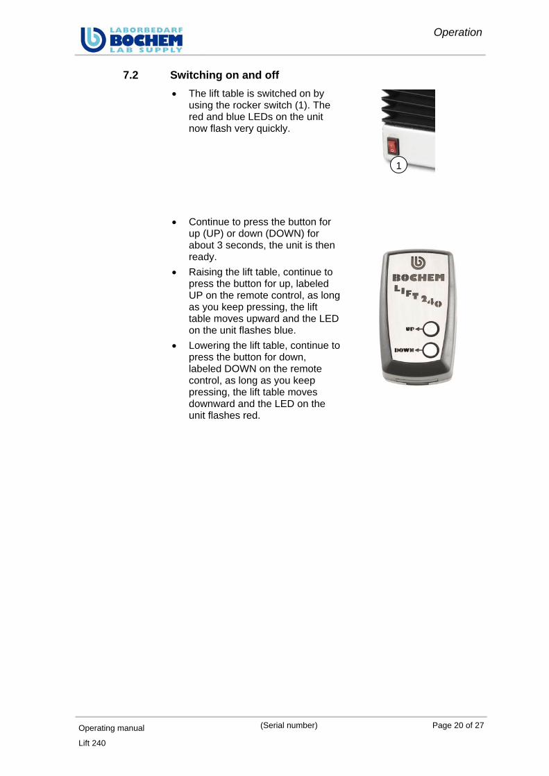
7.2 Switching on and off • The lift table is switched on by
using the rocker switch (1). The red and blue LEDs on the unit now flash very quickly.
• Continue to press the button for up (UP) or down (DOWN) for about 3 seconds, the unit is then ready.
• Raising the lift table, continue to press the button for up, labeled UP on the remote control, as long as you keep pressing, the lift table moves upward and the LED on the unit flashes blue.
• Lowering the lift table, continue to press the button for down, labeled DOWN on the remote control, as long as you keep pressing, the lift table moves downward and the LED on the unit flashes red.
1

Fault diagnosis
Operating manual (Serial number) Page 21 of 27
Lift 240
8 Fault diagnosis
By using the following table for the fault diagnostics, any faults occurring on the unit can be located and remedied.
Problem Possible cause Solution
Power supply, power plug not connected
Connect the power plug
Remote control not functioning Replace the battery of the remote control
Radio signal is not detected Teach in the receiver of the control unit
Defective motor Please contact our service department
Lift table switched on, no function

Maintenance
Operating manual (Serial number) Page 22 of 27
Lift 240
9 Maintenance
9.1 Safety instructions for maintenance and repair
Danger! Danger to life by touching live parts. • Work on the electrical equipment must only be carried out by
authorized trained personnel. • Do not perform work on energized parts. • Replace damaged cables immediately. Attach loose connections.
Work only when the main switch is switched off and locked. • Cables may not be pinched or crimped. Cables must be routed
so that they will not form tripping hazards or can be damaged.
Warning! Risk of crushing the hands between the lift table scissors! • Do not operate the lift table without bellows • replace defective bellows
(contact the manufacturer) Please contact our technical service personnel when:
• the power cable is frayed or the plug / the power supply unit is damaged;
• the bellows are damaged;
• the lift motor is defective;
• fluid was spilled over the device;
• the unit was exposed to rain, water or other liquids;
• the unit was dropped or damaged;
• the performance of the device changed significantly.

Maintenance
Operating manual (Serial number) Page 23 of 27
Lift 240
9.2 Battery replacement If the LED's on the base of the lift table are not flashing when activating a remote control button, it is possible that the battery of the remote control is empty.
Even after longer storage periods, the 3 V lithium-knob cell (CR2430) may have to be replaced.
The battery must be replaced at least after 6 months.
Fig. 1 Fig. 2
Push cover forward to open Remove the cover
Fig. 3 Fig. 4 Push the battery out Insert a new battery
Fig. 1 – Push the cover on the back of the remote control forward at a light pressure
Fig. 2 – Remove the cover
Fig. 3 – Push the battery out with a pointed object
Fig. 4 – Insert a new 3-volt lithium coin cell by hand and put the lid back on

Dismantling and disposal
Operating manual (Serial number) Page 24 of 27
Lift 240
10 Dismantling and disposal
10.1 Removal > Disconnect the unit from the electrical energy supply and other
supply connections.
10.2 Storage > Store the device and components dry and protected from the
elements.
If the storage conditions are not met, components may corrode or age prematurely. The service life of the device is reduced.
10.3 Disposal
Information! Protect the environment! Handling and disposal of old parts are subject to legal regulations.
Operating manual (Serial number) Page 25 of 27
Lift 240
EC Conformity Declaration Within the scope of the EC Directive for Machinery 2006/42/EG Annex II, 1 A and: EG 2004/108/EG – EMC Directive Manufacturer: Bochem Instrumente GmbH Industriestraße 3 D – 35779 Weilburg / Lahn The manufacturer declares that the following product: Product description: Electric lift table Series / Type description: Lift 240 Machine number: XXXXXXXX Model year: 6-2012 Corresponds with the provisions of the above described Directives. The following harmonized standards and specifications are applied:
EN 349 1993 Safety of Machinery - Minimum distances to prevent A1: 2008 crushing of body parts EN 614-1 2006 Safety of Machinery - Ergonomic design principles - part 1: Terminology and general principles EN 894-1 1997 Safety of Machinery - Ergonomic requirements for the design of displays and control actuators – part 1: General principles for users - Interaction with displays and actuators EN 1037 1995+ Safety of Machinery - Prevention of unexpected restarting A1:2008 EN 1570 1998+ Safety requirements for lift tables A2:2009 EN ISO 12100 2011-3 General design principles, risk assessment and risk reduction EN 60204-1 2006 Safety of Machinery - Electrical equipment of machines - part 1: General requirement EN 61000-6-2 2005 Electromagnetic compatibility (EMC) - Part 6-2: Generic Standards Interference resistance - Industrial Environment EN 61000-6-4 2007 Electromagnetic compatibility (EMC) - Part 6-4: Generic Standards Interference emission for industrial environments EN 61310-2 1995 Safety of machinery - Displays, marking and operating - Part 2: Requirements for marking EN 61310-3 1999 Safety of machinery - Displays, marking and operating - Part 3:
Requirements for the arrangement and operation of controls (actuating devices)
And also the relevant German standards and guidelines DIN 12897 1978-11 Laboratory equipment made of metal, hydraulic lifts, safety requirements, test This conformity declaration is void if changes are made to the system that were not previously agreed with us and approved in writing by us. Weilburg, 14.06.2012 Mr. P. Müller
___________________________

Annex
Operating manual (Serial number) Page 26 of 27
Lift 240
11 Annex
11.1 Applicable documents Document
CE Declaration of Conformity
Lift 240 DEKRA DME
EMC Test Report for remote control TT200 at 869.5 MHz
EMC Laboratory ELAP, Belgium
Instructions Cleaning of laboratory equipment of corrosion and acid resistant steels
Bochem laboratory needs
List Chemical resistance of laboratory steels
Bochem laboratory needs
Warranty deed
Operating manual (Serial number) Page 27 of 27
Lift 240
12 Warranty deed
The quality and all functions were tested by the manufacturer prior to shipment.
We grant you from the time of the purchase date
1 year warranty
Damages caused by natural disasters or improper use by the customer
are excluded from this warranty.
Please complete the following table by using the invoice:
Product Lift 240
Type Electric lift table
Series No. XXXXXXXX
Date 14.06.2012
Bochem Instrumente GmbH Industriestraße 3 D-35779 Weilburg Tel: +49 (0) 6471 / 9282-0 FAX: +49 (0) 6471 / 9282-30 Email: [email protected] www.bochem.de


![Strands of Joy · CC: 170-190-190-205 [205-225-225-240] 260-275-295-310 yds / 160-175-175-190 [190-205-205-220] 235-250-270-285 m. Needles US 3 (3.25 mm) and US 4 (3.5 mm) – 40’’](https://img.pdfslide.us/doc/110x75/611b1599a3b8d808d74e4dae/strands-of-joy-cc-170-190-190-205-205-225-225-240-260-275-295-310-yds-160-175-175-190.jpg)