Embed Size (px)
Citation preview

POWER & CONTROL CABLES

COMPANY PROFILE
Nuhas Oman LLC, a member of the Al-Bahja Group of Companies, is an ISO 9001:2015 BASEC, UK certifi ed integrated quality producer of LV and MV Cables, Wires & Conductors and Oxygen Free High Conductivity Continuous Cast Copper Rods in the Sultanate of Oman.
Nuhas is also certifi ed to ISO 14001:2015 and ISO 45001:2018 by Bureau Veritas, Oman for HSE management system.
Our current capabilities are:
1. World-class Speciality Insulated Wires and Cables manufactured in state of art facility.
2. Oxygen Free High Conductivity Continuous Copper rod produced by UPCAST® System.
3. Nuhas Oman offers wide range of Cables :
• Medium Voltage cables up to 33 kV• Low Voltage cables
q Power & Control Cablesq Instrumentation Cablesq Flexible cords and Building wiresq LPCB approved Fire Resistant Cablesq LPCB approved Fire Alarm Cablesq Offshore & Shipboard Cablesq Multi layer sheathed chemical resistant Cables
Our product range meet the requirements of a broad spectrum of applications including - Industrial, Power & Control, Petrochemical, Oil & Gas, Ship Building and Offshore Platforms, Building & Construction, Hospitals, Hotels, Entertainment & Security etc. Nuhas Oman Cables are type test approved by BSI,U.K; KEMA,Netherlands; DEKRA,VDE,UL,LPCB & DNV-GL complying with relevant international BS & IEC Specifi cations. Our Cables are approved by various utilities, large corporates and global consultants such as Distribution Code Review Panel (DCRP),Oman; NAMA Holding (Mazoon,MEDC,Majan,Tanweer,DPC), Ministry of Electricity & Water,JSRS, Petroleum Development Oman (PDO), Oman Oil Refi neries Petroleum Industries Company (ORPIC),Duqm Refi nery, Daleel Petroleum,Oman Oil Company,Oman LNG, Oman Gas Company, Ministry of Transport, Ministry of Communications, Ministry of Defence, Royal Oman Police (ROP), Royal Court Affairs (RCA), Ministry of Health, Special Economic Zone Authority Duqm (SEZAD), Muscat Municipality, Occidental (Oxy), BP, Shell, Petrofac, Atkins, Parsons, Worley Parsons, SSH, Khatib and Alami, Mott MacDonald, Renardet etc.
Abu Dhabi Water & Electricity Authority (ADWEA), Abu Dhabi National Oil Company (ADNOC), Qatar General Electricity & Water Authority (Kahramaa), Qatar Civil Defense, Kuwait National Petroleum Company (KNPC), Electricity Distribution Directorate, Kingdom of Bahrain, Ministry of Electricity & Water authority,Kuwait; Saudi Electricity Company, KEO International, Arab Engineering Bureau, COWI etc.
New product development is a continuing activity at Nuhas Oman.
Nuhas is the fi rst producer in the Middle East to have been certifi ed by DNV-GL,Norway capable of manufacturing power, control and instrumentation cables for shipboard,high speed/light craft and off-shore applications. Nuhas Oman manufactures FRC 500 Fire Resistant LV cables and FRC 300 Fire Alarm screened cables which are type approved by LPCB, UK. Nuhas Oman also offers Power, Control & Instrumentation Cables with multilayer (AL-HDPE-PA) sheath as an alternative to Lead sheathed cables for better chemical protection mainly used in Petrochemical industry.
Nuhas is committed to deliver quality products that conform to relevant International standards. Our quality cycle commences from the time of sourcing of raw materials and consumables, in-process production controls and certifi cation of fi nished goods prior to delivery. A well-equipped in-house quality assurance facility ensures that all products delivered meet stringent quality controls and parameters. Our state-of-the-art laboratory is equipped for testing as per required standards as well as individual customer specifi cations.
Our production and quality management systems are manned by a team of experienced professionals backed with relevant industry experience. Nuhas Oman is committed to excellence in the management of health, safety, environment and labor practices. We are committed to promoting and protecting the welfare of our employees through “Safety First” work practices and providing a healthy workplace. Nuhas Oman also ensures compliance with the laws and regulations of the land. Nuhas Oman endeavors to be a responsible corporate citizen and fulfi lls its responsibilities through its Corporate Social Responsibility initiatives. Our global client base extending from Far East Asia, Indian sub-continent, the GCC, Africa to Europe is testimony to customer confi dence and satisfaction. The company is committed to meet the challenges of the Domestic & Global markets for supply of world class Cables & Wires, while maintaining the sanctity of our pristine environment.
www.nuhasoman.com
1

XLPE INSULATED AND PVC SHEATHED ARMOURED CABLES
Sing
le C
ore
Two
Cor
eTh
ree
Cor
e
Reference standards BS 5467
Construction 1) Oxygen free Electronic Copper Conductor
2) XLPE Insulation
3) Galvanized steel wire armour for
multicore & aluminium wire for
single core cables
4) PVC sheath
Applications For installation under ground, indoor ducts where mechanical damage is not expected. Suitable for comparatively higher operating temperature with XLPE insulation.
Technical data Max. Operating temperature: 90ºC
Voltage: 600/1000 V
mm2 mm mm mm mm mm kg/km
Nominal Area ofconductor
Nomthickness of
bedding
Thickness ofInsulation
Armour wireDiameter
Nomthickness ofoversheath
ApproximateCable Weight
Approximateoverall diameter
50 1.0 0.8 0.9 1.5 16.5 690 70 1.1 0.8 1.25 1.5 19.0 950 95 1.1 0.8 1.25 1.6 21.0 1230 120 1.2 0.8 1.25 1.6 23.0 1490 150 1.4 1.0 1.6 1.7 26.0 1900 185 1.6 1.0 1.6 1.8 28.0 2320 240 1.7 1.0 1.6 1.8 31.0 2930 300 1.8 1.0 1.6 1.9 33.5 3580 400 2.0 1.2 2.0 2.0 38.0 4600 500 2.2 1.2 2.0 2.1 41.5 5680 630 2.4 1.2 2.0 2.2 46.0 7160 800 2.6 1.4 2.5 2.4 52.0 9315 1000 2.8 1.4 2.5 2.5 57.0 11490 1.5 0.7 0.8 0.9 1.3 12.0 255 2.5 0.7 0.8 0.9 1.4 13.5 305 4 0.7 0.8 0.9 1.4 14.5 360 6 0.7 0.8 0.9 1.4 15.5 430 10 0.7 0.8 0.9 1.5 17.5 580 16 0.7 0.8 1.25 1.5 20.0 835 25 0.9 0.8 1.25 1.6 19.5 995 35 0.9 1.0 1.6 1.7 22.5 1395 50 1.0 1.0 1.6 1.8 25.5 1735 70 1.1 1.0 1.6 1.9 28.5 2250 95 1.1 1.2 2.0 2.0 32.0 3055 120 1.2 1.2 2.0 2.1 34.5 3635 150 1.4 1.2 2.0 2.2 38.0 4360 185 1.6 1.4 2.5 2.4 42.0 5495 240 1.7 1.4 2.5 2.5 48.5 7000 300 1.8 1.6 2.5 2.6 53.0 8450 400 2.0 1.6 2.5 2.8 58.5 10335 1.5 0.7 0.8 0.9 1.3 12.5 290 2.5 0.7 0.8 0.9 1.4 14.0 350 4 0.7 0.8 0.9 1.4 15.0 420 6 0.7 0.8 0.9 1.4 16.0 505 10 0.7 0.8 1.25 1.5 19.5 800 16 0.7 0.8 1.25 1.6 21.0 1035 25 0.9 1.0 1.6 1.7 23.0 1465 35 0.9 1.0 1.6 1.8 25.5 1840 50 1.0 1.0 1.6 1.8 28.0 2305 70 1.1 1.0 1.6 1.9 31.5 3030 95 1.1 1.2 2.0 2.1 36.0 4160 120 1.2 1.2 2.0 2.2 40.0 5050 150 1.4 1.4 2.5 2.3 45.0 6415 185 1.6 1.4 2.5 2.4 48.0 7580 240 1.7 1.4 2.5 2.6 54.0 9565 300 1.8 1.6 2.5 2.7 60.0 11640 400 2.0 1.6 2.5 2.9 64.0 14290
TABLE 1
www.nuhasoman.com
2

Four
Cor
eFi
ve C
ore
XLPE INSULATED AND PVC SHEATHED ARMOURED CABLES
Reference standards BS 5467
Construction 1) Oxygen free Electronic Copper Conductor 2) XLPE Insulation 3) Galvanized steel wire armour for multicore & aluminium wire for single core cables 4) PVC sheath
Applications For installation under ground, indoor ducts where mechanical damage is not expected. Suitable for comparatively higher operating temperature with XLPE insulation.
Technical data Max. Operating temperature: 90ºC
Voltage: 600/1000 V
mm2 mm mm mm mm mm kg/km 1.5 0.7 0.8 0.9 1.3 13.5 330 2.5 0.7 0.8 0.9 1.4 14.5 400 4 0.7 0.8 0.9 1.4 16.0 490 6 0.7 0.8 1.25 1.5 18.5 700 10 0.7 0.8 1.25 1.5 20.5 920 16 0.7 0.8 1.25 1.6 22.0 1240 25 0.9 1.0 1.6 1.7 26.0 1860 35 0.9 1.0 1.6 1.8 28.5 2330 50 1.0 1.0 1.6 1.9 31.5 2940 70 1.1 1.2 2.0 2.1 37.0 4150 95 1.1 1.2 2.0 2.2 40.5 5300 120 1.2 1.4 2.5 2.3 47.0 6940 150 1.4 1.4 2.5 2.4 50.0 8170 185 1.6 1.4 2.5 2.6 55.0 9850 240 1.7 1.6 2.5 2.7 62.0 12480 300 1.8 1.6 2.5 2.9 68.0 15100 400 2.0 1.8 3.15 3.2 78.0 19710 1.5 0.6 0.8 0.9 1.4 15.5 420 2.5 0.7 0.8 0.9 1.4 17.0 500 4 0.7 0.8 1.25 1.5 19.0 700 6 0.7 0.8 1.25 1.5 20.5 855 10 0.7 0.8 1.25 1.6 23.0 1170 16 0.7 1.0 1.6 1.7 26.0 1660 25 0.9 1.0 1.6 1.8 30.0 2285 35 0.9 1.0 1.6 1.9 33.0 2530 50 1.0 1.2 2.0 2.0 38.5 3920 70 1.1 1.2 2.0 2.2 43.5 5170
TABLE 1 (Contd.)
Nominal Area ofconductor
Nomthickness of
bedding
Thickness ofInsulation
Armour wireDiameter
Nomthickness ofoversheath
ApproximateCable Weight
Approximateoverall diameter
www.nuhasoman.com
3

PVC INSULATED AND PVC SHEATHED ARMOURED CABLES
Reference standards BS 6346
Construction 1) Oxygen free Electronic Copper Conductor 2) PVC Insulation 3) Galvanized steel wire armour for multicore & aluminium wire for single core cables 4) PVC sheath
Applications For installation under ground, indoor ducts where mechanical damage is not expected.
Technical data Max. Operating temperature: 70ºC
Voltage: 600/1000 V
mm2 mm mm mm mm mm kg/km 50 1.4 0.8 1.25 1.5 18.5 755 70 1.4 0.8 1.25 1.6 20.5 985 95 1.6 0.8 1.25 1.6 22.5 1285 120 1.6 1.0 1.6 1.7 25.5 1625 150 1.8 1.0 1.6 1.7 27.5 1950 185 2.0 1.0 1.6 1.8 29.5 2345 240 2.2 1.0 1.6 1.9 32.5 2975 300 2.4 1.0 1.6 1.9 35.0 3625 400 2.6 1.2 2.0 2.1 40.0 4655 500 2.8 1.2 2.0 2.1 43.5 5770 630 2.8 1.2 2.0 2.2 47.0 7250 800 2.8 1.4 2.5 2.4 53.0 9250 1000 3.0 1.4 2.5 2.5 58.0 11320 1.5 0.6 0.8 0.9 1.4 12.5 265 2.5 0.7 0.8 0.9 1.4 13.5 320 4 0.8 0.8 0.9 1.4 15.0 395 6 0.8 0.8 0.9 1.5 16.5 475 10 1.0 0.8 1.25 1.6 20.0 770 16 1.0 0.8 1.25 1.6 21.5 935 25 1.2 1.0 1.6 1.7 22.5 1225 35 1.2 1.0 1.6 1.8 24.5 1515 50 1.4 1.0 1.6 1.9 28.0 1900 70 1.4 1.0 1.6 1.9 30.0 2375 95 1.6 1.2 2.0 2.1 35.0 3300 120 1.6 1.2 2.0 2.2 37.0 3845 150 1.8 1.2 2.0 2.3 40.5 4590 185 2.0 1.4 2.5 2.4 44.0 5765 240 2.2 1.4 2.5 2.5 51.5 7350 300 2.4 1.6 2.5 2.7 56.5 8885 400 2.6 1.6 2.5 2.9 62.0 10850 1.5 0.6 0.8 0.9 1.4 12.5 295 2.5 0.7 0.8 0.9 1.4 14.0 370 4 0.8 0.8 0.9 1.4 15.5 465 6 0.8 0.8 1.25 1.5 18.0 650 10 1.0 0.8 1.25 1.6 21.0 925 16 1.0 0.8 1.25 1.6 23.0 1160 25 1.2 1.0 1.6 1.7 24.5 1595 35 1.2 1.0 1.6 1.8 27.5 1985 50 1.4 1.0 1.6 1.9 30.5 2520 70 1.4 1.2 2.0 2.0 35.0 3470 95 1.6 1.2 2.0 2.1 39.0 4470 120 1.6 1.2 2.0 2.2 42.5 5335 150 1.8 1.4 2.5 2.4 48.0 6805 185 2.0 1.4 2.5 2.5 50.5 7995 240 2.2 1.6 2.5 2.6 57.5 10150 300 2.4 1.6 2.5 2.8 63.5 12315 400 2.6 1.6 2.5 3.0 68.0 15000
TABLE 2
Sing
le C
ore
Two
Cor
eTh
ree
Cor
e
Nominal Area ofconductor
Nomthickness of
bedding
Thickness ofInsulation
Armour wireDiameter
Nomthickness ofoversheath
ApproximateCable Weight
Approximateoverall diameter
www.nuhasoman.com
4

PVC INSULATED AND PVC SHEATHED ARMOURED CABLES
Reference standards BS 6346
Construction 1) Oxygen free Electronic Copper Conductor 2) PVC Insulation 3) Galvanized steel wire armour for multicore & aluminium wire for single core cables 4) PVC sheath
Applications For installation under ground, indoor ducts where mechanical damage is not expected.
Technical data Max. Operating temperature: 70ºC
Voltage: 600/1000 V
mm2 mm mm mm mm mm kg/km 1.5 0.6 0.8 0.9 1.4 13.5 340 2.5 0.7 0.8 0.9 1.4 15.0 430 4 0.8 0.8 1.25 1.5 17.5 640 6 0.8 0.8 1.25 1.5 19.0 765 10 1.0 0.8 1.25 1.6 23.0 1100 16 1.0 1.0 1.6 1.7 26.0 1575 25 1.2 1.0 1.6 1.8 28.5 2045 35 1.2 1.0 1.6 1.9 31.0 2520 50 1.4 1.2 2.0 2.0 35.0 3405 70 1.4 1.2 2.0 2.1 39.0 4375 95 1.6 1.2 2.0 2.2 43.5 5675 120 1.6 1.4 2.5 2.4 50.0 7305 150 1.8 1.4 2.5 2.5 53.5 8630 185 2.0 1.6 2.5 2.6 58.5 10400 240 2.2 1.6 2.5 2.8 66.0 13130 300 2.4 1.6 2.5 3.0 72.0 15895 400 2.6 1.8 3.15 3.3 82.0 20655 1.5 0.6 0.8 0.9 1.4 14.5 380 2.5 0.7 0.8 0.9 1.5 16.0 495 4 0.8 0.8 1.25 1.5 19.0 720 6 0.8 0.8 1.25 1.6 20.5 885 10 1.0 1.0 1.6 1.7 26.0 1450 16 1.0 1.0 1.6 1.7 28.0 1845 25 1.2 1.0 1.6 1.9 32.5 2530 35 1.2 1.0 1.6 1.9 35.0 2750 50 1.4 1.2 2.0 2.1 41.0 4280 70 1.4 1.2 2.0 2.2 46.0 5495
TABLE 2 (Contd.)
Four
Cor
eFi
ve C
ore
Nominal Area ofconductor
Nomthickness of
bedding
Thickness ofInsulation
Armour wireDiameter
Nomthickness ofoversheath
ApproximateCable Weight
Approximateoverall diameter
www.nuhasoman.com
5

XLPE INSULATED AND LSOH SHEATHED ARMOURED CABLES
Reference standards
BS 6724
Construction 1) Oxygen free Electronic Copper Conductor
2) XLPE Insulation 3) Galvanized steel wire armour for multicore & aluminium wire for single core cables
4) LSOH sheath
Applications These cables have self-extinguishing behaviour without halogen acid gas emission. Furthermore toxic and corrosive gases and smoke emission is reduced to very low level. These characteristics make the cable ideal for use where safety behaviour is important as at public places in case of re.
Technical data Max. Operating temperature: 90ºC
Voltage: 600/1000 V
50 1.0 0.8 0.9 1.5 17.0 705 70 1.1 0.8 1.25 1.5 19.5 965 95 1.1 0.8 1.25 1.6 21.5 1250 120 1.2 0.8 1.25 1.6 23.5 1510 150 1.4 1.0 1.6 1.7 26.5 1925 185 1.6 1.0 1.6 1.8 29.0 2345 240 1.7 1.0 1.6 1.8 32.0 2960 300 1.8 1.0 1.6 1.9 34.5 3610 400 2.0 1.2 2.0 2.0 39.5 4635 500 2.2 1.2 2.0 2.1 43.0 5715 630 2.4 1.2 2.0 2.2 47.5 7200 800 2.6 1.4 2.5 2.4 54.0 9355 1000 2.8 1.4 2.5 2.5 59.0 11525 1.5 0.7 0.8 0.9 1.3 11.5 260 2.5 0.7 0.8 0.9 1.4 13.0 310 4 0.7 0.8 0.9 1.4 14.0 370 6 0.7 0.8 0.9 1.4 15.5 440 10 0.7 0.8 0.9 1.5 17.5 590 16 0.7 0.8 1.25 1.5 19.5 850 25 0.9 0.8 1.25 1.6 19.5 1010 35 0.9 1.0 1.6 1.7 22.5 1410 50 1.0 1.0 1.6 1.8 25.0 1755 70 1.1 1.0 1.6 1.9 28.0 2270 95 1.1 1.2 2.0 2.0 32.0 3080 120 1.2 1.2 2.0 2.1 35.0 3660 150 1.4 1.2 2.0 2.2 38.5 4385 185 1.6 1.4 2.5 2.4 43.5 5520 240 1.7 1.4 2.5 2.5 48.0 7025 300 1.8 1.6 2.5 2.6 52.0 8470 400 2.0 1.6 2.5 2.8 57.5 10450 1.5 0.7 0.8 0.9 1.3 12.0 295 2.5 0.7 0.8 0.9 1.4 13.5 360 4 0.7 0.8 0.9 1.4 15.0 430 6 0.7 0.8 0.9 1.4 16.0 515 10 0.7 0.8 1.25 1.5 19.0 815 16 0.7 0.8 1.25 1.6 21.0 1050 25 0.9 1.0 1.6 1.7 23.0 1485 35 0.9 1.0 1.6 1.8 25.0 1860 50 1.0 1.0 1.6 1.8 27.5 2330 70 1.1 1.0 1.6 1.9 31.5 3055 95 1.1 1.2 2.0 2.1 36.0 4190 120 1.2 1.2 2.0 2.2 39.5 5085 150 1.4 1.4 2.5 2.3 44.5 6450 185 1.6 1.4 2.5 2.4 48.5 7615 240 1.7 1.4 2.5 2.6 53.5 9595 300 1.8 1.6 2.5 2.7 58.5 11665 400 2.0 1.6 2.5 2.9 65.0 14305
TABLE 3
mm2 mm mm mm mm mm kg/km
Sing
le C
ore
Two
Cor
eTh
ree
Cor
e
Nominal Area ofconductor
Nomthickness of
bedding
Thickness ofInsulation
Armour wireDiameter
Nomthickness ofoversheath
ApproximateCable Weight
Approximateoverall diameter
www.nuhasoman.com
6

XLPE INSULATED AND LSOH SHEATHED ARMOURED CABLES
Reference standards BS 6724
Construction 1) Oxygen free Electronic Copper Conductor 2) XLPE Insulation 3) Galvanized steel wire armour for multicore & aluminium wire for single core cables 4) LSOH sheath
Applications These cables have self-extinguishing behaviour without halogen acid gas emission. Furthermore toxic and corrosive gases and smoke emission is reduced to very low level. These characteristics make the cable ideal for use where safety behaviour is important as at public places in case of re.
Technical data Max. Operating temperature: 90ºC
Voltage: 600/1000 V
1.5 0.7 0.8 0.9 1.3 13.0 340 2.5 0.7 0.8 0.9 1.4 14.5 410 4 0.7 0.8 0.9 1.4 16.0 500 6 0.7 0.8 1.25 1.5 18.0 710 10 0.7 0.8 1.25 1.5 20.5 935 16 0.7 0.8 1.25 1.6 22.5 1255 25 0.9 1.0 1.6 1.7 25.5 1885 35 0.9 1.0 1.6 1.8 27.5 2355 50 1.0 1.0 1.6 1.9 31.0 2970 70 1.1 1.2 2.0 2.1 36.5 4185 95 1.1 1.2 2.0 2.2 40.5 5340 120 1.2 1.4 2.5 2.3 46.0 6985 150 1.4 1.4 2.5 2.4 50.0 8215 185 1.6 1.4 2.5 2.6 55.0 9890 240 1.7 1.6 2.5 2.7 61.5 12520 300 1.8 1.6 2.5 2.9 67.0 15285 400 2.0 1.8 3.15 3.2 76.5 19930 1.5 0.6 0.8 0.9 1.4 14.0 430 2.5 0.7 0.8 0.9 1.4 15.5 510 4 0.7 0.8 1.25 1.5 17.0 715 6 0.7 0.8 1.25 1.5 19.5 870 10 0.7 0.8 1.25 1.6 22.0 1190 16 0.7 1.0 1.6 1.7 26.0 1680 25 0.9 1.0 1.6 1.8 30.5 2315 35 0.9 1.0 1.6 1.9 34.0 2560 50 1.0 1.2 2.0 2.0 39.5 3960 70 1.1 1.2 2.0 2.2 45.0 5215
TABLE 3 (Contd.)
mm2 mm mm mm mm mm kg/km
Four
Cor
eFi
ve C
ore
Nominal Area ofconductor
Nomthickness of
bedding
Thickness ofInsulation
Armour wireDiameter
Nomthickness ofoversheath
ApproximateCable Weight
Approximateoverall diameter
www.nuhasoman.com
7

XLPE INSULATED AND PVC SHEATHED UN - ARMOURED CABLES
Reference standards Single core cables -BS7889/IEC60502-1 Multicore cables - IEC 60502-1
Construction 1) Oxygen free Electronic Copper Conductor
2) XLPE Insulation 3) PVC sheath
Applications For xed installation in industrial areas, buildings and similar applications but not for direct burial in the ground. Suitable for comparatively higher temperature with XLPE insulation.
Technical data Max. Operating temperature: 90ºC
Voltage: 600/1000 V
mm2 mm mm mm kg/km 50 1.0 1.4 12.5 510 70 1.1 1.4 14.5 720 95 1.1 1.5 16.5 970 120 1.2 1.5 18.0 1210 150 1.4 1.6 20.0 1480 185 1.6 1.6 22.0 1820 240 1.7 1.7 23.0 2370 300 1.8 1.8 27.5 2950 400 2.0 1.9 30.5 3750 500 2.2 2.0 34.0 4770 630 2.4 2.2 39.0 6160 800 2.6 2.3 43.5 7900 1000 2.8 2.4 48.0 9820 1.5 0.7 1.8 10.0 110 2.5 0.7 1.8 11.0 135 4 0.7 1.8 12.0 170 6 0.7 1.8 13.0 220 10 0.7 1.8 15.0 325 16 0.7 1.8 16.5 450 25 0.9 1.8 16.0 615 35 0.9 1.8 18.0 810 50 1.0 1.8 20.5 1060 70 1.1 1.8 23.0 1465 95 1.1 2.0 26.0 1985 120 1.2 2.1 28.5 2470 150 1.4 2.2 32.0 3045 185 1.6 2.3 34.5 3730 240 1.7 2.5 41.5 4880 300 1.8 2.7 45.5 6075 400 2.0 2.9 51.0 7715 1.5 0.7 1.8 10.5 130 2.5 0.7 1.8 11.5 165 4 0.7 1.8 12.5 220 6 0.7 1.8 14.0 285 10 0.7 1.8 16.0 435 16 0.7 1.8 17.5 615 25 0.9 1.8 18.0 880 35 0.9 1.8 20.5 1165 50 1.0 1.8 23.5 1535 70 1.1 1.9 26.5 2145 95 1.1 2.0 30.0 2895 120 1.2 2.1 33.5 3630 150 1.4 2.3 37.5 4480 185 1.6 2.4 40.5 5505 240 1.7 2.6 46.5 7165 300 1.8 2.8 52.5 8930 400 2.0 3.1 57.0 11365
TABLE 4
Sing
le C
ore
Two
Cor
eTh
ree
Cor
e
Nominal Area ofconductor
Thickness ofInsulation
Thickness ofoversheath
Approximateoverall diameter
ApproximateCable Weight
www.nuhasoman.com
8

XLPE INSULATED AND PVC SHEATHED UN - ARMOURED CABLES
Reference standards Single core cables -BS7889/IEC60502-1 Multicore cables - IEC 60502-1
Construction 1) Oxygen free Electronic Copper Conductor 2) XLPE Insulation 3) PVC sheath
Applications For xed installation in industrial areas, buildings and similar applications but not for direct burial in the ground. Suitable for comparatively higher temperature with XLPE insulation.
Technical data Max. Operating temperature: 90ºC
Voltage: 600/1000 V
mm2 mm mm mm kg/km 1.5 0.7 1.8 11.5 155 2.5 0.7 1.8 12.5 200 4 0.7 1.8 13.5 270 6 0.7 1.8 15.0 355 10 0.7 1.8 17.5 545 16 0.7 1.8 19.0 795 25 0.9 1.8 22.0 1165 35 0.9 1.8 23.5 1530 50 1.0 1.9 26.0 2030 70 1.1 2.0 30.5 2840 95 1.1 2.1 34.0 3830 120 1.2 2.3 39.5 4825 150 1.4 2.4 43.0 5925 185 1.6 2.6 48.0 7320 240 1.7 2.8 55.0 9520 300 1.8 3.0 60.5 11860 400 2.0 3.3 69.0 15135 1.5 0.7 1.8 12.0 175 2.5 0.7 1.8 13.0 230 4 0.7 1.8 14.5 315 6 0.7 1.8 16.0 420 10 0.7 1.8 18.5 655 16 0.7 1.8 20.5 965 25 0.9 1.8 24.5 1450 35 0.9 1.8 27.5 1585 50 1.0 2.0 31.5 2560 70 1.1 2.1 36.5 3570
TABLE 4 (Contd.)
Four
Cor
eFi
ve C
ore
Nominal Area ofconductor
Thickness ofInsulation
Thickness ofoversheath
Approximateoverall diameter
ApproximateCable Weight
www.nuhasoman.com
9

PVC INSULATED AND PVC SHEATHED UN-ARMOURED CABLES
Reference standards IEC 60502-1
Construction 1) Oxygen free Electronic Copper Conductor
2) PVC Insulation 3) PVC sheath
Applications For xed installation in industrial areas, buildings and similar applications but not for direct burial in the ground.
Technical data Max. Operating temperature: 70ºC
Voltage: 600/1000 V
mm2 mm mm mm kg/km 50 1.4 1.4 14.0 570 70 1.4 1.4 16.0 775 95 1.6 1.5 18.0 1055 120 1.6 1.5 20.0 1300 150 1.8 1.6 22.0 1595 185 2.0 1.7 24.0 1960 240 2.2 1.8 27.0 2545 300 2.4 1.9 30.0 3165 400 2.6 2.0 33.5 4000 500 2.8 2.1 37.0 5070 630 2.8 2.2 41.0 6480 800 2.8 2.3 45.0 8185 1000 3.0 2.5 50.0 10175 1.5 0.8 1.8 10.5 120 2.5 0.8 1.8 11.5 150 4 1.0 1.8 13.5 205 6 1.0 1.8 14.5 255 10 1.0 1.8 16.5 370 16 1.0 1.8 18.0 495 25 1.2 1.8 17.0 675 35 1.2 1.8 19.0 880 50 1.4 1.8 22.0 1160 70 1.4 1.9 24.5 1575 95 1.6 2.0 28.0 2140 120 1.6 2.1 30.0 2625 150 1.8 2.2 33.5 3230 185 2.0 2.4 36.0 3965 240 2.2 2.6 43.5 5185 300 2.4 2.7 48.0 6430 400 2.6 3.0 54.0 8170 1.5 0.8 1.8 11.0 150 2.5 0.8 1.8 12.0 190 4 1.0 1.8 14.0 265 6 1.0 1.8 15.5 340 10 1.0 1.8 17.5 495 16 1.0 1.8 19.0 685 25 1.2 1.8 19.5 965 35 1.2 1.8 22.0 1265 50 1.4 1.8 25.0 1680 70 1.4 2.0 28.5 2305 95 1.6 2.1 32.5 3130 120 1.6 2.2 35.5 3870 150 1.8 2.3 39.5 4750 185 2.0 2.5 42.5 5845 240 2.2 2.7 49.0 7605 300 2.4 2.9 55.5 9480 400 2.6 3.1 60.0 11995
TABLE 5
Sing
le C
ore
Two
Cor
eTh
ree
Cor
e
Nominal Area ofconductor
Thickness ofInsulation
Thickness ofoversheath
Approximateoverall diameter
ApproximateCable Weight
www.nuhasoman.com
10

mm2 mm mm mm kg/km 1.5 0.8 1.8 12.0 180 2.5 0.8 1.8 13.0 230 4 1.0 1.8 15.5 330 6 1.0 1.8 16.5 425 10 1.0 1.8 19.0 625 16 1.0 1.8 21.0 885 25 1.2 1.8 23.5 1280 35 1.2 1.8 25.0 1660 50 1.4 1.9 28.0 2215 70 1.4 2.1 32.0 3050 95 1.6 2.2 37.0 4140 120 1.6 2.4 42.0 5140 150 1.8 2.5 45.5 6300 185 2.0 2.7 50.0 7770 240 2.2 2.9 57.5 10100 300 2.4 3.1 64.0 12580 400 2.6 3.4 72.0 16005 1.5 0.8 1.8 12.5 205 2.5 0.8 1.8 13.5 265 4 1.0 1.8 16.0 380 6 1.0 1.8 17.5 495 10 1.0 1.8 20.0 745 16 1.0 1.8 22.0 1065 25 1.2 1.8 26.5 1595 35 1.2 1.9 29.0 1730 50 1.4 2.1 34.0 2805 70 1.4 2.2 38.5 3830
PVC INSULATED AND PVC SHEATHED UN-ARMOURED CABLES
Reference standards IEC 60502-1 Construction 1) Oxygen free Electronic Copper Conductor 2) PVC Insulation 3) PVC sheath
Applications For xed installation in industrial areas, buildings and similar applications but not for direct burial in the ground.
Technical data Max. Operating temperature: 70ºC
Voltage: 600/1000 V
TABLE 5 (Contd.)
Four
Cor
eFi
ve C
ore
Nominal Area ofconductor
Thickness ofInsulation
Thickness ofoversheath
Approximateoverall diameter
ApproximateCable Weight
www.nuhasoman.com
11

ARMOURED CONTROL CABLES - XLPE INSULATION
Reference standards BS 5467
Construction 1) Oxygen free Electronic Copper Conductor
2) XLPE Insulation 3) Galvanized steel wire armour 4) PVC sheath
Applications For installation underground, indoor ducts and in open where mechanical protection is required or for higher tensile stresses during installation and operation. Suitable for comparatively higher operating temperaturewith XLPE insulation.
Technical data Max. Operating temperature: 90ºC
Voltage: 600/1000 V
nos mm2 mm mm mm mm mm kg/km 7 1.5 0.6 0.8 0.9 1.4 15.0 455 12 1.5 0.6 0.8 1.25 1.5 19.0 725 19 1.5 0.6 0.8 1.25 1.6 21.5 965 27 1.5 0.6 1.0 1.6 1.7 26.0 1380 37 1.5 0.6 1.0 1.6 1.7 28.5 1675 48 1.5 0.6 1.0 1.6 1.8 32.0 2080 7 2.5 0.7 0.8 0.9 1.4 16.5 590 12 2.5 0.7 0.8 1.25 1.6 22.0 965 19 2.5 0.7 1.0 1.6 1.7 26.0 1465 27 2.5 0.7 1.0 1.6 1.8 30.0 1845 37 2.5 0.7 1.0 1.6 1.8 33.0 2275 48 2.5 0.7 1.2 2.0 2.0 38.5 3080 7 4.0 0.7 0.8 1.25 1.5 19.5 850 12 4.0 0.7 1.0 1.6 1.6 25.0 1405 19 4.0 0.7 1.0 1.6 1.7 29.0 1850 27 4.0 0.7 1.0 1.6 1.9 34.0 2385 37 4.0 0.7 1.2 2.0 2.0 38.5 3360 48 4.0 0.7 1.2 2.0 2.1 43.5 4053
TABLE 6
No. ofcores
Area ofconductor
Thickness ofInsulation
Nomthickness of
bedding
Armour wireDiameter
Nomthickness ofoversheath
Approximateoverall
diameter
ApproximateCable Weight
www.nuhasoman.com
12

ARMOURED CONTROL CABLES - PVC INSULATION
Reference standards BS 6346
Construction 1) Oxygen free Electronic Copper Conductor 2) PVC Insulation 3) Galvanized steel wire armour 4) PVC sheath
Applications For installation underground, indoor ducts and in open where mechanical protection is required or for higher tensile stresses during installation and operation
Technical data Max. Operating temperature: 70ºC
Voltage: 600/1000 V
nos mm2 mm mm mm mm mm kg/km 7 1.5 0.6 0.8 0.9 1.4 15.0 470 12 1.5 0.6 0.8 1.25 1.5 19.0 815 19 1.5 0.6 0.8 1.25 1.6 21.5 1100 27 1.5 0.6 1.0 1.6 1.7 26.0 1625 37 1.5 0.6 1.0 1.6 1.8 28.5 1910 48 1.5 0.6 1.0 1.6 1.9 32.5 2320 7 2.5 0.7 0.8 1.25 1.5 17.5 735 12 2.5 0.7 0.8 1.25 1.6 22.0 1070 19 2.5 0.7 1.0 1.6 1.7 26.0 1625 27 2.5 0.7 1.0 1.6 1.8 30.0 2080 37 2.5 0.7 1.0 1.6 1.9 33.5 2645 48 2.5 0.7 1.2 2.0 2.1 39.0 3495 7 4.0 0.8 0.8 1.25 1.6 20.0 920 12 4.0 0.8 1.0 1.6 1.7 26.5 1555 19 4.0 0.8 1.0 1.6 1.8 30.0 2035 27 4.0 0.8 1.2 2.0 2.0 36.5 2995 37 4.0 0.8 1.2 2.0 2.1 40.0 3690 48 4.0 0.8 1.2 2.0 2.2 45.5 4495
TABLE 7
No. ofcores
Area ofconductor
Thickness ofInsulation
Nomthickness of
bedding
Armour wireDiameter
Nomthickness ofoversheath
Approximateoverall
diameter
ApproximateCable Weight
www.nuhasoman.com
13

ARMOURED CONTROL LSOH CABLES - THERMOSETTING INSULATION
Reference standards BS 6724
Construction 1) Oxygen free Electronic Copper Conductor
2)3) Galvanized steel wire armour 4) LSOH sheath
Applications These cables have self-extinguishing behaviour without halogen acid gas emission. Furthermore toxic and corrosive gases and smoke emission is reduced to very low level. These characteristics make the cable ideal for use where safety behaviour is important as at public places in case of re.
Technical data Max. Operating temperature: 90ºC
Voltage: 600/1000 V
7 1.5 0.6 0.8 0.9 1.4 15.0 465 12 1.5 0.6 0.8 1.25 1.5 19.0 740 19 1.5 0.6 0.8 1.25 1.6 21.5 980 27 1.5 0.6 1.0 1.6 1.7 26.0 1405 37 1.5 0.6 1.0 1.6 1.7 28.5 1705 48 1.5 0.6 1.0 1.6 1.8 32.0 2115 7 2.5 0.7 0.8 0.9 1.4 16.5 600 12 2.5 0.7 0.8 1.25 1.6 22.0 980 19 2.5 0.7 1.0 1.6 1.7 26.0 1490 27 2.5 0.7 1.0 1.6 1.8 30.0 1875 37 2.5 0.7 1.0 1.6 1.8 33.0 2310 48 2.5 0.7 1.2 2.0 2.0 38.5 3130 7 4.0 0.7 0.8 1.25 1.5 19.5 865 12 4.0 0.7 1.0 1.6 1.6 25.0 1430 19 4.0 0.7 1.0 1.6 1.7 29.0 1880 27 4.0 0.7 1.0 1.6 1.9 34.0 2425 37 4.0 0.7 1.2 2.0 2.0 38.5 3415 48 4.0 0.7 1.2 2.0 2.1 43.5 4115
TABLE 8
nos mm2 mm mm mm mm mm kg/km
No. ofcores
Area ofconductor
Thickness ofInsulation
Nomthickness of
bedding
Armour wireDiameter
Nomthickness ofoversheath
Approximateoverall
diameter
ApproximateCable Weight
XLPE Insulation
www.nuhasoman.com
14

UN-ARMOURED CONTROL CABLES - XLPE INSULATION
Reference standards IEC 60502-1
Construction 1) Oxygen free Electronic Copper Conductor 2) XLPE Insulation 3) PVC sheath
Applications For xed installation in industrial areas, buildings and similar applications but not for direct burial in the ground. Suitable for comparatively higher temperature with XLPE insulation.
Technical data Max. Operating temperature: 90ºC
Voltage: 600/1000 V
7 1.5 0.7 1.8 13.0 230 10 1.5 0.7 1.8 16.5 315 12 1.5 0.7 1.8 17.0 355 19 1.5 0.7 1.8 19.5 510 24 1.5 0.7 1.8 22.5 630 27 1.5 0.7 1.8 23.0 690 30 1.5 0.7 1.8 24.0 755 37 1.5 0.7 1.8 26.0 900 48 1.5 0.7 1.8 29.5 1135 7 2.5 0.7 1.8 14.5 305 10 2.5 0.7 1.8 18.0 420 12 2.5 0.7 1.8 18.5 480 19 2.5 0.7 1.8 21.5 705 24 2.5 0.7 1.8 25.0 875 27 2.5 0.7 1.8 25.5 960 30 2.5 0.7 1.8 26.5 1055 37 2.5 0.7 1.8 28.5 1265 48 2.5 0.7 1.9 33.0 1625 7 4 0.7 1.8 16.0 420 10 4 0.7 1.8 20.0 580 12 4 0.7 1.8 20.5 670 19 4 0.7 1.8 24.0 995 24 4 0.7 1.8 28.0 1240 27 4 0.7 1.8 29.0 1370 30 4 0.7 1.9 30.0 1520 37 4 0.7 1.9 32.5 1840 48 4 0.7 2.1 37.5 2380
TABLE 9
nos
No. ofcores
mm2
Area ofconductor
mm
Thickness ofInsulation
mm
Thickness ofoversheath
mm kg/km
Approximateoverall diameter
ApproximateCable Weight
www.nuhasoman.com
15

UN-ARMOURED CONTROL CABLES - PVC INSULATION
Reference standards IEC 60502-1
Construction 1) Oxygen free Electronic Copper Conductor 2) PVC Insulation 3) PVC sheath
Applications For xed installation in industrial areas, buildings and similar applications but not for direct burial in the ground.
Technical data Max. Operating temperature: 70ºC
Voltage: 600/1000 V
7 1.5 0.8 1.8 14.0 275 10 1.5 0.8 1.8 17.0 375 12 1.5 0.8 1.8 18.0 425 19 1.5 0.8 1.8 20.5 615 24 1.5 0.8 1.8 24.0 765 27 1.5 0.8 1.8 24.5 840 30 1.5 0.8 1.8 25.5 920 37 1.5 0.8 1.8 27.5 1105 48 1.5 0.8 1.9 31.5 1415 7 2.5 0.8 1.8 15.0 355 10 2.5 0.8 1.8 19.0 490 12 2.5 0.8 1.8 19.5 560 19 2.5 0.8 1.8 22.5 825 24 2.5 0.8 1.8 26.5 1030 27 2.5 0.8 1.8 27.0 1135 30 2.5 0.8 1.8 28.0 1245 37 2.5 0.8 1.9 30.5 1515 48 2.5 0.8 2.0 35.0 1945 7 4 1.0 1.8 18.0 520 10 4 1.0 1.8 22.5 725 12 4 1.0 1.8 23.5 840 19 4 1.0 1.8 27.5 1250 24 4 1.0 1.9 32.5 1575 27 4 1.0 2.0 33.5 1760 30 4 1.0 2.0 34.5 1935 37 4 1.0 2.1 37.5 2355 48 4 1.0 2.3 43.5 3045
TABLE 10
nos
No. ofcores
mm2
Area ofconductor
mm
Thickness ofInsulation
mm
Thickness ofoversheath
mm kg/km
Approximateoverall diameter
ApproximateCable Weight
www.nuhasoman.com
16

Maximum DC resistance and Construction of conductor as per BS EN 60228
1.5 12.1 7 6 - 2.5 7.41 7 6 - 4 4.61 7 6 - 6 3.08 7 6 - 10 1.83 7 6 - 16 1.15 7 6 - 25 0.727 7 6 6 35 0.524 7 6 6 50 0.387 19 6 6 70 0.268 19 12 12 95 0.193 19 15 15 120 0.153 37 18 18 150 0.124 37 18 18 185 0.0991 37 30 30 240 0.0754 37 34 34 300 0.0601 61 34 34 400 0.0470 61 53 53 500 0.0366 61 53 - 630 0.0283 91 53 - 800 0.0221 91 53 - 1000 0.0176 91 53 -
Plain annealed copper stranded class 2 conductor
TABLE 11
Nominal conductorarea mm2
Resistance of Minimum number of wires in conductor
Circular Circular compacted Shaped
www.nuhasoman.com
17
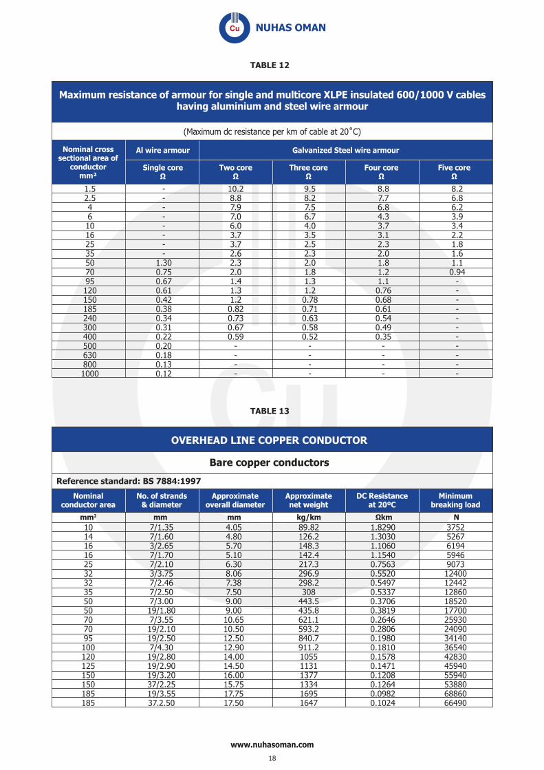
Maximum resistance of armour for single and multicore XLPE insulated 600/1000 V cableshaving aluminium and steel wire armour
Nominal crosssectional area of
conductormm²
Al wire armour
Single core Two core Three core Four core Five core
Galvanized Steel wire armour
1.5 - 10.2 9.5 8.8 8.2 2.5 - 8.8 8.2 7.7 6.8 4 - 7.9 7.5 6.8 6.2 6 - 7.0 6.7 4.3 3.9 10 - 6.0 4.0 3.7 3.4 16 - 3.7 3.5 3.1 2.2 25 - 3.7 2.5 2.3 1.8 35 - 2.6 2.3 2.0 1.6 50 1.30 2.3 2.0 1.8 1.1 70 0.75 2.0 1.8 1.2 0.94 95 0.67 1.4 1.3 1.1 - 120 0.61 1.3 1.2 0.76 - 150 0.42 1.2 0.78 0.68 - 185 0.38 0.82 0.71 0.61 - 240 0.34 0.73 0.63 0.54 - 300 0.31 0.67 0.58 0.49 - 400 0.22 0.59 0.52 0.35 - 500 0.20 - - - - 630 0.18 - - - - 800 0.13 - - - - 1000 0.12 - - - -
OVERHEAD LINE COPPER CONDUCTOR
10 7/1.35 4.05 89.82 1.8290 3752 14 7/1.60 4.80 126.2 1.3030 5267 16 3/2.65 5.70 148.3 1.1060 6194 16 7/1.70 5.10 142.4 1.1540 5946 25 7/2.10 6.30 217.3 0.7563 9073 32 3/3.75 8.06 296.9 0.5520 12400 32 7/2.46 7.38 298.2 0.5497 12442 35 7/2.50 7.50 308 0.5337 12860 50 7/3.00 9.00 443.5 0.3706 18520 50 19/1.80 9.00 435.8 0.3819 17700 70 7/3.55 10.65 621.1 0.2646 25930 70 19/2.10 10.50 593.2 0.2806 24090 95 19/2.50 12.50 840.7 0.1980 34140 100 7/4.30 12.90 911.2 0.1810 36540 120 19/2.80 14.00 1055 0.1578 42830 125 19/2.90 14.50 1131 0.1471 45940 150 19/3.20 16.00 1377 0.1208 55940 150 37/2.25 15.75 1334 0.1264 53880 185 19/3.55 17.75 1695 0.0982 68860 185 37.2.50 17.50 1647 0.1024 66490
Bare copper conductors
mm2 mm mm kg/km N
Reference standard: BS 7884:1997
TABLE 12
TABLE 13
Nominalconductor area
No. of strands& diameter
Approximateoverall diameter
Approximatenet weight
DC Resistanceat 20ºC
Minimumbreaking load
www.nuhasoman.com
18

GENERAL CABLE TECHNICAL DATA & RATING FACTORS

TECHNICAL DATAPOWER CABLES - CURRENT RATINGS
Current ratings and voltage drop of single core cables
Copper conductor XLPE insulated armoured/unarmoured cable
Nominal conductor area
In Air In Ground In Duct Approx Voltage drop of 3 Single core cables (3 Phase System)Single Core in Trefoil Single Core
in TrefoilSingle Core in
Trefoil
UNARM ARMRD ARMRD ARMRD Trefoil
mm² A A A A V/A/km
1.5 22 -- -- -- 26.732.5 30 -- -- -- 16.374 39 -- -- -- 10.196 49 -- -- -- 6.8110 67 67 82 78 4.0416 92 92 108 101 2.5625 123 123 139 134 1.6235 146 146 165 154 1.1850 174 180 199 199 0.87870 222 230 244 239 0.62095 275 282 292 281 0.463120 321 328 332 315 0.379150 371 377 371 341 0.326185 430 433 417 376 0.276240 513 510 480 421 0.235300 594 581 536 459 0.212400 692 664 594 488 0.192500 801 751 658 529 0.179630 925 846 723 571 0.168800 1051 919 764 595 0.1621000 1172 997 810 632 0.157
Installation Conditions considered for Current ratings
Ambient air temperature : 50°C
Ground temperature : 35°C
Depth of Laying : 0.50 m
Thermal resistivity of Soil : 1.2 K.m/W
Max permissible operating temperature at rated current : 90°C
The data provided are for guidance only Nuhas reserve the rights to edit/modify any or whole of the data as a part of their effort of continuous Research & Development
www.nuhasoman.com
20
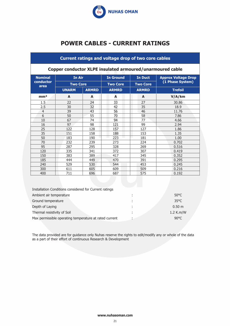
POWER CABLES - CURRENT RATINGS
Current ratings and voltage drop of two core cables
Copper conductor XLPE insulated armoured/unarmoured cable
Nominal conductor
area
In Air In Ground In Duct Approx Voltage Drop (1 Phase System)
Two Core Two Core Two Core
UNARM ARMRD ARMRD ARMRD Trefoil
mm² A A A A V/A/km
1.5 22 24 33 27 30.862.5 30 32 42 35 18.94 39 43 56 46 11.766 50 55 70 58 7.8610 67 74 94 77 4.6616 97 98 121 99 2.9425 122 128 157 127 1.8635 151 158 188 153 1.3550 183 190 223 181 1.0070 232 239 273 224 0.70295 287 295 328 269 0.516120 335 341 372 307 0.419150 383 389 417 345 0.352185 444 449 470 391 0.295240 529 530 544 453 0.245300 611 605 609 509 0.216400 711 696 687 575 0.192
Installation Conditions considered for Current ratings
Ambient air temperature : 50°C
Ground temperature : 35°C
Depth of Laying : 0.50 m
Thermal resistivity of Soil : 1.2 K.m/W
Max permissible operating temperature at rated current : 90°C
The data provided are for guidance only Nuhas reserve the rights to edit/modify any or whole of the data as a part of their effort of continuous Research & Development
www.nuhasoman.com
21

POWER CABLES - CURRENT RATINGS
Current ratings and voltage drop of three and four core cables
Copper conductor XLPE insulated armoured/unarmoured cable
Nominal conductor area
In Air In Ground In Duct Approx Voltage Drop (3 Phase System)
UNARM ARMRD ARMRD ARMRD Trefoil
mm² A A A A V/A/km
1.5 19 20 28 22 26.732.5 27 27 36 29 16.374 34 37 47 39 10.196 44 46 59 48 6.8110 58 64 79 65 4.0416 83 83 102 83 2.5525 105 109 131 107 1.6135 129 134 157 128 1.1750 157 163 187 152 0.8770 200 205 229 187 0.60895 246 253 274 226 0.447120 288 293 312 258 0.363150 330 335 349 291 0.305185 381 386 394 329 0.256240 454 456 455 380 0.212300 524 519 509 427 0.187400 608 597 574 490 0.167
Installation Conditions considered for Current ratings
Ambient air temperatureGround temperatureDepth of LayingThermal resistivity of SoilMax permissible operating temperature at rated current
: 50°C
: 35°C
: 0.50 m
: 1.2 K.m/W
: 90°C
The data provided are for guidance only Nuhas reserve the rights to edit/modify any or whole of the data as a part of their effort of continuous Research & Development
www.nuhasoman.com
22

POWER CABLES - CURRENT RATINGS
Current ratings and voltage drop of Single core cables
Copper conductor PVC insulated armoured/unarmoured cable
Nominal conductor area
In Air In Ground In Duct Approx Voltage drop of 3 Single core cables
(3 Phase System)
Single Core in Trefoil Single Core in Trefoil
Single Core in Trefoil
UNARM ARMRD ARMRD ARMRD Trefoil
mm² A A A A V/A/km
1.5 16 -- -- -- 25.12.5 22 -- -- -- 15.44 29 -- -- -- 9.66 36 -- -- -- 6.410 49 49 68 64 3.816 67 67 89 84 2.425 90 90 115 111 1.535 107 107 136 127 1.150 123 129 162 159 0.8370 156 163 198 193 0.58795 194 200 238 226 0.442120 226 232 270 249 0.365150 260 265 301 274 0.314185 302 303 338 300 0.268240 360 356 388 335 0.229300 415 407 434 367 0.206400 484 462 480 391 0.191500 557 520 528 418 0.178630 641 582 577 450 0.166800 726 628 605 470 0.1611000 808 677 638 497 0.156
Installation Conditions considered for Current ratingsAmbient air temperatureGround temperatureDepth of LayingThermal resistivity of Soil Max permissible operating temperature at rated current
: 50°C
: 35°C
: 0.50 m
: 1.2 K.m/W
: 70°C
The data provided are for guidance only Nuhas reserve the rights to edit/modify any or whole of the data as a part of their effort of continuous Research & Development
www.nuhasoman.com
23
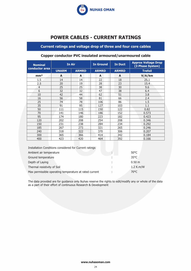
POWER CABLES - CURRENT RATINGS
Current ratings and voltage drop of three and four core cables
Copper conductor PVC insulated armoured/unarmoured cable
Nominal conductor area
In Air In Ground In Duct Approx Voltage Drop (3 Phase System)
UNARM ARMRD ARMRD ARMRD Trefoil
mm² A A A A V/A/km1.5 14 14 22 18 25.12.5 20 19 28 23 15.44 25 25 38 30 9.66 32 32 47 38 6.410 42 44 62 51 3.816 56 58 81 66 2.425 74 78 106 86 1.535 91 95 127 103 1.150 111 115 150 122 0.8270 141 146 186 152 0.57395 174 180 223 182 0.423120 202 208 254 208 0.346150 231 238 284 234 0.292185 267 273 321 265 0.246240 318 322 370 306 0.207300 365 366 414 342 0.184400 423 420 464 392 0.166
Installation Conditions considered for Current ratings
Ambient air temperature
Ground temperature
Depth of Laying
Thermal resistivity of Soil
Max permissible operating temperature at rated current
: 50°C
: 35°C
: 0.50 m
: 1.2 K.m/W
: 70°C
The data provided are for guidance only Nuhas reserve the rights to edit/modify any or whole of the data as a part of their effort of continuous Research & Development
www.nuhasoman.com
24

SHORT CIRCUIT CURRENT RATINGS OF 600/1000 V CABLES COPPER CONDUCTOR, XLPE INSULATION
CALCULATION OF SHORT CIRCUIT CURRENT
Nominal cross sectional Short circuit current area of conductor for 1 sec mm 2 in KA 1.5 0.21 2.5 0.36 4 0.57 6 0.86 10 1.43 16 2.29 25 3.58 35 5.01 50 7.15 70 10.0 95 13.6 120 17.2 150 21.5 185 26.5 240 34.3 300 42.9 400 57.2 500 71.5 630 90.1 800 114.5 1000 143.1
www.nuhasoman.com
25

1000.0 800.0 630.0 500.0 400.0 300.0 240.0 185.0 150.0 120.0 95.0 70.0 50.0
35.0
25.0
16.0
10.0
6.0
4.0
2.5
1.5
1.0 0.75
0.50
0.01
0.10
1.00
10.00
100.00
1000.00
10000.00
0.01 0.1 1 10 Duration of Short Circuit in sec
A k n i t n e r r u
C
t i u c r i c t r o h S
m
m
. q s n i
n o i t c e S
s s o r C
f o
a e r A
NO/TECH/SCCR/XLPE/MDPB/2010
SHORT CIRCUIT CURRENT CHART OF COPPER CONDUCTOR, XLPE INSULATED 600/1000 V CABLES
www.nuhasoman.com
26

RATING FACTORSWhere the conditions of installation are differes from those defi ned
in the Current rating tables, the following rating factors may be used to determine the data for actual installation conditions
RATING FACTORS FOR VARIATION IN AMBIENT TEMPERATUREFOR CABLES LAID IN AIR (FOR INSTALLATION IN AIR ONLY)
Ambient temperature ° C 25 30 35 40 45 50 55
XLPE insulated cables 1.28 1.23 1.18 1.13 1.06 1.00 0.94
PVC insulated cables 1.49 1.40 1.31 1.22 1.11 1.00 0.86
RATING FACTORS FOR VARIATION IN AMBIENT TEMPERATUREFOR CABLES LAID DIRECT IN GROUND OR IN DUCTS
(FOR INSTALLATION IN GROUND & DUCTS ONLY)
Ground temperature ° C 15 20 25 30 35 40 45
XLPE insulated cables 1.16 1.13 1.08 1.03 1.00 0.95 0.90
PVC insulated cables 1.25 1.19 1.12 1.06 1.00 0.92 0.85
RATING FACTORS FOR DEPTH OF LAYING FOR CABLES LAID DIRECT IN GROUND OR IN DUCTS
(FOR INSTALLATION IN GROUND & DUCTS ONLY)
Depth of Laying Cables Laid Direct in Ground Cables Laid in Ducts
Metre Upto 50mm2 70 mm² to 300mm2 Above 300 mm2 Single Core Multicore
0.75 0.975 0.965 0.947 0.957 0.982
0.8 0.970 0.960 0.940 0.950 0.980
1.0 0.950 0.930 0.920 0.930 0.960
1.25 0.940 0.920 0.890 0.910 0.950
1.5 0.930 0.900 0.870 0.890 0.940
1.75 0.920 0.890 0.860 0.880 0.940
2.0 0.910 0.880 0.850 0.870 0.930
2.5 0.900 0.870 0.840 0.860 0.920
3 or more 0.890 0.850 0.820 0.850 0.910
www.nuhasoman.com
27

(FOR INSTALLATION IN GROUND ONLY)RATING FACTORS FOR VARIATION IN THERMAL RESISTIVITY OF SOIL FOR TWO
OR THREE SINGLE-CORE CABLES LAID DIRECT IN THE GROUND
Nominal Area of Conductor mm²
Thermal Resistivity of Soil in K.m/W
0.7 0.8 0.9 1.0 1.2 1.5 2.0 2.5 3.0 3.5 4.0
Up to 50 1.21 1.16 1.11 1.07 1.0 0.91 0.81 0.73 0.68 0.63 0.59
70 1.22 1.16 1.12 1.07 1.0 0.91 0.81 0.73 0.68 0.63 0.59
95 1.22 1.16 1.12 1.07 1.0 0.91 0.81 0.73 0.68 0.63 0.59
120 1.22 1.16 1.12 1.07 1.0 0.91 0.81 0.73 0.68 0.63 0.59
150 1.22 1.16 1.12 1.07 1.0 0.91 0.81 0.73 0.68 0.63 0.59
185 1.22 1.17 1.12 1.07 1.0 0.91 0.81 0.73 0.68 0.62 0.59
240 1.23 1.17 1.12 1.07 1.0 0.91 0.80 0.73 0.68 0.62 0.59
300 1.23 1.17 1.12 1.07 1.0 0.91 0.80 0.73 0.68 0.62 0.59
400 1.23 1.17 1.12 1.07 1.0 0.91 0.80 0.73 0.67 0.62 0.58
500 1.23 1.17 1.12 1.07 1.0 0.91 0.80 0.73 0.67 0.62 0.58
630 1.23 1.17 1.12 1.07 1.0 0.91 0.80 0.73 0.67 0.61 0.58
800 1.23 1.17 1.12 1.07 1.0 0.91 0.80 0.72 0.66 0.61 0.58
1000 1.24 1.18 1.12 1.07 1.0 0.91 0.80 0.72 0.66 0.61 0.58
(FOR INSTALLATION IN GROUND ONLY)RATING FACTORS FOR VARIATION IN THERMAL RESISTIVITY OF SOIL FOR TWIN
OR MULTI CORE CABLES LAID DIRECT IN THE GROUND
Nominal Area of Conductor mm²
Thermal Resistivity of Soil in K.m/W
0.7 0.8 0.9 1.0 1.2 1.5 2.0 2.5 3.0 3.5 4.0
1.5/2.5 1.12 1.09 1.07 1.04 1.0 0.94 0.86 0.80 0.75 0.70 0.66
4 1.13 1.10 1.07 1.05 1.0 0.94 0.85 0.79 0.74 0.69 0.65
6 1.14 1.10 1.07 1.05 1.0 0.93 0.85 0.79 0.74 0.68 0.64
10 1.15 1.11 1.08 1.05 1.0 0.93 0.85 0.78 0.73 0.67 0.63
16 1.16 1.12 1.08 1.05 1.0 0.93 0.84 0.77 0.72 0.66 0.62
25 1.17 1.13 1.09 1.05 1.0 0.93 0.83 0.77 0.71 0.65 0.61
35 1.17 1.13 1.09 1.06 1.0 0.92 0.83 0.76 0.71 0.65 0.61
50 1.17 1.13 1.09 1.06 1.0 0.92 0.83 0.76 0.71 0.65 0.61
70 1.18 1.14 1.09 1.06 1.0 0.92 0.83 0.75 0.70 0.64 0.60
95 1.18 1.14 1.09 1.06 1.0 0.92 0.83 0.75 0.70 0.64 0.60
120 1.19 1.14 1.10 1.06 1.0 0.92 0.82 0.75 0.69 0.64 0.60
150 1.19 1.14 1.10 1.06 1.0 0.92 0.82 0.75 0.69 0.63 0.59
185 1.19 1.14 1.10 1.06 1.0 0.92 0.82 0.74 0.69 0.63 0.59
240 1.20 1.15 1.10 1.07 1.0 0.92 0.81 0.74 0.69 0.63 0.59
300 1.20 1.15 1.10 1.07 1.0 0.92 0.81 0.74 0.69 0.63 0.59
400 1.20 1.15 1.10 1.07 1.0 0.92 0.81 0.74 0.69 0.63 0.59
www.nuhasoman.com
28

(FOR INSTALLATION IN DUCT ONLY)RATING FACTORS FOR VARIATION IN THERMAL RESISTIVITY OF SOIL FOR TWO
OR THREE SINGLE-CORE CABLES LAID IN DUCT
Nominal Area of Conductor mm²
Thermal Resistivity of Soil in K.m/W
0.7 0.8 0.9 1.0 1.2 1.5 2.0 2.5 3.0 3.5 4.0
Up to 50 1.11 1.08 1.06 1.04 1.0 0.94 0.87 0.82 0.77 0.73 0.69
70 1.12 1.09 1.06 1.04 1.0 0.94 0.87 0.81 0.76 0.72 0.68
95 1.12 1.09 1.06 1.04 1.0 0.94 0.87 0.81 0.76 0.72 0.68
120 1.13 1.10 1.07 1.04 1.0 0.94 0.86 0.80 0.75 0.72 0.67
150 1.13 1.10 1.07 1.04 1.0 0.94 0.86 0.80 0.75 0.71 0.67
185 1.13 1.10 1.07 1.04 1.0 0.93 0.86 0.79 0.75 0.70 0.67
240 1.14 1.11 1.07 1.04 1.0 0.93 0.86 0.79 0.74 0.70 0.66
300 1.14 1.11 1.08 1.05 1.0 0.93 0.85 0.79 0.74 0.69 0.65
400 1.14 1.11 1.08 1.05 1.0 0.93 0.85 0.78 0.73 0.68 0.65
500 1.15 1.11 1.08 1.05 1.0 0.93 0.85 0.78 0.73 0.68 0.64
630 1.15 1.12 1.08 1.05 1.0 0.93 0.84 0.78 0.72 0.68 0.64
800 1.16 1.12 1.09 1.05 1.0 0.93 0.84 0.77 0.72 0.67 0.64
1000 1.16 1.13 1.09 1.05 1.0 0.92 0.84 0.77 0.71 0.67 0.63
(FOR INSTALLATION IN DUCT ONLY)RATING FACTORS FOR VARIATION IN THERMAL RESISTIVITY OF SOIL FOR TWIN
OR MULTI-CORE CABLES LAID IN SINGLE-WAY DUCTS
Nominal Area of Conductor mm²
Thermal Resistivity of Soil in K.m/W
0.7 0.8 0.9 1.0 1.2 1.5 2.0 2.5 3.0 3.5 4.0
1.5/2.5 1.04 1.03 1.02 1.02 1.0 0.98 0.94 0.91 0.88 0.86 0.83
4 1.04 1.04 1.03 1.02 1.0 0.97 0.94 0.90 0.87 0.85 0.82
6 1.05 1.04 1.03 1.02 1.0 0.97 0.93 0.90 0.86 0.84 0.81
10 1.05 1.04 1.03 1.02 1.0 0.97 0.93 0.89 0.86 0.83 0.80
16 1.06 1.04 1.03 1.02 1.0 0.97 0.92 0.88 0.85 0.82 0.79
25 1.06 1.05 1.03 1.02 1.0 0.96 0.92 0.88 0.84 0.82 0.78
35 1.06 1.05 1.03 1.02 1.0 0.96 0.92 0.87 0.83 0.81 0.77
50 1.07 1.05 1.03 1.02 1.0 0.96 0.91 0.87 0.83 0.80 0.77
70 1.07 1.05 1.04 1.02 1.0 0.96 0.91 0.86 0.82 0.79 0.76
95 1.07 1.06 1.04 1.02 1.0 0.96 0.91 0.86 0.82 0.78 0.75
120 1.08 1.06 1.04 1.03 1.0 0.95 0.90 0.85 0.81 0.78 0.74
150 1.09 1.06 1.04 1.03 1.0 0.95 0.90 0.85 0.80 0.77 0.73
185 1.09 1.07 1.05 1.03 1.0 0.95 0.89 0.84 0.80 0.76 0.72
240 1.09 1.07 1.05 1.03 1.0 0.95 0.89 0.84 0.79 0.76 0.72
300 1.10 1.07 1.05 1.03 1.0 0.95 0.88 0.83 0.78 0.75 0.71
400 1.10 1.07 1.05 1.03 1.0 0.95 0.88 0.83 0.78 0.75 0.71
www.nuhasoman.com
29

(FOR INSTALLATION IN GROUND ONLY)GROUP RATING FACTORS FOR MORE THAN ONE TWIN OR MULTI-CORE ARMOURED OR UNARMOURED CABLES IN HORIZONTAL FORMATION LAID IN DIRECT GROUND.
No. of cables 2 3 4 5 6 7 8 9 10 11 12
Cables laid touching 0.81 0.70 0.63 0.59 0.55 0.52 0.50 0.48 0.47 0.45 0.44
Cables laid 15 cm apart 0.87 0.78 0.74 0.70 0.68 0.66 0.64 0.63 0.62 0.61 0.60
Cables laid 30 cm apart 0.91 0.84 0.81 0.78 0.77 0.75 0.75 0.74 0.73 0.73 0.72
Cables laid 45 cm apart 0.93 0.88 0.86 0.84 0.83 0.82 0.81 0.81 0.80 0.80 0.80
Cables laid 60 cm apart 0.95 0.90 0.89 0.87 0.87 0.86 0.86 0.85 0.85 0.85 0.84
(FOR INSTALLATION IN GROUND ONLY)GROUP RATING FACTORS FOR MORE THAN ONE CIRCUITS OF 3 SINGLE CORE ARMOURED OR UNARMOURED
CABLES IN TREFOIL TOUCHING,HORIZONTAL FORMATION LAID IN DIRECT GROUND
No. of cables 2 3 4 5 6 7 8 9 10 11 12
Cables laid touching 0.78 0.66 0.61 0.56 0.53 0.50 0.49 0.47 0.46 0.44 0.43
Cables laid 15 cm apart 0.83 0.73 0.68 0.64 0.61 0.59 0.57 0.56 0.55 0.54 0.53
Cables laid 30 cm apart 0.88 0.79 0.73 0.73 0.71 0.69 0.68 0.67 0.67 0.66 0.66
Cables laid 45 cm apart 0.91 0.84 0.81 0.79 0.78 0.76 0.76 0.75 0.75 0.74 0.74
Cables laid 60 cm apart 0.93 0.87 0.85 0.83 0.82 0.82 0.81 0.81 0.80 0.80 0.80
(FOR INSTALLATION IN DUCT ONLY)GROUP RATING FACTORS FOR MORE THAN ONE TWIN OR MULTI-CORE ARMOURED OR UNARMOURED CABLES
IN HORIZONTAL FORMATION LAID IN SINGLE WAY DUCTS
No. of cables 2 3 4 5 6 7 8 9 10 11 12
Cables laid touching 0.90 0.83 0.79 0.75 0.73 0.71 0.70 0.68 0.67 0.66 0.66
Cables laid 30 cm apart 0.93 0.88 0.85 0.83 0.82 0.81 0.80 0.79 0.79 0.78 0.78
Cables laid 45 cm apart 0.95 0.91 0.89 0.88 0.87 0.86 0.85 0.85 0.85 0.84 0.84
Cables laid 60 cm apart 0.96 0.93 0.92 0.91 0.90 0.89 0.89 0.89 0.89 0.88 0.88
(FOR INSTALLATION IN DUCT ONLY)GROUP RATING FACTORS FOR MORE THAN ONE CIRCUITS OF 3 SINGLE CORE ARMOURED OR UNARMOURED
CABLES IN TREFOIL TOUCHING ,HORIZONTAL FORMATION LAID IN SINGLE WAY DUCTS
No. of cables 2 3 4 5 6 7 8 9 10 11 12
Cables laid touching 0.87 0.78 0.74 0.70 0.69 0.67 0.66 0.65 0.64 0.63 0.63
Cables laid 45 cm apart 0.91 0.84 0.81 0.79 0.78 0.76 0.76 0.75 0.75 0.74 0.74
Cables laid 60 cm apart 0.93 0.87 0.85 0.83 0.82 0.82 0.81 0.81 0.80 0.80 0.80
www.nuhasoman.com
30

(FOR INSTALLATION IN AIR ONLY)GROUP RATING FACTORS FOR GROUPS OF MORE THAN ONE MULTI-CORE CABLE IN AIR - TO BE APPLIED TO THE
CURRENT-CARRYING CAPACITY FOR ONE MULTI-CORE CABLE IN FREE AIR
Method of Installation Number of Trays
Number of cables
1 2 3 4 6 9
Cables on perforated trays
1 1.00 0.88 0.82 0.79 0.76 0.73
2 1.00 0.87 0.80 0.77 0.73 0.68
3 1.00 0.86 0.79 0.76 0.71 0.66
1 1.00 1.00 0.98 0.95 0.91 -
2 1.00 0.99 0.96 0.92 0.87 -
3 1.00 0.98 0.95 0.91 0.85 -
Cables on vertical perforated trays
1 1.00 0.88 0.82 0.78 0.73 0.72
2 1.00 0.88 0.81 0.76 0.71 0.70
1 1.00 0.91 0.89 0.88 0.87 -
2 1.00 0.91 0.88 0.87 0.85 -
Cables on laddersupports, cleats, etc
1 1.00 0.87 0.82 0.80 0.79 0.78
2 1.00 0.86 0.80 0.78 0.76 0.73
3 1.00 0.85 0.79 0.76 0.73 0.70
1 1.00 1.00 1.00 1.00 1.00 -
2 1.00 0.99 0.98 0.97 0.96 -
3 1.00 0.98 0.97 0.96 0.93 -
Note 1: Values are given for vertical spacings between trays of 300 mm. For closer spacing, the factors should be reduced.Note 2: Values are given for horizontal spacing between trays of 225 mm with trays mounted back to back. For closer spacing, the factors should be reduced.Note 3: For circuits having more than one cable in parallel per phase, each three phase set of conductors should be considered as a circuit for the purpose of this table.
www.nuhasoman.com
31

(FOR INSTALLATION IN AIR ONLY)GROUP RATING FACTORS FOR GROUPS OF MORE THAN ONE CIRCUIT OF SINGLE CORE CABLES TO BE APPLIED
TO THE CURRENT-CARRYING CAPACITY FOR ONE CIRCUIT OF SINGLE-CORE CABLES IN FREE AIR
Method of InstallationNumber
of Trays
Number of three-phase
circuits (Note 3)Use as a
multiplier torating for
1 2 3
Cables on perforated trays
1 1.00 0.98 0.96
Three cables intrefoil formation
2 0.97 0.93 0.89
3 0.96 0.92 0.86
Cables on vertical perforated trays
1 1.00 0.91 0.89
2 1.00 0.90 0.86
Cables on laddersupports, cleats, etc
1 1.00 1.00 1.00
2 0.97 0.95 0.93
3 0.96 0.94 0.90
Note 1: Values are given for vertical spacings between trays of 300 mm. For closer spacing, the factors should be reduced.
Note 2: Values are given for horizontal spacing between trays of 225 mm with trays mounted back to back. For closer spacing, the factors should be reduced.
Note 3: For circuits having more than one cable in parallel per phase, each three phase set of conductors should be considered as a circuit for the purpose of this table.
Recommended Minimum Bending Radius for Installation
XLPE Insulated LV Cable PVC Sheath LSOH Sheath
Single Core 8D 16D
Multi Core 8D 16D
www.nuhasoman.com
32

NO/MKT/CAT/001/Rev 3
Date 10/04/2021
NUHAS OMAN LLCP O Box 186, Postal Code 124,
Rusayl Industrial Estate, Sultanate of OmanTel : +968-24449007, 24449247, 24449249 Fax : +968 24446790
Email : [email protected] Website:www.nuhasoman.com
(A Member of the Al Bahja Group)AN ISO 9001: 2015 COMPANY