Embed Size (px)
Citation preview
4th CIMAC CASCADES, London, 20140314, S. Murakami
Potentials for Efficiency Improvement of
Gas Engines
1
Dr. Shinsuke Murakami Development Engineer
Commercial and Large Engines
Engineering and Technology Powertrain Systems
4th CIMAC CASCADES, London, 20140314, S. Murakami Public
Content
2
Examples of AVL Gas Engine Projects for Efficiency Improvement
Potentials for Further Efficiency Improvement
Summary and Conclusion
“Fuel Efficiency – Are Improvements Possible?”

4th CIMAC CASCADES, London, 20140314, S. Murakami Public
Example 1
High speed gas engine 1500 rpm
Open chamber combustion concept with pre-chamber spark plug
Targets
Efficiency increase by 2.7 % points
BMEP increase by 3.4 bar
THC 1200 mg/Nm3 at 3 % O2
NOx TA-Luft
Tasks
SCE testing (set-up and commissioning + 5.5 months testing)
CFD simulations for optimization of charge motion and piston bowl geometry
Results
All targets achieved
Efficiency increased by 2.8 % points
Examples of AVL Gas Engine Projects
3

4th CIMAC CASCADES, London, 20140314, S. Murakami Public 4
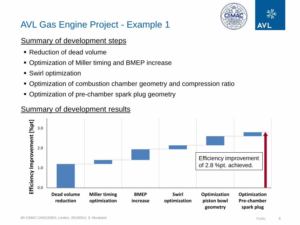
Summary of development steps
Reduction of dead volume
Optimization of Miller timing and BMEP increase
Swirl optimization
Optimization of combustion chamber geometry and compression ratio
Optimization of pre-chamber spark plug geometry
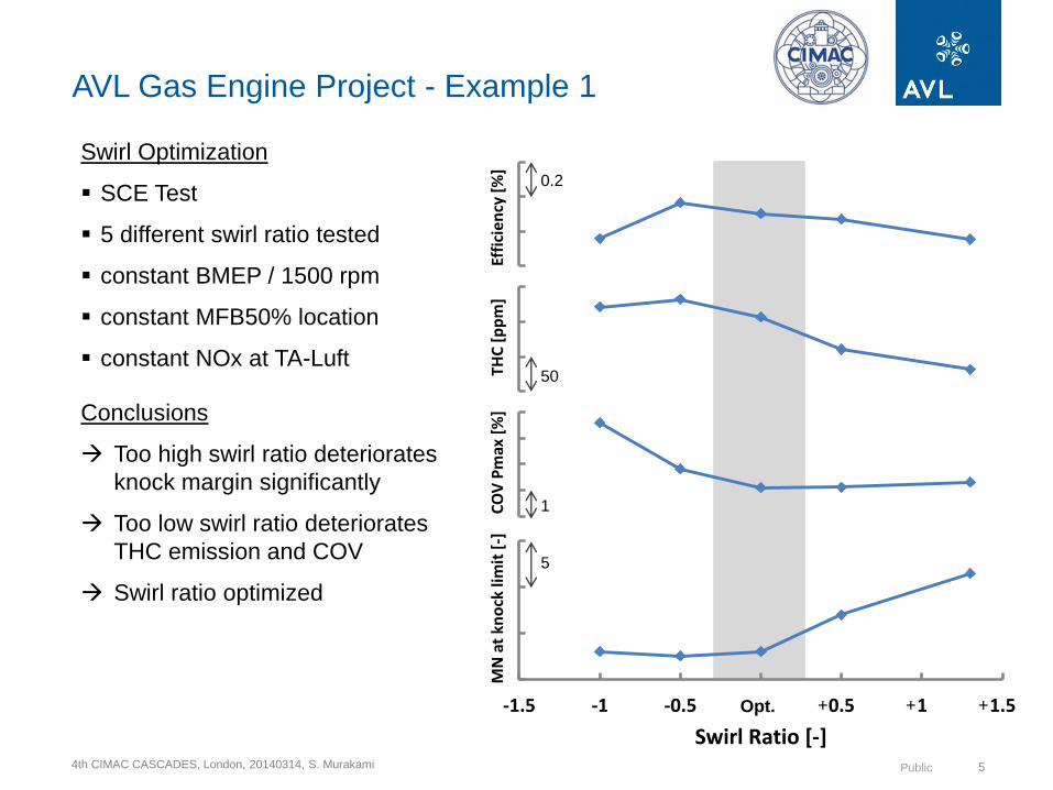
AVL Gas Engine Project - Example 1
Reduction of Dead Volume Miller Timing and BMEP
Effi
cie
ncy
[%
]
BMEP [bar]
1 bar
0.2 %pt
knock limit
base IVC
Effi
cie
ncy
[%
]
BMEP [bar]
1 bar
0.2 %pt knock limit
IVC 20° adv.
knock limit
base IVC
4th CIMAC CASCADES, London, 20140314, S. Murakami Public 5
AVL Gas Engine Project - Example 1
5
1
50
0.2
+ + +
CO
V P
max
[%
]TH
C [
pp
m]
Effi
cien
cy [
%]
-1.5 -1 -0.5 0 0.5 1 1.5
MN
at
kno
ck li
mit
[-]
Swirl Ratio [-]
Opt.
Swirl Optimization
SCE Test
5 different swirl ratio tested
constant BMEP / 1500 rpm
constant MFB50% location
constant NOx at TA-Luft
Conclusions
Too high swirl ratio deteriorates
knock margin significantly
Too low swirl ratio deteriorates
THC emission and COV
Swirl ratio optimized

4th CIMAC CASCADES, London, 20140314, S. Murakami Public
CFD
Measurement
Piston A Piston C
Piston A
Piston B
Piston C
Piston D
Piston E
AVL Gas Engine Project - Example 1
6
Optimization of Piston Bowl Geometry
Pre-optimization by CFD
SCE Test
4 bowl shapes tested
4 compression ratios tested
constant BMEP / 1500 rpm
constant NOx at TA-Luft
Conclusions
Piston contour to be matched
with the half-spherical flame
propagation
Minimize piston to head
clearance to enhance squish
flow effect
Piston bowl design and
compression ratio optimized
4th CIMAC CASCADES, London, 20140314, S. Murakami Public
AVL Gas Engine Project - Example 1
7
-0.8
-0.6
-0.4
-0.2
0
0.2
0.4
Base A B C D E F G H I
ΔEf
fici
ency
, ΔCO
V IM
EP [%
pt.]
Pre-chamber spark plug variants
Efficiency CoV IMEP
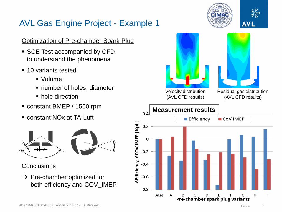
Measurement results
Velocity distribution
(AVL CFD resutls)
Residual gas distribution
(AVL CFD results)
Optimization of Pre-chamber Spark Plug
SCE Test accompanied by CFD
to understand the phenomena
10 variants tested
Volume
number of holes, diameter
hole direction
constant BMEP / 1500 rpm
constant NOx at TA-Luft
Conclusions
Pre-chamber optimized for
both efficiency and COV_IMEP
4th CIMAC CASCADES, London, 20140314, S. Murakami Public
0.0
1.0
2.0
3.0
Dead volumereduction
Miller timingoptimization
BMEPincrease
Swirloptimization
Optimizationpiston bowlgeometry
OptimizationPre-chamber
spark plug
Effi
cie
ncy
Imp
rove
me
nt
[%p
t]
8
Summary of development steps
Reduction of dead volume
Optimization of Miller timing and BMEP increase
Swirl optimization
Optimization of combustion chamber geometry and compression ratio
Optimization of pre-chamber spark plug geometry
Summary of development results
Efficiency improvement
of 2.8 %pt. achieved.
AVL Gas Engine Project - Example 1

4th CIMAC CASCADES, London, 20140314, S. Murakami Public
Example 2
Medium Speed Gas Engine 750 rpm
Fuel-fed pre-chamber with spark ignition
Targets
Efficiency increase by 2 % points
COV_Pmax reduction from 5~6 % to 3 %
NOx TA-Luft
Tasks
SCE and MCE testing support
CFD simulations for optimization of piston bowl and pre-chamber geometries
Results
COV_Pmax significantly reduced
Efficiency increase by 2.1 % points
Examples of AVL Gas Engine Projects
9

4th CIMAC CASCADES, London, 20140314, S. Murakami Public 10
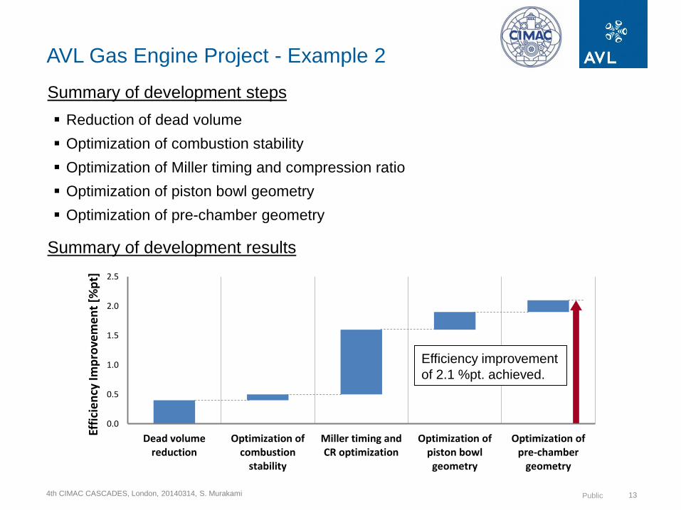
Summary of development steps
Reduction of dead volume
Optimization of combustion stability
Optimization of Miller timing and compression ratio
Optimization of piston bowl geometry
Optimization of pre-chamber geometry
AVL Gas Engine Project - Example 2
Optimization of combustion stability Miller Timing and Compression Ratio
Design PFP limit
Higher ave.
PFP possible
SCE test result | constant BMEP | same ave. PFP
0.2 %pt
SCE test result
constant BMEP
4th CIMAC CASCADES, London, 20140314, S. Murakami Public
AVL Gas Engine Project - Example 2
11
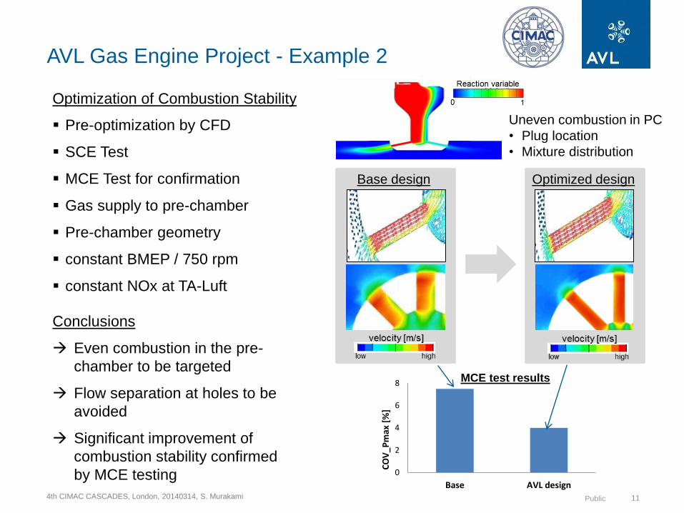
Optimization of Combustion Stability
Pre-optimization by CFD
SCE Test
MCE Test for confirmation
Gas supply to pre-chamber
Pre-chamber geometry
constant BMEP / 750 rpm
constant NOx at TA-Luft
Conclusions
Even combustion in the pre-
chamber to be targeted
Flow separation at holes to be
avoided
Significant improvement of
combustion stability confirmed
by MCE testing
Uneven combustion in PC
• Plug location
• Mixture distribution
Base design Optimized design
0
2
4
6
8
Base AVL design
CO
V_P
max
[%
]MCE test results

4th CIMAC CASCADES, London, 20140314, S. Murakami Public
AVL Gas Engine Project - Example 2
12
Optimization of Piston Bowl Geometry
Pre-optimization by CFD
SCE Test
MCE Test for confirmation
3 bowl shapes tested
5 compression ratios tested
constant BMEP / 750 rpm
constant NOx at TA-Luft
Conclusions
Piston bowl contour to be
matched with the flame
propagation from the flame jet
out of pre-chamber
Piston bowl to be optimized
together with pre-chamber
nozzle configuration
Measurement
CFD
Optimized Design
Optimum
Cone
Flat
4th CIMAC CASCADES, London, 20140314, S. Murakami Public
0.0
0.5
1.0
1.5
2.0
2.5
Dead volumereduction
Optimization ofcombustion
stability
Miller timing andCR optimization
Optimization ofpiston bowlgeometry
Optimization ofpre-chamber
geometry
Effi
cie
ncy
Imp
rove
me
nt
[%p
t]
13
Summary of development steps
AVL Gas Engine Project - Example 2
Summary of development results
Efficiency improvement
of 2.1 %pt. achieved.
Reduction of dead volume
Optimization of combustion stability
Optimization of Miller timing and compression ratio
Optimization of piston bowl geometry
Optimization of pre-chamber geometry

4th CIMAC CASCADES, London, 20140314, S. Murakami Public
Content
14
Examples of AVL Gas Engine Projects for Efficiency Improvement
Potentials for Further Efficiency Improvement
Summary and Conclusion
4th CIMAC CASCADES, London, 20140314, S. Murakami Public
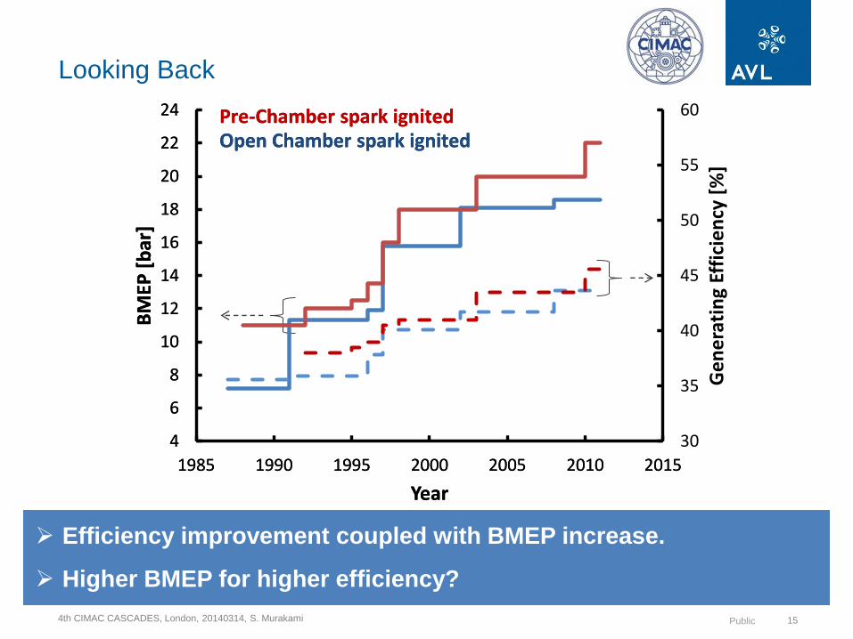
30
35
40
45
50
55
60
4
6
8
10
12
14
16
18
20
22
24
1985 1990 1995 2000 2005 2010 2015
Ge
ne
rati
ng
Effi
cie
ncy
[%
]
BM
EP [
bar
]
Year
Pre-Chamber spark ignited Open Chamber spark ignited
Looking Back
15
Efficiency improvement coupled with BMEP increase.
Higher BMEP for higher efficiency?
30
35
40
45
50
55
60
4
6
8
10
12
14
16
18
20
22
24
1985 1990 1995 2000 2005 2010 2015
Ge
ne
rati
ng
Effi
cie
ncy
[%
]
BM
EP [
bar
]
Year
Pre-Chamber spark ignited Open Chamber spark ignited
4th CIMAC CASCADES, London, 20140314, S. Murakami Public
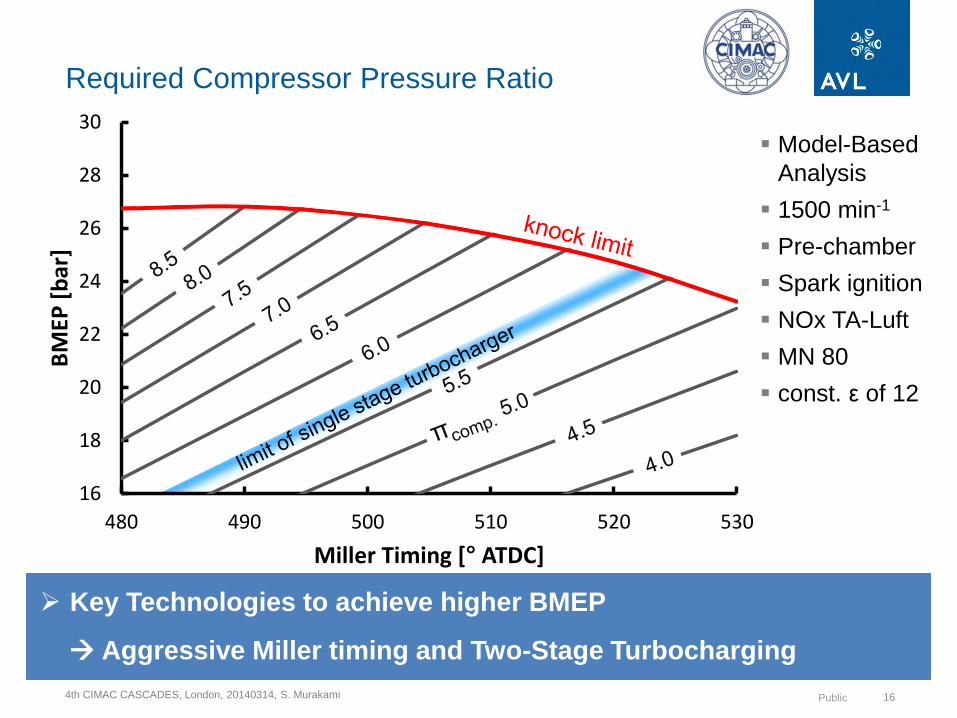
16
18
20
22
24
26
28
30
480 490 500 510 520 530
BM
EP [
bar
]
Miller Timing [° ATDC]
Required Compressor Pressure Ratio
16
Key Technologies to achieve higher BMEP
Aggressive Miller timing and Two-Stage Turbocharging
Model-Based
Analysis
1500 min-1
Pre-chamber
Spark ignition
NOx TA-Luft
MN 80
const. ε of 12

4th CIMAC CASCADES, London, 20140314, S. Murakami Public
45.5
45.75
46
46.25
43.75
44
44.25
44.5
44.75
45
45.25
45.5
45.75
44.5
44.75
45
45.25
45.5
45.75
46
46.25
46.5
46.75
BMEP – Miller – BTE Matrix at const. ε
17
BTE
16
18
20
22
24
26
28
30
480 490 500 510 520 530
BM
EP [
bar
]
Miller Timing [° ATDC]
Model-Based
Analysis
1500 min-1
Pre-chamber
Spark ignition
NOx TA-Luft
MN 80
const. ε of 12
The higher the BMEP, the higher the efficiency at constant ε.

4th CIMAC CASCADES, London, 20140314, S. Murakami Public
45.0
45.5
46.0
46.5
21 22 23 24 25 26
Bra
ke T
he
rmal
Eff
icie
ncy
[%
]
BMEP [bar]
SCE Result | BMEP Variation with two different ε
18
knock limit
ε low
ε high
SCE Test
Results
1500 min-1
Pre-chamber
Spark ignition
NOx TA-Luft
MN80
The higher the BMEP the higher the knock limited efficiency.

4th CIMAC CASCADES, London, 20140314, S. Murakami Public
1010.5
11
11.5
12
12.5
13
13.5
14
14.5
15
15.5
11
11.5
12
12.5
13
13.5
14
14.5
15
19
16
18
20
22
24
26
28
30
480 490 500 510 520 530
BM
EP [
bar
]
Miller Timing [° ATDC]
ε
BMEP – Miller – ε Matrix at Knock Limit
Model-Based
Analysis
1500 min-1
Pre-chamber
Spark ignition
NOx TA-Luft
MN 80
ε at knock limit
High BMEP with low ε or high ε with low BMEP?

4th CIMAC CASCADES, London, 20140314, S. Murakami Public
45.2
45.4
45.6
45.8
46
46.2
46.3
44.8
45.2
45.2
45.4
45.4
45.6
45.8
46
46.2
46.3
44.8
45
45
45.2
45.2
45.3
45.3
BMEP – Miller – BTE Matrix at Knock Limit
20
16
18
20
22
24
26
28
30
480 490 500 510 520 530
BM
EP [
bar
]
Miller Timing [° ATDC]
BTE
Model-Based
Analysis
1500 min-1
Pre-chamber
Spark ignition
NOx TA-Luft
MN 80
ε at knock limit
Optimum BMEP Target for the highest efficiency 24 – 26 bar
Design PFP requirement of 250 bar
4th CIMAC CASCADES, London, 20140314, S. Murakami Public
Content
21
Examples of AVL Gas Engine Projects for Efficiency Improvement
Potentials for Further Efficiency Improvement
Summary and Conclusion

4th CIMAC CASCADES, London, 20140314, S. Murakami Public
Summary
22
Examples of AVL Gas Engine Projects for Efficiency Improvement
were reviewed.
Incremental development will result in “Many a little makes a mickle.”
CFD Simulation and SCE Testing are effective for rapid development.
Key Enablers for the further efficiency improvement are;
High BMEP of 24 – 26 bar
Aggressive Miller Timing
Two-stage turbocharging
High PFP capability

4th CIMAC CASCADES, London, 20140314, S. Murakami Public
Conclusion
23
“Fuel Efficiency – Are Improvements Possible?”
“Where there is a will, there is a way!”
4th CIMAC CASCADES, London, 20140314, S. Murakami Public 24
Thank you for your attention!


![Man Common Rail Cimac[1]](https://img.pdfslide.us/doc/110x75/55028ba64a7959c0558b52cd/man-common-rail-cimac1.jpg)