Embed Size (px)
Citation preview
Potential of glassy carbon and siliconcarbide photonic structures as
electromagnetic radiation shields foratmospheric re-entry
Nikolay Komarevskiy,1,* Valery Shklover,1 Leonid Braginsky,1
Christian Hafner,1 and John Lawson2
1Swiss Federal Institute of Technology (ETH) Zurich, 8092 Zurich, Switzerland2MS-234-1, NASA Ames Research Center, Moffett Field, California 94035, USA
Abstract: During high-velocity atmospheric entries, space vehicles canbe exposed to strong electromagnetic radiation from ionized gas in theshock layer. Glassy carbon (GC) and silicon carbide (SiC) are candidatethermal protection materials due to their high melting point and also theirgood thermal and mechanical properties. Based on data from shock tube ex-periments, a significant fraction of radiation at hypersonic entry conditionsis in the frequency range from 215 to 415 THz. We propose and analyzeSiC and GC photonic structures to increase the reflection of radiation in thatrange. For this purpose, we performed numerical optimizations of variousstructures using an evolutionary strategy. Among the considered structuresare layered, porous, woodpile, inverse opal and guided-mode resonancestructures. In order to estimate the impact of fabrication inaccuracies,the sensitivity of the reflectivity to structural imperfections is analyzed.We estimate that the reflectivity of GC photonic structures is limited to38% in the aforementioned range, due to material absorption. However,GC material can be effective for photonic reflection of individual, strongspectral line. SiC on the other hand can be used to design a good reflectorfor the entire frequency range.
© 2012 Optical Society of America
OCIS codes: (050.5298) Photonic crystals; (350.4600) Optical engineering.
References and links1. J. Joannopoulos, S. Johnson, J. Winn, and R. Meade, Photonic Crystals: Molding the Flow of Light (Princeton
University Press, 2008).2. V. Shklover, L. Braginsky, G. Witz, M. Mishrikey, and C. Hafner, “High-temperature photonic structures. Ther-
mal barrier coatings, infrared sources and other applications,” J. Comput. Theor. Nanosci. 5, 862–893 (2008).3. J. Grinstead, M. Wilder, J. Olejniczak, D. Bogdanoff, G. Allen, K. Dang, and M. Forrest, “Shock-heated air
radiation measurements at Lunar return conditions,” AIAA Pap. 1244, 092407 (2008).4. C. Park, “Stagnation-region heating environment of the Galileo probe,” J. Thermophys. Heat Transfer 23, 417–
424 (2009).5. N. Komarevskiy, L. Braginsky, V. Shklover, C. Hafner, and J. Lawson, “Fast numerical methods for the design
of layered photonic structures with rough interfaces,” Opt. Express 19, 5489–5499 (2011).6. N. Komarevskiy, V. Shklover, L. Braginsky, C. Hafner, O. Fabrichnaya, S. White, and J. Lawson, “Design of
reflective, photonic shields for atmospheric reentry,” J. Electromagn. Anal. Appl. 3, 228–237 (2011).
#165159 - $15.00 USD Received 21 Mar 2012; accepted 17 May 2012; published 11 Jun 2012(C) 2012 OSA 18 June 2012 / Vol. 20, No. 13 / OPTICS EXPRESS 14189
7. A. Brandis, C. Johnston, B. Cruden, D. Prabhu, and D. Bose, “Uncertainty analysis of Neqair and Hara predic-tions of air radiation measurements obtained in the East facility,” in 42nd AIAA Thermophysics Conference,(American Institute of Aeronautics & Astronautics (AIAA), 2011), pp. 1–14.
8. Directionality can be obtained from simulation sets that are calibrated against shock tube data.9. L. Li, “Formulation and comparison of two recursive matrix algorithms for modeling layered diffraction grat-
ings,” J. Opt. Soc. Am. A 13, 1024–1035 (1996).10. D. Whittaker and I. Culshaw, “Scattering-matrix treatment of patterned multilayer photonic structures,”
Phys. Rev. B 60, 2610–2618 (1999).11. J. Frohlich, “Evolutionary Optimization for Computational Electromagnetics,” Ph.D. thesis (ETH Zurich, IFH
Laboratory, 1997).12. [Online]. Available: http://www.sopra-sa.com/13. E. D. Palik, Handbook of Optical Constants of Solids (Academic Press, 1998).14. M. Williams and E. Arakawa, “Optical properties of glassy carbon from 0 to 82 eV,” J. Appl. Phys. 43, 3460–3463
(1972).15. J. Shor, I. Grimberg, B. Weiss, and A. Kurtz, “Direct observation of porous SiC formed by anodization in HF,”
Appl. Phys. Lett. 62, 2836–2838 (1993).16. There is no mathematical proof for this observation, but it seems reasonable from the physical point of view,
since no scattering occurs at planar interfaces.17. A. Zakhidov, R. Baughman, Z. Iqbal, C. Cui, I. Khayrullin, S. Dantas, J. Marti, and V. Ralchenko, “Carbon
structures with three-dimensional periodicity at optical wavelengths,” Science 282, 897–901 (1998).18. S. Wang and R. Magnusson, “Theory and applications of guided-mode resonance filters,” Appl. Opt. 32, 2606–
2613 (1993).19. M. Gale, K. Knop, and R. Morf, “Zero-order diffractive microstructures for security applications,” Proc. SPIE
1210, 83–89 (1990).20. Z. Liu, S. Tibuleac, D. Shin, P. Young, and R. Magnusson, “High-efficiency guided-mode resonance filter,”
Opt. Lett. 23, 1556–1558 (1998).21. S. Tikhodeev, A. Yablonskii, E. Muljarov, N. Gippius, and T. Ishihara, “Quasiguided modes and optical properties
of photonic crystal slabs,” Phys. Rev. B 66, 045102 (2002).22. L. Braginsky and V. Shklover, “Light propagation in an imperfect photonic crystal,” Phys. Rev. B 73, 085107
(2006).
1. Introduction
Practical applications for photonic crystals (PhCs) are vast [1, 2]. The optical response of PhCscan be effectively controlled via structural design. An interesting, but one yet to be practicallyrealized, application of PhCs is as radiation shields for atmospheric re-entry of space vehicles.Electromagnetic radiation from ionized gas in the shock layer can constitute up to 30-50%[3] of the overall heat flux for lunar return trajectories, albeit for relatively short times. ForJupiter entries, on the other hand, most of the heating is radiative [4]. Therefore, in addition toprotection against convective heating, a reentry thermal protection systems (TPS) should alsobe designed for radiation shielding. Ideally, the design should be tuned to the radiative spectraof a specific planet as well as to the specific entry conditions.
The easiest way to design radiation shields for atmospheric re-entry is with layered media[5]. Provided the two constituent materials possess a sufficient dielectric contrast and low ab-sorption, broadband radiation shields with high omnidirectional reflection can be designed [6].However, applications such as atmospheric re-entry impose many additional constraints on thematerial properties (thermal, mechanical, etc.). Therefore, finding a suitable pair of materialscan be very demanding.
Currently, TPS for the most demanding atmospheric re-entries are made of highly porouscarbon based materials. These materials, for example, PICA (phenolic-impregnated carbon ab-lators), possess many of the required thermal and mechanical properties. However, these ma-terials are strong absorbers of radiation and therefore currently offer no protection at all fromradiative heating. On the other hand, if these materials could be structured in such way thathigh reflection is obtained, radiative heating of the vehicle during re-entry could be reduced. Inthis paper we analyze the potential of glassy carbon and silicon carbide as radiation shields forEarth atmospheric re-entry.
#165159 - $15.00 USD Received 21 Mar 2012; accepted 17 May 2012; published 11 Jun 2012(C) 2012 OSA 18 June 2012 / Vol. 20, No. 13 / OPTICS EXPRESS 14190
The structure of the paper is as follows. In Sec. 2 we analyze the radiative spectra obtainedfor Earth re-entry conditions and define the optimization goal. In Sec. 3 optical properties ofSiC and GC are discussed and optimizations of one-dimensional structures are performed. Thepotential of GC as a single frequency reflector is considered in Sec. 4. In Sec. 5 optimization ofSiC guided-mode resonance structures is performed. An SiC woodpile structures and porous-reflectors are optimized in Sec. 6. Finally, in Sec. 7 we analyze the sensitivity of the reflectivityto geometrical imperfections.
2. Problem definition
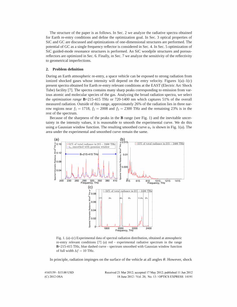
During an Earth atmospheric re-entry, a space vehicle can be exposed to strong radiation fromionized shocked gases whose intensity will depend on the entry velocity. Figures 1(a)–1(c)present spectra obtained for Earth re-entry relevant conditions at the EAST (Electric Arc ShockTube) facility [7]. The spectra contains many sharp peaks corresponding to emission from var-ious atomic and molecular species of the gas. Analyzing the broad radiation spectra, we selectthe optimization range B=215-415 THz or 720-1400 nm which captures 51% of the overallmeasured radiation. Outside of this range, approximately 26% of the radiation lies in three nar-row regions near f1 = 1718, f2 = 2008 and f3 = 2300 THz and the remaining 23% is in therest of the spectrum.
Because of the sharpness of the peaks in the B range (see Fig. 1) and the inevitable uncer-tainty in the intensity values, it is reasonable to smooth the experimental curve. We do thisusing a Gaussian window function. The resulting smoothed curve uν is shown in Fig. 1(a). Thearea under the experimental and smoothed curve remain the same.
Fig. 1. (a)–(c) Experimental data of spectral radiation distribution, obtained at atmosphericre-entry relevant conditions [7] (a) red - experimental radiative spectrum in the rangeB=215-415 THz, blue dashed curve - spectrum smoothed with Gaussian window functionof full width Δ f = 10 THz.
In principle, radiation impinges on the surface of the vehicle at all angles θ . However, shock
#165159 - $15.00 USD Received 21 Mar 2012; accepted 17 May 2012; published 11 Jun 2012(C) 2012 OSA 18 June 2012 / Vol. 20, No. 13 / OPTICS EXPRESS 14191
gases not only emit radiation, but also absorb it. Therefore, the radiation intensity uν thatreaches the surface should be sharply peaked around normal incidence [8]. Because of this,we consider only normally incident light, with the smoothed radiation spectra uν , shown inFig. 1(a).
The goal is to design a radiation shield that maximizes the total reflection of normally inci-dent unpolarized radiation uν . Therefore, the function to be maximized is:
〈Ruν 〉=∫
RΣuν dνutot
, utot =∫
uν dν , (1)
where integration is performed over the B range, RΣ is the total reflection of the incident unpo-larized radiation:
RΣ = 0.5(Rs +Rp), (2)
where Rs and Rp are the sum of reflection efficiencies for the s- and p-polarization, respectively:
Rs,p = Rs,p0 +∑Ds,p
i , i =±1,±2, . . . (3)
here the summation is performed over the propagating diffraction orders in the upper air halfspace. Hereafter, we will refer to 〈Ruν 〉 as the “reflection”. For uniform radiation uν = 1, theEq. (1) reads:
〈R〉=∫
RΣdνΔν
. (4)
For calculations of the structures, considered in Sec. 3-5 we used the scattering matrix ap-proach [9, 10]. CST Studio (Frequency Domain Solver) was used for calculations of the inverseopal structure, considered in Sec. 4 and of structures, considered in Sec. 6. For numerical op-timization, we used evolutionary strategy (ES) algorithms. Based on previous experience [11],ES is very powerful for real parameter optimization problems and outperforms genetic algo-rithm, particle swarm optimization, and other methods in most cases. We used an (m+n) ESwith adaptive mutation for the optimization in the following example. Here m is the initialnumber of parents and n is the number of children created in each generation. In the followingcalculations, m = 6 and n = 7m were used.
3. One-dimensional silicon carbide and glassy carbon structures
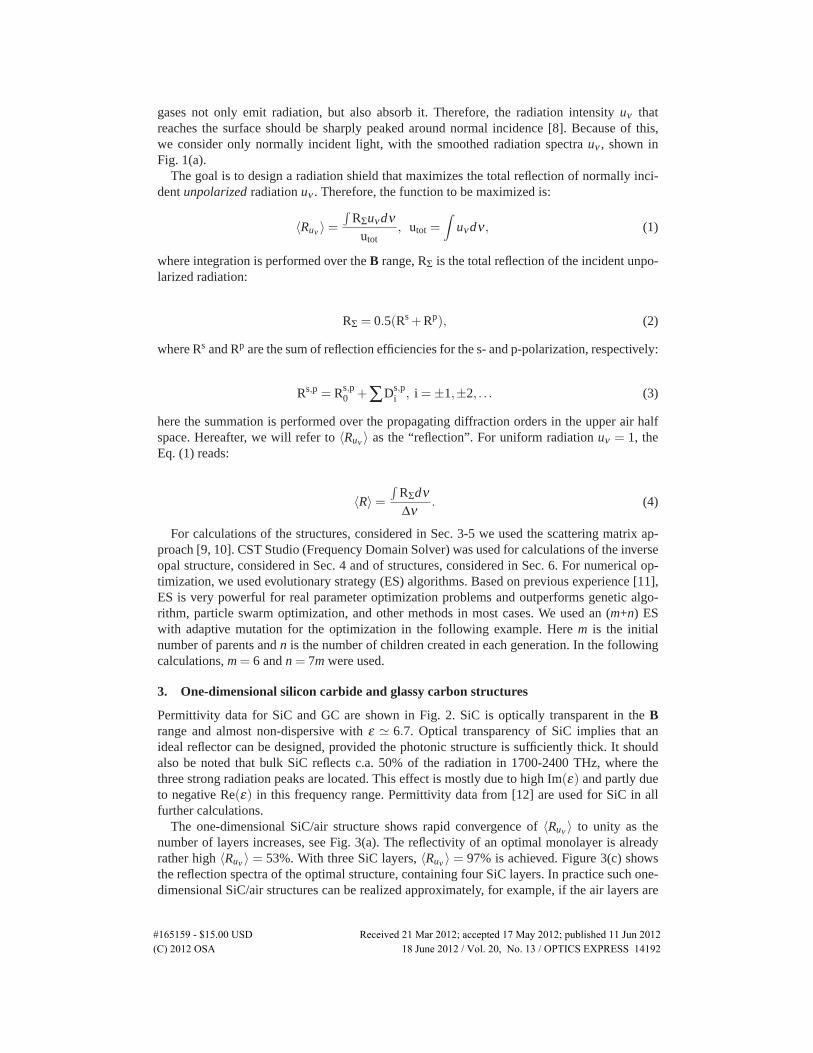
Permittivity data for SiC and GC are shown in Fig. 2. SiC is optically transparent in the Brange and almost non-dispersive with ε � 6.7. Optical transparency of SiC implies that anideal reflector can be designed, provided the photonic structure is sufficiently thick. It shouldalso be noted that bulk SiC reflects c.a. 50% of the radiation in 1700-2400 THz, where thethree strong radiation peaks are located. This effect is mostly due to high Im(ε) and partly dueto negative Re(ε) in this frequency range. Permittivity data from [12] are used for SiC in allfurther calculations.
The one-dimensional SiC/air structure shows rapid convergence of 〈Ruν 〉 to unity as thenumber of layers increases, see Fig. 3(a). The reflectivity of an optimal monolayer is alreadyrather high 〈Ruν 〉 = 53%. With three SiC layers, 〈Ruν 〉 = 97% is achieved. Figure 3(c) showsthe reflection spectra of the optimal structure, containing four SiC layers. In practice such one-dimensional SiC/air structures can be realized approximately, for example, if the air layers are
#165159 - $15.00 USD Received 21 Mar 2012; accepted 17 May 2012; published 11 Jun 2012(C) 2012 OSA 18 June 2012 / Vol. 20, No. 13 / OPTICS EXPRESS 14192
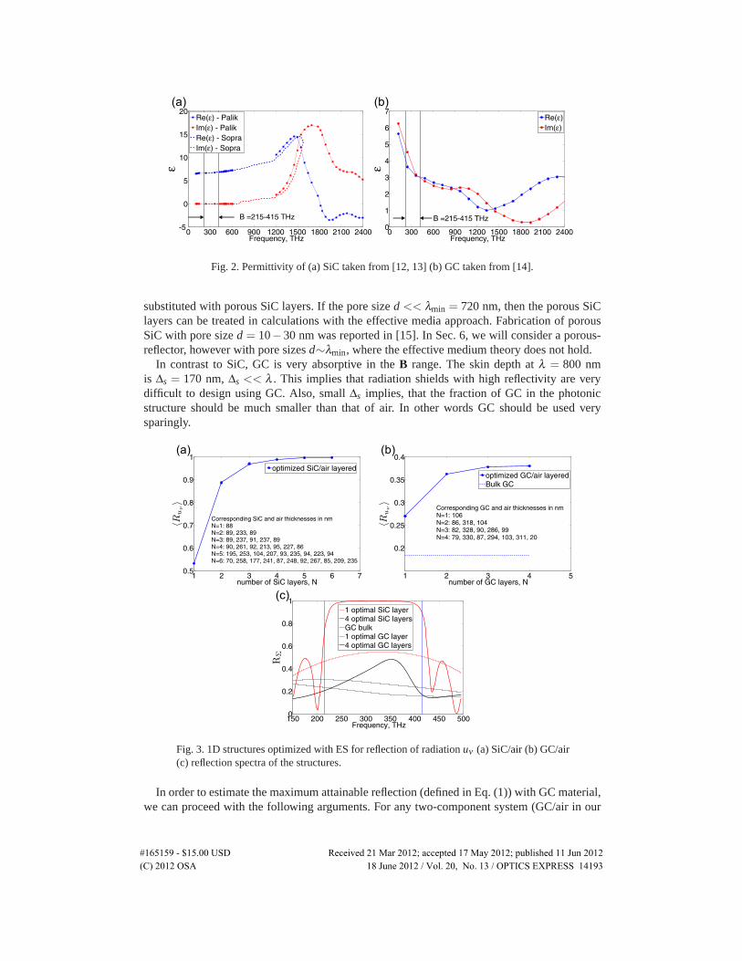
Fig. 2. Permittivity of (a) SiC taken from [12, 13] (b) GC taken from [14].
substituted with porous SiC layers. If the pore size d << λmin = 720 nm, then the porous SiClayers can be treated in calculations with the effective media approach. Fabrication of porousSiC with pore size d = 10−30 nm was reported in [15]. In Sec. 6, we will consider a porous-reflector, however with pore sizes d∼λmin, where the effective medium theory does not hold.
In contrast to SiC, GC is very absorptive in the B range. The skin depth at λ = 800 nmis Δs = 170 nm, Δs << λ . This implies that radiation shields with high reflectivity are verydifficult to design using GC. Also, small Δs implies, that the fraction of GC in the photonicstructure should be much smaller than that of air. In other words GC should be used verysparingly.
Fig. 3. 1D structures optimized with ES for reflection of radiation uν (a) SiC/air (b) GC/air(c) reflection spectra of the structures.
In order to estimate the maximum attainable reflection (defined in Eq. (1)) with GC material,we can proceed with the following arguments. For any two-component system (GC/air in our
#165159 - $15.00 USD Received 21 Mar 2012; accepted 17 May 2012; published 11 Jun 2012(C) 2012 OSA 18 June 2012 / Vol. 20, No. 13 / OPTICS EXPRESS 14193
case) the structure, which has the widest photonic band gap for the chosen direction of the wavevector�k is 1D-periodic [16]. Therefore, among all possible photonic structures, a 1D GC/airstructure should maximize the reflection of normally incident light for both a single frequencyor a frequency range B. The dependence of 〈Ruν 〉, as a function of the number of GC layersis shown in Fig. 3(b). As can be seen, already with two layers almost the maximum reflectionwith the value 〈Ruν 〉 � 38% is reached. While still relatively low, this value is more than 2Xthe bulk value of 18%. Figure 3(c) shows the reflection spectra of the optimal GC/air structure,containing four GC layers.
4. Glassy carbon structures as single frequency reflectors
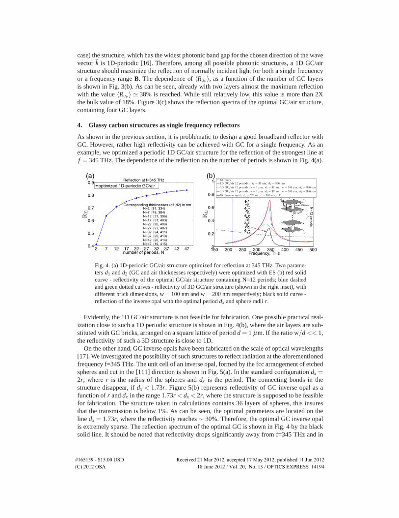
As shown in the previous section, it is problematic to design a good broadband reflector withGC. However, rather high reflectivity can be achieved with GC for a single frequency. As anexample, we optimized a periodic 1D GC/air structure for the reflection of the strongest line atf = 345 THz. The dependence of the reflection on the number of periods is shown in Fig. 4(a).
Fig. 4. (a) 1D-periodic GC/air structure optimized for reflection at 345 THz. Two parame-ters d1 and d2 (GC and air thicknesses respectively) were optimized with ES (b) red solidcurve - reflectivity of the optimal GC/air structure containing N=12 periods; blue dashedand green dotted curves - reflectivity of 3D GC/air structure (shown in the right inset), withdifferent brick dimensions, w = 100 nm and w = 200 nm respectively; black solid curve -reflection of the inverse opal with the optimal period dx and sphere radii r.
Evidently, the 1D GC/air structure is not feasible for fabrication. One possible practical real-ization close to such a 1D periodic structure is shown in Fig. 4(b), where the air layers are sub-stituted with GC bricks, arranged on a square lattice of period d = 1 μm. If the ratio w/d << 1,the reflectivity of such a 3D structure is close to 1D.
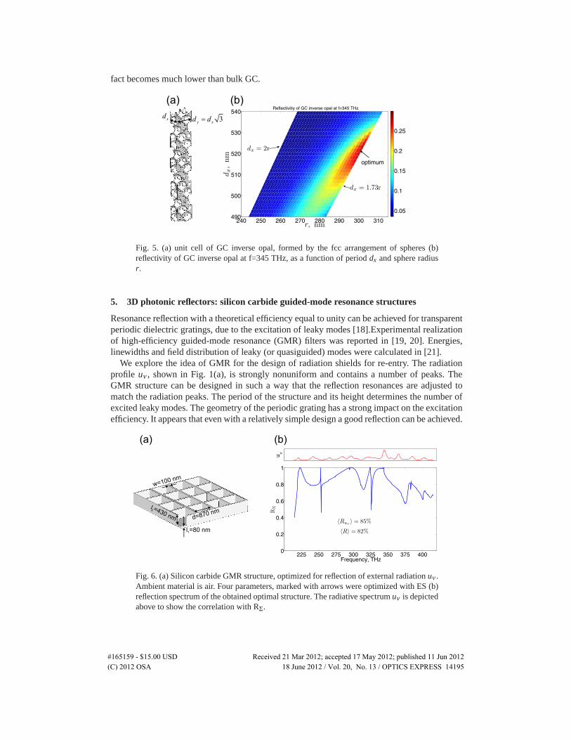
On the other hand, GC inverse opals have been fabricated on the scale of optical wavelengths[17]. We investigated the possibility of such structures to reflect radiation at the aforementionedfrequency f=345 THz. The unit cell of an inverse opal, formed by the fcc arrangement of etchedspheres and cut in the [111] direction is shown in Fig. 5(a). In the standard configuration dx =2r, where r is the radius of the spheres and dx is the period. The connecting bonds in thestructure disappear, if dx < 1.73r. Figure 5(b) represents reflectivity of GC inverse opal as afunction of r and dx in the range 1.73r < dx < 2r, where the structure is supposed to be feasiblefor fabrication. The structure taken in calculations contains 36 layers of spheres, this insuresthat the transmission is below 1%. As can be seen, the optimal parameters are located on theline dx = 1.73r, where the reflectivity reaches ∼ 30%. Therefore, the optimal GC inverse opalis extremely sparse. The reflection spectrum of the optimal GC is shown in Fig. 4 by the blacksolid line. It should be noted that reflectivity drops significantly away from f=345 THz and in
#165159 - $15.00 USD Received 21 Mar 2012; accepted 17 May 2012; published 11 Jun 2012(C) 2012 OSA 18 June 2012 / Vol. 20, No. 13 / OPTICS EXPRESS 14194
fact becomes much lower than bulk GC.
Fig. 5. (a) unit cell of GC inverse opal, formed by the fcc arrangement of spheres (b)reflectivity of GC inverse opal at f=345 THz, as a function of period dx and sphere radiusr.
5. 3D photonic reflectors: silicon carbide guided-mode resonance structures
Resonance reflection with a theoretical efficiency equal to unity can be achieved for transparentperiodic dielectric gratings, due to the excitation of leaky modes [18].Experimental realizationof high-efficiency guided-mode resonance (GMR) filters was reported in [19, 20]. Energies,linewidths and field distribution of leaky (or quasiguided) modes were calculated in [21].
We explore the idea of GMR for the design of radiation shields for re-entry. The radiationprofile uν , shown in Fig. 1(a), is strongly nonuniform and contains a number of peaks. TheGMR structure can be designed in such a way that the reflection resonances are adjusted tomatch the radiation peaks. The period of the structure and its height determines the number ofexcited leaky modes. The geometry of the periodic grating has a strong impact on the excitationefficiency. It appears that even with a relatively simple design a good reflection can be achieved.
Fig. 6. (a) Silicon carbide GMR structure, optimized for reflection of external radiation uν .Ambient material is air. Four parameters, marked with arrows were optimized with ES (b)reflection spectrum of the obtained optimal structure. The radiative spectrum uν is depictedabove to show the correlation with RΣ.
#165159 - $15.00 USD Received 21 Mar 2012; accepted 17 May 2012; published 11 Jun 2012(C) 2012 OSA 18 June 2012 / Vol. 20, No. 13 / OPTICS EXPRESS 14195
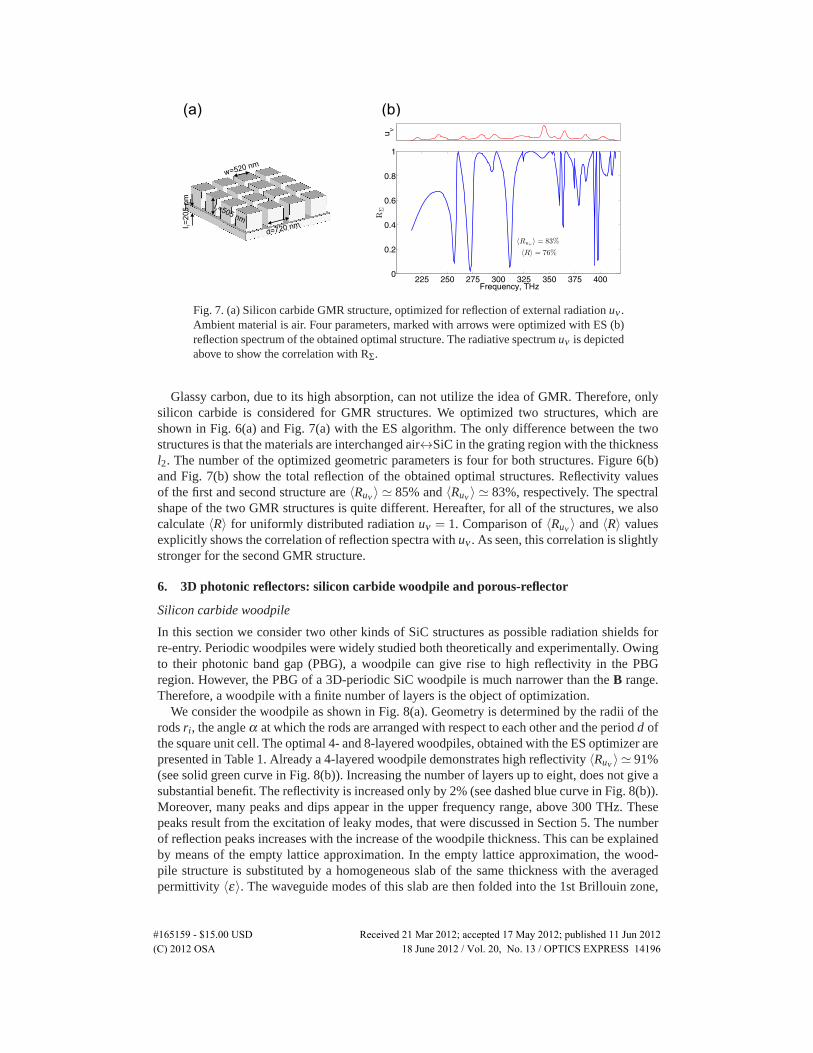
Fig. 7. (a) Silicon carbide GMR structure, optimized for reflection of external radiation uν .Ambient material is air. Four parameters, marked with arrows were optimized with ES (b)reflection spectrum of the obtained optimal structure. The radiative spectrum uν is depictedabove to show the correlation with RΣ.
Glassy carbon, due to its high absorption, can not utilize the idea of GMR. Therefore, onlysilicon carbide is considered for GMR structures. We optimized two structures, which areshown in Fig. 6(a) and Fig. 7(a) with the ES algorithm. The only difference between the twostructures is that the materials are interchanged air↔SiC in the grating region with the thicknessl2. The number of the optimized geometric parameters is four for both structures. Figure 6(b)and Fig. 7(b) show the total reflection of the obtained optimal structures. Reflectivity valuesof the first and second structure are 〈Ruν 〉 � 85% and 〈Ruν 〉 � 83%, respectively. The spectralshape of the two GMR structures is quite different. Hereafter, for all of the structures, we alsocalculate 〈R〉 for uniformly distributed radiation uν = 1. Comparison of 〈Ruν 〉 and 〈R〉 valuesexplicitly shows the correlation of reflection spectra with uν . As seen, this correlation is slightlystronger for the second GMR structure.
6. 3D photonic reflectors: silicon carbide woodpile and porous-reflector
Silicon carbide woodpile
In this section we consider two other kinds of SiC structures as possible radiation shields forre-entry. Periodic woodpiles were widely studied both theoretically and experimentally. Owingto their photonic band gap (PBG), a woodpile can give rise to high reflectivity in the PBGregion. However, the PBG of a 3D-periodic SiC woodpile is much narrower than the B range.Therefore, a woodpile with a finite number of layers is the object of optimization.
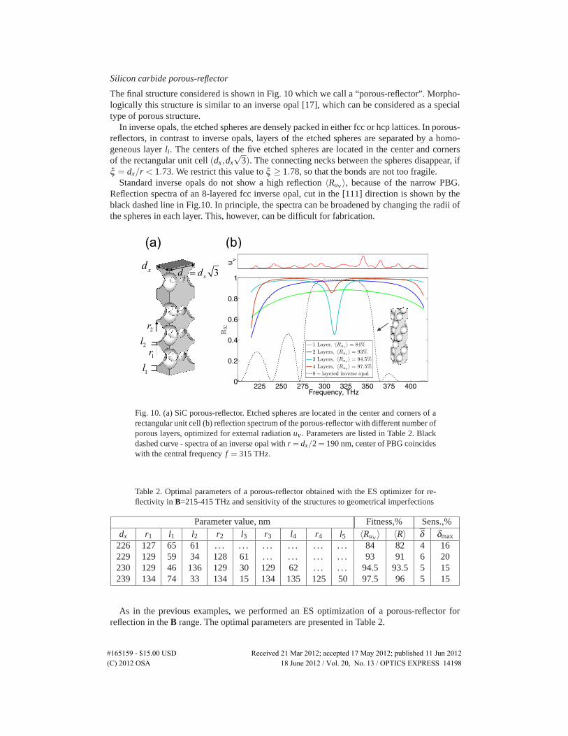
We consider the woodpile as shown in Fig. 8(a). Geometry is determined by the radii of therods ri, the angle α at which the rods are arranged with respect to each other and the period d ofthe square unit cell. The optimal 4- and 8-layered woodpiles, obtained with the ES optimizer arepresented in Table 1. Already a 4-layered woodpile demonstrates high reflectivity 〈Ruν 〉 � 91%(see solid green curve in Fig. 8(b)). Increasing the number of layers up to eight, does not give asubstantial benefit. The reflectivity is increased only by 2% (see dashed blue curve in Fig. 8(b)).Moreover, many peaks and dips appear in the upper frequency range, above 300 THz. Thesepeaks result from the excitation of leaky modes, that were discussed in Section 5. The numberof reflection peaks increases with the increase of the woodpile thickness. This can be explainedby means of the empty lattice approximation. In the empty lattice approximation, the wood-pile structure is substituted by a homogeneous slab of the same thickness with the averagedpermittivity 〈ε〉. The waveguide modes of this slab are then folded into the 1st Brillouin zone,
#165159 - $15.00 USD Received 21 Mar 2012; accepted 17 May 2012; published 11 Jun 2012(C) 2012 OSA 18 June 2012 / Vol. 20, No. 13 / OPTICS EXPRESS 14196
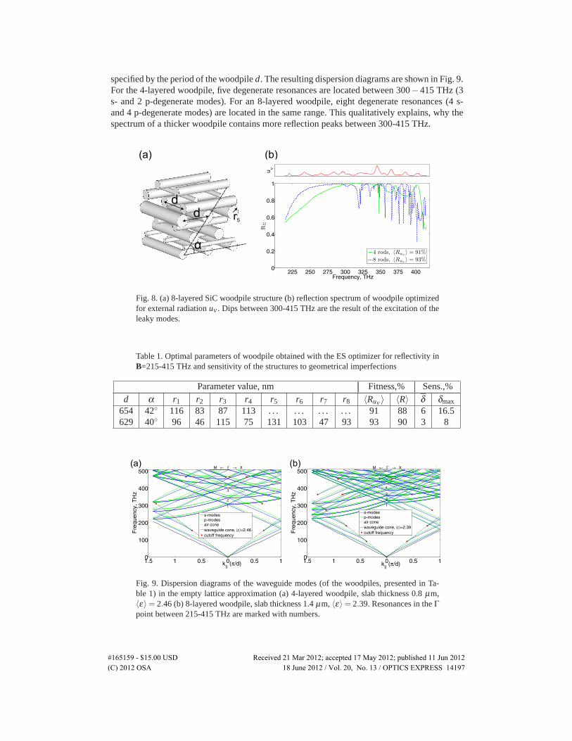
specified by the period of the woodpile d. The resulting dispersion diagrams are shown in Fig. 9.For the 4-layered woodpile, five degenerate resonances are located between 300−415 THz (3s- and 2 p-degenerate modes). For an 8-layered woodpile, eight degenerate resonances (4 s-and 4 p-degenerate modes) are located in the same range. This qualitatively explains, why thespectrum of a thicker woodpile contains more reflection peaks between 300-415 THz.
Fig. 8. (a) 8-layered SiC woodpile structure (b) reflection spectrum of woodpile optimizedfor external radiation uν . Dips between 300-415 THz are the result of the excitation of theleaky modes.
Table 1. Optimal parameters of woodpile obtained with the ES optimizer for reflectivity inB=215-415 THz and sensitivity of the structures to geometrical imperfections
Parameter value, nm Fitness,% Sens.,%d α r1 r2 r3 r4 r5 r6 r7 r8 〈Ruν 〉 〈R〉 δ δmax
654 42◦ 116 83 87 113 . . . . . . . . . . . . 91 88 6 16.5629 40◦ 96 46 115 75 131 103 47 93 93 90 3 8
Fig. 9. Dispersion diagrams of the waveguide modes (of the woodpiles, presented in Ta-ble 1) in the empty lattice approximation (a) 4-layered woodpile, slab thickness 0.8 μm,〈ε〉= 2.46 (b) 8-layered woodpile, slab thickness 1.4 μm, 〈ε〉= 2.39. Resonances in the Γpoint between 215-415 THz are marked with numbers.
#165159 - $15.00 USD Received 21 Mar 2012; accepted 17 May 2012; published 11 Jun 2012(C) 2012 OSA 18 June 2012 / Vol. 20, No. 13 / OPTICS EXPRESS 14197
Silicon carbide porous-reflector
The final structure considered is shown in Fig. 10 which we call a “porous-reflector”. Morpho-logically this structure is similar to an inverse opal [17], which can be considered as a specialtype of porous structure.
In inverse opals, the etched spheres are densely packed in either fcc or hcp lattices. In porous-reflectors, in contrast to inverse opals, layers of the etched spheres are separated by a homo-geneous layer li. The centers of the five etched spheres are located in the center and cornersof the rectangular unit cell (dx,dx
√3). The connecting necks between the spheres disappear, if
ξ = dx/r < 1.73. We restrict this value to ξ ≥ 1.78, so that the bonds are not too fragile.Standard inverse opals do not show a high reflection 〈Ruν 〉, because of the narrow PBG.
Reflection spectra of an 8-layered fcc inverse opal, cut in the [111] direction is shown by theblack dashed line in Fig.10. In principle, the spectra can be broadened by changing the radii ofthe spheres in each layer. This, however, can be difficult for fabrication.
Fig. 10. (a) SiC porous-reflector. Etched spheres are located in the center and corners of arectangular unit cell (b) reflection spectrum of the porous-reflector with different number ofporous layers, optimized for external radiation uν . Parameters are listed in Table 2. Blackdashed curve - spectra of an inverse opal with r = dx/2 = 190 nm, center of PBG coincideswith the central frequency f = 315 THz.
Table 2. Optimal parameters of a porous-reflector obtained with the ES optimizer for re-flectivity in B=215-415 THz and sensitivity of the structures to geometrical imperfections
Parameter value, nm Fitness,% Sens.,%dx r1 l1 l2 r2 l3 r3 l4 r4 l5 〈Ruν 〉 〈R〉 δ δmax
226 127 65 61 . . . . . . . . . . . . . . . . . . 84 82 4 16229 129 59 34 128 61 . . . . . . . . . . . . 93 91 6 20230 129 46 136 129 30 129 62 . . . . . . 94.5 93.5 5 15239 134 74 33 134 15 134 135 125 50 97.5 96 5 15
As in the previous examples, we performed an ES optimization of a porous-reflector forreflection in the B range. The optimal parameters are presented in Table 2.
#165159 - $15.00 USD Received 21 Mar 2012; accepted 17 May 2012; published 11 Jun 2012(C) 2012 OSA 18 June 2012 / Vol. 20, No. 13 / OPTICS EXPRESS 14198
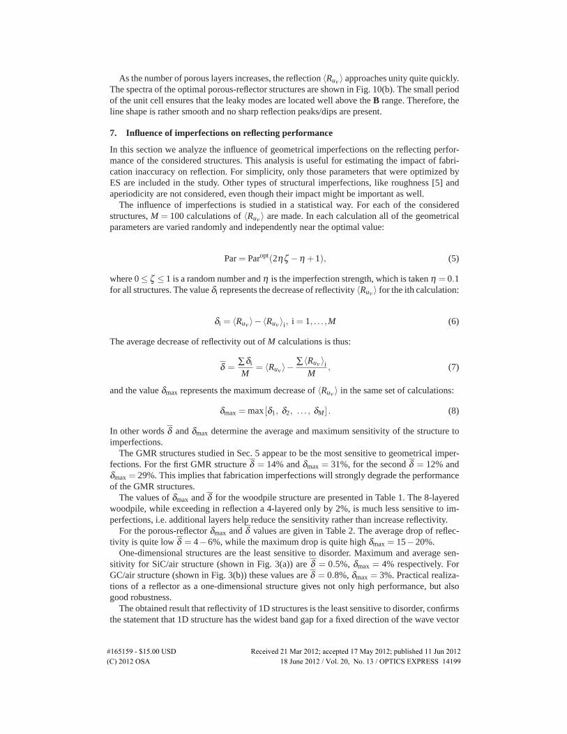
As the number of porous layers increases, the reflection 〈Ruν 〉 approaches unity quite quickly.The spectra of the optimal porous-reflector structures are shown in Fig. 10(b). The small periodof the unit cell ensures that the leaky modes are located well above the B range. Therefore, theline shape is rather smooth and no sharp reflection peaks/dips are present.
7. Influence of imperfections on reflecting performance
In this section we analyze the influence of geometrical imperfections on the reflecting perfor-mance of the considered structures. This analysis is useful for estimating the impact of fabri-cation inaccuracy on reflection. For simplicity, only those parameters that were optimized byES are included in the study. Other types of structural imperfections, like roughness [5] andaperiodicity are not considered, even though their impact might be important as well.
The influence of imperfections is studied in a statistical way. For each of the consideredstructures, M = 100 calculations of 〈Ruν 〉 are made. In each calculation all of the geometricalparameters are varied randomly and independently near the optimal value:
Par = Paropt(2ηζ −η +1), (5)
where 0≤ ζ ≤ 1 is a random number and η is the imperfection strength, which is taken η = 0.1for all structures. The value δi represents the decrease of reflectivity 〈Ruν 〉 for the ith calculation:
δi = 〈Ruν 〉−〈Ruν 〉i, i = 1, . . . ,M (6)
The average decrease of reflectivity out of M calculations is thus:
δ =∑δi
M= 〈Ruν 〉−
∑〈Ruν 〉i
M, (7)
and the value δmax represents the maximum decrease of 〈Ruν 〉 in the same set of calculations:
δmax = max [δ1, δ2, . . . , δM] . (8)
In other words δ and δmax determine the average and maximum sensitivity of the structure toimperfections.
The GMR structures studied in Sec. 5 appear to be the most sensitive to geometrical imper-fections. For the first GMR structure δ = 14% and δmax = 31%, for the second δ = 12% andδmax = 29%. This implies that fabrication imperfections will strongly degrade the performanceof the GMR structures.
The values of δmax and δ for the woodpile structure are presented in Table 1. The 8-layeredwoodpile, while exceeding in reflection a 4-layered only by 2%, is much less sensitive to im-perfections, i.e. additional layers help reduce the sensitivity rather than increase reflectivity.
For the porous-reflector δmax and δ values are given in Table 2. The average drop of reflec-tivity is quite low δ = 4−6%, while the maximum drop is quite high δmax = 15−20%.
One-dimensional structures are the least sensitive to disorder. Maximum and average sen-sitivity for SiC/air structure (shown in Fig. 3(a)) are δ = 0.5%, δmax = 4% respectively. ForGC/air structure (shown in Fig. 3(b)) these values are δ = 0.8%, δmax = 3%. Practical realiza-tions of a reflector as a one-dimensional structure gives not only high performance, but alsogood robustness.
The obtained result that reflectivity of 1D structures is the least sensitive to disorder, confirmsthe statement that 1D structure has the widest band gap for a fixed direction of the wave vector
#165159 - $15.00 USD Received 21 Mar 2012; accepted 17 May 2012; published 11 Jun 2012(C) 2012 OSA 18 June 2012 / Vol. 20, No. 13 / OPTICS EXPRESS 14199
�k. In Ref. [22] it was shown that in an imperfect photonic crystal of thickness d, in the gapregion the transmission is proportional to:
T ∼ exp(−4Δ/Sd(1−βδV2)), (9)
where S is the speed of light in the appropriate band, Δ is the gap value, β ∼ 1 is a numericalparameter, and δV is the average deviation of the specific volume from the ideal structure.Therefore, among the structures with the same fixed disorder δV , the ones with larger Δ willtransmit less light, or accordingly reflect more.
8. Conclusion
Different types of photonic structures composed of glassy carbon and silicon carbide were an-alyzed, as potential radiation shields for atmospheric re-entry. S-matrix and CST Studio (Fre-quency Domain Solver) were used as field solvers and evolutionary strategy was used as anoptimizer. Structures were optimized for the near-infrared part of the radiative spectra profile.Reflectivity of GC structures, in contrast to SiC, are significantly limited, due to material ab-sorption.
Silicon carbide, being optically transparent in the near-infrared, allows us to design highlyreflecting structures in a number of different ways. We optimized one-dimensional structures,woodpiles, guided-mode resonance structures and porous-reflectors.
Sensitivity analysis of the obtained optimal structures was performed, in order to estimatethe role of fabrication tolerances on reflectivity.
GMR structures are expected to be the most sensitive to fabrication inaccuracies. Woodpilesand porous reflector are much less sensitive. One-dimensional structures are expected to bethe most robust to geometrical imperfections and therefore, are of greatest interest for re-entryapplications.
Acknowledgments
The authors are grateful to the colleagues from NASA Ames Research Center, namely to BrettCruden and Dinesh Prabhu for discussions and to Aaron Brandis for providing the experimentaldata of radiative spectra, obtained in the NASA Ames Research Center’s EAST facility. Thiswork was supported by ETH project 0-20590-09, Materials for Infra Red Protection.
#165159 - $15.00 USD Received 21 Mar 2012; accepted 17 May 2012; published 11 Jun 2012(C) 2012 OSA 18 June 2012 / Vol. 20, No. 13 / OPTICS EXPRESS 14200