Embed Size (px)
Citation preview
Potential applications of category theory to design: Example of brakes
Eswaran Subrahmanian (CMU/NIST)AMS Sectional Meeting: Session on
Applied Category theoryNovember 9-10, 2019
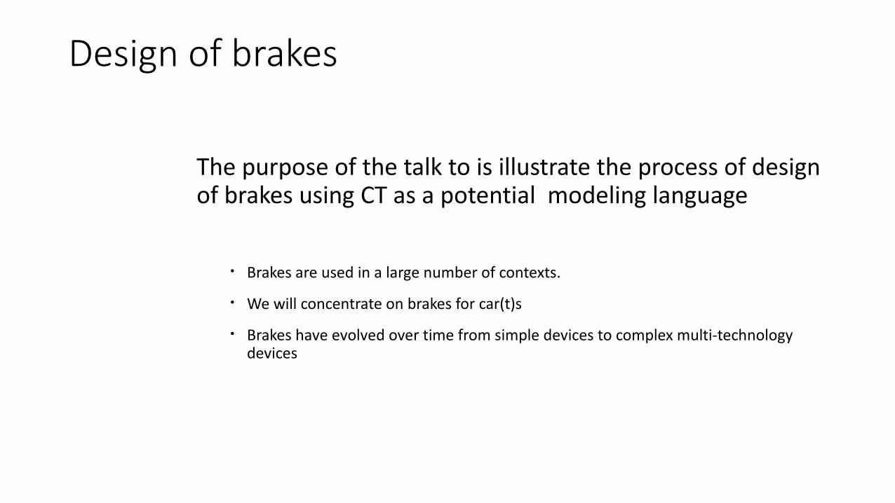
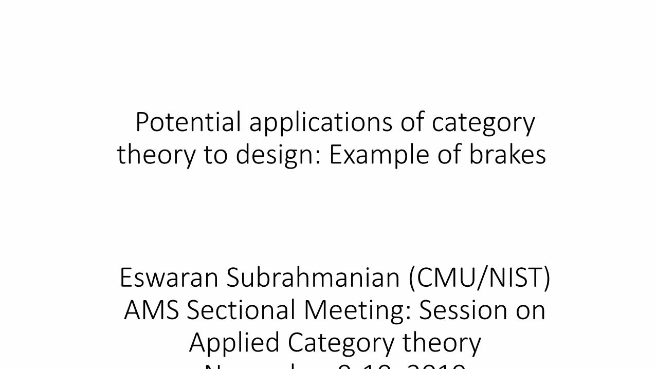
Design of brakes
The purpose of the talk to is illustrate the process of design of brakes using CT as a potential modeling language
• Brakes are used in a large number of contexts.
• We will concentrate on brakes for car(t)s
• Brakes have evolved over time from simple devices to complex multi-technology devices
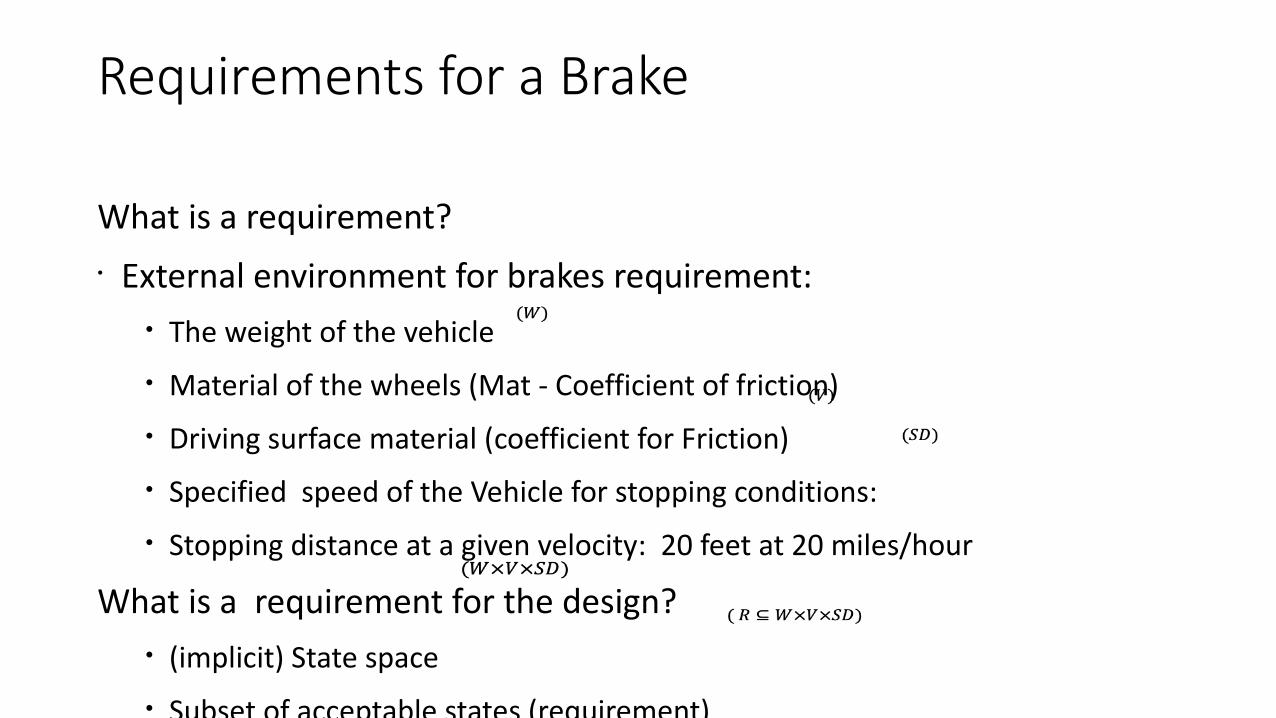
Requirements for a Brake
What is a requirement?• External environment for brakes requirement:
• The weight of the vehicle
• Material of the wheels (Mat - Coefficient of friction)
• Driving surface material (coefficient for Friction)
• Specified speed of the Vehicle for stopping conditions:
• Stopping distance at a given velocity: 20 feet at 20 miles/hour
What is a requirement for the design?• (implicit) State space
• Subset of acceptable states (requirement)
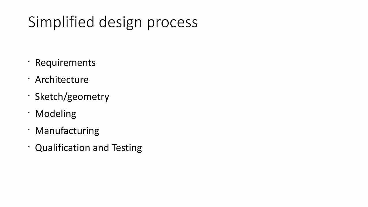
Simplified design process
• Requirements• Architecture• Sketch/geometry• Modeling• Manufacturing• Qualification and Testing
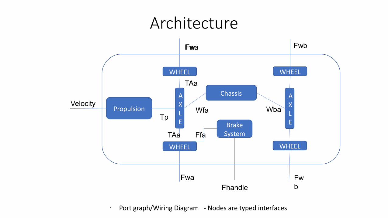
Architecture
WHEEL
WHEEL
WHEEL
WHEEL
Propulsion
AXLE
AXLE
Chassis
BrakeSystem
Fhandle
TpWfa Wba
TAa
TAa Ffa
Fwa
Fwa
FwbFw
Fwb
Velocity
• Port graph/Wiring Diagram - Nodes are typed interfaces
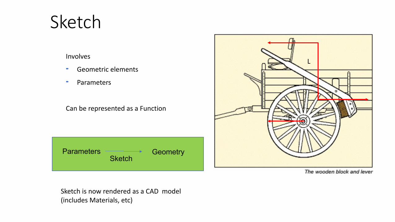
Sketch
Involves Geometric elements Parameters
Can be represented as a Function
Parameters GeometrySketch
Sketch is now rendered as a CAD model (includes Materials, etc)
L
R

Idealization• Simplification
• Negligible lateral load transfer
• Negligible longitudinal load transfer
• Negligible significant roll and pitch motion
• ……….
• Parameters• Radius of the wheel rw
• Velocity (V)= 20 mph• Power Pd= 5Hp
• Free body diagrams (forces)
mg
Pd, v
rw
Fdf RrFdrRf FBf
FhumanL2
L1
Geometry PhysicsIdealize
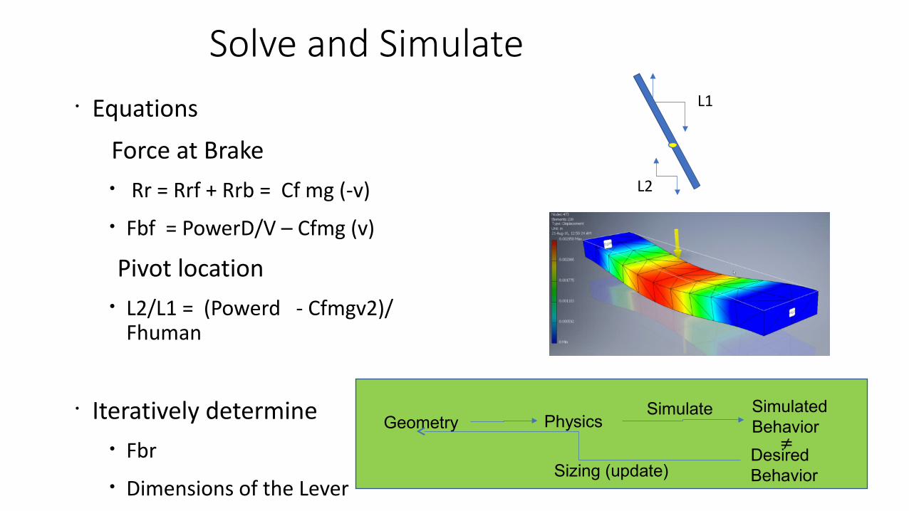
Solve and Simulate• Equations
Force at Brake• Rr = Rrf + Rrb = Cf mg (-v)
• Fbf = PowerD/V – Cfmg (v)
Pivot location• L2/L1 = (Powerd - Cfmgv2)/
Fhuman
• Iteratively determine• Fbr
• Dimensions of the Lever
Sizing of the Lever dimensions for wood -(shape and measurements)
• Stress analysis (FEM)
L1
L2
PhysicsSimulatedBehavior
SimulateGeometry
Sizing (update)
Desired Behavior
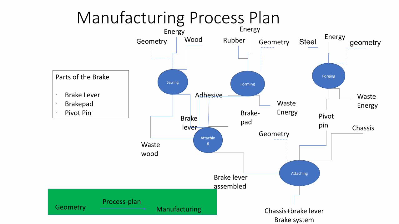
Manufacturing Process PlanWood
Sawing
Brake lever
Rubber
Forming
Geometry Geometry Steel
Forging
geometry
Brake-pad
Attaching
Brake leverassembled
Pivotpin
Attaching
Chassis
Chassis+brake leverBrake system
Geometry Manufacturing
Geometry
Adhesive
Process-plan
Wastewood
Energy
WasteEnergy
Parts of the Brake
• Brake Lever• Brakepad• Pivot Pin
Energy Energy
WasteEnergy
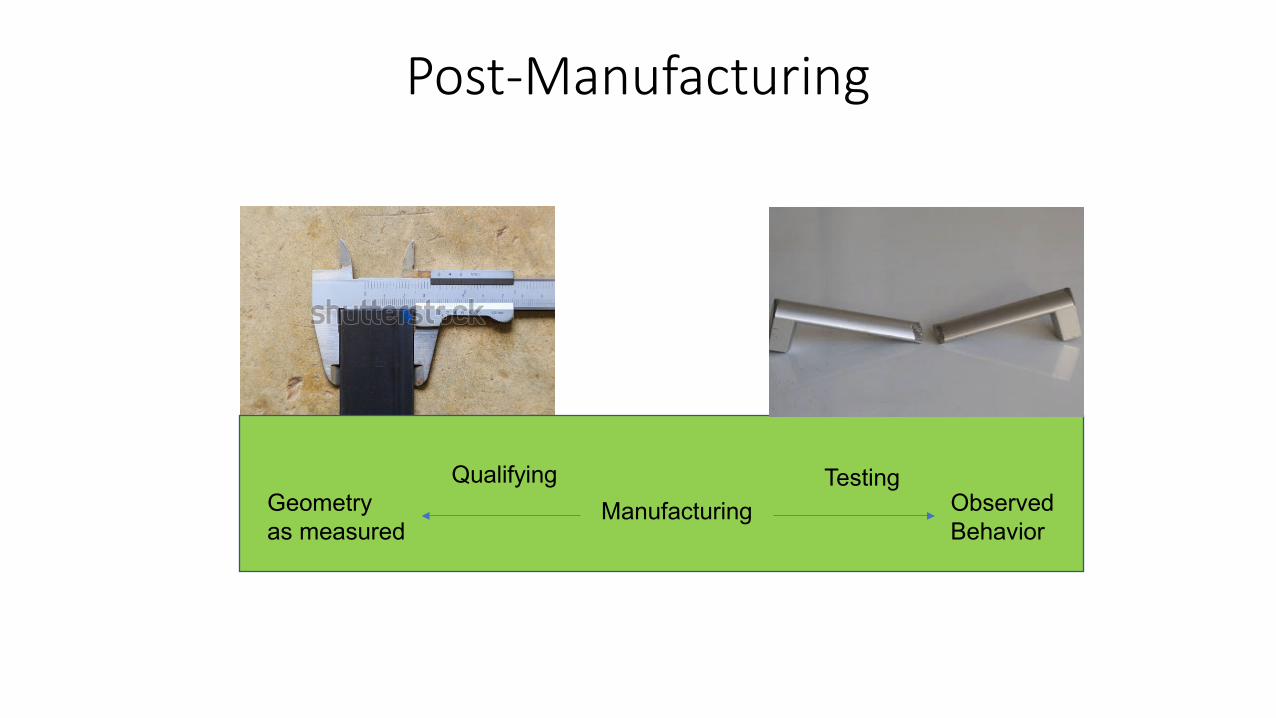
Post-Manufacturing
Manufacturing
QualifyingGeometryas measured
ObservedBehavior
Testing
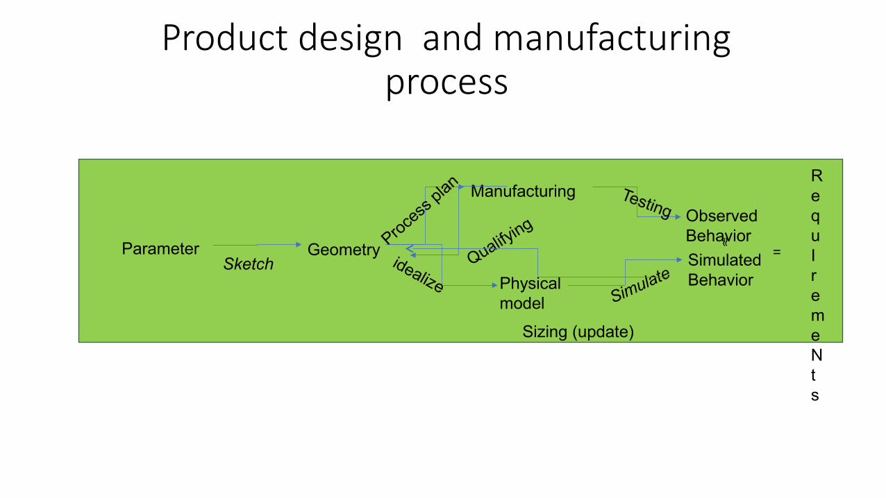
Product design and manufacturing process
ParameterSketch
Geometry
Physical model
Manufacturing
SimulatedBehavior
Testing
Simulate
idealize
Proce
ss pl
an
Qualifying
RequIremeNts
ObservedBehavior
Sizing (update)
=

Design Feedback Loops
Physics based models do not meet requirements
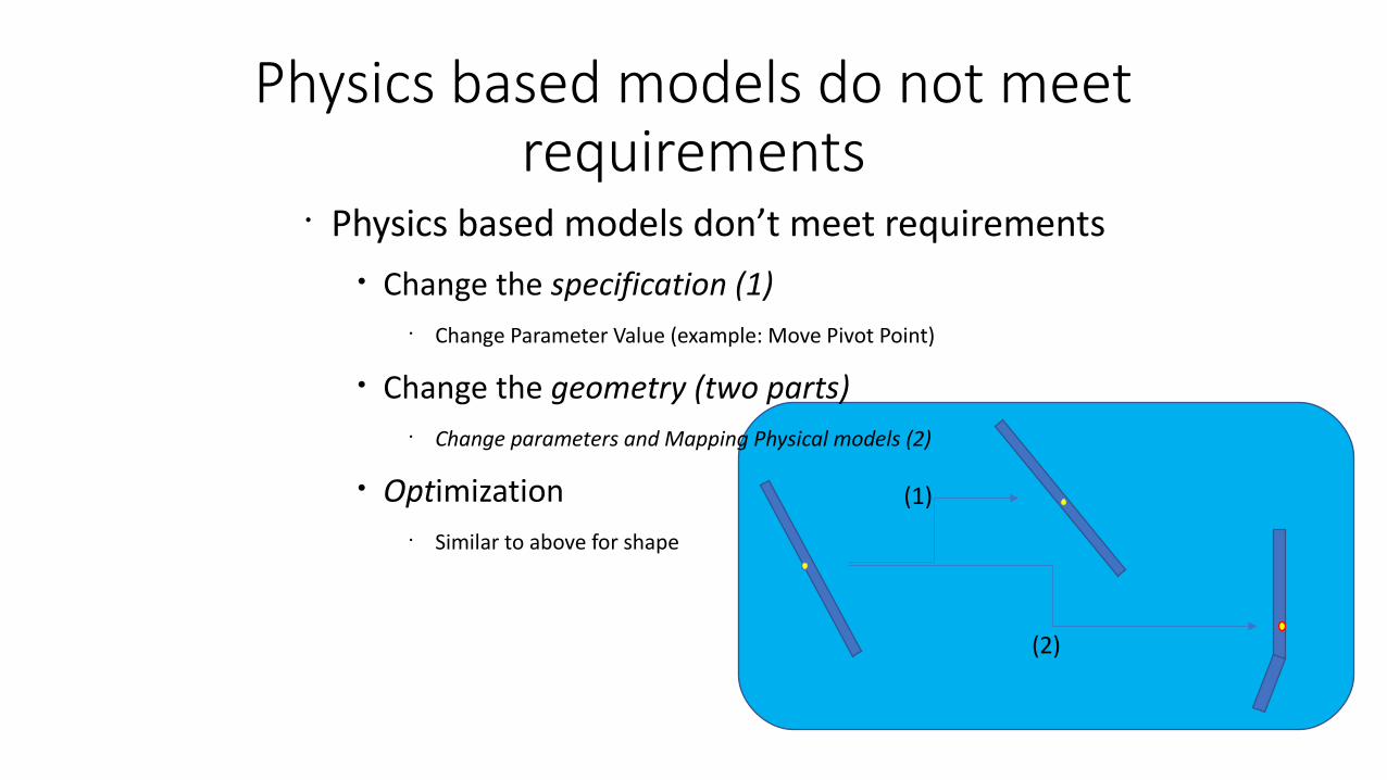
• Physics based models don’t meet requirements• Change the specification (1)
• Change Parameter Value (example: Move Pivot Point)
• Change the geometry (two parts) • Change parameters and Mapping Physical models (2)
• Optimization• Similar to above for shape
(2)
(1)

Changed geometry Change manufacturing
• Changed part geometry• Change process plan
Wood
Sawing
Part 2Geometry
Wood
Sawing
Part 1Geometry
Part 2
Attach
Part 1
Fastners
Brake LeverAssembled

Physics model and testing diverge• Physics model and testing diverge
• Tune parameters (change in the Simulation)
• More complex model (change “Idealize”)
• Modify Requirements
Geometry
Physical model
SimulatedBehavior
Simulate
idealize
Manufacturing TestingProce
ss
plan ObservedBehavior
RequirEment

Product Evolution(change in requirement and architecture)
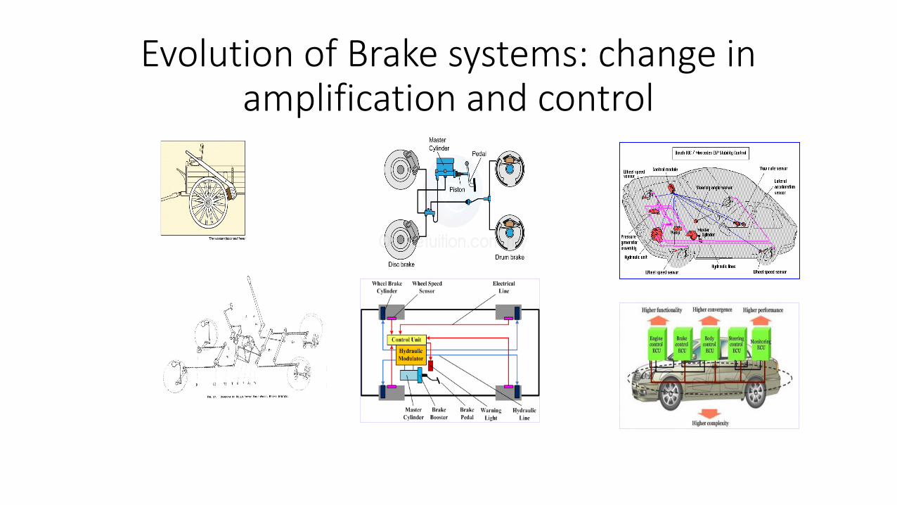
Evolution of Brake systems: change in amplification and control
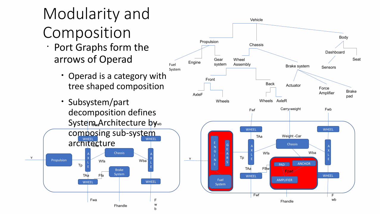
Modularity and Composition
• Port Graphs form the arrows of Operad
• Operad is a category with tree shaped composition
• Subsystem/part decomposition defines System Architecture by composing sub-system architecture
Vehicle
Chassis
Body
SeatWheelAssembly
AxleF
Wheels
FrontBack
AxleR
Propulsion
EngineGearsystem
Wheels
Brake system
ActuatorForceAmplifier Brake
pad
Dashboard
Sensors
WHEEL
WHEEL
WHEEL
WHEEL
AXLE
AXLE
Chassis
Fhandle
TpWfa Wba
TAa
TAa FBw
Fwb
Fwf
Fwf
Fwb
ENGINE
GEARS
Weight -Car
PAD
AMPLIFIER
Fpad
ANCHOR v
Carry-weight
WHEEL
WHEEL
WHEEL
WHEEL
Propulsion
AXLE
AXLE
Chassis
BrakeSystem
Fhandle
TpWfa Wba
TAa
TAa Ffa
Fwa
Fwa
FwbFw
Fwb
v
FuelSystem
FuelSystem
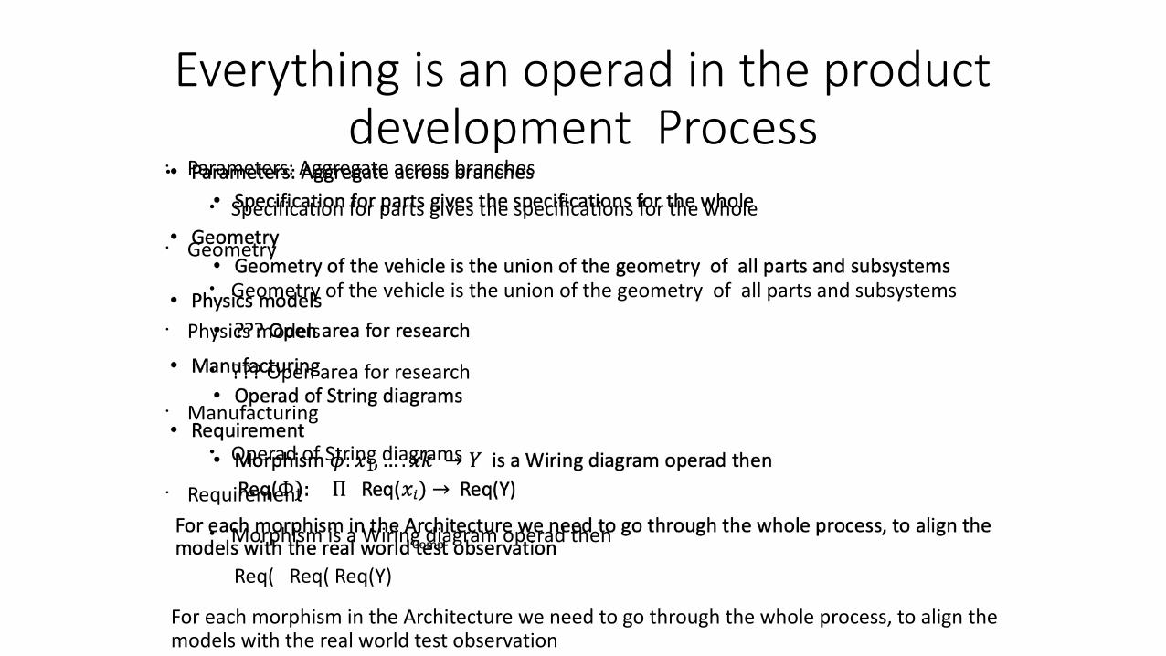
Everything is an operad in the product development Process
• Parameters: Aggregate across branches
• Specification for parts gives the specifications for the whole
• Geometry
• Geometry of the vehicle is the union of the geometry of all parts and subsystems
• Physics models
• ??? Open area for research
• Manufacturing
• Operad of String diagrams
• Requirement
• Morphism is a Wiring diagram operad then
Req( Req( Req(Y)
For each morphism in the Architecture we need to go through the whole process, to align the models with the real world test observation
•
Comp
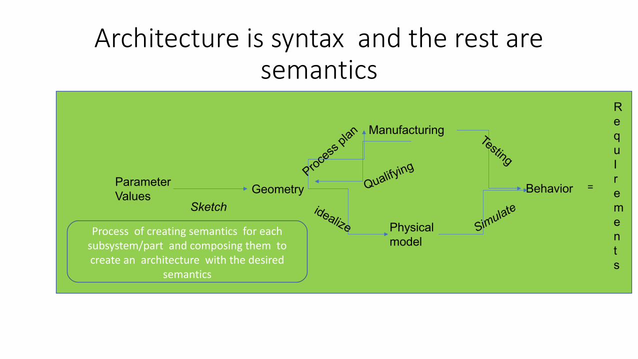
Architecture is syntax and the rest are semantics
ParameterValues
Sketch
Geometry
Physical model
Manufacturing
Behavior
Testing
Simulateidealize
Proce
ss plan
Qualifying
RequIrements
Process of creating semantics for each subsystem/part and composing them tocreate an architecture with the desired
semantics
=

References and Future work
String diagrams for process planning• Spencer Briener, Albert Jones and Eswaran Subrahmanian,
Categorical models for process planning, Computers and Industry, November, 2019.
Operads for architecture description and diagnosis• Spencer Breiner, Olivier Marie-Rose, Blake S. Pollard, and
Eswaran Subrahmanian, Operadic diagnosis in hierarchical systems, ACT Oxford
Future work
Relation of Lenses to design representation update problem
Thank you
This work is done with Spencer Breiner and Blake Pollard at NIST.