Embed Size (px)
Citation preview
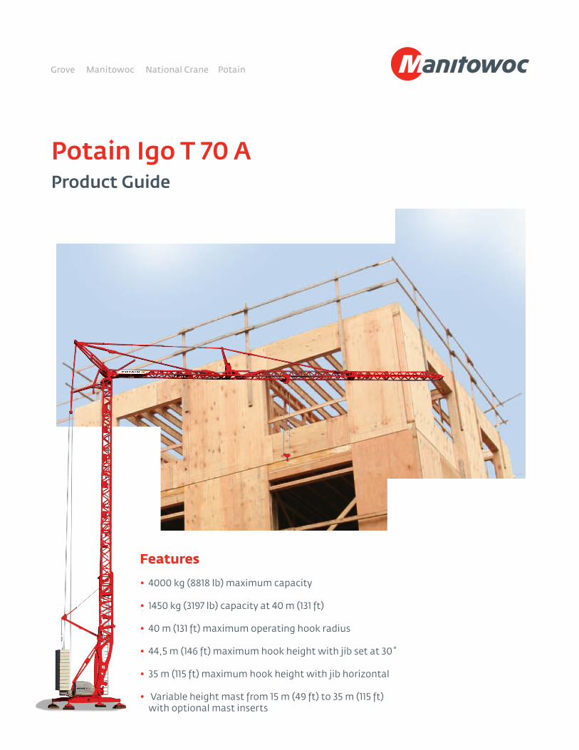
Potain Igo T 70 AProduct Guide
Features • 4000 kg (8818 lb) maximum capacity
• 1450 kg (3197 lb) capacity at 40 m (131 ft)
• 40 m (131 ft) maximum operating hook radius
• 44,5 m (146 ft) maximum hook height with jib set at 30˚
• 35 m (115 ft) maximum hook height with jib horizontal
• Variable height mast from 15 m (49 ft) to 35 m (115 ft) with optional mast inserts
Features
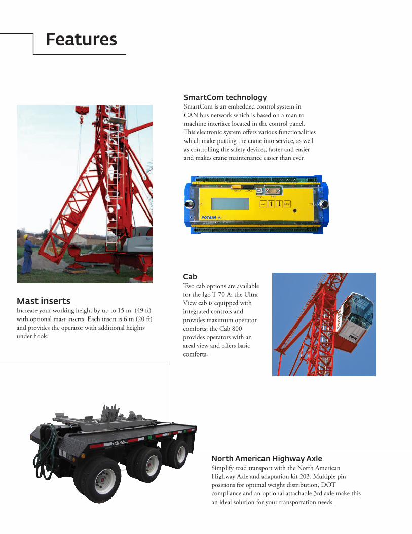
North American Highway AxleSimplify road transport with the North American Highway Axle and adaptation kit 203. Multiple pin positions for optimal weight distribution, DOT compliance and an optional attachable 3rd axle make this an ideal solution for your transportation needs.
SmartCom technologySmartCom is an embedded control system in CAN bus network which is based on a man to machine interface located in the control panel. This electronic system offers various functionalities which make putting the crane into service, as well as controlling the safety devices, faster and easier and makes crane maintenance easier than ever.
Mast insertsIncrease your working height by up to 15 m (49 ft) with optional mast inserts. Each insert is 6 m (20 ft) and provides the operator with additional heights under hook.
CabTwo cab options are available for the Igo T 70 A: the Ultra View cab is equipped with integrated controls and provides maximum operator comforts; the Cab 800 provides operators with an areal view and offers basic comforts.
Contents
Features 2
Specifications 4
Transport 5
Weights 6
Dimensions 7
Crane profile & working range 8
Load charts 9
Mechanisms 10
Metric dimensions 11
Metric crane profile 12
Metric load charts 13
Metric mechanisms 14
Symbols glossary 15

4
Specifications
*Denotes optional equipment
Jib
40 m (131 ft) radius standard offsettable lattice jib. Jib can be offset to 30˚. Opening and aligning are carried out automatically by three hydraulic cylinders.
Telescoping lattice mast is made vertical by one hydraulic cylinder. Hook heights of 15 m (49 ft), 17 m (56 ft), and 20 m (66 ft) achievable with standard mast. 360˚ rotation possible during raising sequence.
Outriggers swing and lock into position. 4,5 m (14.8 ft) square outrigger spread with 2,7 m (8.9 ft) slewing radius. Outrigger pads are stowed on the crane during transport (600 mm x 600 mm [23.6 in x 23.6 in]).
Ballast requirement for the crane consists of, at minimum, 15 slabs each weighing 2200 kg (4850 lb). An additional slab is required if cab is mounted as well as another if mast insert(s) is used. Maximum counterweight is permissible in all configurations except when forbidden, please consult the crane’s manual for details.
Removable and able to be used on other Igo T 70 A units, the hydraulic ballasting derrick uses the hoisting winch and is controlled by the remote control.
480 volt, 60 Hz measured at the turntable. Earth rod and electric cable stowed on the crane during transport.
SM/DM block for 2 (SM) or 4-part line (DM). Manual removal of one pin to change between SM and DM. Pure SM1 (section of hook block removed) is possible with gain of 100 kg (220 lb) lifting capacity.
Wireless remote control provides information to the operator about wind speed, radius, hook height, load, and moment. Lights and buzzers alert the operator when nearing limits of operation. Battery charger and extra battery are provided with crane.Auxiliary remote attached by tethered cord ensures continual operation in case of battery or other malfunction of the wireless remote control.
Electronic wind speed meter to alert the operator of wind speed conditions. Provides selective display on the radio remote. Maximum in service wind speed is 72 km/h (45 mph) and maximum out of service wind speed is 150 km/h (93 mph).
RVF 151 Optima +: slewing mechanism with maximum swing speed of 0.8 rpm. Progressive control of speed with counter-slewing possible, anti-load swinging system makes aligning the load with the jib easier. Multiple rpm speeds possible depending upon parameter selected.
15 LVF 11 Optima: 15 hp variable frequency hoist with 1.1 t (1.2 USt) line pull. 3 notch, progressive speed change according to the accelerating or decelerating ramps. Optima allows the hoist to adapt its speed to the weight of the load.
3 DVF 5: 3 hp variable frequency hoist with 500 kg (1102 lb) line pull. Three (3) notch winch, progressive speed change according to acceleration or deceleration ramps controlled by the frequency converter.
Hydraulic cylinders are used for raising the mast, unfolding the jib, and slewing the derrick. All actions are carried about by the remote control.
Axle sets are available for both jobsite and highway applications. Jobsite axles are rated at either 10 km/h (6 mph) or 25 km/h (15.5 mph); highway axle set is rated at 80 km/h (50 mph).
• STANDARDNORTHAMERICANSPECIFICATION: includes offsettable jib, pre-equipment for interference system, three mast inserts, Top Zone and sixteen (16) slabs of counterweight.
• Mastinserts6m(20ft)• Fixedheightcab(UltraVieworCab800)• Accessladders• Transportaxlesandkits• TopZone• TopTracingConsult price list for additional options
Mast
Chassis
*Ballast
*Optional hydraulic ballasting derrick
Electrical requirement
Reeving
Anemometer
Controls
Swing
Hoist
Trolley
Hydraulic equipment
*Optional transport axle sets
*Optional equipment
Three 6 m (20 ft) mast inserts available to reach a maximum hook height of 35 m (115 ft). Increasing mast height with one insert provides hook heights of 23 m (75 ft) and 26 m (85 ft); second mast insert provides hook heights of 29 m (95 ft) and 32 m (105 ft); third mast insert provides hook height of 35 m (115 ft).
*Optional mast inserts
5Potain Igo T 70 A
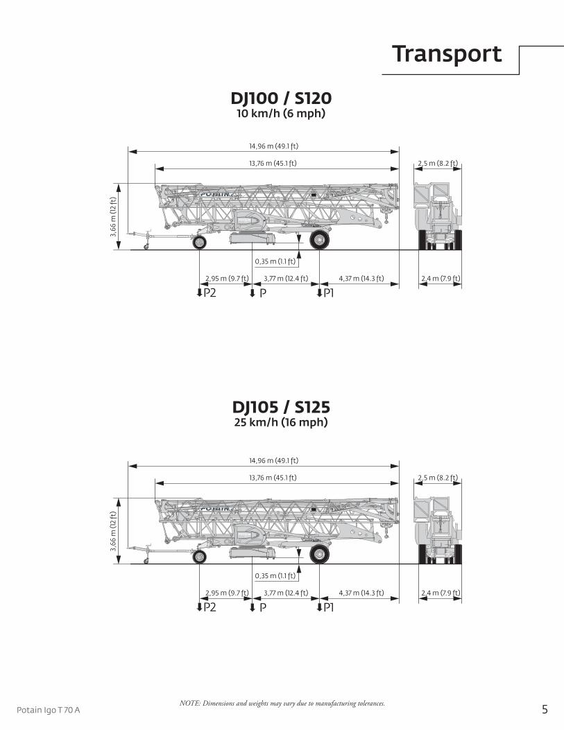
Transport
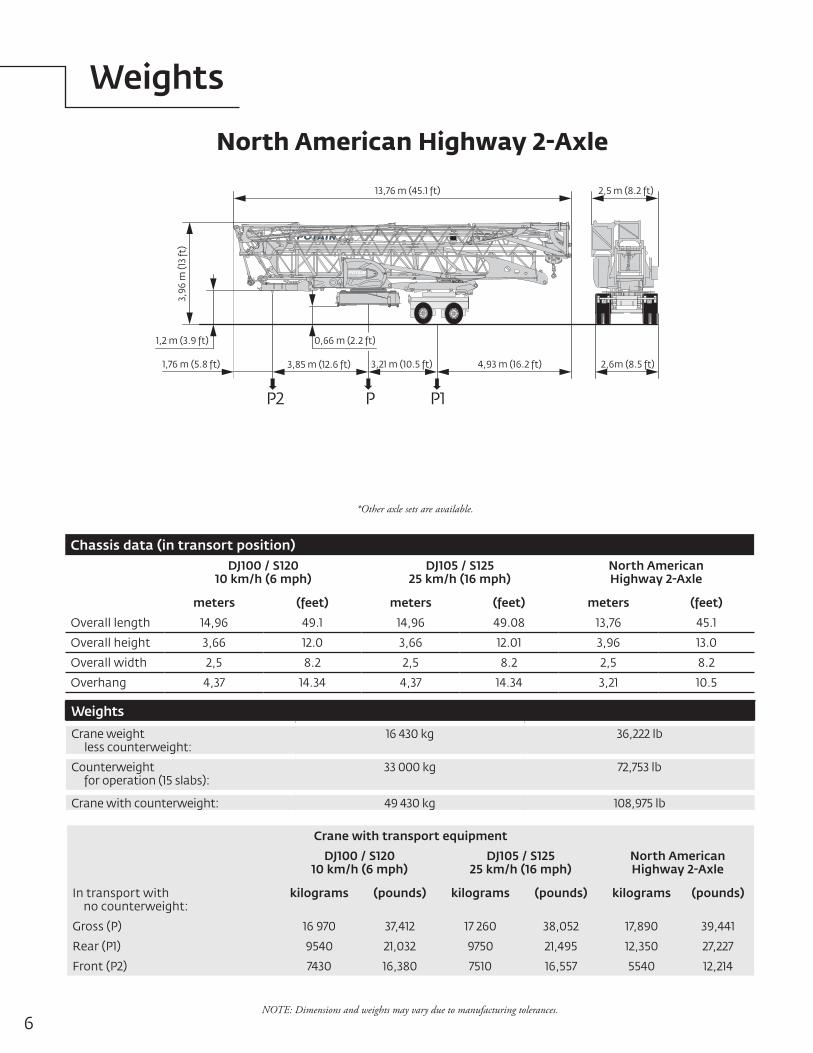
NOTE: Dimensions and weights may vary due to manufacturing tolerances.
DJ105 / S125 25 km/h (16 mph)
DJ100 / S120 10 km/h (6 mph)
14,96 m (49.1 ft)
2,95 m (9.7 ft) 3,77 m (12.4 ft)
3,66
m (1
2 ft
)
4,37 m (14.3 ft)
13,76 m (45.1 ft) 2,5 m (8.2 ft)
2,4 m (7.9 ft)
P1PP2
0,35 m (1.1 ft)
14,96 m (49.1 ft)
2,95 m (9.7 ft) 3,77 m (12.4 ft)
3,66
m (1
2 ft
)
4,37 m (14.3 ft)
13,76 m (45.1 ft) 2,5 m (8.2 ft)
2,4 m (7.9 ft)
P1PP2
0,35 m (1.1 ft)
6
Weights
NOTE: Dimensions and weights may vary due to manufacturing tolerances.
North American Highway 2-Axle
P1PP2
3,85 m (12.6 ft) 3,21 m (10.5 ft)
3,96
m (1
3 ft
)
4,93 m (16.2 ft)
13,76 m (45.1 ft) 2,5 m (8.2 ft)
2,6m (8.5 ft)
1,2 m (3.9 ft)
1,76 m (5.8 ft)
0,66 m (2.2 ft)
*Other axle sets are available.
Chassis data (in transort position)DJ100 / S120
10 km/h (6 mph)DJ105 / S125
25 km/h (16 mph)North American Highway 2-Axle
meters (feet) meters (feet) meters (feet)
Overall length 14,96 49.1 14,96 49.08 13,76 45.1
Overall height 3,66 12.0 3,66 12.01 3,96 13.0
Overall width 2,5 8.2 2,5 8.2 2,5 8.2
Overhang 4,37 14.34 4,37 14.34 3,21 10.5
Weights
Crane weight less counterweight:
16 430 kg 36,222 lb
Counterweight for operation (15 slabs):
33 000 kg 72,753 lb
Crane with counterweight: 49 430 kg 108,975 lb
Crane with transport equipment
DJ100 / S12010 km/h (6 mph)
DJ105 / S12525 km/h (16 mph)
North American Highway 2-Axle
In transport with no counterweight:
kilograms (pounds) kilograms (pounds) kilograms (pounds)
Gross (P) 16 970 37,412 17 260 38,052 17,890 39,441
Rear (P1) 9540 21,032 9750 21,495 12,350 27,227
Front (P2) 7430 16,380 7510 16,557 5540 12,214
7Potain Igo T 70 A
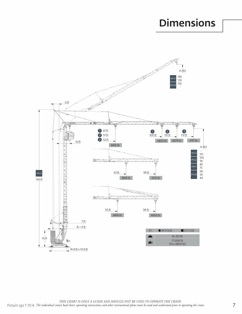
Dimensions
THIS CHART IS ONLY A GUIDE AND SHOULD NOT BE USED TO OPERATE THE CRANE. The individual crane’s load chart, operating instructions and other instructional plates must be read and understood prior to operating the crane.
94 ft
5512 lb
63 ft
8818 lb
94 ft
4850 lb
55 ft
8818 lb
3197 lb
131 ft115 ft100 ft321
4079 lb4850 lb3 52 ft
2 57 ft
1 61 ft
8818 lb
14.8 ft x 14.8 ft
16 ft
H+3
134 ft
R = 9 ft
7 ft
6 ft
10 ft
H (ft)
115-
H+3
95105
H+2
7585
H+1
5666
H+049
H (ft)
H+3136146H+1
-126H+0
F1
F1 34.9 USt 33.7 USt
36,222 lb
77,600 lb (16 x 4850 lb)
8THIS CHART IS ONLY A GUIDE AND SHOULD NOT BE USED TO OPERATE THE CRANE.
The individual crane’s load chart, operating instructions and other instructional plates must be read and understood prior to operating the crane.
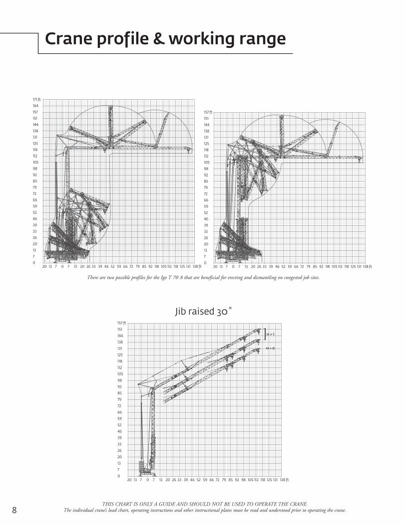
Crane profile & working range
There are two possible profiles for the Igo T 70 A that are beneficial for erecting and dismantling on congested job sites.
20 13 7 0 7 13 20 26 33 39 46 52 59 66 72 79 85 92 98 105 112 118 125 131 138 ft
7
13
20
26
33
39
46
52
59
66
72
79
85
92
98
105
112
118
125
131
138
144
151
157 ft
0
164
171 ft
20 13 7 0 7 13 20 26 33 39 46 52 59 66 72 79 85 92 98 105 112 118 125 131 138 ft
7
13
20
26
33
39
46
52
59
66
72
79
85
92
98
105
112
118
125
131
138
144
151
157
0
20 13 7 0 7 13 20 26 33 39 46 52 59 66 72 79 85 92 98 105 112 118 125 131 138 ft
7
13
20
26
33
39
46
52
59
66
72
79
85
92
98
105
112
118
125
131
138
144
151
157 ft
0
H + 1
H + 0
Jib raised 30˚
9Potain Igo T 70 A
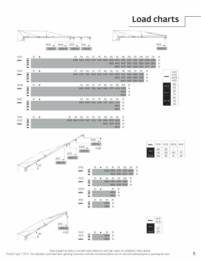
Load charts
THIS CHART IS ONLY A GUIDE AND SHOULD NOT BE USED TO OPERATE THE CRANE. The individual crane’s load chart, operating instructions and other instructional plates must be read and understood prior to operating the crane.
131 ft 115 ft 100 ft 94 ft
H+1146 138 - -136 128 120 117
H+0 126 118 111 107
4850 lb
94 ft
3197 lb
115 ft100 ft 131 ft
4079 lb4850 lb
94 ft
5512 lb
131 ft 10 55 59 66 72 79 85 90 92 94 ft115 ft 8818 8069 7099 6327 5710 5181 4850 4729 4630 lb
4850 4729 4630 lb4850 lb
131 ft 10 52 59 66 72 79 85 86 92 98 105 112 118 125 131 ft8818 7650 6746 5997 5401 4894 4850 4475 4101 3792 3527 3285 3064 2866 lb
4850 4475 4101 3792 3527 3285 3064 2866 lb4850 4519 4189 3858 3638 3417 3197 lb
115 ft 10 57 59 66 72 79 85 92 93 98 105 112 115 ft8818 8378 7385 6592 5930 5379 4916 4850 4531 4189 3880 3748 lb
4850 4531 4189 3880 3748 lb4850 4519 4189 4079 lb
100 ft 10 61 66 72 79 85 92 98 100 ft8818 8047 7165 6460 5886 5379 4938 4850 lb
4850 lb4850 lb
94 ft 10 63 66 72 79 85 92 94 ft8818 8400 7496 6768 6151 5622 5512 lb
4850 lb4850 lb
30°4850 lb
81 ft
87 ft
4850 lb
100 ft
4079 lbH (ft)
114 ft
3197 lb
131 ft 10 75 81 92 102 114 ft4850 4409 3781 3329 2866 lb
4850 4189 3638 3197 lb
115 ft 10 81 87 92 100 ft4850 4453 4145 3748 lb
4850 4519 4079 lb
100 ft 10 87 ft4850 lb4850 lb
94 ft 10 81 ft4850 lb4850 lb
30°
81 ft
4850 lb
H (ft) 131 ft 10 81 ft115 ft 4850 lb
4850 lb
131 ft115 ft
H+1-
117H+0 107
131 ft115 ft100 ft94 ft
H+210595
H + 18575
H + 0665649
10
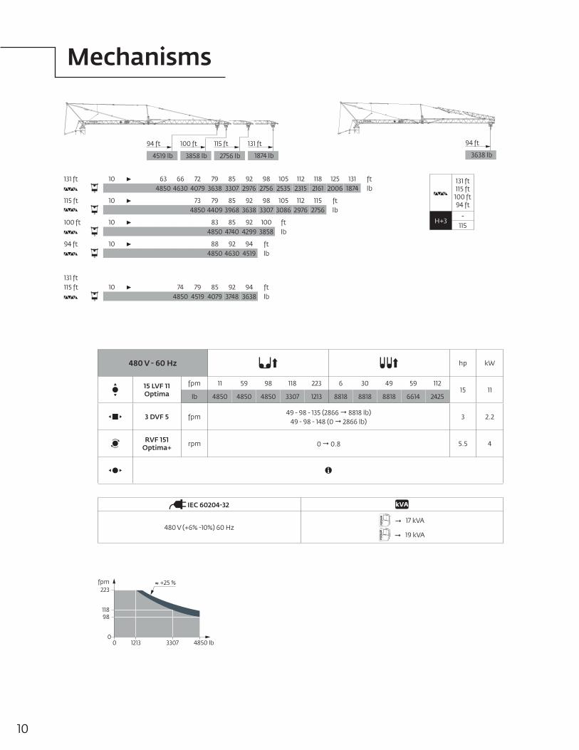
Mechanisms
3638 lb
94 ft
1874 lb
115 ft100 ft 131 ft
2756 lb3858 lb
94 ft
4519 lb
131 ft 10 63 66 72 79 85 92 98 105 112 118 125 131 ft4850 4630 4079 3638 3307 2976 2756 2535 2315 2161 2006 1874 lb
115 ft 10 73 79 85 92 98 105 112 115 ft4850 4409 3968 3638 3307 3086 2976 2756 lb
100 ft 10 83 85 92 100 ft4850 4740 4299 3858 lb
94 ft 10 88 92 94 ft4850 4630 4519 lb
131 ft115 ft 10 74 79 85 92 94 ft
4850 4519 4079 3748 3638 lb
fpm223
11898
4850 lb330712130
0
+25 %
480 V - 60 Hz hp kW
15 LVF 11 Optima
fpm 11 59 98 118 223 6 30 49 59 11215 11
lb 4850 4850 4850 3307 1213 8818 8818 8818 6614 2425
3 DVF 5 fpm49 - 98 - 135 (2866 8818 lb)
49 - 98 - 148 (0 2866 lb)3 2.2
RVF 151 Optima+ rpm 0 0.8 5.5 4
IEC 60204-32
480 V (+6% -10%) 60 Hz 17 kVA
19 kVA
131 ft115 ft100 ft94 ft
H+3-
115
11Potain Igo T 70 ATHIS CHART IS ONLY A GUIDE AND SHOULD NOT BE USED TO OPERATE THE CRANE.
The individual crane’s load chart, operating instructions and other instructional plates must be read and understood prior to operating the crane.
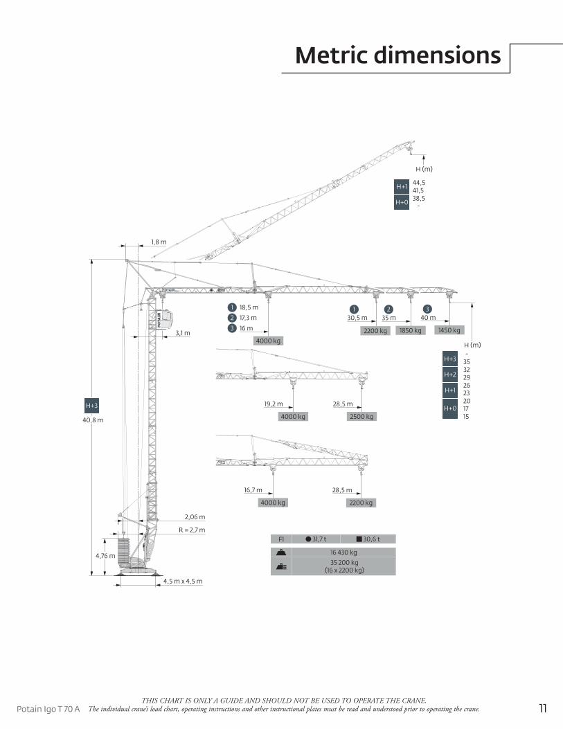
28,5 m
2500 kg
19,2 m
4000 kg
28,5 m
2200 kg
16,7 m
4000 kg
1450 kg
40 m35 m30,5 m321
1850 kg2200 kg3 16 m
2 17,3 m
1 18,5 m
4000 kg
4,5 m x 4,5 m
4,76 m
H+3
40,8 m
R = 2,7 m
2,06 m
1,8 m
3,1 m
H (m)
35-
H+3
2932
H+2
2326
H+1
1720
H+015
H (m)
H+341,544,5H+1
-38,5H+0
F1 31,7 t 30,6 t
16 430 kg
35 200 kg (16 x 2200 kg)
Metric dimensions
12THIS CHART IS ONLY A GUIDE AND SHOULD NOT BE USED TO OPERATE THE CRANE.
The individual crane’s load chart, operating instructions and other instructional plates must be read and understood prior to operating the crane.
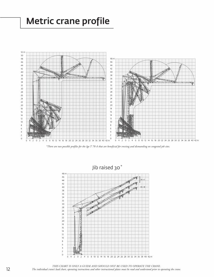
*There are two possible profiles for the Igo T 70 A that are beneficial for erecting and dismantling on congested job sites.
6 4 2 0 2 4 6 8 10 12 14 16 18 20 22 24 26 28 30 32 34 36 38 40 42 m
2
4
6
8
10
12
14
16
18
20
22
24
26
28
30
32
34
36
38
40
42
44
46
48 m
0
50
52 m
6 4 2 0 2 4 6 8 10 12 14 16 18 20 22 24 26 28 30 32 34 36 38 40 42 m
2
4
6
8
10
12
14
16
18
20
22
24
26
28
30
32
34
36
38
40
42
44
46
48
0
6 4 2 0 2 4 6 8 10 12 14 16 18 20 22 24 26 28 30 32 34 36 38 40 42 m
2
4
6
8
10
12
14
16
18
20
22
24
26
28
30
32
34
36
38
40
42
44
46
48 m
0
H + 1
H + 0
Jib raised 30˚
Metric crane profile
13Potain Igo T 70 ATHIS CHART IS ONLY A GUIDE AND SHOULD NOT BE USED TO OPERATE THE CRANE.
The individual crane’s load chart, operating instructions and other instructional plates must be read and understood prior to operating the crane.
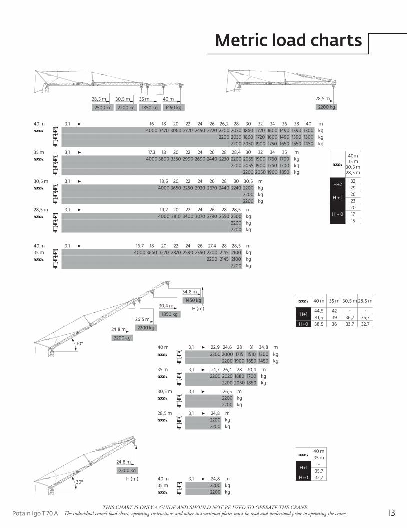
40 m 35 m 30,5 m 28,5 m
H+144,5 42 - -41,5 39 36,7 35,7
H+0 38,5 36 33,7 32,7
2200 kg
28,5 m
1450 kg
35 m30,5 m 40 m
1850 kg2200 kg
28,5 m
2500 kg
40 m 3,1 16,7 18 20 22 24 26 27,4 28 28,5 m35 m 4000 3660 3220 2870 2590 2350 2200 2145 2100 kg
2200 2145 2100 kg2200 kg
40 m 3,1 16 18 20 22 24 26 26,2 28 30 32 34 36 38 40 m4000 3470 3060 2720 2450 2220 2200 2030 1860 1720 1600 1490 1390 1300 kg
2200 2030 1860 1720 1600 1490 1390 1300 kg2200 2050 1900 1750 1650 1550 1450 kg
35 m 3,1 17,3 18 20 22 24 26 28 28,4 30 32 34 35 m4000 3800 3350 2990 2690 2440 2230 2200 2055 1900 1760 1700 kg
2200 2055 1900 1760 1700 kg2200 2050 1900 1850 kg
30,5 m 3,1 18,5 20 22 24 26 28 30 30,5 m4000 3650 3250 2930 2670 2440 2240 2200 kg
2200 kg2200 kg
28,5 m 3,1 19,2 20 22 24 26 28 28,5 m4000 3810 3400 3070 2790 2550 2500 kg
2200 kg2200 kg
30°2200 kg
24,8 m
26,5 m
2200 kg
30,4 m
1850 kgH (m)
34,8 m
1450 kg
40 m 3,1 22,9 24,6 28 31 34,8 m2200 2000 1715 1510 1300 kg
2200 1900 1650 1450 kg
35 m 3,1 24,7 26,4 28 30,4 m2200 2020 1880 1700 kg
2200 2050 1850 kg
30,5 m 3,1 26,5 m2200 kg2200 kg
28,5 m 3,1 24,8 m2200 kg2200 kg
30°
24,8 m
2200 kg
H (m) 40 m 3,1 24,8 m35 m 2200 kg
2200 kg
40 m35 m
H+1-
35,7H+0 32,7
Metric load charts
40m35 m
30,5 m28,5 m
H+23229
H + 12623
H + 0201715
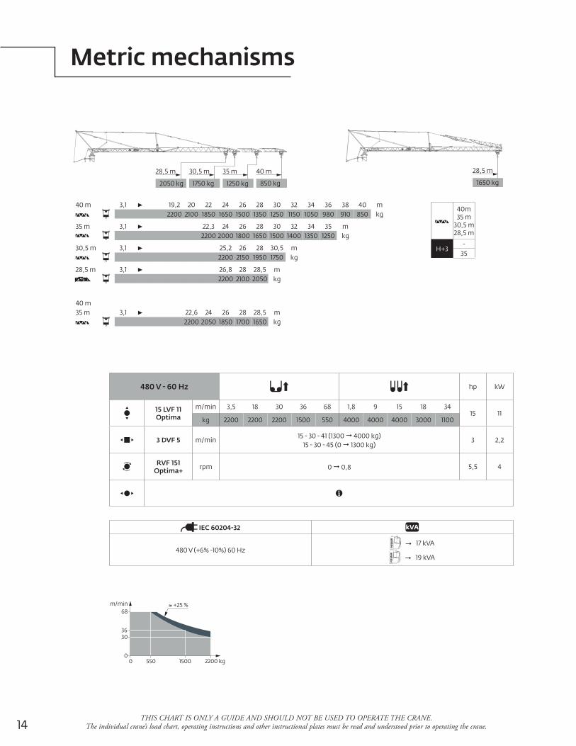
14THIS CHART IS ONLY A GUIDE AND SHOULD NOT BE USED TO OPERATE THE CRANE.
The individual crane’s load chart, operating instructions and other instructional plates must be read and understood prior to operating the crane.
1650 kg
28,5 m
850 kg
35 m30,5 m 40 m
1250 kg1750 kg
28,5 m
2050 kg
40 m 3,1 19,2 20 22 24 26 28 30 32 34 36 38 40 m2200 2100 1850 1650 1500 1350 1250 1150 1050 980 910 850 kg
35 m 3,1 22,3 24 26 28 30 32 34 35 m2200 2000 1800 1650 1500 1400 1350 1250 kg
30,5 m 3,1 25,2 26 28 30,5 m2200 2150 1950 1750 kg
28,5 m 3,1 26,8 28 28,5 m2200 2100 2050 kg
40 m35 m 3,1 22,6 24 26 28 28,5 m
2200 2050 1850 1700 1650 kg
m/min68
3630
2200 kg15005500
0
+25 %
480 V - 60 Hz hp kW
15 LVF 11 Optima
m/min 3,5 18 30 36 68 1,8 9 15 18 3415 11
kg 2200 2200 2200 1500 550 4000 4000 4000 3000 1100
3 DVF 5 m/min15 - 30 - 41 (1300 4000 kg)
15 - 30 - 45 (0 1300 kg)3 2,2
RVF 151 Optima+ rpm 0 0,8 5,5 4
IEC 60204-32
480 V (+6% -10%) 60 Hz 17 kVA
19 kVA
Metric mechanisms
40m35 m
30,5 m28,5 m
H+3-
35
15Potain Igo T 70 A
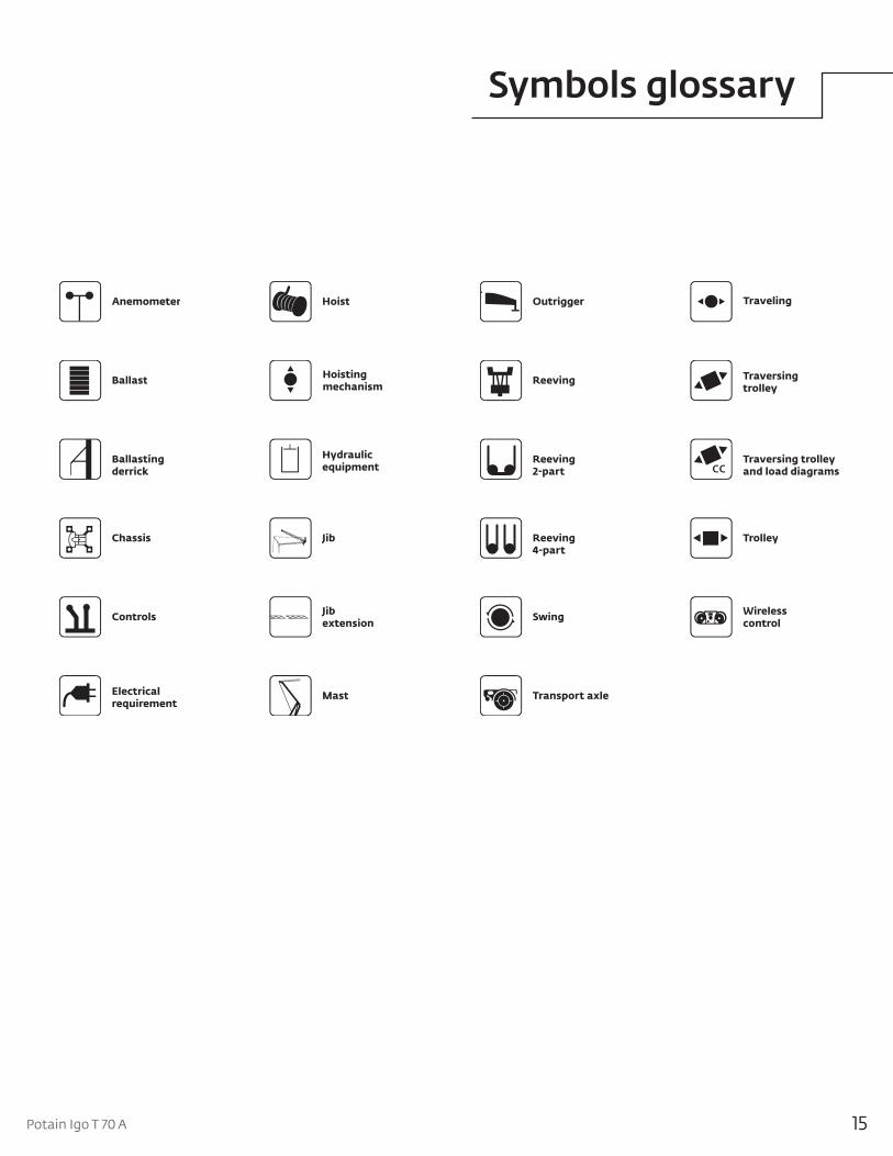
Symbols glossary
GMA Potain Glossary 2.2.09
Anemometer
Ballast
Ballastingderrick
Chassis
Controls
Electricalrequirement
Hoist
Hoistingmechanism
Hydraulicequipment
Jib
Jibextension
Mast
Outrigger
Reeving
Reeving2-part
Reeving4-part
Swing
Transport axle
Traveling
Traversingtrolley
Traversing trolleyand load diagrams
Trolley
Wirelesscontrol

16
Notes

17Potain Igo T 70 A
Notes
This document is non-contractual. Constant improvement and engineering progress make it necessary that we reserve the right to make specification, equipment, and price changes without notice. Illustrations shown may include optional equipment and accessories and may not include all standard equipment.
AmericasBrazilAlphavilleMexicoMonterreyChileSantiago
Europe, Middle East & AfricaAlgeriaHydraCzech RepublicNetvoriceFranceBaudemontCergyDecinesGermanyLangenfeldHungaryBudapestItalyParabiagoNetherlandsBredaPolandWarsaw
PortugalBaltarLisbonRussiaMoscowU.A.E.DubaiU.K.Gawcott
Asia - PacificAustraliaBrisbaneMelbourneSydneyChinaBeijingXi’anKoreaSeoulIndiaHyderabadPunePhilippinesMakati CitySingapore
FactoriesBrazilAlphavilleChinaTaiAnZhangjiagangFranceCharlieuLa ClayetteMoulinsGermanyWilhelmshavenIndiaPuneItalyNiella TanaroPortugalBaltarFânzeresSlovakiaSarisUSAManitowoc Port WashingtonShady Grove
Regional offices
Manitowoc - Asia Pacific Shanghai, China Tel: +86 21 6457 0066Fax: +86 21 6457 4955
Manitowoc - Europe, Middle East & Africa Ecully, France Tel: +33 (0)4 72 18 20 20 Fax: +33 (0)4 72 18 20 00
Manitowoc - Americas Manitowoc, Wisconsin, USA Tel: +1 920 684 6621 Fax: +1 920 683 6277
Shady Grove, Pennsylvania, USA Tel: +1 717 597 8121 Fax: +1 717 597 4062
©2009 ManitowocPrinted in USAForm No. Igo T 70Part No. 07-013 - 2M - 1009 www.manitowoc.com
Regional headquarters