Embed Size (px)
Citation preview
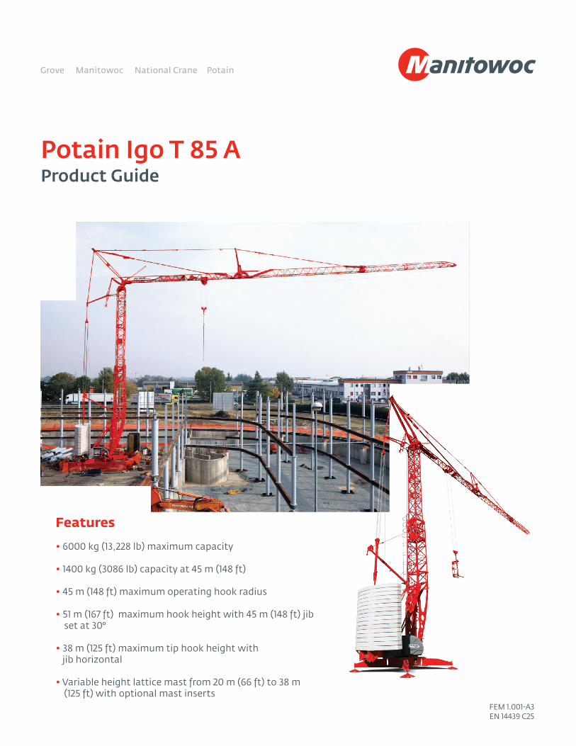
Potain Igo T 85 AProduct Guide
Features • 6000 kg (13,228 lb) maximum capacity
• 1400 kg (3086 lb) capacity at 45 m (148 ft)
• 45 m (148 ft) maximum operating hook radius
• 51 m (167 ft) maximum hook height with 45 m (148 ft) jib set at 30°
• 38 m (125 ft) maximum tip hook height with jib horizontal
• Variable height lattice mast from 20 m (66 ft) to 38 m (125 ft) with optional mast inserts
FEM 1.001-A3EN 14439 C25
2
Features
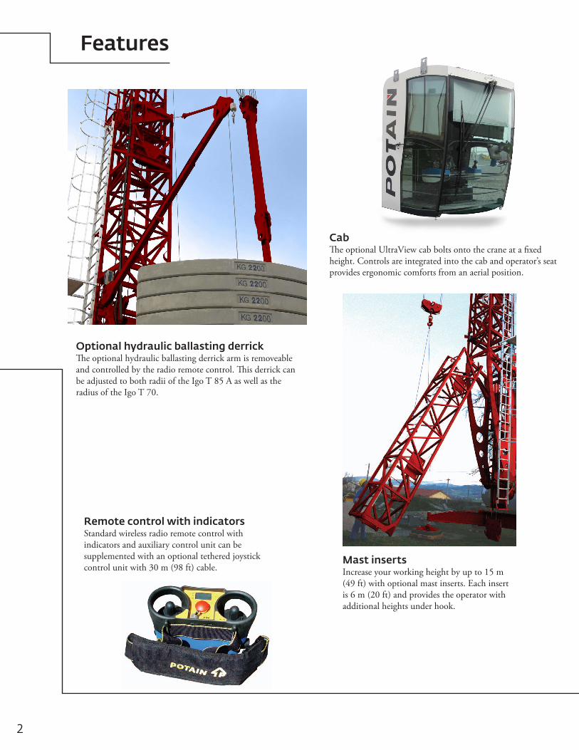
Mast insertsIncrease your working height by up to 15 m (49 ft) with optional mast inserts. Each insert is 6 m (20 ft) and provides the operator with additional heights under hook.
CabThe optional UltraView cab bolts onto the crane at a fixed height. Controls are integrated into the cab and operator’s seat provides ergonomic comforts from an aerial position.
Optional hydraulic ballasting derrickThe optional hydraulic ballasting derrick arm is removeable and controlled by the radio remote control. This derrick can be adjusted to both radii of the Igo T 85 A as well as the radius of the Igo T 70.
Remote control with indicatorsStandard wireless radio remote control with indicators and auxiliary control unit can be supplemented with an optional tethered joystick control unit with 30 m (98 ft) cable.
Contents
Specifications 4
Transport 5
Weights 6
Dimensions 7
Crane profile 8
Load charts 9
Mechanisms 10
Metric dimension 11
Metric crane profile 12
Metric load charts 13
Metric mechanisms 14
Symbols glossary 15
4*Denotes optional equipment
**Requires optional anemometer
Specifications
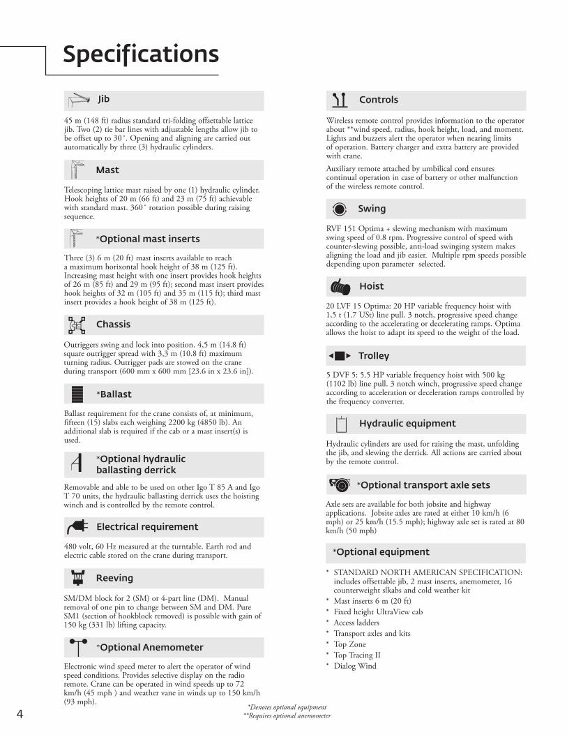
Jib
45 m (148 ft) radius standard tri-folding offsettable lattice jib. Two (2) tie bar lines with adjustable lengths allow jib to be offset up to 30˚. Opening and aligning are carried out automatically by three (3) hydraulic cylinders.
Jib
Three (3) 6 m (20 ft) mast inserts available to reach a maximum horixontal hook height of 38 m (125 ft). Increasing mast height with one insert provides hook heights of 26 m (85 ft) and 29 m (95 ft); second mast insert provides hook heights of 32 m (105 ft) and 35 m (115 ft); third mast insert provides a hook height of 38 m (125 ft).
Telescoping lattice mast raised by one (1) hydraulic cylinder. Hook heights of 20 m (66 ft) and 23 m (75 ft) achievable with standard mast. 360˚ rotation possible during raising sequence.
Outriggers swing and lock into position. 4,5 m (14.8 ft) square outrigger spread with 3,3 m (10.8 ft) maximum turning radius. Outrigger pads are stowed on the crane during transport (600 mm x 600 mm [23.6 in x 23.6 in]).
Ballast requirement for the crane consists of, at minimum, fifteen (15) slabs each weighing 2200 kg (4850 lb). An additional slab is required if the cab or a mast insert(s) is used.
Removable and able to be used on other Igo T 85 A and Igo T 70 units, the hydraulic ballasting derrick uses the hoisting winch and is controlled by the remote control.
480 volt, 60 Hz measured at the turntable. Earth rod and electric cable stored on the crane during transport.
SM/DM block for 2 (SM) or 4-part line (DM). Manual removal of one pin to change between SM and DM. Pure SM1 (section of hookblock removed) is possible with gain of 150 kg (331 lb) lifting capacity.
Wireless remote control provides information to the operator about **wind speed, radius, hook height, load, and moment. Lights and buzzers alert the operator when nearing limits of operation. Battery charger and extra battery are provided with crane. Auxiliary remote attached by umbilical cord ensures continual operation in case of battery or other malfunction of the wireless remote control.
Electronic wind speed meter to alert the operator of wind speed conditions. Provides selective display on the radio remote. Crane can be operated in wind speeds up to 72 km/h (45 mph ) and weather vane in winds up to 150 km/h (93 mph).
RVF 151 Optima + slewing mechanism with maximum swing speed of 0.8 rpm. Progressive control of speed with counter-slewing possible, anti-load swinging system makes aligning the load and jib easier. Multiple rpm speeds possible depending upon parameter selected.
20 LVF 15 Optima: 20 HP variable frequency hoist with 1,5 t (1.7 USt) line pull. 3 notch, progressive speed change according to the accelerating or decelerating ramps. Optima allows the hoist to adapt its speed to the weight of the load.
5 DVF 5: 5.5 HP variable frequency hoist with 500 kg (1102 lb) line pull. 3 notch winch, progressive speed change according to acceleration or deceleration ramps controlled by the frequency converter.
Hydraulic cylinders are used for raising the mast, unfolding the jib, and slewing the derrick. All actions are carried about by the remote control.
Axle sets are available for both jobsite and highway applications. Jobsite axles are rated at either 10 km/h (6 mph) or 25 km/h (15.5 mph); highway axle set is rated at 80 km/h (50 mph)
* STANDARD NORTH AMERICAN SPECIFICATION: includes offsettable jib, 2 mast inserts, anemometer, 16 counterweight slkabs and cold weather kit
* Mast inserts 6 m (20 ft) * Fixed height UltraView cab * Access ladders * Transport axles and kits * Top Zone * Top Tracing II* Dialog Wind
*Optional mast inserts
Mast
ChassisChassis
*BallastBallast
*Optional hydraulic ballasting derrick
Ballasting Derrick
Electrical requirementElectrical Requirement
ReevingReeving
*Optional AnemometerAnemometer
ControlsControls
SwingSwing
HoistHoist
TrolleyTrolley
Hydraulic equipmentHydraulic Equipment
*Optional transport axle sets
*Optional equipment
5Potain Igo T 85 A
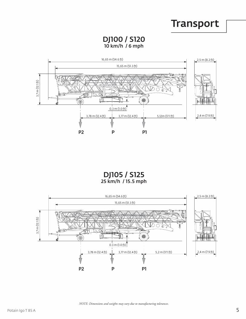
DJ105 / S12525 km/h / 15.5 mph
NOTE: Dimensions and weights may vary due to manufacturing tolerances.
DJ100 / S120 10 km/h / 6 mph
Transport
16,65 m (54.6 ft)
15,65 m (51.3 ft)
2,5 m (8.2 ft)
2,4 m (7.9 ft)5,12m (17.1 ft)3,77 m (12.4 ft)3,78 m (12.4 ft)
0,3 m (1.0 ft)
3,7
m (1
2.1 f
t)
P2 P P1
16,65 m (54.6 ft)
P2 P P1
15,65 m (51.3 ft)
2,5 m (8.2 ft)
2,4 m (7.9 ft)5,2 m (17.1 ft)3,77 m (12.4 ft)3,78 m (12.4 ft)
0.3 m (1.0 ft)
3,7
m (1
2.1 f
t)
6
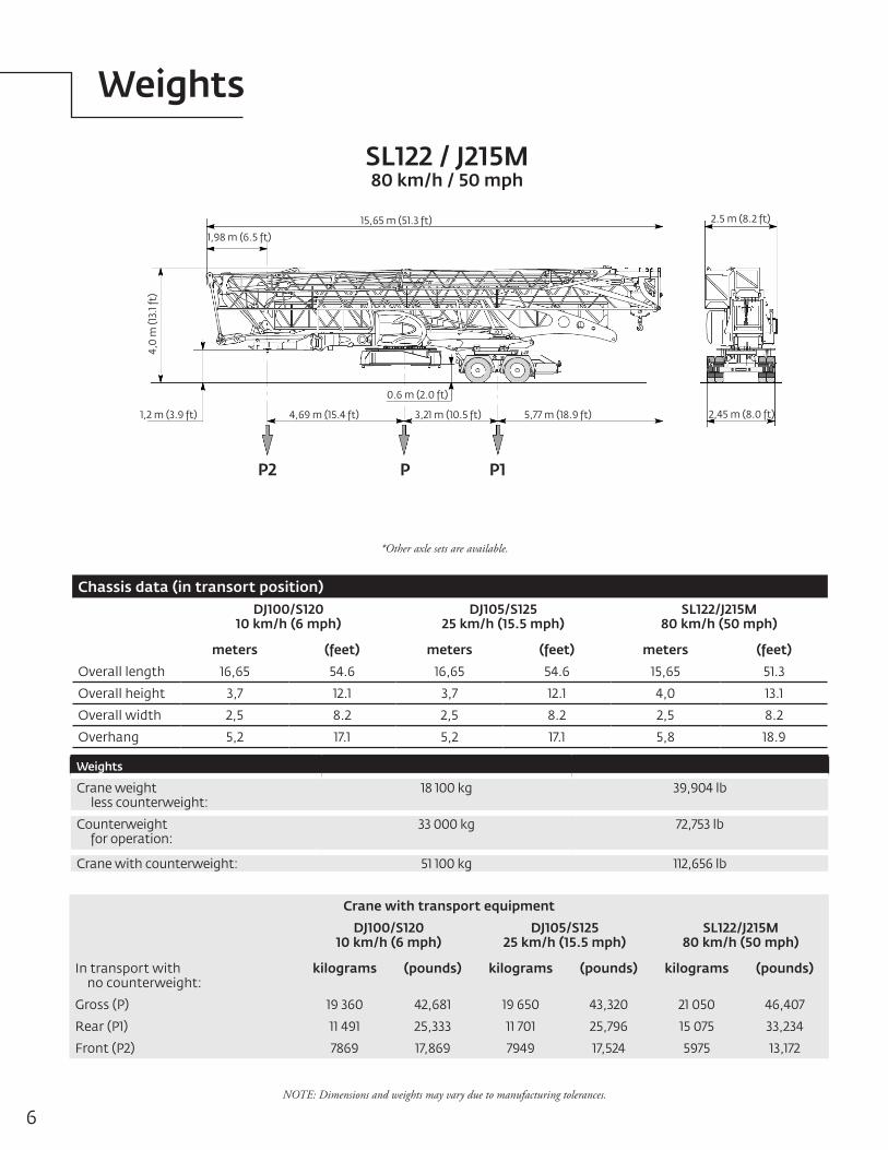
SL122 / J215M80 km/h / 50 mph
NOTE: Dimensions and weights may vary due to manufacturing tolerances.
Weights
*Other axle sets are available.
Chassis data (in transort position)DJ100/S120
10 km/h (6 mph)DJ105/S125
25 km/h (15.5 mph)SL122/J215M
80 km/h (50 mph)
meters (feet) meters (feet) meters (feet)
Overall length 16,65 54.6 16,65 54.6 15,65 51.3
Overall height 3,7 12.1 3,7 12.1 4,0 13.1
Overall width 2,5 8.2 2,5 8.2 2,5 8.2
Overhang 5,2 17.1 5,2 17.1 5,8 18.9
Weights
Crane weight less counterweight:
18 100 kg 39,904 lb
Counterweight for operation:
33 000 kg 72,753 lb
Crane with counterweight: 51 100 kg 112,656 lb
Crane with transport equipment
DJ100/S12010 km/h (6 mph)
DJ105/S12525 km/h (15.5 mph)
SL122/J215M80 km/h (50 mph)
In transport with no counterweight:
kilograms (pounds) kilograms (pounds) kilograms (pounds)
Gross (P) 19 360 42,681 19 650 43,320 21 050 46,407
Rear (P1) 11 491 25,333 11 701 25,796 15 075 33,234
Front (P2) 7869 17,869 7949 17,524 5975 13,172
15,65 m (51.3 ft)
P2 P P1
1,98 m (6.5 ft)
2.5 m (8.2 ft)
2,45 m (8.0 ft)5,77 m (18.9 ft)3,21 m (10.5 ft)4,69 m (15.4 ft)
0.6 m (2.0 ft)
4,0
m (1
3.1 f
t)
1,2 m (3.9 ft)
7Potain Igo T 85 A
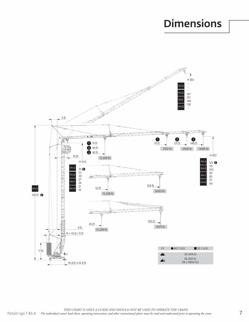
Dimensions
THIS CHART IS ONLY A GUIDE AND SHOULD NOT BE USED TO OPERATE THE CRANE. The individual crane’s load chart, operating instructions and other instructional plates must be read and understood prior to operating the crane
14.8 ft x 14.8 ft
3086 lb3968 lb5512 lb
148 ft131 ft111 ft1 2 3
3 42 ft
2 46 ft
1 51 ft
13,228 lb
H (ft)
--
H+3
167-
H+2
148157
H+1
-138
H+0
13,228 lb2750 kg6063 lb
104 ft52 ft
105 ft
13,228 lb
45 ft
10 ft
5 ft
17 ft
R = 10 ft / 11 ft
9 ft 5071 lb
H (ft)
125-
H+3
105115
H+2
8595
H+1
6675
H+0
H (m)
36-
H+3
3033
H+2
2427
H+1
1821
H+0H+3
136 ft
F1 40.7 USt 35.3 USt
39,904 lb
82,450 lb(16 x 4850 lb)
F1
8
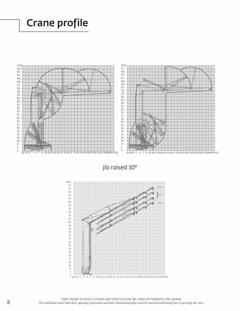
Crane profile
THIS CHART IS ONLY A GUIDE AND SHOULD NOT BE USED TO OPERATE THE CRANE. The individual crane’s load chart, operating instructions and other instructional plates must be read and understood prior to operating the crane.
26 20 13 7 0 7 13 20 2633 39 46 52 59 66 72 79 85 92 98 105112 118 125131 138144151 157 ft
71320263339465259667279859298105112118125131138144151157164171 ft
026 20 13 7 0 7 13 20 2633 39 46 52 59 66 72 79 85 92 98 105112 118 125131 138144151 157 ft
71320263339465259667279859298105112118125131138144151157164171177 ft
0
Jib raised 30°Igo T 85 A: jib raised 30°
26 20 13 7 0 7 13 20 26 33 39 46 52 59 66 72 79 85 92 98 105 112 118 125 131 138 144 151
184 ft
177
171
164
157
151
144
138
131
125
118
112
105
98
92
85
79
72
66
59
52
46
39
33
26
20
13
7
0ft
H +1
H +0
H +2
9Potain Igo T 85 A
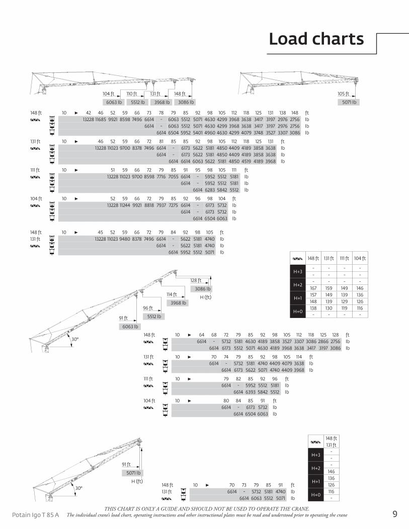
Load charts
THIS CHART IS ONLY A GUIDE AND SHOULD NOT BE USED TO OPERATE THE CRANE. The individual crane’s load chart, operating instructions and other instructional plates must be read and understood prior to operating the crane
148 ft 10 70 73 79 85 91 ft131 ft 6614 - 5732 5181 4740 lb
6614 6063 5512 5071 lb
148 ft 10 42 46 52 59 66 73 78 79 85 92 98 105 112 118 125 131 138 148 ft13228 11685 9921 8598 7496 6614 - 6063 5512 5071 4630 4299 3968 3638 3417 3197 2976 2756 lb
6614 - 6063 5512 5071 4630 4299 3968 3638 3417 3197 2976 2756 lb6614 6504 5952 5401 4960 4630 4299 4079 3748 3527 3307 3086 lb
131 ft 10 46 52 59 66 72 81 85 85 92 98 105 112 118 125 131 ft13228 11023 9700 8378 7496 6614 - 6173 5622 5181 4850 4409 4189 3858 3638 lb
6614 - 6173 5622 5181 4850 4409 4189 3858 3638 lb6614 6614 6063 5622 5181 4850 4519 4189 3968 lb
111 ft 10 51 59 66 72 79 85 91 95 98 105 111 ft13228 11023 9700 8598 7716 7055 6614 - 5952 5512 5181 lb
6614 - 5952 5512 5181 lb6614 6283 5842 5512 lb
104 ft 10 52 59 66 72 79 85 92 96 98 104 ft13228 11244 9921 8818 7937 7275 6614 - 6173 5732 lb
6614 - 6173 5732 lb6614 6504 6063 lb
148 ft 10 64 68 72 79 85 92 98 105 112 118 125 128 ft6614 - 5732 5181 4630 4189 3858 3527 3307 3086 2866 2756 lb
6614 6173 5512 5071 4630 4189 3968 3638 3417 3197 3086 lb
131 ft 10 70 74 79 85 92 98 105 114 ft6614 - 5732 5181 4740 4409 4079 3638 lb
6614 6173 5622 5071 4740 4409 3968 lb
111 ft 10 79 82 85 92 96 ft6614 - 5952 5512 5181 lb
6614 6393 5842 5512 lb
104 ft 10 80 84 85 91 ft6614 - 6173 5732 lb
6614 6504 6063 lb
148 ft131 ft
H+3--
H+2-
146
H+1136126
H+0116
-
148 ft 131 ft 111 ft 104 ft
H+3- - - -- - - -
H+2- - - -
167 159 149 146
H+1157 149 139 136148 139 129 126
H+0138 130 119 116
- - - -
3086 lb
131 ft 110 ft 148 ft
3968 lb5512 lb
104 ft
6063 lb 5071 lb
105 ft
30°
6063 lb
91 ft
96 ft
5512 lb
114 ft
3968 lbH (ft)
128 ft
3086 lb
30°
91 ft
5071 lb
H (ft)
148 ft 10 45 52 59 66 72 79 84 92 98 105 ft131 ft 13228 11023 9480 8378 7496 6614 - 5622 5181 4740 lb
6614 - 5622 5181 4740 lb6614 5952 5512 5071 lb
10
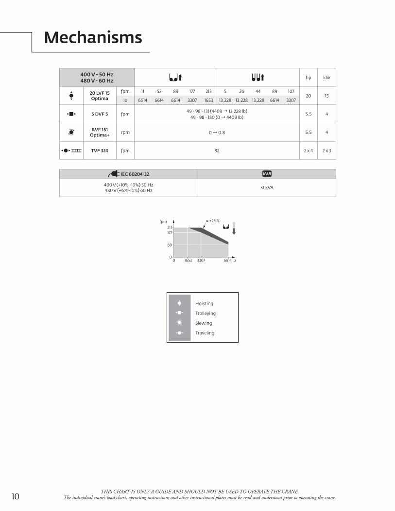
Mechanisms
THIS CHART IS ONLY A GUIDE AND SHOULD NOT BE USED TO OPERATE THE CRANE. The individual crane’s load chart, operating instructions and other instructional plates must be read and understood prior to operating the crane.
Hoisting
Trolleying
Slewing
Traveling
400 V - 50 Hz480 V - 60 Hz
hp kW
20 LVF 15 Optima
fpm 11 52 89 177 213 5 26 44 89 10720 15
lb 6614 6614 6614 3307 1653 13,228 13,228 13,228 6614 3307
5 DVF 5 fpm49 - 98 - 131 (4409 13,228 lb)
49 - 98 - 180 (0 4409 lb)5.5 4
RVF 151 Optima+ rpm 0 0.8 5.5 4
TVF 324 fpm 82 2 x 4 2 x 3
IEC 60204-32
400 V (+10% -10%) 50 Hz480 V (+6% -10%) 60 Hz 31 kVA
6614 lb0
fpm
0
89
+25 %
3307 1653
177213
11Potain Igo T 85 A
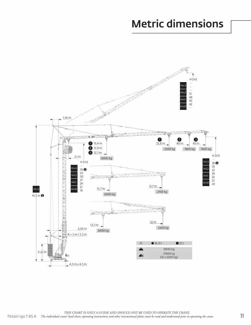
Metric dimensions
THIS CHART IS ONLY A GUIDE AND SHOULD NOT BE USED TO OPERATE THE CRANE. The individual crane’s load chart, operating instructions and other instructional plates must be read and understood prior to operating the crane
4,5 m x 4,5 m
1400 kg1800 kg2500 kg
45 m40 m33,8 m1 2 3
3 12,7 m
2 13,9 m
1 15,4 m
6000 kg
H (m)
--
H+3
51-
H+2
4548
H+1
-42
H+0
6000 kg2750 kg2750 kg
31,7 m15,7 m
32 m
6000 kg
13,7 m
3,1 m
1,56 m
5,22 m
R = 3 m / 3,3 m
2,65 m 2300 kg
H (m)
38-
H+3
3235
H+2
2629
H+1
2023
H+0
H (m)
36-
H+3
3033
H+2
2427
H+1
1821
H+0H+3
41,5 m
F1 36,9 t 32 t
18100 kg
37400 kg(16 x 2200 kg) F1
12
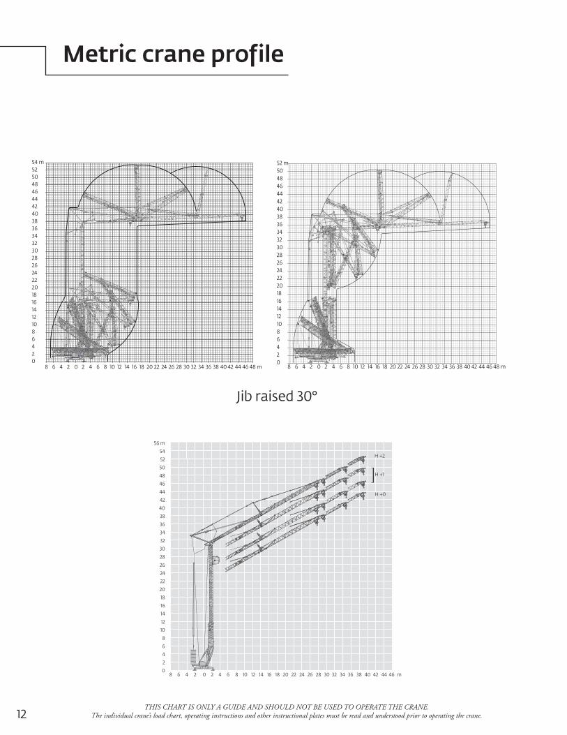
Metric crane profile
THIS CHART IS ONLY A GUIDE AND SHOULD NOT BE USED TO OPERATE THE CRANE. The individual crane’s load chart, operating instructions and other instructional plates must be read and understood prior to operating the crane.
8 6 4 2 0 2 4 6 8 10 12 14 16 18 20 22 24 26 28 30 32 34 36 38 40 42 44 46 48 m
24681012141618202224262830323436384042444648505254 m
08 6 4 2 0 2 4 6 8 10 12 14 16 18 20 22 24 26 28 30 32 34 36 38 40 42 44 46 48 m
246810121416182022242628303234363840424446485052 m
0
Jib raised 30°
8 6 4 2 0 2 4 6 8 10 12 14 16 18 20 22 24 26 28 30 32 34 36 38 40 42 44 46 m
56 m
54
52
50
48
46
44
42
40
38
36
34
32
30
28
26
24
22
20
18
16
14
12
10
8
6
4
2
0
Igo T 85 A: jib raised 30°
H +1
H +0
H +2
13Potain Igo T 85 A
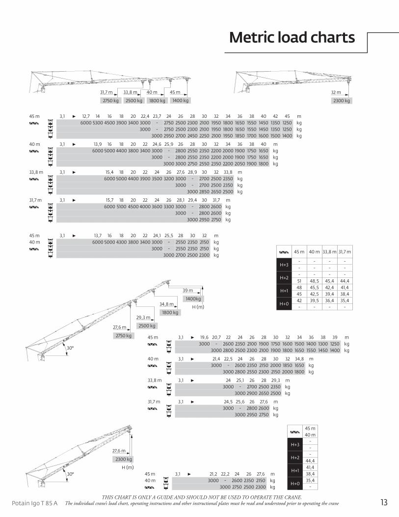
Metric load charts
THIS CHART IS ONLY A GUIDE AND SHOULD NOT BE USED TO OPERATE THE CRANE. The individual crane’s load chart, operating instructions and other instructional plates must be read and understood prior to operating the crane
45 m 3,1 13,7 16 18 20 22 24,1 25,5 28 30 32 m40 m 6000 5000 4300 3800 3400 3000 - 2550 2350 2150 kg
3000 - 2550 2350 2150 kg3000 2700 2500 2300 kg
45 m 3,1 21,2 22,2 24 26 27,6 m40 m 3000 - 2600 2350 2150 kg
3000 2750 2500 2300 kg
45 m 3,1 12,7 14 16 18 20 22,4 23,7 24 26 28 30 32 34 36 38 40 42 45 m6000 5300 4500 3900 3400 3000 - 2750 2500 2300 2100 1950 1800 1650 1550 1450 1350 1250 kg
3000 - 2750 2500 2300 2100 1950 1800 1650 1550 1450 1350 1250 kg3000 2950 2700 2450 2250 2100 1950 1850 1700 1600 1500 1400 kg
40 m 3,1 13,9 16 18 20 22 24,6 25,9 26 28 30 32 34 36 38 40 m6000 5000 4400 3800 3400 3000 - 2800 2550 2350 2200 2000 1900 1750 1650 kg
3000 - 2800 2550 2350 2200 2000 1900 1750 1650 kg3000 3000 2750 2550 2350 2200 2050 1900 1800 kg
33,8 m 3,1 15,4 18 20 22 24 26 27,6 28,9 30 32 33,8 m6000 5000 4400 3900 3500 3200 3000 - 2700 2500 2350 kg
3000 - 2700 2500 2350 kg3000 2850 2650 2500 kg
31,7 m 3,1 15,7 18 20 22 24 26 28,1 29,4 30 31,7 m6000 5100 4500 4000 3600 3300 3000 - 2800 2600 kg
3000 - 2800 2600 kg3000 2950 2750 kg
45 m 3,1 19,6 20,7 22 24 26 28 30 32 34 36 38 39 m3000 - 2600 2350 2100 1900 1750 1600 1500 1400 1300 1250 kg
3000 2800 2500 2300 2100 1900 1800 1650 1550 1450 1400 kg
40 m 3,1 21,4 22,5 24 26 28 30 32 34,8 m3000 - 2600 2350 2150 2000 1850 1650 kg
3000 2800 2550 2300 2150 2000 1800 kg
33,8 m 3,1 24 25,1 26 28 29,3 m3000 - 2700 2500 2350 kg
3000 2900 2650 2500 kg
31,7 m 3,1 24,5 25,6 26 27,6 m3000 - 2800 2600 kg
3000 2950 2750 kg
45 m40 m
H+3--
H+2-
44,4
H+141,438,4
H+035,4
-
45 m 40 m 33,8 m 31,7 m
H+3- - - -- - - -
H+2- - - -
51 48,5 45,4 44,4
H+148 45,5 42,4 41,445 42,5 39,4 38,4
H+042 39,5 36,4 35,4- - - -
1400 kg
40 m33,8 m 45 m
1800 kg2500 kg
31,7 m
2750 kg 2300 kg
32 m
30°
2750 kg
27,6 m
29,3 m
2500 kg
34,8 m
1800 kgH (m)
39 m
1400kg
30°
27,6 m
2300 kg
H (m)
14
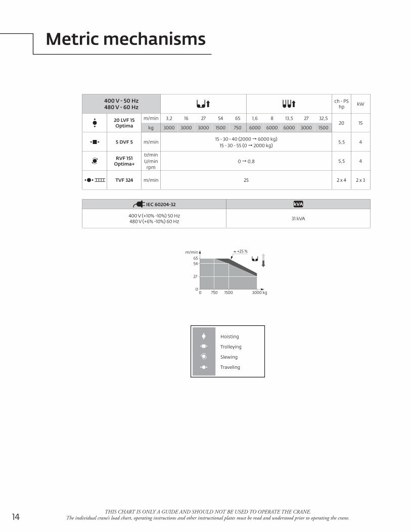
Metric mechanisms
THIS CHART IS ONLY A GUIDE AND SHOULD NOT BE USED TO OPERATE THE CRANE. The individual crane’s load chart, operating instructions and other instructional plates must be read and understood prior to operating the crane.
Hoisting
Trolleying
Slewing
Traveling
400 V - 50 Hz480 V - 60 Hz
ch - PS hp kW
20 LVF 15 Optima
m/min 3,2 16 27 54 65 1,6 8 13,5 27 32,520 15
kg 3000 3000 3000 1500 750 6000 6000 6000 3000 1500
5 DVF 5 m/min15 - 30 - 40 (2000 6000 kg)
15 - 30 - 55 (0 2000 kg)5,5 4
RVF 151 Optima+
tr/min U/min
rpm0 0,8 5,5 4
TVF 324 m/min 25 2 x 4 2 x 3
IEC 60204-32
400 V (+10% -10%) 50 Hz480 V (+6% -10%) 60 Hz 31 kVA
3000 kg0
m/min
0
27
+25 %
1500750
5465
15Potain Igo T 85 A
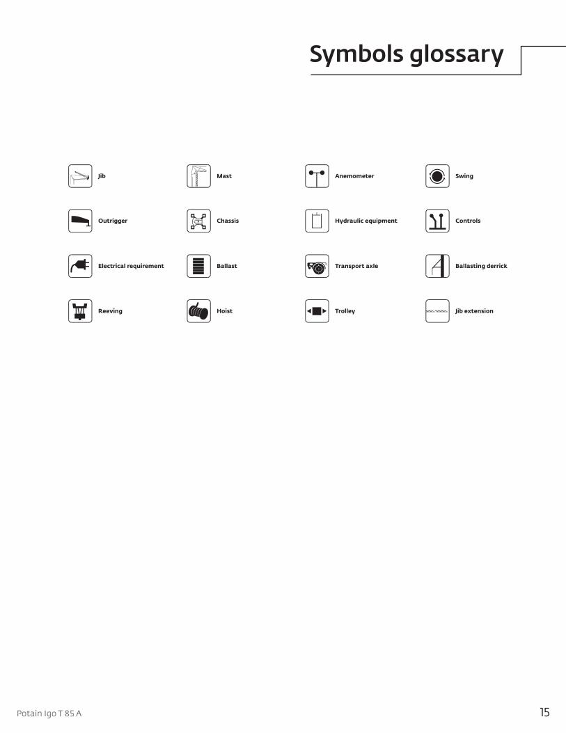
Controls
Ballasting derrick
Jib
ChassisOutrigger
BallastElectrical requirement
Reeving
Hydraulic equipment
Trolley
Swing
Transport axle
Mast Anemometer
Hoist Jib extension
Potain GMA Glossary 4.4.07
Symbols glossary
©2011 ManitowocForm No. Igo T 85 A PGPart No. 11-002-2M-0811 www.manitowoc.com
This document is non-contractual. Constant improvement and engineering progress make it necessary that we reserve the right to make specification, equipment, and price changes without notice. Illustrations shown may include optional equipment and accessories and may not include all standard equipment.
Regional offices
ChinaShanghai, China Tel: +86 21 6457 0066Fax: +86 21 6457 4955
Greater Asia-Pacific Singapore Tel: +65 6264 1188 Fax: +65 6862 4040
Europe, Middle East, Africa Ecully, France Tel: +33 (0)4 72 18 20 20 Fax: +33 (0)4 72 18 20 00
Americas Manitowoc, Wisconsin, USA Tel: +1 920 684 6621 Fax: +1 920 683 6277
Shady Grove, Pennsylvania, USA Tel: +1 717 597 8121 Fax: +1 717 597 4062
Regional headquarters
Manitowoc Cranes
ChinaBeijingChengduGuangzhouXian
Greater Asia-PacificAustraliaAdelaideBrisbaneMelbourneSydneyIndiaCalcuttaChennaiDelhiHyderabadPuneKoreaSeoulPhilippinesMakati CitySingapore
FactoriesBrazilAlphavilleChinaTaiAnZhangjiagangFranceCharlieuMoulinsGermanyWilhelmshavenIndiaPuneItalyNiella TanaroPortugalBaltarFânzeresSlovakiaSarisUSAManitowoc Port WashingtonShady Grove
AmericasBrazilAlphavilleMexicoMonterreyChileSantiago
Europe, Middle East, AfricaCzech RepublicNetvoriceFranceBaudemontCergyDecinesGermanyLangenfeldHungaryBudapestItalyLainateNetherlandsBredaPolandWarsawPortugalBaltarRussiaMoscowU.A.E.DubaiU.K.Buckingham