Embed Size (px)
Citation preview

PRO
DU
CT
DES
CR
IPTI
ON
SAS FREYSSINET PRODUCTS COMPANY ZA DU MONAY - BP 18
71210 SAINT EUSEBE France Tel. +33.3.85.73.69.00
Ref: BGT-001 Revision: 0
November 2017
PRO
DU
CT
DES
CR
IPTI
ON
Post-Tensioning
Freyssibar
Freyssibar


COPYRIGHT This document is the exclusive property of FREYSSINET. It is confidential and may not be used, reproduced or communicated either in whole or in part, in any form or manner without the prior written agreement of FREYSSINET. All drawings and pictures aren’t contractual. REVISION INDICES FOLLOW -UP TABLE
Rev Date Modification Prepared by Checked by Approved by
0 04/04/17 First issue L. FURLAN C. GAUCHERAND E. THIBOEUF

TABLE OF CONTENTS
1. INTRODUCTION ...................................................................................................................................................................................... 1
1.1. Scope of the document .................................................................................................................................................................. 1
1.2. Post-tensioning ................................................................................................................................................................................... 1
1.3. Freyssibars’ scope of use .............................................................................................................................................................. 2
1.4. Design ........................................................................................................................................................................................................ 2 1.4.1. Bars...................................................................................................................................................................................................................2 1.4.2. System ............................................................................................................................................................................................................3
1.5. Manufacturing...................................................................................................................................................................................... 3
1.6. Installation ............................................................................................................................................................................................... 3
1.7. Surveillance ............................................................................................................................................................................................. 3
2. APPLICABLE DOCUMENTATIONS .............................................................................................................................................. 4
2.1. Specific documentation ................................................................................................................................................................. 4
2.2. Standards for components ........................................................................................................................................................... 4 2.2.1. Bars Freyssibar ..........................................................................................................................................................................................4 2.2.2. Accessories ..................................................................................................................................................................................................5
2.3. Standards for manufacturing ...................................................................................................................................................... 5
2.4. Standards for control ........................................................................................................................................................................ 5
3. DESCRIPTION OF THE FREYSSIBAR SYSTEM ..................................................................................................................... 6
3.1. Overview ................................................................................................................................................................................................... 6
3.2. Bars .............................................................................................................................................................................................................. 7
3.3. Anchorage ............................................................................................................................................................................................... 9 3.3.1. Flat Anchorage...........................................................................................................................................................................................9 3.3.2. Type 1 Spherical Anchorage ......................................................................................................................................................... 10 3.3.3. Type 2 Spherical Anchorage ......................................................................................................................................................... 11 3.3.4. Embedded anchorage ....................................................................................................................................................................... 12
3.4. Coupling ................................................................................................................................................................................................ 13 3.4.1. Movable coupler .................................................................................................................................................................................. 13 3.4.2. Fixed coupler ......................................................................................................................................................................................... 13
3.5. Accessories .......................................................................................................................................................................................... 14 3.5.1. Nut for flat anchorage ..................................................................................................................................................................... 14 3.5.2. Washer for flat anchorage ............................................................................................................................................................. 14 3.5.3. Spherical nut for type 1 anchorage .......................................................................................................................................... 14 3.5.4. Spherical nut for type 2 anchorage ......................................................................................................................................... 15 3.5.5. Spherical washer for type 2 anchorage .................................................................................................................................. 15 3.5.6. Bearing plate for flat and type 2 anchorage ........................................................................................................................ 15 3.5.7. Spherical plate for type 1 anchorage ....................................................................................................................................... 15 3.5.8. Bearing plate for flat and type 2 anchorage for injection ............................................................................................ 16 3.5.9. Spherical plate for type 1 anchorage for injection ........................................................................................................... 16 3.5.10. Bearing plate for flat and type 2 anchorage for injection + tube ...................................................................... 16

3.5.11. Spherical plate for type 1 anchorage for injection + tube ..................................................................................... 16 3.5.12. Coupler ................................................................................................................................................................................................. 17 3.5.13. Caps........................................................................................................................................................................................................ 17 3.5.14. Sheath ................................................................................................................................................................................................... 19 3.5.15. Injection accessories .................................................................................................................................................................... 20
3.6. Corrosion protection ...................................................................................................................................................................... 21 3.6.1. Grout ........................................................................................................................................................................................................... 21 3.6.2. Wax............................................................................................................................................................................................................... 22 3.6.3. Heat shrink sleeve cover.................................................................................................................................................................. 23 3.6.4. Galvanization .......................................................................................................................................................................................... 24 3.6.5. Denso .......................................................................................................................................................................................................... 24
3.7. Marking .................................................................................................................................................................................................. 25 3.7.1. Bars............................................................................................................................................................................................................... 25 3.7.2. Accessories .............................................................................................................................................................................................. 25
4. DESIGN ....................................................................................................................................................................................................... 26
4.1. Calculation ........................................................................................................................................................................................... 26
4.2. Testing .................................................................................................................................................................................................... 26
4.3. Type of use .......................................................................................................................................................................................... 26
4.4. Choice of the adapted solution .............................................................................................................................................. 26
4.5. Warranty ................................................................................................................................................................................................ 28
5. MANUFACTURING & LOGISTICS .............................................................................................................................................. 30
5.1. Resources ............................................................................................................................................................................................. 30
5.2. Manufacturing................................................................................................................................................................................... 31 5.2.1. Site of production & distribution ................................................................................................................................................. 31 5.2.2. Manufacturing process .................................................................................................................................................................... 31
5.2.2.1. Bars incoming inspection .................................................................................................................................................................................. 31 5.2.2.2. Bars preparation ....................................................................................................................................................................................................... 32 5.2.2.3. Thread rolling .............................................................................................................................................................................................................. 32 5.2.2.4. Stretching ...................................................................................................................................................................................................................... 33 5.2.2.5. Cutting/packing ........................................................................................................................................................................................................ 33 5.2.2.6. Tensile testing ............................................................................................................................................................................................................ 33
5.3. QSE ........................................................................................................................................................................................................... 34 5.3.1. Quality - ISO 9001 ............................................................................................................................................................................. 34 5.3.2. Safety - OHSAS 18001 .................................................................................................................................................................... 34 5.3.3. Environment – ISO 14001 ............................................................................................................................................................. 34
5.4. Quality documentation ................................................................................................................................................................ 35
6. REFERENCE .............................................................................................................................................................................................. 36

1
1. INTRODUCTION
1.1. Scope of the document
This document is intended to describe the product in term of design, manufacturing and inspection, as well as the interaction between the different parts involved in a project.
1.2. Post-tensioning
The Freyssinet Group is the world leader in specialized civil engineering, working in two fields: structures and soil. The structural activities include pre-tensioning, cable-stayed structures and strengthening of structures. As part as these activities, Freyssinet supplies post-tensioning system like Freyssibar or Prefabricated Bars for bridges and buildings. The Freyssinet Group is organized in geographical zones around the world with strong local roots, with 70 bases in more than 50 countries. It is a subsidiary of Vinci Construction, world leader in construction and associated services, which combines almost 2,500 companies in more than 100 countries all around the world. The Freyssibars developed by Freyssinet are designed to answer several standards and world normative requirements but also the environmental requirements specific to this type of devices. FPC is the industrial branch of the Freyssinet Group and its headquarters are located in St. Eusèbe (France), from where the manufacturing of Freyssinet products (pre-stressing, stay cables, bridge fittings, etc.) is organized and controlled. To cope with the increasing demand of all the Freyssinet subsidiaries in the world, FPC has developed an important network of production facilities all over the world, implementing the same Quality Control System worldwide, in accordance with International Quality Standards. As a result of this group strategy of procurement network, the Freyssinet subsidiaries have improved their services worldwide, and offer flexible and reactive solutions to their clients’ needs.

2
1.3. Freyssibars’ scope of use
The prestressing bar offers a simple and light solution when it comes to joining structures together. Indeed, it can mobilize the friction between the contacting surfaces to absorb the forces and prevents the implementation of "passive" systems often heavy and cumbersome.
Developed by Freyssinet, worldwide leader in prestressing activities, the Freyssibar prestressing system comprises a wide range of threaded bars and associated anchoring, coupling and extension devices. This prestressing system is adapted to many applications.
Some typical cases are detailed below:
1.4. Design
The Freyssibar system complies with various standards (EN, AASHTO). The design is specific to Freyssinet.
1.4.1. Bars
The bars are designed to respect the prEN10138 standard and have to be compliant with the ASQPE referential. Together, it respects the CE marking. The ASQPE certification can be given on demand.
Clamping Fixing
Prestressing

3
1.4.2. System
The system is designed in accordance with the European Technical Approval Guidelines (ETAG 013) to develop an ETA which will be useful to respects the CE marking, associated with a manufacturing folder.
1.5. Manufacturing
As Freyssibars are manufactured by Freyssinet, all customers will receive the same level of excellence and quality in the products and services. This complete control over our products and systems means that we can adapt our solutions to a wide range of applications and extreme operating conditions.
1.6. Installation
The accuracy of the prestressing force actually introduced into the structure and the durability of the tendons depend on the quality of the installation. The detailed installation procedure is available on request. Installation is generally carried out in accordance with the requirements of ETAG 013, and ENV 13670-1. Specific installation rules can be applied depending on the country or the scope of use. If specific rules have to be applied, these rules must be clearly defined. The prestressing operation must be operated by qualified workers because a good tensioning ensures the stresses.
1.7. Surveillance
Like any other post-tensioning system, the surveillance must be defined by the contractor depending on the scope of use. Also, the anti-corrosion protection guarantees durability. In the case of re-use, before each re-use it is necessary to carry out a visual inspection of the rods and anchoring accessories to check the absence of bending, impact marks, welding points, oxidation attack wear on the bars, and, for anchoring accessories, the absence of important deformation and the integrity of the tapping.

4
2. APPLICABLE DOCUMENTATIONS
2.1. Specific documentation
The use of the bars is inseparable from the following documentation (last version):
Technical Specification : PB1030-SPA-001 and PB1030-SPA-003
Installation Procedure : PB1030 PRA 001
Certification referential for bars : prEN 10138
Certification referential for bars : CSP AP Rc1
AASHTO compliance : PB1030AASHTO-NTA-001_A
European technical agreement : ETA-09/0169
Declaration of performance : DOP 0108-1
2.2. Standards for components
FPC has analyzed all standards in order to satisfy the specific requirements of each norm. FPC uses the same equivalent material standard when it’s possible in order to optimize the price of raw material. The prestressing bar complies with geometrical, mechanical and technological requirements as defined by most of the relevant national and international standards like the prEN10138 standard.
2.2.1. Bars Freyssibar
Designation Applicable standard Material
Bars
prEN 10138
CSP AP Rc1
ASTM A722-12
Hot rolled Si-Al killed chrome-vanadium alloy steel

5
2.2.2. Accessories
2.3. Standards for manufacturing
Designation Applicable standard
Geometrical characteristics (when not mentioned) (bars & accessories)
Drawings
Mechanical & Chemical characteristics (bars) Freyssinet Specifications
Mechanical & Chemical characteristics (accessories) EN10025
2.4. Standards for control
Designation Applicable standard
Visual examination of welds EN ISO 17637 / EN ISO 5817
Corrosion protection control ISO 8501- 1 / ISO 8503 / ISO 19840
Designation Applicable standard Material
Bearing plates EN10025-2 Grade S275 JO or S275 JR flame cut or
cold sheared
Steel Caps EN10025-2 S235
Plastic caps Freyssinet Specifications 30% glass fiber reinforced PA 6
Nuts BS970
EN10083-2
Grade 070M55
Grade C45/C50/C55
Washers EN10025-3 S460NL
Freyssibar Thick Washer Electrically Isolated
EN10025-2
S355 Bearing plates electrically
isolated EN10025-2
Sleeves
BS970
EN10083-3
or equivalent
Grade 817 M 40
36CrNiMo4 / 34CrNiMo6 / 30CrNiMo8
or equivalent

6
3. DESCRIPTION OF THE FREYSSIBAR SYSTEM
3.1. Overview
Corrosion protection compound
Washer Nut
Coupler
Bar Anchor Plate
Short cap Long cap Duct
Cap

7
3.2. Bars
FPC has analyzed all standards in order to satisfy the specific requirements of each norm. FPC uses the same equivalent material standard when it’s possible in order to optimize the price of raw material. The system complies with geometrical, mechanical and technological requirements as defined by most of the relevant national and international standards.
Characteristic Unit Nominal diameter (mm)
26.5 32 36 40 50
Steel grade MPa 1030 1030 1030 1030 1030
Cross section area mm² 552 804 1018 1257 1964
Linear Mass kg/m 4.56 6.66 8.45 10.41 16.02
External diameter mm 30.3 36.1 40.1 45.3 55.1
Characteristic value of maximum Force : Fpk
kN 568 828 1048 1295 2022
Characteristic value of 0.1% proof force : Fp0.1%
kN 461 672 850 1049 1640
Maximum tensioning force According to EN (0.9*Fp0.1%)
kN 414 604 765 944 1475
Thread pitch mm 6 6 6 8 8
Average Secant’s modulus GPa 170 170 170 170 170
Minimum elongation at maximum force (Agt)
% 3.5 3.5 3.5 3.5 3.5
Certification /

8
Note on modulus of elasticity: Young’s modulus and Secant modulus are properties of steel. They are directly related to the way the steel is manufactured. They are not exactly measured the same way. The secant modulus is measured between 5% and 70% of Fpk (characteristic breaking load) which is a linear interpolation of the slope in this part. The Young modulus is calculated on the linear part of the tensile test graph curve. For a same sample, the secant modulus and the Young’s modulus can be different because of their way of measurement. For Freyssibar, the Secant Modulus is the only reference in term of modulus of elasticity.
Mea
sure
men
t of
sec
ant
mod
ulus
Mea
sure
men
t of
You
ng’s
m
odul
us
Rm
Rp0.2
0.2% Agt A
Rp0.1
0.1% 1% 2% 3% 4% 5%
(%)

9
3.3. Anchorage
Without request, the anchorage is proposed without any option.
3.3.1. Flat Anchorage
A standard anchor is composed of an anchor plate, nut, washer, and cap. Fitted for general purpose where alignment exists between bar axis and anchorage plate bearing surface. Behind each anchorage a clearance must be reserved to allow the placing of stressing jack. .
Ø
(mm)
L
(mm)
l
(mm)
H with plastic cap (mm) L passive
mini (mm)
For stressing (L active mini, mm)
Short Long With traction rod Directly with jack
26.5 125 110 115 240 96 116 185
32 125 125 115 240 100 125 190
36 160 140 140 240 109 145 195
40 160 160 140 240 118 170 260
50 200 200 160 335 139 215 260
H Option: vent connection 1/2" Gas
L active mini
L passive mini
L x l

10
3.3.2. Type 1 Spherical Anchorage
A type 1 spherical anchor is composed of a plate with a conical seat specific to type 1 anchors, a type 1 spherical nut, and a cap. It enables an inclination angle between anchorage plate bearing surface and Freyssibar axis of +/- 3° at the time of tensioning operation, with no additional flexion in the bar at the anchorage. Behind each anchorage a clearance must be reserved to allow the placing of stressing jack.
Ø
mm
L
mm
l
mm
H with plastic cap (mm) L passive
mini (mm)
For stressing (L active mini, mm)
Short Long With traction rod Directly with jack
26.5 160 115 120 245 81 116 185
32 160 125 120 245 87 125 190
36 160 140 140 245 92 145 195
40 160 160 140 245 96 170 260
50 190 190 175 360 121 215 260
H
L active mini
L passive mini
L x l
Option: vent connection 1/2" Gas

11
3.3.3. Type 2 Spherical Anchorage
A type 2 spherical anchor is composed of a plate with a conical seat specific to type 2 anchors, a type 2 spherical nuts, a spherical washers and a cap. It enables an inclination angle between anchorage plate bearing surface and Freyssibar axis of +/- 0.6° at the time of tensioning operation, with no additional flexion in the bar at the anchorage. Behind each anchorage a clearance must be reserved to allow the placing of stressing jack.
Ø
mm
L
mm
l
mm
H with plastic cap (mm) L passive
mini (mm)
For stressing (L active mini, mm)
Short Long With traction rod Directly with jack
26.5 125 110 115 240 82 116 185
32 125 125 115 240 86 125 190
36 160 140 140 245 98 145 195
40 160 160 140 245 118 170 260
50 200 200 160 345 128 215 260
H
L active mini
L passive mini
L x l
Option: vent connection 1/2" Gas

12
3.3.4. Embedded anchorage
The embedded anchorage consists of an anchor plate with or without grout slots, a washer and a nut. The nut is tack welded onto the anchor plate at the factory.
If CE marking is not required, the washer is not needed. In this case, a value of 6mm can be deducted on the dimension H.
Option
H
H
L x l
L x l
*
*
*

13
3.4. Coupling
Bars are available in maximum lengths of 11.8 meters, but beyond this length, extension sleeves allow bars to be connected together. For our bars, we use high expansion heat-shrinkable tubular sleeve remarkable for its high shrink ratio allowing awkward, irregular shapes to be coated easily. This makes it specifically useful for corrosion prevention and sealing of screw - or other - mechanical couplers in distribution networks.
3.4.1. Movable coupler
3.4.2. Fixed coupler
Dimensions Unit Nominal bar diameter (mm)
26.5 32 36 40 50
External diameter mm 70 76.2 88.9 95 114.3
Thickness mm 2 2 2 2 2
L mm 180 + l 205 + l 220 + l 230 + l 260 + l
Dimensions Unit Nominal bar diameter (mm)
26.5 32 36 40 50
External diameter mm 88.9 88.9 101.6 114.3 152.4
Thickness mm 2 2 2 2 2
L mm 210 235 255 265 320
Ø x e Displacement
while stressing : l
Stressing direction
L
Stressing direction
L
14
3.5. Accessories
3.5.1. Nut for flat anchorage
3.5.2. Washer for flat anchorage
3.5.3. Spherical nut for type 1 anchorage
Nominal diameter W H
mm mm mm
26.5 50 37
32 56 41
36 62 46
40 65 55
50 90 71
Nominal diameter E D d
mm mm mm mm
26.5 6 65 32.5
32 6 70 38.5
36 6 75 42.5
40 6 80 48.5
50 6 105 58
Nominal diameter L W
mm mm mm
26.5 45 50
32 51 56
36 56 62
40 60 65
50 85 90
H
W
E d
D
L
15
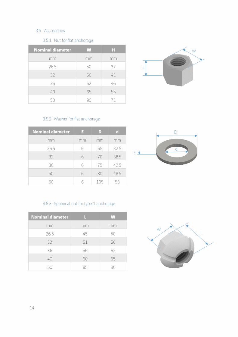
3.5.4. Spherical nut for type 2 anchorage
3.5.5. Spherical washer for type 2 anchorage
3.5.6. Bearing plate for flat and type 2 anchorage
3.5.7. Spherical plate for type 1 anchorage
The hole of this plate is conical
Dimensions Unit Nominal bar diameter (mm)
26.5 32 36 40 50
L mm 34.46 38.27 45.96 55.18 70.31
W mm 31 36 41 45 57
Dimensions Unit Nominal bar diameter (mm)
26.5 32 36 40 50
D mm 75 80 90 95 125
E mm 10 10 10 10 15
Dimensions Unit Nominal bar diameter (mm)
26.5 32 36 40 50
L mm 125 125 160 160 200
l mm 110 125 140 160 200
E mm 35 35 40 40 45
Dimensions Unit Nominal bar diameter (mm)
26.5 32 36 40 50
L mm 125 125 160 160 200
l mm 110 125 140 160 200
E mm 35 35 40 40 45
L
l
L
E
D
E
L
E
l

16
3.5.8. Bearing plate for flat and type 2 anchorage for injection
3.5.9. Spherical plate for type 1 anchorage for injection
3.5.10. Bearing plate for flat and type 2 anchorage for injection + tube
3.5.11. Spherical plate for type 1 anchorage for injection + tube
Dimensions Unit Nominal bar diameter (mm)
26.5 32 36 40 50
L mm 160 160 160 160 190
l mm 115 125 140 160 190
E mm 40 40 40 40 60
X mm 90 90 105 105 142
A mm 10 10 10 10 12
Dimensions Unit Nominal bar diameter (mm)
26.5 32 36 40 50
L mm 160 160 160 160 190
l mm 115 125 140 160 190
E mm 40 40 40 40 60
X mm 90 90 105 105 145
Dimensions Unit Nominal bar diameter (mm)
26.5 32 36 40 50
L mm 125 125 160 160 200
l mm 110 125 140 160 200
E mm 35 35 40 40 45
X mm 90 90 105 105 145
Ø x e mm 42,5x2 48,5x2 50,8x2 57,5x2 76,1x2
Dimensions Unit Nominal bar diameter (mm)
26.5 32 36 40 50
L mm 160 160 160 160 190
l mm 115 125 140 160 190
E mm 40 40 40 40 60
X mm 90 90 105 105 145
Ø x e mm 42,5x2 48,5x2 50,8x2 57,5x2 76,1x2
L l
E
A
X
L l
E X
l
L
X
E
200 to 250
Ø x e
L
l
E
Ø x e X
200 to 250

17
3.5.12. Coupler
Bars L D
26.5 90 45
32 115 50
36 130 60
40 140 65
50 170 76
3.5.13. Caps
Long plastic cap
Bars L H X Dint
26.5 110 205 90 92
32 110 205 90 92
36 130 205 105 111
40 130 205 105 111
50 165 300 145 145.4 Polyamide fiber (30%) + anti UV additive fixed with 4 x M8x20 (upto D40) and M8x60 (for D50) zinc-plated screws
Short Freyssibar plastic cap
Bars L H X Dint
26.5 110 80 90 92
32 110 80 90 92
36 130 100 105 111
40 130 100 105 111
50 165 115 145 145.4 Polyamide fiber (30%) + anti UV additive fixed with 4 x M8x20 (upto D40) and M8x60 (for D50) zinc-plated screws Freyssibar plastic cap seal
Bars D e
26.5 95 3.5
32 95 3.5
36 114 3.5
40 114 3.5
50 149 3.5 Nitrile
L
D
D
L
H
X
Dint
L
H
X
Dint
d

18
Short Freyssibar steel cap
Bars L H X Dint
26.5 110 81 90 99.5
32 110 81 90 99.5
36 140 126 105 111
40 140 126 105 111
50 185 136 142 137 These caps can be hot galvanized or spray metalized upon request
Long Freyssibar steel cap
Bars L H X Dint
26.5 110 196 90 99.5
32 110 196 90 99.5
36 140 206 105 111
40 140 206 105 111
50 185 266 142 137 These caps can be hot galvanized or spray metalized upon request Freyssibar steel cap steel
Bars L E X
26.5 110 3 90
32 110 3 90
36 140 3 105
40 140 3 105
50 185 3 142 Plastic plug ½”
Bars D M H
26.5 31.5 12 22
32 31.5 12 22
36 31.5 12 22
40 31.5 12 22
50 31.5 12 22
L
H
X
Dint
L
H
X
D
L
X
E
H
D
M

19
3.5.14. Sheath
They are used to isolate, guide and protect tensile elements on a bridge for example. They can be made of steel corrugated sheath, plastic tubes or steel pipes. Connecting accessories may be sealed by plastic adhesives, heat-shrink sleeves or mastics.
* Theoretical volume without losses
Item Dimensions Unit Nominal bar diameter (mm)
26.5 32 36 40 50
Steel corrugated sheath Internal diameter mm 45 50 55 60 75
Thickness mm 0.45 0.45 0.45 0.45 0.50
Volume of grout* L/m 1.0 1.2 1.4 1.6 2.5
Connection element (internal
diameter)
mm 50 55 65 70 85
HDPE Tube
External diameter mm 63 63 75 75 90
Thickness mm 5.8 5.8 6.8 6.8 8.2
Volume of grout* L/m 1.5 1.3 1.9 1.7 2.3
Steel Pipe
External diameter mm 51 57 60.3 70 76.1
Thickness mm 2.6 2.6 2.9 2.9 2.9
Volume of grout* L/m 1.1 1.3 1.3 2.0 1.9
Steel duct for movable coupling (see 3.4.1)
External diameter mm 70 76.2 88.9 95 114.3
Thickness mm 2 2 2 2 2
Minimum length (L = sleeve)
mm 180+L 205+L 220+L 230+L 260+L
Steel duct for fixed coupling (see 3.4.2)
External diameter mm 88.9 88.9 101.6 114.3 152.4
Thickness mm 2 2 2 2 2
Length mm 210 235 255 265 320

20
3.5.15. Injection accessories
For caps:
For vent on duct : For vent on anchorage :
Short or long cap
Silicon paste
Plastic valve
Injection pipe d = 18mm
Silicon paste
½ ‘’ connector
Plastic plug
Injection half shell
Duct
Injection pipe d = 18mm
Silicon paste
Valve Injection pipe d = 18mm
Anchorage
½ ‘’ connector

21
3.6. Corrosion protection
Several types of corrosion protection are proposed as standard solutions: the choice depends of the environment conditions and installation procedure.
3.6.1. Grout
The injection work is done on site.
Adjusting the position + adhesive tape
Watertighness
Duct
Tensioning
Mounting cap with 4 screws
Extra-length cut after stressing

22
3.6.2. Wax
A flexible and stable product based on microcrystalline wax and specific additives, intended to protect the prestressing steels. At room temperature (20/25 ° C), it has a pasty – spinning appearance. Must be injected at a temperature of approximately 100 ° C to ensure reliable and rapid injection. The bar is generally prefabricated before installation.
Installation :
Reinforcement - formwork - concreting
Melting point °C
NFT 60-121
Penetration at 25 °C
NFT 60-119
Density at 25°C (Pycnometer)
Solubility in water
(water jet) Salt spray
Corrosion against copper
ASTM D130
65 – 75 65 – 115 880 Insoluble > 41 1a (no corrosion)
Fixing the plate with 4 screws
Freyssibar Nut
Adjustment of the position + strip
Welded Anchor
PEHD DUCT
Wax
Freyssibar
23
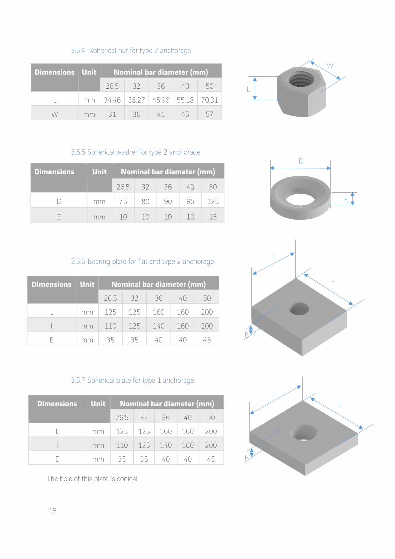
Stressing – cap filling – cap fixing
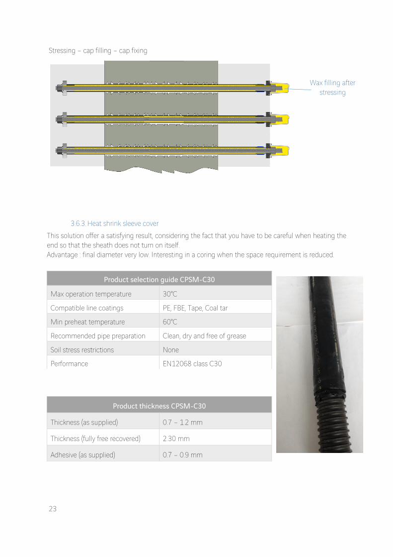
3.6.3. Heat shrink sleeve cover
This solution offer a satisfying result, considering the fact that you have to be careful when heating the end so that the sheath does not turn on itself. Advantage : final diameter very low. Interesting in a coring when the space requirement is reduced.
Product selection guide CPSM-C30
Max operation temperature 30°C
Compatible line coatings PE, FBE, Tape, Coal tar
Min preheat temperature 60°C
Recommended pipe preparation Clean, dry and free of grease
Soil stress restrictions None
Performance EN12068 class C30
Product thickness CPSM-C30
Thickness (as supplied) 0.7 – 1.2 mm
Thickness (fully free recovered) 2.30 mm
Adhesive (as supplied) 0.7 – 0.9 mm
Wax filling after stressing

24
3.6.4. Galvanization
To realize the galvanization, Freyssinet are proceeding the following steps for each bars :
degreasing of the bars in an alkaline bath
cleaning / washing so as to remove all degreasing products
chemical application of a corrosion inhibitor Denso Holdtight, sprayed at high pressure so as to force the chemical into microstructure
Blasting
Fluxing
Submerging in the zinc kettle at a controlled temperature of +- 435°C The galvanization process respects the ISO 1461 standard.
3.6.5. Denso
The Denso-green is a petroleum-based anti-corrosion strip applicable at low temperature according to EN 12068. It consists of a 1.1mm thick non-woven polypropylene support impregnated on both sides with a protective petrolatum mastic. It is stabilized by polymer and mineral additives and can be used at service temperatures between -50 ° C (58 ° F) and + 50 ° C (122 ° F). This strip is used in many applications:
Anti-corrosion protection of metal structures in buildings and aerial installations
Corrosion protection of metal parts or pipes located in concrete or cement screeds (Freyssibar’s case)
Separation layer between metallic materials of different composition (galvanic couple)
Product properties CPSM-C30
Property Test Method Typical value
Tensile strength ISO R527 20 Mpa
Elongation ISO R527 580%
Hardness, shore D ASTM D-2240 55
Shrink force ASTM D-638 150°C 40 psi

25
3.7. Marking
3.7.1. Bars
Each bundle of bars is identified with a steel label containing:
Freyssinet Company Name
Size : “Freyssibar” nominal diameter
Length
Steel grade
Bundle number
Batch number
Purchase order
Weight : net and gross
Quantity of bars
3.7.2. Accessories
Each coupler, washer and nut shall be marked in areas that do not impair the performance of the anchorage with “RYC”, the reference of the component and the diameter, and the accessories batch number. Marking shall be done according to fabrication drawings with additional indications if any specific.
Temporary sealing of leaks in low-pressure gas lines Properties Units Value
Value referring to a standard
Testing
Color - Brown-Green - -
Material - Nonwoven
polypropylene - -
Dielectric strength kV / mm ≥ 9 - -
Dielectric strength Ω m² ≥ 10 ¹⁰ ≥ 10 ⁶ EN 12068
Resistance to tearing N / cm ≥ 60 EN 12068
Elongation at break % ≥ 7 - DIN 30672
Drop Point °C (°F) +60 (+140) - -
Saponification Index mg KOH / g ≤ 0.25 <25 EN 12068
Operating temperature °C
(°F)
-50 to + 30
(-58 to +86) - -

26
4. DESIGN
4.1. Calculation
The design of the system complies with ETAG 013 and the design of the bar comply with ASQPE and prEN10138.
4.2. Testing
According to the ASQPE regulation :
Fatigue resistance under axial force,
Isothermal relaxation,
Stress corrosion test in distilled water All these tests take place at accredited laboratories COFRAC or equivalent EA (European Accreditation)
4.3. Type of use
Code Standard Fp factor Fpk factor
A Post-Tensioned Structures Eurocode 0.9 Fp 0.1% 0.8 Fpk (lower)
B Re-Use / /
0.60 Fpk 1st use
0.50 Fpk for subsequent uses
The maximum allowable stressing force in the prestressing bars is given by the relevant design standards which can be different than this table. Recommendations are given below as examples. (Note : Fpk means the guaranteed tendon tensile breaking load and Fp0.1% means the proof load).
4.4. Choice of the adapted solution
In order to design a Freyssibar adapted to your situation, FPC need some information. These input data are very important and will impact directly the price. The designer of the structure gives all information used for the design. FPC can do some hypothesis which can be conservative. You have to know which category of prestressing you will use, in which type of structure the bars will be placed, and which option do you want. A recapitulative table has been made for you, in order to help you choose the right product adapted to your situation. First, you have to choose which type of prestressing you need. Then, check the remain possibilities, and select in which structure the Freyssibar will fit. It further restricts your possibilities. Then the last choice is about the option that you want: do you want it waterproof? Replaceable? Follow the resulting line and discover which product is perfectly adapted to your situation.

27
External Internal non adhesive Internal adhesive Select your type of
prestressing
Concrete Select the structure
Metallic
Masonry
Wood
Re-Tensionable Select the w
anted functionalities
Replaceable
External anchorage
CE Marking
Short plastic
Short plastic
Short plastic
Short plastic
No cap
No cap
Short plastic
Short plastic
Short plastic
Short plastic
No cap
No cap
Short plastic
Short plastic
Cap
Passive Anchorage
All types
Flat with
washer
All types
Flat with
washer
Flat welded
nut
Flat welded
nut + w
asher
All types
Flat with
washer
All types
Flat with
washer
Flat welded
nut
Flat welded
nut + w
asher
All types
Flat with
washer
Type
Short plastic
Short plastic
Long plastic
Long plastic
No cap
No cap
Long plastic
Long plastic
Long plastic
Long plastic
No cap
No cap
Short plastic
Short plastic
Cap
Active Anchorage
All types
Flat with
washer
All types
Flat with
washer
All types
Flat with
washer
All types
Flat with
washer
All types
Flat with
washer
Flat with
washer
Flat nut +
washer +
vent
All types
Flat nut +
washer
Type
HD
PE Steel pipe
HD
PE Steel pipe
HD
PE Steel pipe
HD
PE Steel pipe
All types
All types
All types
All types
All types
All types
Steel corrugated
Steel corrugated
Steel corrugated
Steel corrugated
Duct
Wrapping, G
alvanization, H
eat Shrink
Wrapping, G
alvanization, H
eat Shrink
Wrapping, G
alvanization, H
eat Shrink
Wrapping, G
alvanization, H
eat Shrink
Wrapping, G
alvanization,
Heat Shrink
Wrapping, G
alvanization, H
eat Shrink
Wrapping, G
alvanization,
Heat Shrink
Wrapping, G
alvanization, H
eat Shrink
Wrapping, G
alvanization, H
eat Shrink
Wrapping, G
alvanization, H
eat Shrink
- - - -
Short term
Corrosion protection
Wax
Grout
Wax
Grout
Wax
Wax
Wax
Wax
Wax
Wax
Wax
Wax
Grout
Grout
Grout
Grout
Long term

28
4.5. Warranty
1. Scope of Warranty • Supplier warrants that the Goods supplied to the beneficiary of this Warranty are manufactured in compliance with the applicable technical specifications. • Supplier agrees to indemnify the Warrantee from any direct damages, costs, losses or expenses arising from any error or default in design of the Goods, and/or fault or deficiency in materials or workmanship provided as part of the Goods (“Defect”). • In the event the Warrantee notifies the Supplier of any Defect within: - Two (2) years for all steel and plastic components and for corrosion protection; following delivery of the Goods to the Warrantee according to applicable Incoterms, the Supplier shall carry out correction work in respect of such Defects in accordance with the provisions below: - Liability of the Supplier under this Warranty is limited to repair or delivery of replacement Goods at the applicable delivery point, at the Supplier’s option; - For all components supplied as part of the Goods, Supplier's Warranty shall apply to any repaired or replaced Goods, for an extended period of one (1) year following completion of repair or delivery of replacement Goods, not to exceed an overall Warranty period of three (3) years - 2. Exclusions Notwithstanding the foregoing, the Supplier shall not be liable for Goods' failure to comply with the Warranty in any of the following events: • The Defect arises because the Warrantee failed to follow the Supplier's oral or written instructions as to the storage, commissioning, installation, use and maintenance of the Goods as provided in the manuals listed below; • The Defect arises as a result of any error or omission of any drawing, design or specification supplied by the Warrantee to the Supplier; • The Warrantee materially alters or repairs the Goods without the Supplier’s prior written consent; • The Defect arises as a result of normal wear and tear (including corrosion of steel parts and ageing of plastic components), wilful damage, negligence or abnormal storage or working conditions or any misuse of the Goods, including in particular damage resulting from rough handling; • The Defect arises from the occurrence of any Force Majeure event, Act of God, fire, and other circumstances beyond the Supplier’s reasonable control; • The Defect arises from an exposure at an outside temperature above 50°C; • The Defect arises from overloads, stresses, impacts, sliding movements and any other parameter exceeding data provided in the applicable technical specifications. It is further understood that Supplier shall bear no liability for: • Any consequential damages incurred by the Warrantee and/or its clients (including but not limited to costs for third party inspection, liquidated damages, penalties for delay, loss of use, stand-by costs, etc.) or aesthetic damages; and • Any dismantling or reinstatement costs; • Warrantee’s or third party’s labour costs; • Specialist equipment, scaffolding, heavy tools and lifting equipment as well as power and water needed for any correction work.

29
3. Warrantee’s duties The Warrantee shall follow the instructions provided in the installations and maintenance manuals (in their latest versions) THIS WARRANTY SHALL BE APPLICABLE AS THE STANDARD WARRANTY RELATING TO ANY OF THE GOODS SOLD BY THE SUPPLIER TO THE WARRANTEE. TO THE EXTENT PERMITTED BY LAW, THIS WARRANTY EMBODIES THE ENTIRE UNDERSTANDING OF THE SUPPLIER AND THE WARRANTEE, AND SUPERSEDES ANY PRIOR WRITTEN OR OTHER AGREEMENT BETWEEN THE SUPPLIER AND THE WARANTEE, IN RELATION TO ANY WARRANTY RELATING TO THE GOODS.

30
5. MANUFACTURING & LOGISTICS
FPC coordinates all the steps of the projects. Support departments are also involved in the process:
5.1. Resources
The structural fittings division consists of a team with:
Division manager
Technical and sales engineers
Technical experts
Design engineers
Draftsmen
The detailed organigram can be given on demand.
Marketing
Industrialization
Production
Transit & Logistic
Structural fittings
Conception & testing
Purchase &
supply Control

31
5.2. Manufacturing
5.2.1. Site of production & distribution
The bars and anchorage are manufactured in South Africa. Then, the bars are stored and transformed to become prefabricated bars at Freyssibar Center, in France. A detailed presentation of those several sites is available on request.
5.2.2. Manufacturing process
5.2.2.1. Bars incoming inspection
The bars are received from Arcelor Mittal South Africa in bundles of 2T. Full inspection is done per delivery including:
Chemical composition and mechanical properties check as per raw material certificates
Quantities inspection
Dimensional check of raw diameters
Traceability record
The acceptance of the material is based on the compliance of this criteria according to raw material specifications.

32
5.2.2.2. Bars preparation
The bars are prepared before thread rolling. This preparation consists of:
A shot blasting operation with the aim to remove the mill scale off the bars.
A peeling operation of the ends of the bars to facilitate the entrance of the bars into
the thread rolling machine.
5.2.2.3. Thread rolling
In order to put a thread on the material, the bars are cold formed: going through a thread rolling machine, the tooling deforms the material progressively to give the bars their final thread shapes. The full length goes through the machine and becomes fully threaded. Every single bar is then visually inspected and dimensionally controlled and recorded.

33
5.2.2.4. Stretching
After thread rolling process, every single bar goes through a stretching equipment. This machine grabs the bars at the end and pulls them from one side to a pre-determined load. This operation allows the material to increase the Yield point above the minimum required by the grade 835/1030. It therefore gives the bars their final mechanical properties.
Every bars that gets pulled is fully documented and saved with a graph that shows the load and the elongation which was recorded during the stretching operation.
5.2.2.5. Cutting/packing
Final the full length bars are cut and packed according to the customer requirements and Freyssinet specifications.
5.2.2.6. Tensile testing
As per Freyssinet specifications and the requirements of prEN10138, one bar is tensile tested every 15T of steel manufactured per cast per diameter. This mechanical properties verification is performed internally at Rand York Castings according to the required testing standards. Tensile test certificates are issued and accompany the quality documentation that goes out with every shipment
0
100
200
300
400
500
600
700
800
900
0 100 200 300
Forc
e (
kN)
Elongation (mm)

34
5.3. QSE
The quality assurance system in force in the factory supplying the ground anchors units shall comply with, or be equivalent to, the standard ISO 9001: 2008.
5.3.1. Quality - ISO 9001
FPC is certified since September 1997 (according to successive standards as ISO 9002 v94 and ISO 9001 v2000). Since the renewal audit of September 2009, the company is certified ISO 9001 v2008. Manufacturing, sale and trade of structure equipment (road expansion joints, bearings and seismic protection devices) and components for cable stays and concrete prestressing. Trade of products for structure reinforcement.
5.3.2. Safety - OHSAS 18001
FPC is certified OHSAS 18001 v 2007 since April 2011.
5.3.3. Environment – ISO 14001
FPC is certified ISO 14001 since October 2010

35
5.4. Quality documentation
Different levels of quality documentation can be proposed (from level 0 to level 2). The definition of each level is available on the quality file price list sent with the offer. The level of the quality documentation has to be determined at the beginning of the project.
Item Documentation Level 0 Level 1 Level 2
General Documentation
Delivery note X X X
Bar
Material certificate 3.1 + testing report
- X X
ITP - - X
Nut
Material certificate 3.1 - X X
ITP - - X
Washer
Material certificate 3.1 - X X
ITP - - X
Coupler Material certificate 3.1 - X X
ITP - - X
Plate
Material certificate 3.1 - X X
ITP - - X
*All documents can be shown during an audit.

36
6. REFERENCE
The references list is available on request for all FPC projects.