Embed Size (px)
Citation preview

Max Machinery, Inc. 210 Series User Manual © Copyright 2013 Rev. 002Q4 1
210 Piston Series Positive Displacement Flow Meters
Model
Model
Model
Model
Model
Positive Displacement Flowmeters
Operational Manual
For ModelsModel 213, P002, 214, 215 and 216
Max Machinery, Inc. 210 Series User Manual © Copyright 2013 Rev. 002Q4 2
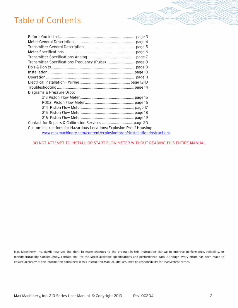
Table of Contents
Max Machinery, Inc. (MMI) reserves the right to make changes to the product in this Instruction Manual to improve performance, reliability, or
manufacturability. Consequently, contact MMI for the latest available specifications and performance data. Although every effort has been made to
ensure accuracy of the information contained in this Instruction Manual, MMI assumes no responsibility for inadvertent errors.
Before You Install .................................................................................. page 3 Meter General Description .................................................................. page 4 Transmitter General Description ....................................................... page 5 Meter Specifications ............................................................................ page 6 Transmitter Specifications Analog ................................................... page 7 Transmitter Specifications Frequency (Pulse) ...............................page 8 Do’s & Don’ts .......................................................................................... page 9 Installation .............................................................................................page 10 Operation ................................................................................................ page 11 Electrical Installation - Wiring ...................................................... page 12-13 Troubleshooting ...................................................................................page 14 Diagrams & Pressure Drop: 213 Piston Flow Meter ..........................................................page 15 P002 Piston Flow Meter .....................................................page 16 214 Piston Flow Meter ......................................................... page 17 215 Piston Flow Meter .........................................................page 18 216 Piston Flow Meter .........................................................page 19 Contact for Repairs & Calibration Services ..................................page 20 Custom Instructions for Hazardous Locations/Explosion Proof Housing: www.maxmachinery.com/content/explosion-proof-installation-instructions
DO NOT ATTEMPT TO INSTALL OR START FLOW METER WITHOUT READING THIS ENTIRE MANUAL
Max Machinery, Inc. 210 Series User Manual © Copyright 2013 Rev. 002Q4 3
Before You Install
Thank you for choosing to install a Max Machinery precision flow meter. To ensure the best experience please take a moment to read through this manual prior to installation.
When you purchased this meter a flow engineer helped determine many of the factors that will be reviewed on the following pages. You may find it useful to fill out the form below and keep it in your files for reference.
When you are ready to install there will be a few tools you will need:
Meter Installation: The meter and transmitter A signal cable (available from factory) The display or signal processing device Indicator Manual Calibration Certificate Bypass plumbing supplies
Many Max meters are installed and operate for decades, so having the following information in your records may prove useful. We have provided this outline as a starting point.
Process Temperatures ___________________________ Fluid Viscosity ____________________________________
Operating Range ________________________________ Line Pressure ____________________________________
Max Sales # or PO # _____________________________ Installation Date __________________________________
Meter Model # __________________________________ Meter Serial # ____________________________________
Transmitter Model # _____________________________ Transmitter Serial # _______________________________
Notes: _____________________________________________________________________________________________
_____________________________________________________________________________________________
_____________________________________________________________________________________________
_____________________________________________________________________________________________

Max Machinery, Inc. 210 Series User Manual © Copyright 2013 Rev. 002Q4 4
Meter General Description
The Max 210 Series Flow Meters are positive displacement piston type units capable of great accuracy over a wide range of flow rates and fluid viscosities. The four basic sizes of this series (213, 214, 215, 216) will measure flows from 1 cc/min to 25 gal/min. Various “O” ring and internal plating options are available to meet temperature and fluid compatibility requirements.
In a piston type flow meter, four pistons and cylinders are arranged in a radial fashion around a central crankshaft. Two fluid ports on the cylinder wall, a port at the top of the cylinder, and a grooved piston enable fluid entering the flow meter’s central cavity to be measured and pumped out by each piston in turn. The valving action for each cylinder is accomplished by the piston adjacent to it. The accuracy of a piston flow meter is dependent on close tolerances in the cylinder wall and piston. Max Machinery regularly holds tolerances as fine as 0.00005 inches in the production of these meters.
The movement of the pistons is converted to a circular motion at the central crankshaft, which is coupled to a magnet in the flow meter. This motion is sensed by an external electronic transmitter, which converts flow into a voltage, pulse train, or current for further processing.
The Max Series 210 Meter can be expected to perform superbly if operated within the confines of its design envelope. For this reason, it is important to read this manual and understand the operational requirements and limits of the meter. Our Technical Service staff will be happy to answer any questions that this manual does not cover.
inlet outlet
over 100 data points per rotation
Max Model 214
Max Machinery, Inc. 210 Series User Manual © Copyright 2013 Rev. 002Q4 5
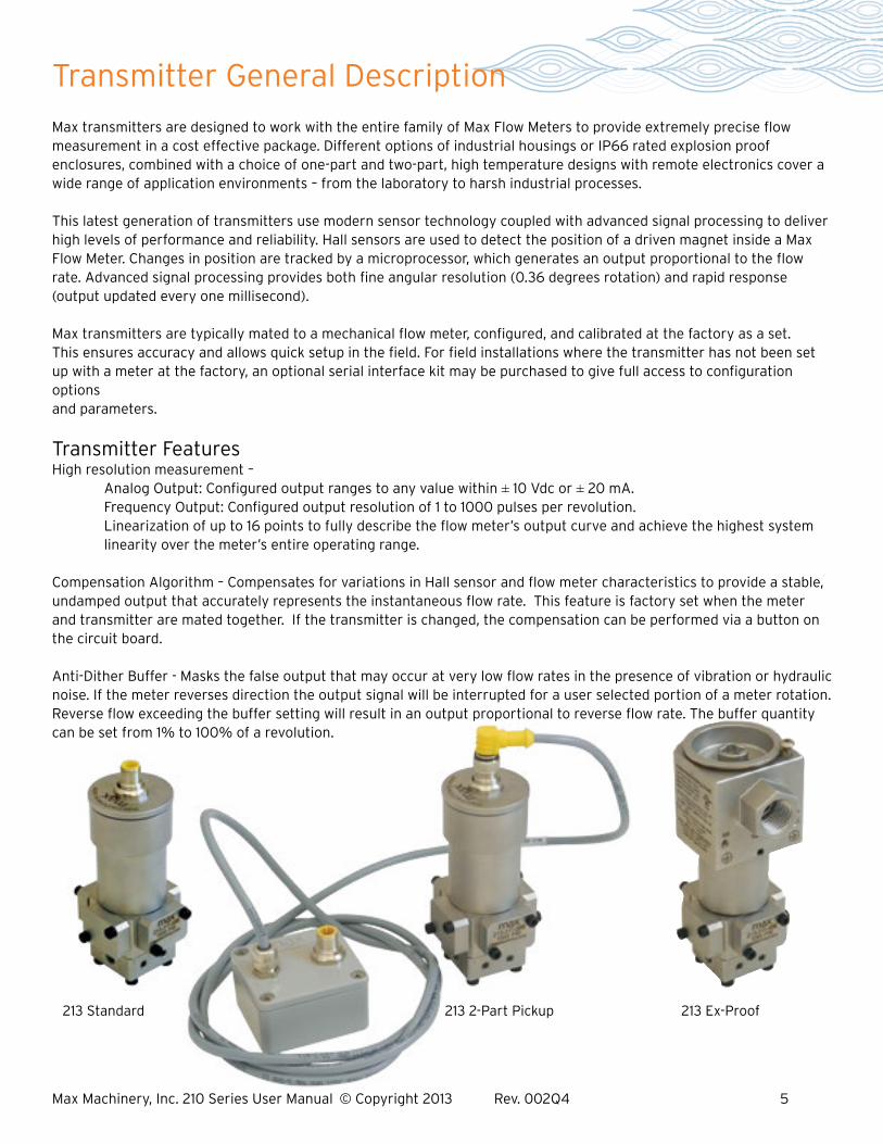
Transmitter General Description
Max transmitters are designed to work with the entire family of Max Flow Meters to provide extremely precise flow measurement in a cost effective package. Different options of industrial housings or IP66 rated explosion proof enclosures, combined with a choice of one-part and two-part, high temperature designs with remote electronics cover a wide range of application environments – from the laboratory to harsh industrial processes.
This latest generation of transmitters use modern sensor technology coupled with advanced signal processing to deliver high levels of performance and reliability. Hall sensors are used to detect the position of a driven magnet inside a Max Flow Meter. Changes in position are tracked by a microprocessor, which generates an output proportional to the flow rate. Advanced signal processing provides both fine angular resolution (0.36 degrees rotation) and rapid response (output updated every one millisecond).
Max transmitters are typically mated to a mechanical flow meter, configured, and calibrated at the factory as a set. This ensures accuracy and allows quick setup in the field. For field installations where the transmitter has not been set up with a meter at the factory, an optional serial interface kit may be purchased to give full access to configuration options and parameters.
Transmitter Features High resolution measurement – Analog Output: Configured output ranges to any value within ± 10 Vdc or ± 20 mA. Frequency Output: Configured output resolution of 1 to 1000 pulses per revolution. Linearization of up to 16 points to fully describe the flow meter’s output curve and achieve the highest system linearity over the meter’s entire operating range.
Compensation Algorithm – Compensates for variations in Hall sensor and flow meter characteristics to provide a stable, undamped output that accurately represents the instantaneous flow rate. This feature is factory set when the meter and transmitter are mated together. If the transmitter is changed, the compensation can be performed via a button on the circuit board.
Anti-Dither Buffer - Masks the false output that may occur at very low flow rates in the presence of vibration or hydraulic noise. If the meter reverses direction the output signal will be interrupted for a user selected portion of a meter rotation. Reverse flow exceeding the buffer setting will result in an output proportional to reverse flow rate. The buffer quantity can be set from 1% to 100% of a revolution.
213 Standard 213 2-Part Pickup 213 Ex-Proof

Max Machinery, Inc. 210 Series User Manual © Copyright 2013 Rev. 002Q4 6
Meter Specifications
Model 213 P002 214 215 216 1 Maximum flow rate Gal/min: 0.48 0.53 2.64 9.25 26.4 Liters/min: 1.8 2.0 10 35 100 Maximum pressure (psi) 2xx-3xx, 2xx-4xx: 1,000 psi (70 bar) 2xx-6xx: 3,000 psi (210 bar) P002, 214-5xx 7,250 psi (500 bar) Pressure drop (PSIG) Operating maximum: 15 15 28 30 30 Absolute maximum: 20 20 30 42 42 100% Flow (3cps): 3.25 3.25 3.5 5 9 2 Maximum temperature --------------------- 1 part: 195°F (90°C) -------------------- 2 Maximum temperature -------------------- 2 part: 435°F (225°C) -------------------- 3 Recommended filtration 10 micron 10 micron 10 micron 10 micron 10 micron Displacement (cc/rev) 0.887 1.0 10.5 47.6 169.5 Weight (lbs) 1000 & 3000 psi 1.25 (0.57Kg) --- 6.25 (2.8Kg) 22.75 (10.3Kg) 55.25 (25.1Kg) 7250 psi --- 4.2 (1.9kg) 14.4 (6.5) --- --- Typical k-factor (pulses/cc) 290 Frequency series Transmitter 1000 1000 90 20 5 Port size (NPT): 0.125” --- 0.375” 0.500” 0.750” SAE #4 #4 #6 #12 #18 1 For viscosities of 30 cps or more, derate per pressure drop curves for higher viscosities.2 Dependent on meter seal material, transmitter model, orientation and ambient temperature. See transmitter manual; consult factory.3 Some materials may have different filter requirements, consult factory.

Max Machinery, Inc. 210 Series User Manual © Copyright 2013 Rev. 002Q4 7
Transmitter Specifications AnalogSupply Voltage 12 Vdc (Models 29X-XXX-100) 24 Vdc (Models 29X-XXX-000)
Supply Current 90 mA max@ 12 Vdc, 45 mA max@ 24 Vdc
Short Circuit Current 21 mA 1 Output Update Rate 1 ms
Resolution Adjustable without recalibration to any range of ± 10 Vdc Model 29X-3XX-XXX or ± 20 mA Model 29X-2XX-XXX
Ambient Temperature Range Transmitter (Storage)–40ºC to 85ºC (–40ºF to 185ºF) 2 Transmitter (Operation)–40ºC to 80ºC (–40ºF to 175ºF)
Maximum Temperature, Process Fluid (see technical for explosion proof models)(20ºC Ambient, 5V supply) Standard Model 90ºC (195°F) – Models 295 & 296 High Temp Model – Model 296 Ultra-High Temp Model 225ºC (435°F) – Models 295 & 296
Anti-dither Range Software selectable from 1-100% of 1 revolution. 50% of a meter revolution - unidirectional 2% bidirectional are typical default settings
Signal Filtering Software selectable from 1 ms to 64 sec. time constant
1 Full step change is subject to signal damping2 Temperature of metered fluid will affect transmitter temperature, see graph below
Model 29X Transmitter Series
-250
50
20
40
60
80
100
120
100 150 200 250 300
Process Temperature °C
Am
bie
nt
Tem
per
atu
re °
C
225
110
Ultra High temperature 2 part pickup
Standard High temperature 2 part pickup
295 & 296 296 295 & 296
Max Machinery, Inc. 210 Series User Manual © Copyright 2013 Rev. 002Q4 8
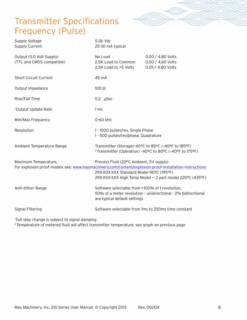
Supply Voltage 5-26 Vdc Supply Current 25-30 mA typical
Output (5.0 Volt Supply) No Load 0.00 / 4.80 Volts(TTL and CMOS compatible) 2.5K Load to Common 0.00 / 4.60 Volts 2.5K Load to +5 Volts 0.25 / 4.80 Volts
Short Circuit Current 45 mA Output Impedance 100 Ω
Rise/Fall Time 0.2 μSec
1 Output Update Rate 1 ms
Min/Max Frequency 0-60 kHz
Resolution 1 - 1000 pulses/rev, Single Phase 1 - 500 pulses/rev/phase, Quadrature
Ambient Temperature Range Transmitter (Storage)–40ºC to 85ºC (–40ºF to 185ºF) 2 Transmitter (Operation) –40ºC to 80ºC (–40ºF to 175ºF)
Maximum Temperature, Process Fluid (20ºC Ambient, 5V supply) For explosion proof models see: www.maxmachinery.com/content/explosion-proof-installation-instructions 29X-X0X-XXX Standard Model 90ºC (195°F) 29X-X5X-XXX High Temp Model — 2 part model 225ºC (435°F)
Anti-dither Range Software selectable from 1-100% of 1 revolution. 50% of a meter revolution - unidirectional - 2% bidirectional are typical default settings Signal Filtering Software selectable from 1ms to 250ms time constant
1 Full step change is subject to signal damping2 Temperature of metered fluid will affect transmitter temperature, see graph on previous page
Transmitter Specifications Frequency (Pulse)
Max Machinery, Inc. 210 Series User Manual © Copyright 2013 Rev. 002Q4 9
DO: Install bypass plumbing around the flow meter. This is useful during start up for removing dirt and air from the plumbing or when measuring fluid that may freeze inside the line and need to be remelted before it can pass through the meter. It also allows removing the flow meter for service without disabling the system.DO: Be very careful to keep parts clean during installation or teardown. A little dirt can look like a truckload compared to the 10 micron filtration requirement for series 210 Meters.DO: Clean the filter on a regular basis.
DON’T: Run water or aqueous solutions not approved by Max through your flow meter because of internal galling.DON’T: Steam clean the meter (bypass or remove the meter if necessary).DON’T: Blow down the meter with compressed air or gas because it may over-speed and damage the meter.DON’T: Remove the Transmitter from the flow meter body. The transmitter is phased to the meter and a measurement error will result. Re-calibration will be necessary; see the transmitter interface software manual.DON’T: Disassemble the flow meter. These are precision devices which require special tools and techniques.DON’T: Turn on the pump in a system filled with material that is solid at room temperature. Wait until the material is completely melted and use the flow meter bypass valve during start up.DON’T: Apply excessive differential pressure across the flow meter as it will cause internal failure (see the pressure drop curves for safe area operation).DON’T: Over pressurize the meter. Maximum pressure is either 1,000 PSI (70 bar) 3,000 PSI (210 bar) or 7250 PSI (500 bar) depending on model purchased. DON’T: Exceed the maximum flow rates for the material viscosity.DON’T: Allow materials which solidify in air to set up in the flow meter. These may be impossible to remove. If the meter needs to be removed for repair and cannot be completely cleaned. Plug the inlet and outlet ports at once.
Do’s & Don’ts

Max Machinery, Inc. 210 Series User Manual © Copyright 2013 Rev. 002Q4 10
Installation
For optimum performance, install the flow meter in one of the configurations shown below. The following items and conditions should be considered:
Line and Bypass Valves: These valves allow filter cleaning or flow meter removal without completely shutting the system down and draining the lines. They also allow system start up under conditions which could damage the meter; such as: air in the lines, high temperature materials, or initial line surges.
Filtration: Clearances between the flow meter piston and cylinder wall are typically 0.0002” to 0.0004”. Any dirt present in the system can jam or damage the unit. A 10 micron filter (such as a Max 381 Series stainless steel unit) is generally recommended, although materials with very high viscosities may require a coarser filter. For bidirectional flow applications, use a filter on each side of the flow meter. Materials with fibrous or non abrasive particulate matter may have to be run without filters. Follow the recommendation of your Max Sales Engineer or consult our Technical Service Department.
Inlet and Outlet Ports: Use the “IN” port as the inlet for the most predominant flow direction. Install the flow meter on the discharge side of the pump whenever possible. Excessive vibration at the meter should be avoided.
High Temperatures: Use the “Vertical Installation” drawing. This minimizes heat transfer by convection from the flow meter to the transmitter. The transmitter is the most heat sensitive element in the system and the transmitter manual should be consulted for specific limits. An optional fluid heater block can be used on the flow meter to keep it at operating temperature during standby conditions. For substances that are solid at room temperature, the block may be required to keep the material molten and flowing through the meter.
Clean Plumbing: Before installing the flow meter, clean the inside of the pipe line with compressed air or steam (especially when using new pipe). Don’t use water, steam, or compressed air on the meter itself!
Piping Diagram
FILTER
VALVE 2VALVE 1
FLOW METER
VALVE 3
FLOW
BYPASS
FILTER FILTER
VALVE 2VALVE 1
FLOW METER
VALVE 3
FLOW
BYPASS
FILTER
VALVE 1
VALVE 2
FLOW METER
VALVE 3
FLOW
BYPASS
Horizontal Installation
Horizontal Two-Way Flow
Vertical Installation

Max Machinery, Inc. 210 Series User Manual © Copyright 2013 Rev. 002Q4 11
Determine that the following parameters of your flow metering system are within the specifications for the specific 210 Series Meter being used: Maximum System Pressure (Specifications) Differential Pressure across meter (Pressure Drop Curves) Maximum Flow Rate (Pressure Drop Curves) Metered Fluid Temperature (Sales specification, transmitter specifications page 7)
If the metered fluid is greater than 80°F (28°C) over ambient, see the “High Temperature Start Up” section below.
With valves (#1) and (#2) closed, slowly open valve (#3) (bypass) to clear the lines of foreign particles and air.Slowly open the inlet valve (#1). Slowly open the outlet valve (#2). Completely close the bypass valve.
No routine maintenance, cleaning, or lubrication of the flow meter is required. A routine filter cleaning schedule should be established. The system should be shut down if abnormal noises occur or if unusual differential pressures across the meter are encountered.
High Temperature Start Up: For fluids above 150°F (82°C) based on 70°F ambient, a special procedure is required to prevent thermal shock and permanent damage to the flow meter. The warm up time is determined by the equation below:
TIME (minutes) = connector size (inches) x (operating temperature (°F)-125) 10 — OR — TIME (minutes) = connector size (inches) x (operating temperature (°C)-52) 10
Valves (#1) and (#2) must be closed. Open the bypass valve (#3) in gradual steps until the bypass piping is stabilized at operating temperature. Open valve (#1) slightly and allow the temperature to stabilize around the flow meter. Valve (#1) can then be opened completely.
Open valve (#2) slightly. The flow meter may make unusual noises or bind at this point. Leave the valve at this setting until normal meter operation occurs, at which point valve (#2) can be gradually opened all the way. Slowly close the bypass valve (#3).
Operation

Max Machinery, Inc. 210 Series User Manual © Copyright 2013 Rev. 002Q4 12
Analog Mating Cable Wire Color
Turck Pin #
Case Ground Blue 3
Common Black 4
Power ** Brown 1
Signal Output (+) Grey 5
Signal Output (-)*** White 2
WARNINGInstallation and removal should only be facilitated by trained personnelVerify transmitter output type (ANALOG or FREQUENCY) before wiring, inappropriate wiring could result in damaging the circuit.
Removal note: The transmitter does not need to be removed from the flow meter for any field servicing or adjustments. Normally, the flow meter and transmitter are shipped back to the factory for calibration or service as a unit. If the transmitter needs to be removed from the flow meter for installation, be sure to retighten the transmitter snugly in order to ensure proper sensor alignment.
Mechanical Installation1. The transmitter is attached to the flow meter’s threaded magnet shield. Hand tighten only. (~ 3 ft-lb)2. The transmitter lid has four thread paths. To realign the cable, remove the lid and rotate up to 180° and retighten using an alternate starting point. Tighten to compress the O-ring seal.
Removal1. Remove electrical connections2. Unscrew transmitter, using a wrench if necessary.
Moisture Seal ProtectionOn all models, the housing is designed as a liquid and vapor-tight enclosure. There are O—ring seals at the lid and possibly also the base of the housing — these need to be fully seated. A properly sealed transmitter will prevent the formation of damaging moisture inside the housing.Turck connector Model: The connector is sealed to the lid at the factory and is ready for use.NPT Model: To ensure a moisture-tight seal, apply appropriate sealant to the threads at installation.
Wiring ANALOGThe electrical connector versions are pre-wired inside the transmitter and ready to accept a mating cable (available from the factory). The liquid-tight, NPT models need to be wired during installation as shown in the table below:
*Model 29X-xxx-000, 24vdc powered, Model 29X-xxx-100, 12vdc powered** Signal output is fully isolated: If attached to a true differential input a 10K Ohm pulldown resistor should be installed between (—) and common at the receiving end.
Electrical Installation - Wiring

Max Machinery, Inc. 210 Series User Manual © Copyright 2013 Rev. 002Q4 13
Frequency Single Phase Wiring
All Other Models
Mating Cable Wire Color
Turck Pin #
Case Ground Case Blue 3
Common Com Black 4
Power 5-26 Vdc V+ Brown 1
Pulse Output Ph A White 2
N/A NC Grey 5
FrequencySingle Phase
* A current sinking device produces an output pulse which is the opposite of a sourcing device. A positive DC voltage must be applied to the wire running between PhA and your PLC. When the output is triggered, this voltage will be grounded to zero volts. Note: use a 5k ohms resistor to limit the current flow in the signal line.
Current Sinking* Wiring (models 29X-6XX)
All Other Models Mating Cable Wire Color
Turck Pin #
Case Ground Case Blue 3
Common Com Black 4
Power 5-26 Vdc V+ Brown 1
Output Phase A Ph A White 2
Output Phase B Ph B Grey 5
FrequencyQuadrature
Turck Connector
21
4
5
3
Electrical Installation - Wiring
Wiring FREQUENCYThe electrical connector versions are pre-wired inside the transmitter and ready to accept a mating cable (available from the factory). The liquid-tight, NPT models need to be wired during installation as shown in the table below:

Max Machinery, Inc. 210 Series User Manual © Copyright 2013 Rev. 002Q4 14
Troubleshooting
Trouble Corrective ActionNo Flow through meter or high pressure drop across meterSolidified material blocking rotation
Debris blocking rotation
Meter broken
Heat meter to melt material
Remove plumbing base, inspect crankshaft and piston rods for damage. If intact flush the inside of the meter and try to work pistons free by rocking the crankshaft back and forth gently with a small rod or retracted pen
If you find damaged parts in the meter, return the meter to the factory for repair
Fluid is passing through the meter, but there is no indication of flowImproper hook-up of transmitter
Meter not turning
Verify that DC power is present at the PCA. Use a multi- meter to measure the transmitter output independent of the display or PLC
Remove transmitter from meter and place a paper clip against the magnet shield. Clip should be drawn to magnet inside of the meter and move with the meter’s rotation
Indicated flow does not agree with expected readingsAir in the line
Indicator not calibrated properly
Excessive reverse flow in system
Air bubbles displace the meter just as a liquid would. If you are over-reporting, verify that there is no air in the lines.
Verify the K-Factor for the meter in use and compare this value to the setting used in the display.
Max transmitters have anti-dither functions which can buffer up to 1 revolution of reverse flow. An incorrect flow total can be reported if the pumping causes a flow and ebb of greater than 1 meter revolution.
Max Machinery, Inc. 210 Series User Manual © Copyright 2013 Rev. 002Q4 15
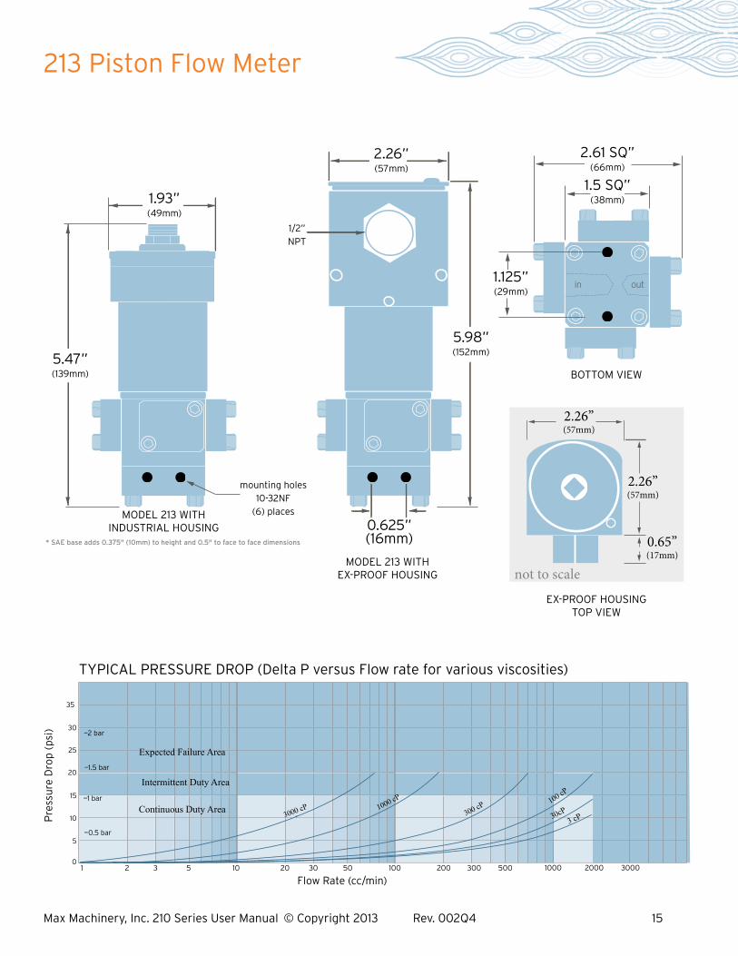
213 Piston Flow Meter
* SAE base adds 0.375" (10mm) to height and 0.5" to face to face dimensions
BOTTOM VIEW
in out
BOTTOM VIEW
MODEL 213 WITH EX-PROOF HOUSING
MODEL 213 WITH INDUSTRIAL HOUSING
EX-PROOF HOUSING TOP VIEW
not to scale
2.26” (57mm)
2.26” (57mm)
0.65” (17mm)
2.26” (57mm)
5.98” (152mm)
1.93” (49mm)
5.47” (139mm)
2.61 SQ” (66mm)
1.5 SQ” (38mm)
1/2” NPT
mounting holes 10-32NF
(6) places
0.625”(16mm)
1.125” (29mm)
300 cP
100 cP
3 cP
Flow Rate (cc/min)
Pre
ssu
re D
rop
(ps
i)
0
30
35
5
10
15
20
25
TYPICAL PRESSURE DROP (Delta P versus Flow rate for various viscosities)
1 2 3 5 10 20 30 50 100 200 300 500 1000 2000 3000
—2 bar
—1.5 bar
—1 bar
—0.5 bar
Intermittent Duty Area
Expected Failure Area
Continuous Duty Area
3000 cP
30cP
1000 cP
Max Machinery, Inc. 210 Series User Manual © Copyright 2013 Rev. 002Q4 16
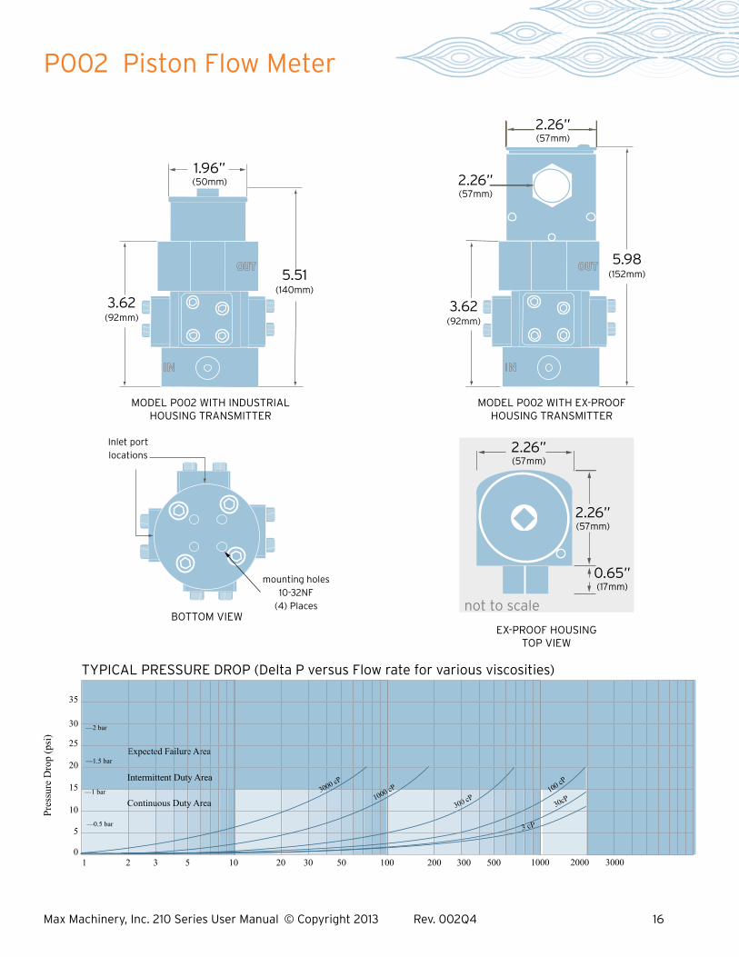
P002 Piston Flow Meter Pr
essu
re D
rop
(psi
)
TYPICAL PRESSURE DROP (Delta P versus Flow rate for various viscosities)
0
30
35
5
10
15
20
25
1 2 3 5 10 20 30 50 100 200 300 500 1000 2000 3000
—2 bar
—1.5 bar
—0.5 bar
Expected Failure Area
30cP
Intermittent Duty Area
Continuous Duty Area
3000 cP
1000 cP
300 cP
100 cP
3 cP
—1 bar
BOTTOM VIEW
MODEL P002 WITH INDUSTRIAL HOUSING TRANSMITTER
MODEL P002 WITH EX-PROOF HOUSING TRANSMITTER
EX-PROOF HOUSING TOP VIEW
not to scale
2.26” (57mm)
2.26” (57mm)
0.65” (17mm)
1.96” (50mm)
5.51 (140mm)
3.62 (92mm)
2.26” (57mm)
5.98 (152mm)
3.62 (92mm)
2.26” (57mm)
Inlet port locations
mounting holes 10-32NF
(4) Places

Max Machinery, Inc. 210 Series User Manual © Copyright 2013 Rev. 002Q4 17
214 Piston Flow Meter
3 cP
Expected Failure Area
Continuous Duty Area
Intermittent Duty Area
3
000 cP
1000 cP
30 cP
Flow Rate (cc/min)
Pres
sure
Dro
p (p
si)
0
30
35
5
10
15
20
25
TYPICAL PRESSURE DROP (Delta P versus Flow rate for various viscosities)
10 20 30 50 100 200 300 500 1000 2k 3k 5k 10k
—0.5 bar
—1 bar
—1.5 bar
—2 bar
100 cP
3
00 cP
4.875 SQ” (124mm)
BOTTOM VIEW
MODEL 214 WITH INDUSTRIAL HOUSING TRANSMITTER
MODEL 214 WITH EX-PROOF HOUSING TRANSMITTER
EX-PROOF HOUSING TOP VIEW
not to scale
2.26” (57mm)
2.26” (57mm)
0.65” (17mm)
1.93” (49mm)
6.3” (160mm)
2.57” (65mm)
2.26” (57mm)
6.61” (168mm)
2.57” (65mm)
in out 3.00 SQ” (76mm)
1/2” FNPT
mounting holes 1/4-20NC (6) places
1.125”(29mm)
2.125” (54mm)
Max Machinery, Inc. 210 Series User Manual © Copyright 2013 Rev. 002Q4 18
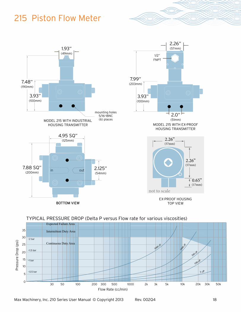
215 Piston Flow Meter
Flow Rate (cc/min)
Pre
ssu
re D
rop
(ps
i)
0
30
35
5
10
15
20
25
TYPICAL PRESSURE DROP (Delta P versus Flow rate for various viscosities)
30 50 100 200 300 500 1000 2k 3k 5k 10k 20k 30k 50k
—2 bar
—1.5 bar
—1 bar
—0.5 bar
Intermittent Duty Area
Expected Failure Area
Continuous Duty Area
300 cP
3000 cP
100
0 cP
100 cP
3 cP
MODEL 215 WITH INDUSTRIAL HOUSING TRANSMITTER MODEL 215 WITH EX-PROOF
HOUSING TRANSMITTER
EX-PROOF HOUSING TOP VIEW
not to scale
2.26” (57mm)
2.26” (57mm)
0.65” (17mm)
1.93” (49mm)
7.48” (190mm)
3.93” (100mm)
2.26” (57mm)
1/2” FNPT
7.99” (203mm)
3.93” (100mm)
mounting holes 5/16-18NC (6) places
2.0” (51mm)
BOTTOM VIEWBOTTOM VIEW
in out7.88 SQ”
(200mm) 2.125” (54mm)
4.95 SQ” (125mm)

Max Machinery, Inc. 210 Series User Manual © Copyright 2013 Rev. 002Q4 19
216 Piston Flow Meter
MODEL 216 WITH INDUSTRIAL HOUSING TRANSMITTER
EX-PROOF HOUSING TOP VIEW
not to scale
2.26” (57mm)
2.26” (57mm)
0.65” (17mm)
4.825” (123mm)
8.94” (227mm)
mounting holes 3/8”-16NC (6) places
in out
BOTTOM VIEW
9.5 SQ” (241mm)
3.00” (76mm)
1.93” (49mm)
MODEL 216 WITH EX-PROOF HOUSING TRANSMITTER
9.45” (240mm)
5.39” (137mm)
2.26” (57mm)
1/2” FNPT
3.0” (76mm)
7.0 SQ” (178mm)
^t
1000 cp
s
3 cps
10
0 cps
300 cps
Flow Rate (L/min)
0
30
35
5
10
15
20
25
TYPICAL PRESSURE DROP (Delta P versus Flow rate for various viscosities)
0.1 0.2 0.3 0.5 1 2 3 5 10 20 30 50 100
—2 bar
—1.5 bar
—0.5 bar
Intermittent Duty Area
Expected Failure Area
Continuous Duty Area
3000 cp
s
Pre
ssu
re D
rop
(ps
i)

Max Machinery, Inc. 210 Series User Manual © Copyright 2013 Rev. 002Q4 20
The Max 210 Meter Series is not designed for user repair and all such work should be done at the factory or under the direct supervision of the Max Technical Service Department. Unauthorized repair work may damage the meter and will void the product warranty. Please make note of model and serial numbers on the flow meter before calling the factory. A return goods authorization number will be issued if the flow meter has to be sent back for repair.
Max Machinery, Inc. Phone: 707-433-2662 33A Healdsburg Ave Fax: 707-433-1818 Healdsburg, CA 95448 www.maxmachinery.com
Contact for Repairs & Calibration Services