Embed Size (px)
Citation preview
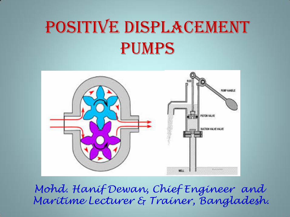
Positive Displacement
PumpS
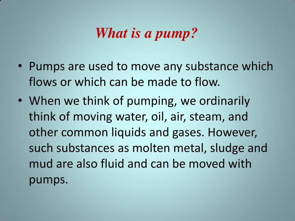
• Pumps are used to move any substance which
flows or which can be made to flow.
• When we think of pumping, we ordinarily
think of moving water, oil, air, steam, and
other common liquids and gases. However,
such substances as molten metal, sludge and
mud are also fluid and can be moved with
pumps.
What is a pump?
• Pumps are so widely used, for varied services.
As a general rule, all pumps are designed to
move fluid substances from one point to
another by pulling, pushing or throwing or by
some combination of these three methods.
• A pump is a device that adds energy to the
fluid to enable it to move from one point to
another.
• Onboard ship, pumps are used for a number of
essential services.
• Pumps feed water to the boiler, draw condensate from
the condensers, supply seawater to the fire main,
circulate cooling water for coolers and condensers,
empty the bilges, transfer fuel oil, discharge fuel oil to
the burners and engines, and, serve many other
purposes.
• The ope atio of the ship’s p opulsio pla t a d al ost all auxiliary machinery depends upon the proper
operation of pumps.
• Pump failure may cause failure of an entire plant.
• Pumps are vitally important to the functioning
of the ship. If they fail, the power plants they
serve fail. In an emergency, pump failures can
prove disastrous.
Principles of Pump Operation
• A pu p’s p i a y pu pose is to ove li uid f o one point and deliver it to another, by pulling,
pushing, throwing or a combination of these
methods. Every pump has a power end, whether it
be a steam turbine, a reciprocating steam engine, a
steam jet, or some kind of electric motor. Each
pump also has a liquid end, where the liquid enters
(suction) and leaves (discharges) the pump.
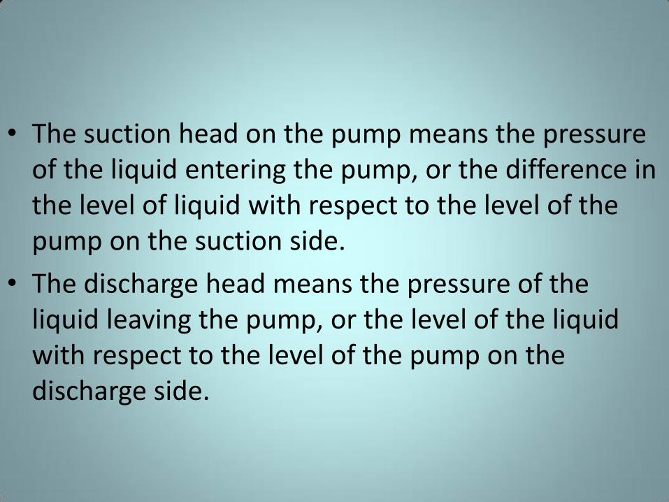
• The suction head on the pump means the pressure
of the liquid entering the pump, or the difference in
the level of liquid with respect to the level of the
pump on the suction side.
• The discharge head means the pressure of the
liquid leaving the pump, or the level of the liquid
with respect to the level of the pump on the
discharge side.
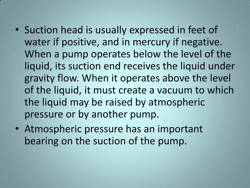
• Suction head is usually expressed in feet of water if positive, and in mercury if negative. When a pump operates below the level of the liquid, its suction end receives the liquid under gravity flow. When it operates above the level of the liquid, it must create a vacuum to which the liquid may be raised by atmospheric pressure or by another pump.
• Atmospheric pressure has an important bearing on the suction of the pump.
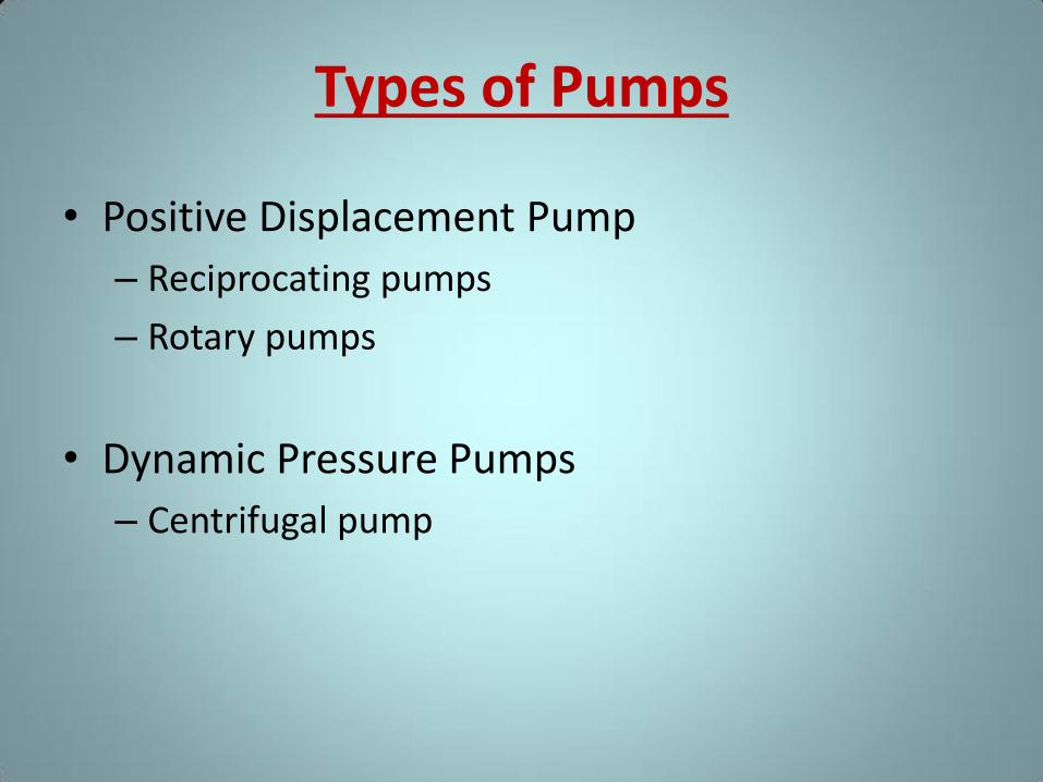
Types of Pumps
• Positive Displacement Pump
– Reciprocating pumps
– Rotary pumps
• Dynamic Pressure Pumps
– Centrifugal pump
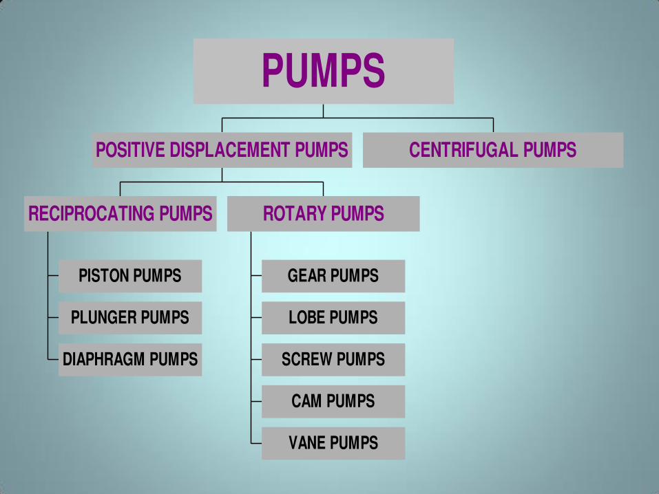
PISTON PUMPS
PLUNGER PUMPS
DIAPHRAGM PUMPS
RECIPROCATING PUMPS
GEAR PUMPS
LOBE PUMPS
SCREW PUMPS
CAM PUMPS
VANE PUMPS
ROTARY PUMPS
POSITIVE DISPLACEMENT PUMPS CENTRIFUGAL PUMPS
PUMPS
POSITIVE DISPLACEMENT
PUMP
• A positive displacement pump is one in which a definite constant volume of liquid is delivered for each cycle regardless of the resistance to flow offered by the system of pump operation.
• The positive displacement pump differs from centrifugal pumps, which deliver a continuous flow for any given pump speed and discharge resistance.
• Positive displacement pumps can be grouped into two basic categories based on their design and operation; – Reciprocating pumps,
– Rotary pumps,
RECIPROCATING PUMP/ PISTON PUMP
• Based on two stroke principles:
√ High pressure, high efficiency
√ Self-priming
X Small quantity, vibration, physical dimension, uneven flow
• Used mainly for handling slurries in plant processes and pipeline
applications
PISTON PUMPS
PLUNGER PUMPS
DIAPHRAGM PUMPS
RECIPROCATING PUMPS
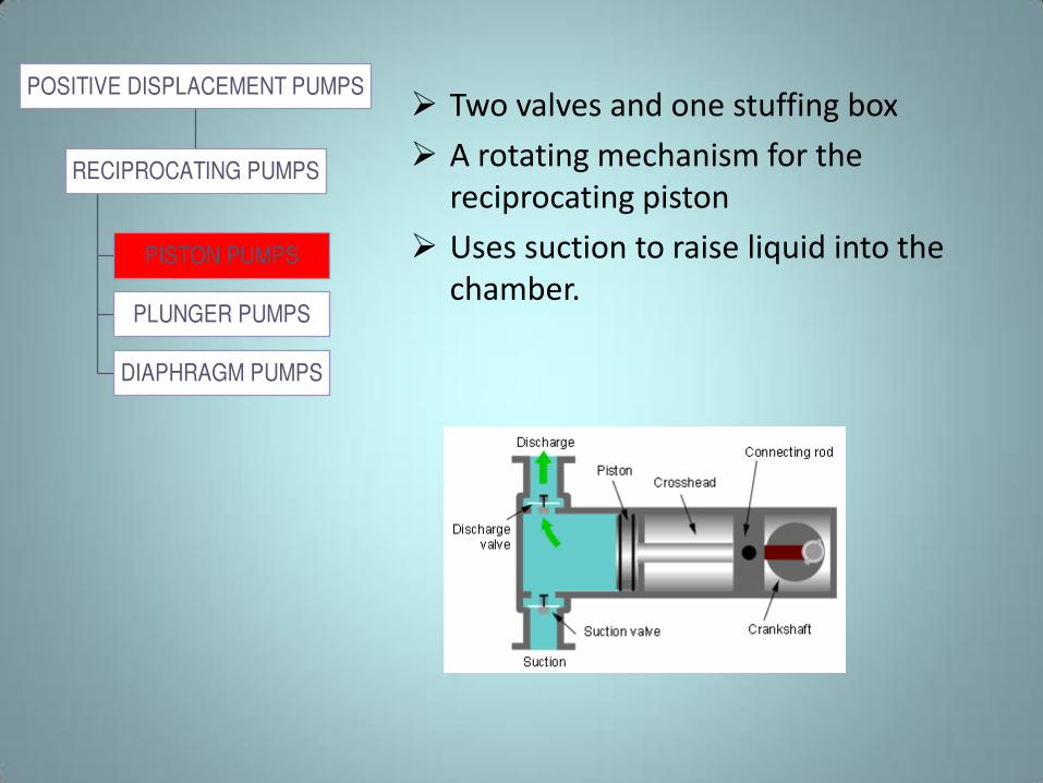
POSITIVE DISPLACEMENT PUMPS Two valves and one stuffing box
A rotating mechanism for the
reciprocating piston
Uses suction to raise liquid into the
chamber.
Reciprocating pump/Piston Pump
• This principle can be most easily
demonstrated by considering a reciprocating
positive displacement pump consisting of a
single reciprocating piston in a cylinder with a
single suction port and a single discharge
port.
• Check valves in the suction and discharge
ports allow flow in only one direction.
• During the suction stroke, the piston moves to the left, causing the check valve in the suction.
• During the discharge stroke, the piston moves to the right, seating the check valve in the suction line and opening the check valve in the discharge line.
• The volume of liquid moved by the pump in one cycle (one suction stroke and one discharge stroke) is equal to the change in the liquid volume of the cylinder as the piston moves from its farthest left position to its farthest right position.
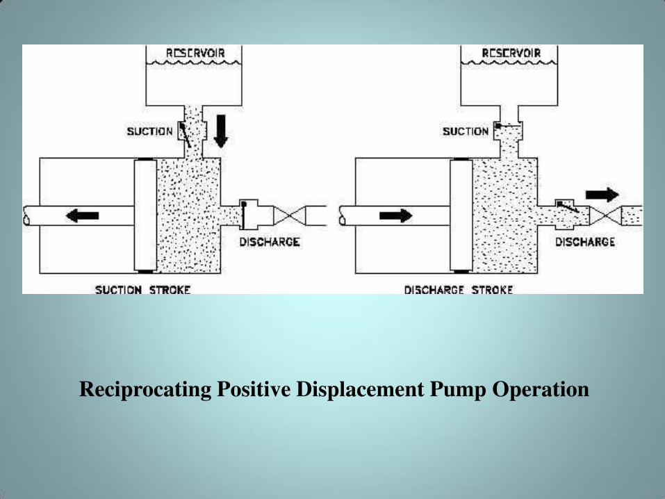
Reciprocating Positive Displacement Pump Operation
• Reciprocating positive displacement pumps
are generally categorized in four ways:
– Direct-acting or indirect-acting
– Simplex or duplex
– Single-acting or double-acting
– Power pumps.
Direct-Acting and Indirect-
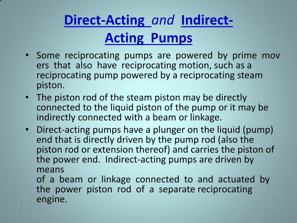
Acting Pumps • Some reciprocating pumps are powered by prime mov
ers that also have reciprocating motion, such as a reciprocating pump powered by a reciprocating steam piston.
• The piston rod of the steam piston may be directly connected to the liquid piston of the pump or it may be indirectly connected with a beam or linkage.
• Direct-acting pumps have a plunger on the liquid (pump) end that is directly driven by the pump rod (also the piston rod or extension thereof) and carries the piston of the power end. Indirect-acting pumps are driven by means of a beam or linkage connected to and actuated by the power piston rod of a separate reciprocating engine.
Simplex and Duplex Pumps
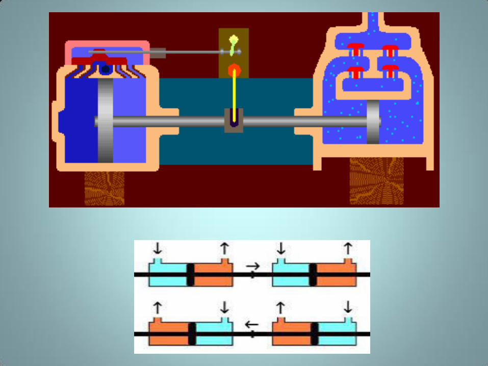
• A simplex pump, sometimes referred to as a single pump, is a pump having a single liquid (pump) cylinder. A duplex pump is the equivalent of two simplex pumps placed side by side on the same foundation.
• The driving of the pistons of a duplex pump is arranged in such a manner that when one piston is on its upstroke the other piston is on its downstroke, and vice versa. This arrangement doubles the capacity of the duplex pump compared to a simplex pump of comparable design.
Single-Acting and Double-
Acting Pumps
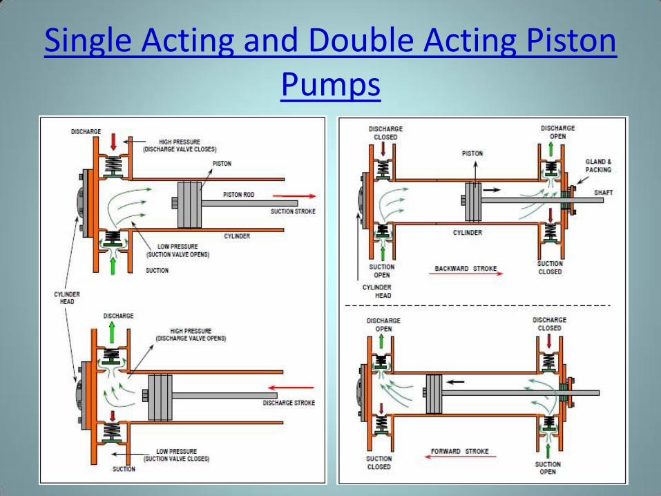
• A single-acting pump is one that takes a suction, filling the pump cylinder on the stroke in only one direction, called the suction stroke, and then forces the liquid out of the cylinder on the return stroke, called the discharge stroke.
• A double-acting pump is one that, as it fills one end of the liquid of the cylinder, is discharging liquid from the other end of the cylinder in the same stroke.
• On the return stroke, the end of the cylinder just emptied is filled, and the end just filled is emptied.
Single Acting and Double Acting Piston
Pumps
• The higher pressure units are normally single-acting plungers, and usually employ three (triplex) plungers. Three or more plungers substantially reduce flow pulsations relative to simplex and even duplex pumps.
• Power pumps typically have high efficiency and are capable of developing very high pressures.
• They can be driven by either electric motors or turbines. They are relatively expensive pumps and can rarely be justified on the basis of efficiency over centrifugal pumps.
Some Advantages of Piston Pumps
- Reciprocating pumps will deliver fluid at high pressure (High
Delivery Head).
- They are 'Self-priming' - No need to fill the cylinders before starting.
Some Disadvantages of Piston Pumps
- Reciprocating pumps give a pulsating flow.
- The suction stroke is difficult when pumping viscous liquids.
- The cost of producing piston pumps is high. This is due to the very
accurate sizes of the cylinders and pistons. Also, the gearing needed
to convert the rotation of the drive motor into a reciprocating action
involves extra equipment and cost.
- The close fitting moving parts cause maintenance problems,
especially when the pump is handling fluids containing suspended
solids, as the particles can get into the small clearances and cause
severe wear. The piston pump therefore, should not be used for
slurries.
- They give low volume rates of flow compared to other types of
pump.
CONVERTING ROTATION INTO RECIPROCATION
• The electric motor drives a fly-wheel or cam-shaft which is connected eccentrically to a connecting rod. The other end of the connecting rod is coupled to a 'Cross-head Gear' and 'Slide Assembly'. (This arrangement is the basis of the operation of the old Steam Engine drive cylinders and pistons).
• As the motor rotates the fly-wheel or cam, the eccentrically mounted connecting rod rotates with it. This causes the rod to move up and down and backwards and forwards. The up and down motion cannot be transmitted to the pump shaft - it would not work. We do however, need the back and forth movement.
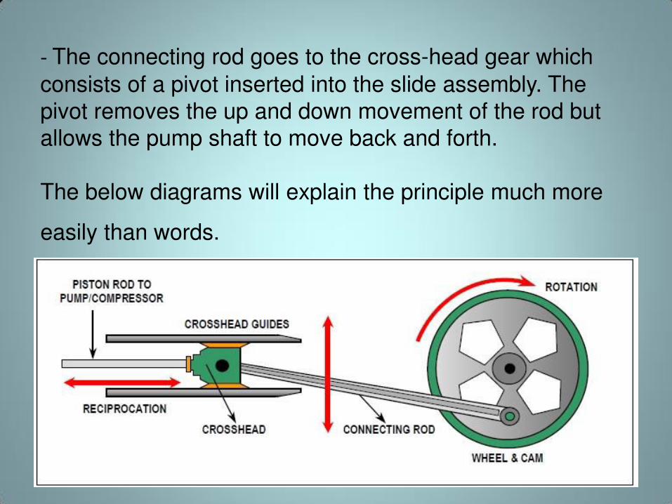
- The connecting rod goes to the cross-head gear which
consists of a pivot inserted into the slide assembly. The
pivot removes the up and down movement of the rod but
allows the pump shaft to move back and forth.
The below diagrams will explain the principle much more
easily than words.
PISTON PUMPS
PLUNGER PUMPS
DIAPHRAGM PUMPS
RECIPROCATING PUMPS
POSITIVE DISPLACEMENT PUMPS
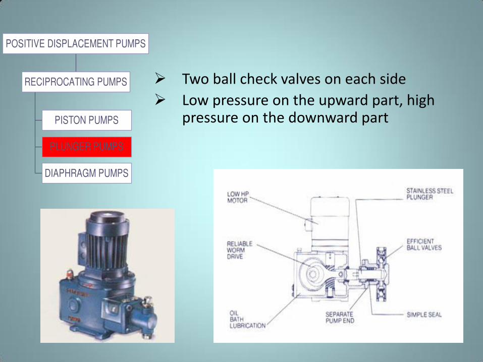
Two ball check valves on each side
Low pressure on the upward part, high pressure on the downward part
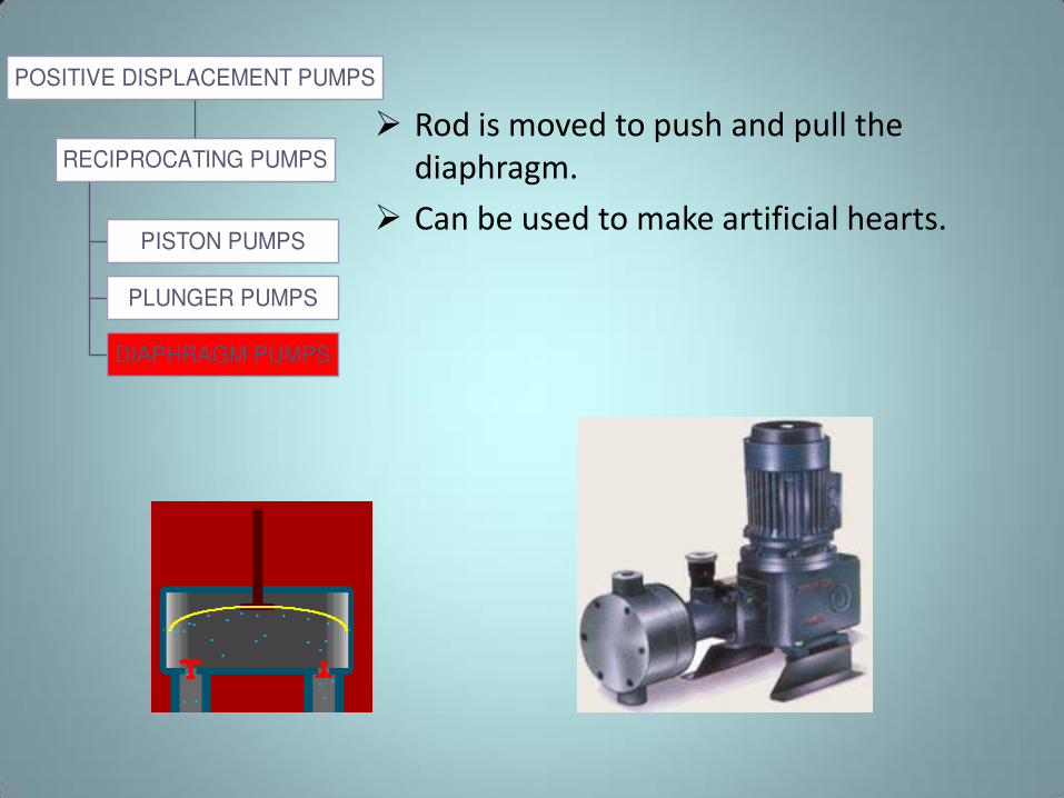
Rod is moved to push and pull the
diaphragm.
Can be used to make artificial hearts. PISTON PUMPS
PLUNGER PUMPS
DIAPHRAGM PUMPS
RECIPROCATING PUMPS
POSITIVE DISPLACEMENT PUMPS
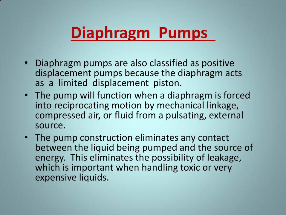
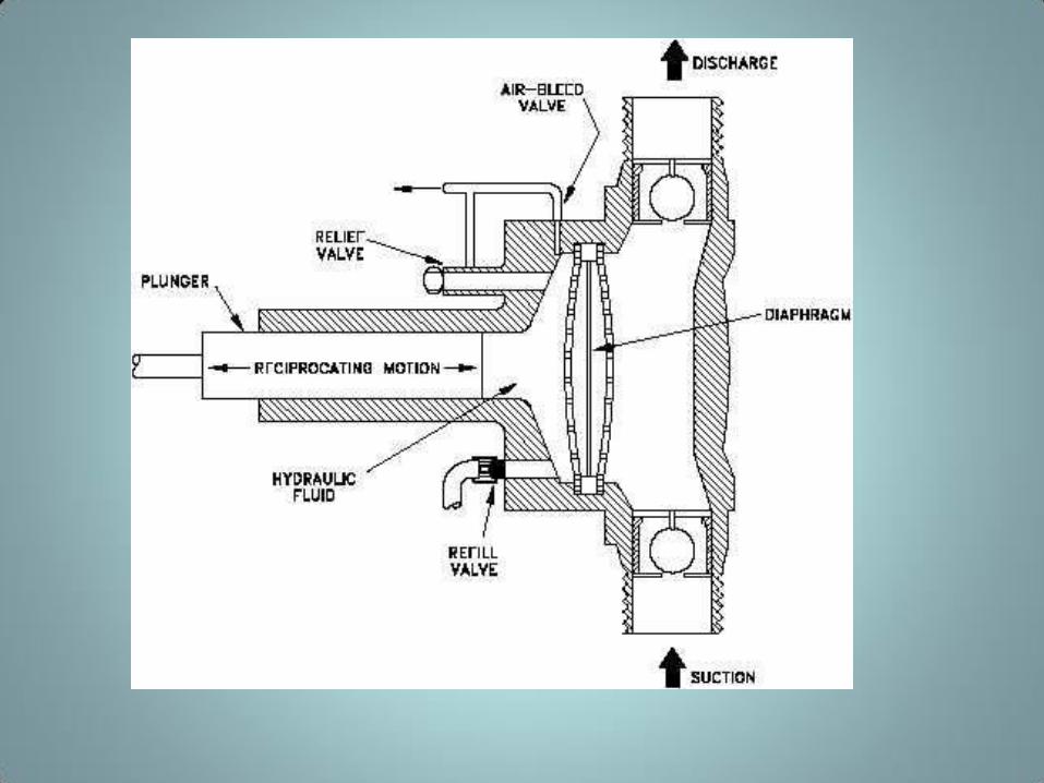
Diaphragm Pumps
• Diaphragm pumps are also classified as positive displacement pumps because the diaphragm acts as a limited displacement piston.
• The pump will function when a diaphragm is forced into reciprocating motion by mechanical linkage, compressed air, or fluid from a pulsating, external source.
• The pump construction eliminates any contact between the liquid being pumped and the source of energy. This eliminates the possibility of leakage, which is important when handling toxic or very expensive liquids.
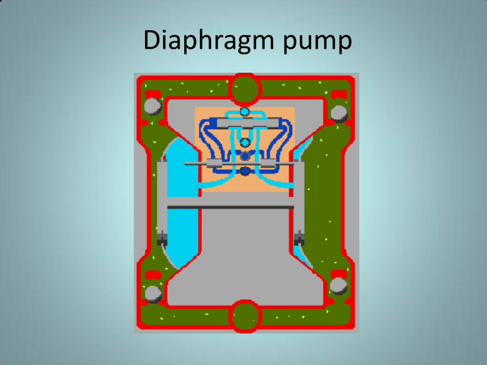
Diaphragm pump
• Disadvantages include limited head and
capacity range, and the necessity of check
valves in the suction and discharge nozzles.
Rotary pump
• Rotary pumps operate on the principle that a
rotating vane, screw, or gear traps the liquid in the
suction side of the pump casing and forces it to the
discharge side of the casing.
• These pumps are essentially self-priming due to their
capability of removing air from suction lines and
producing a high suction lift.
• In pumps designed for systems requiring high
suction lift and self- priming features, it is
essential that all clearances between rotating
parts, and between rotating and stationary
parts, be kept to a minimum in order to
reduce slippage.
• Slippage is leakage of fluid from the discharge
of the pump back to its suction.
• Due to the close clearances in rotary pumps, it is necessary to operate these pumps at relatively low speed in order to secure reliable operation and maintain pump capacity over an extended period of time.
• Otherwise, the erosive action due to the high velocities of the liquid passing through the narrow clearance spaces would soon cause excessive wear and increased clearances, resulting in slippage.
ROTARY PUMPS Positive displacement type
CHigh pressure, high efficiency
DLiquids must be free of solids
CHandle viscous fluids
• Used mainly in, oil burners, soaps and cosmetics, sugars,
syrup, and molasses, dyes, ink, bleaches, vegetable and
mineral oils
Types of Rotary Pumps
• There are many types of positive displacement rotary pumps, and they are normally grouped into 4 basic categories that include
– Gear pumps
– Lobe Pumps
– Screw pumps
– Cam Pumps
– vane pumps.
GEAR PUMPS
LOBE PUMPS
SCREW PUMPS
CAM PUMPS
VANE PUMPS
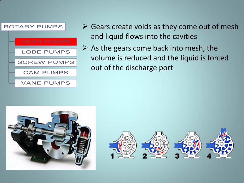
ROTARY PUMPS Gears create voids as they come out of mesh
and liquid flows into the cavities
As the gears come back into mesh, the
volume is reduced and the liquid is forced
out of the discharge port
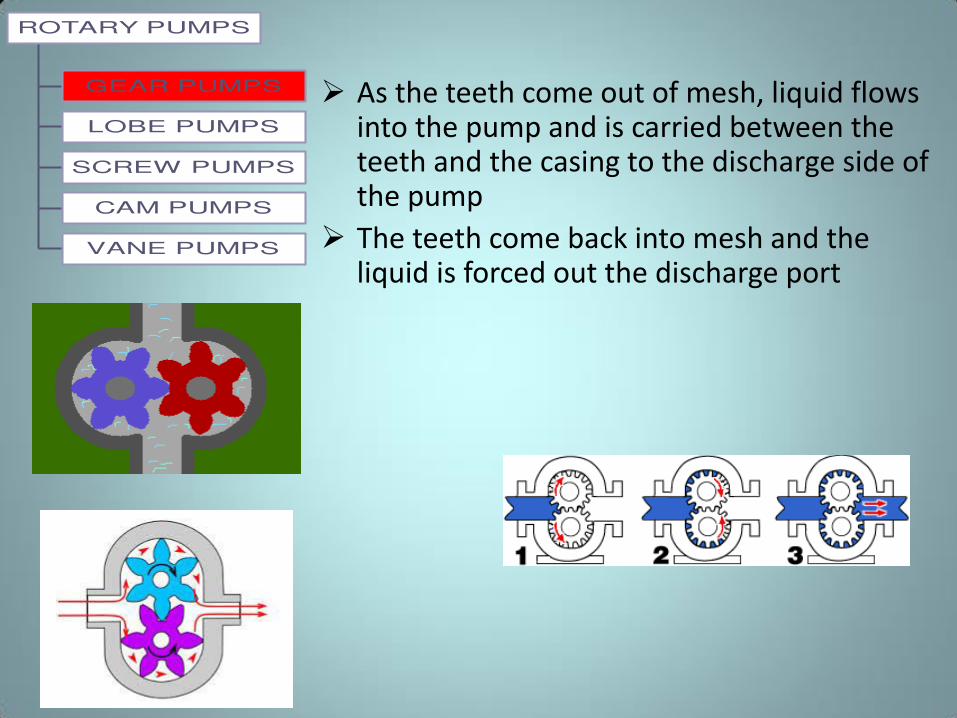
As the teeth come out of mesh, liquid flows into the pump and is carried between the teeth and the casing to the discharge side of the pump
The teeth come back into mesh and the liquid is forced out the discharge port
GEAR PUMPS
LOBE PUMPS
SCREW PUMPS
CAM PUMPS
VANE PUMPS
ROTARY PUMPS
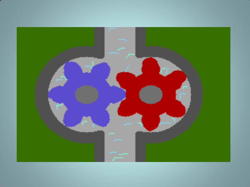
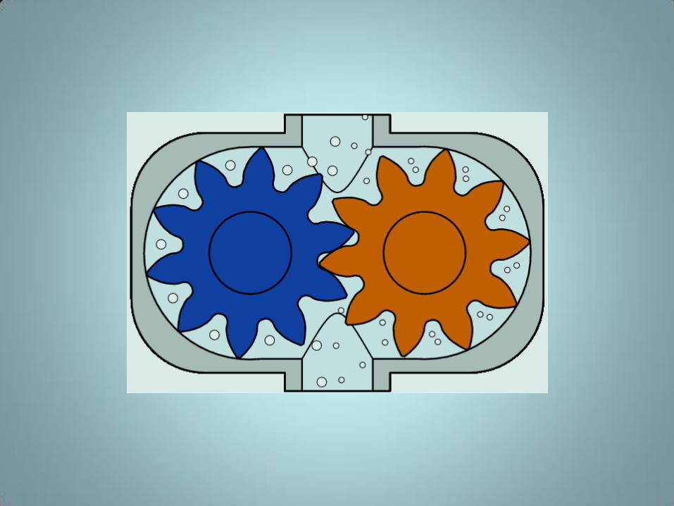
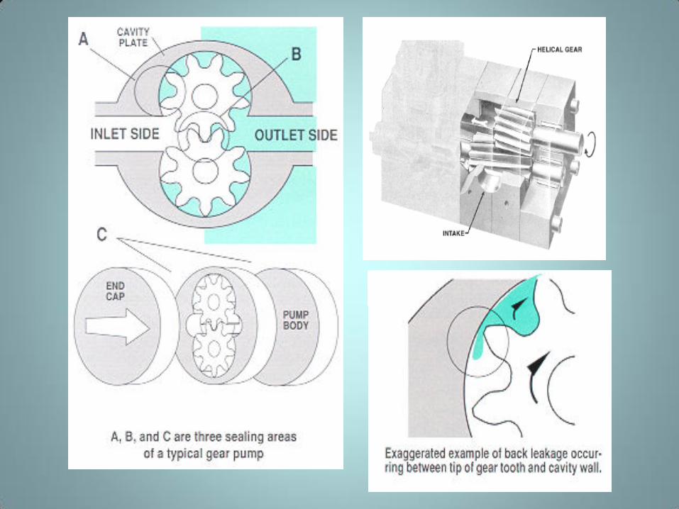
Simple gear pump
• There are several variations of a simple gear
pump consists of two spur gears meshing
together and revolving in opposite directions
within a casing. Only a few thousandths of an
inch clearance exists between the case and
the gear faces and teeth extremities
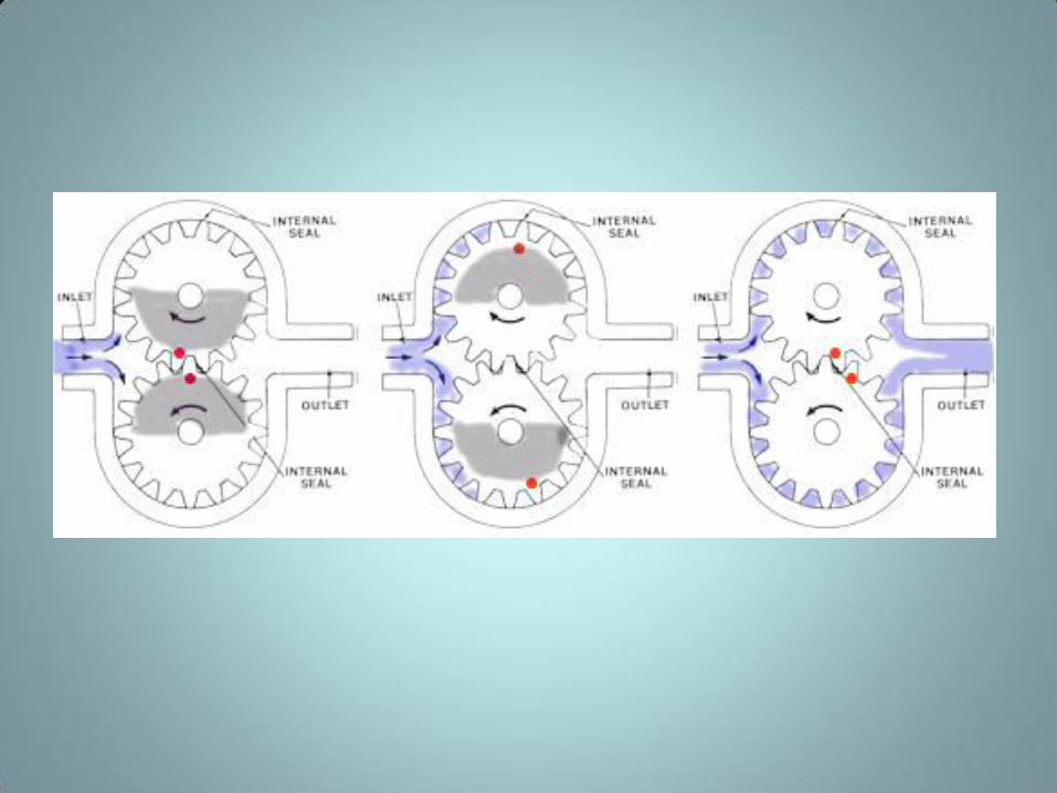
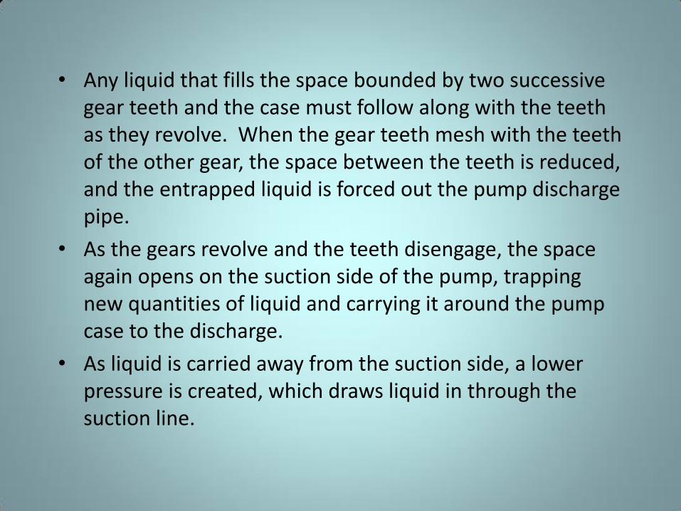
• Any liquid that fills the space bounded by two successive
gear teeth and the case must follow along with the teeth
as they revolve. When the gear teeth mesh with the teeth
of the other gear, the space between the teeth is reduced,
and the entrapped liquid is forced out the pump discharge
pipe.
• As the gears revolve and the teeth disengage, the space
again opens on the suction side of the pump, trapping
new quantities of liquid and carrying it around the pump
case to the discharge.
• As liquid is carried away from the suction side, a lower
pressure is created, which draws liquid in through the
suction line.
• With the large number of teeth usually employed on the gears, the discharge is relatively smooth and continuous, with small quantities of liquid being delivered to the discharge line in rapid succession.
• If designed with fewer teeth, the space between the teeth is greater and the capacity increases for a given speed; however, the tendency toward a pulsating discharge increases.
• There are no valves in the gear pump to cause friction losses as in the reciprocating pump. Therefore, the gear pump is well suited for handling viscous fluids such as fuel and lubricating oils.
Other Gear Pumps
• There are two types of gears used in gear pumps in addition to the simple spur gear.
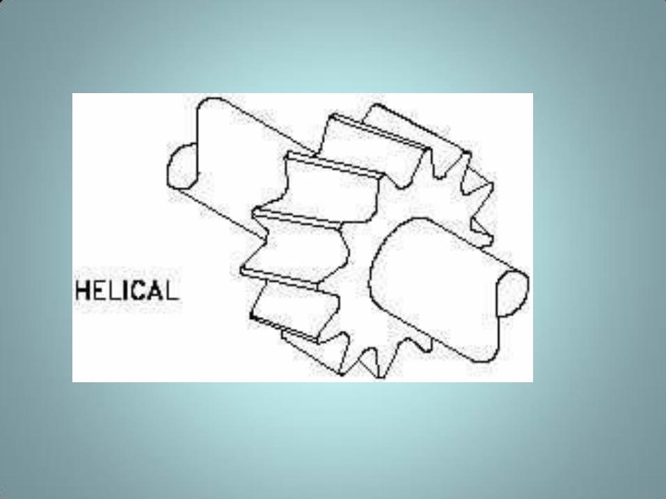
– Helical gear.
• A helix is the curve produced when a straight line moves up or down the surface of a cylinder.
– Herringbone gear.
• A herringbone gear is composed of two helixes spiraling in different directions from the center of the gear.
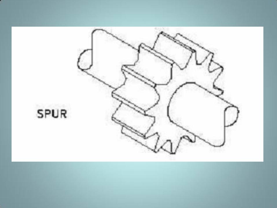
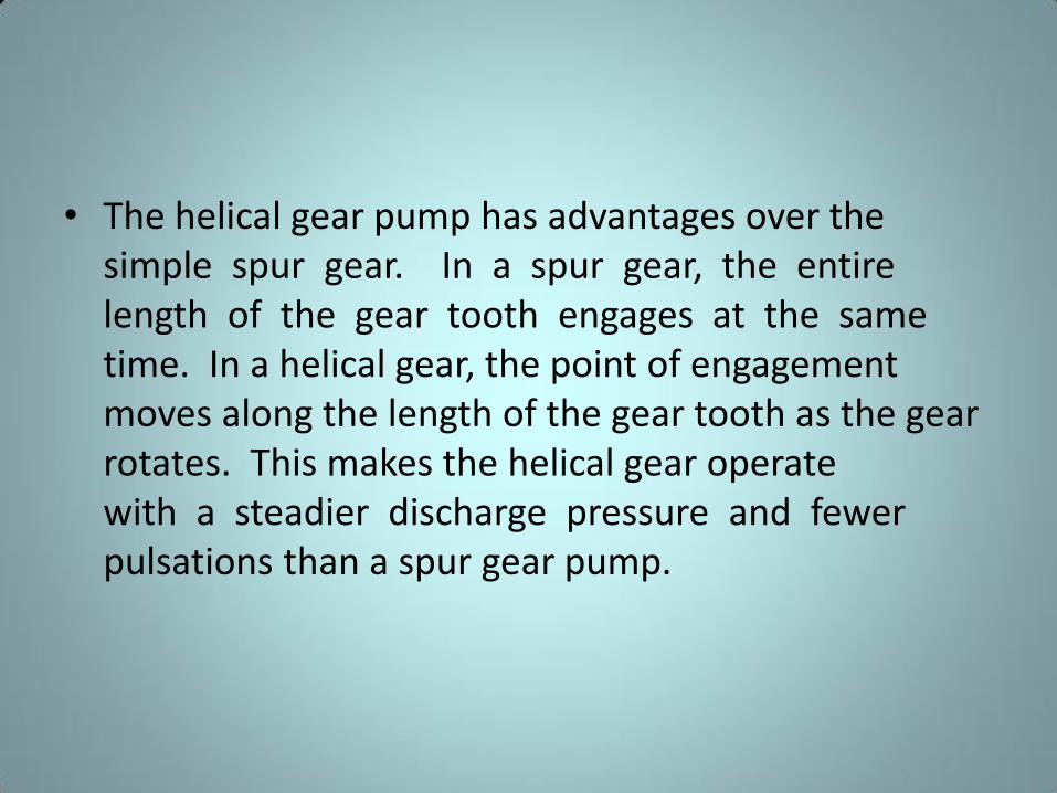
• The helical gear pump has advantages over the
simple spur gear. In a spur gear, the entire
length of the gear tooth engages at the same
time. In a helical gear, the point of engagement
moves along the length of the gear tooth as the gear
rotates. This makes the helical gear operate
with a steadier discharge pressure and fewer
pulsations than a spur gear pump.
• The herringbone gear pump is also a modification of the simple gear pump. Its principal difference in operation from the simple spur gear pump is that the pointed center section of the space between two teeth begins discharging before the divergent outer ends of the preceding space complete discharging.
• This overlapping tends to provide a steadier discharge pressure. The power transmission from the driving to the driven gear is also smoother and quieter.

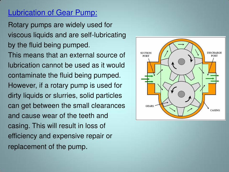
Lubrication of Gear Pump:
Rotary pumps are widely used for
viscous liquids and are self-lubricating
by the fluid being pumped.
This means that an external source of
lubrication cannot be used as it would
contaminate the fluid being pumped.
However, if a rotary pump is used for
dirty liquids or slurries, solid particles
can get between the small clearances
and cause wear of the teeth and
casing. This will result in loss of
efficiency and expensive repair or
replacement of the pump.
GEAR PUMPS
LOBE PUMPS
SCREW PUMPS
CAM PUMPS
VANE PUMPS
ROTARY PUMPS
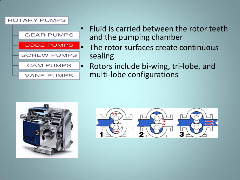
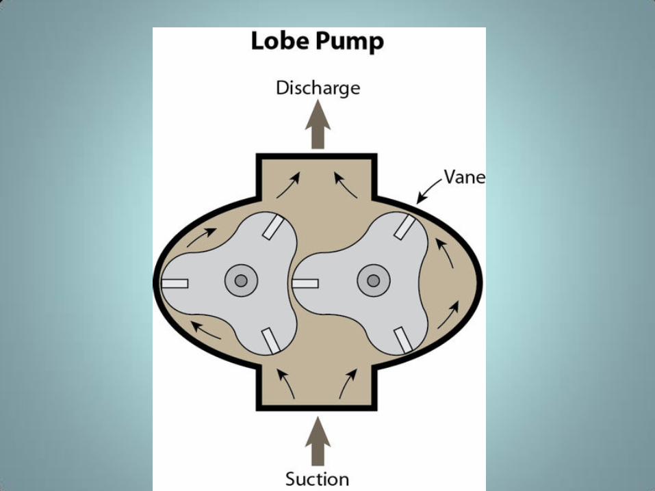
• Fluid is carried between the rotor teeth and the pumping chamber
• The rotor surfaces create continuous sealing
• Rotors include bi-wing, tri-lobe, and multi-lobe configurations
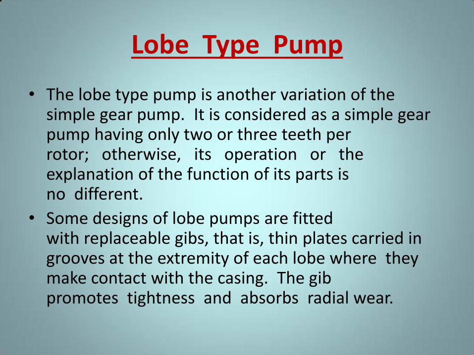
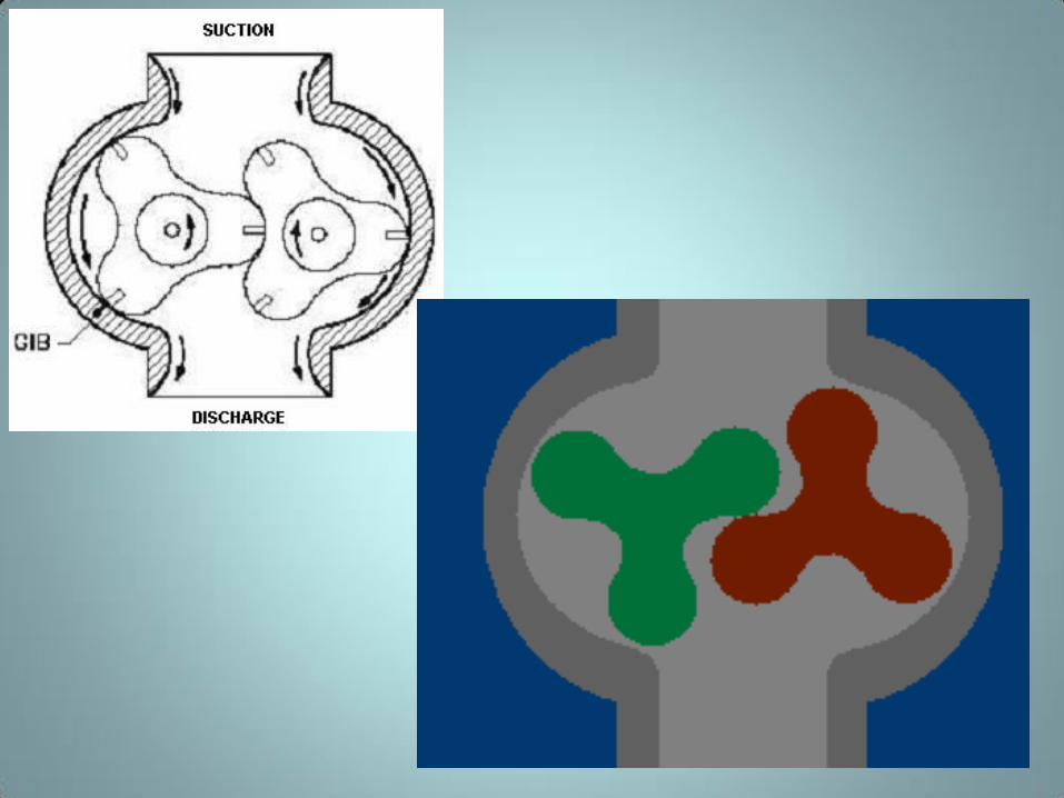
Lobe Type Pump
• The lobe type pump is another variation of the simple gear pump. It is considered as a simple gear pump having only two or three teeth per rotor; otherwise, its operation or the explanation of the function of its parts is no different.
• Some designs of lobe pumps are fitted with replaceable gibs, that is, thin plates carried in grooves at the extremity of each lobe where they make contact with the casing. The gib promotes tightness and absorbs radial wear.
GEAR PUMPS
LOBE PUMPS
SCREW PUMPS
CAM PUMPS
VANE PUMPS
ROTARY PUMPS
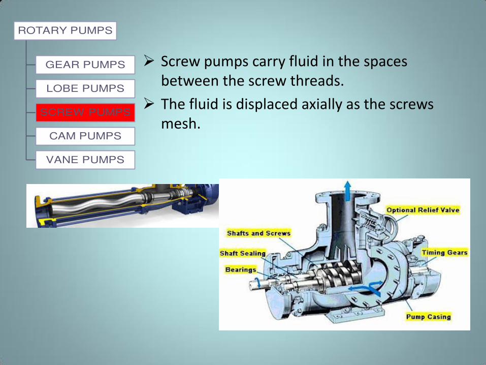
Screw pumps carry fluid in the spaces
between the screw threads.
The fluid is displaced axially as the screws
mesh.
Screw-Type Rotary Pump
• There are many variations in the design of the
screw type positive displacement, rotary pump.
The primary differences consist of the number of
intermeshing screws involved, the pitch of the
screws, and the general direction of fluid flow.
• Two common designs are
– Single screw
– Two-screw, low-pitch, double-flow pump
– Three-screw, high-pitch, double-flow pump.
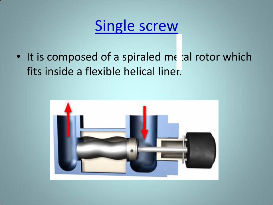
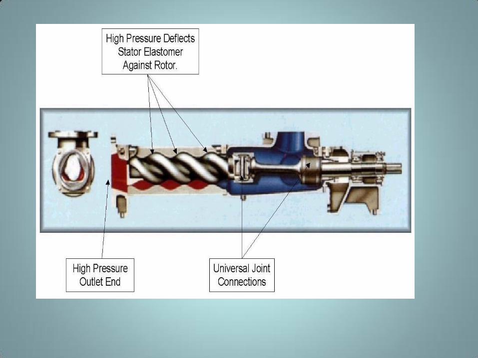
Single screw
• It is composed of a spiraled metal rotor which
fits inside a flexible helical liner.
Working Principle of Screw Pump:
• Screw pumps carry fluid in the spaces between the
screw threads. The fluid is displaced axially from the
suction port to the discharge port as the screws
mesh by the rotation of screws.
• Single screw pumps are commonly called progressive
cavity pumps. They have a rotor with external
threads and a stator with internal threads. The rotor
threads are eccentric to the axis of rotation.
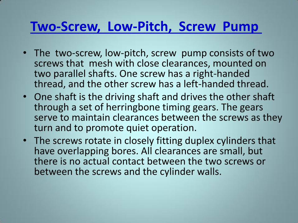
Two-Screw, Low-Pitch, Screw Pump
• The two-screw, low-pitch, screw pump consists of two screws that mesh with close clearances, mounted on two parallel shafts. One screw has a right-handed thread, and the other screw has a left-handed thread.
• One shaft is the driving shaft and drives the other shaft through a set of herringbone timing gears. The gears serve to maintain clearances between the screws as they turn and to promote quiet operation.
• The screws rotate in closely fitting duplex cylinders that have overlapping bores. All clearances are small, but there is no actual contact between the two screws or between the screws and the cylinder walls.
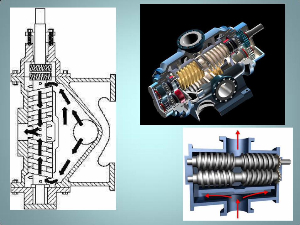
Working principle of Multi Screw
Pump:
• Liquid is trapped at the outer end of each pair of screws.
• As the first space between the screw threads rotates away from the opposite screw, a one-turn, spiral-shaped quantity of liquid is enclosed when the end of the screw again meshes with the opposite screw.
• As the screw continues to rotate, the entrapped spiral turns of liquid slide along the cylinder toward the center discharge space while the next liquid is being entrapped.
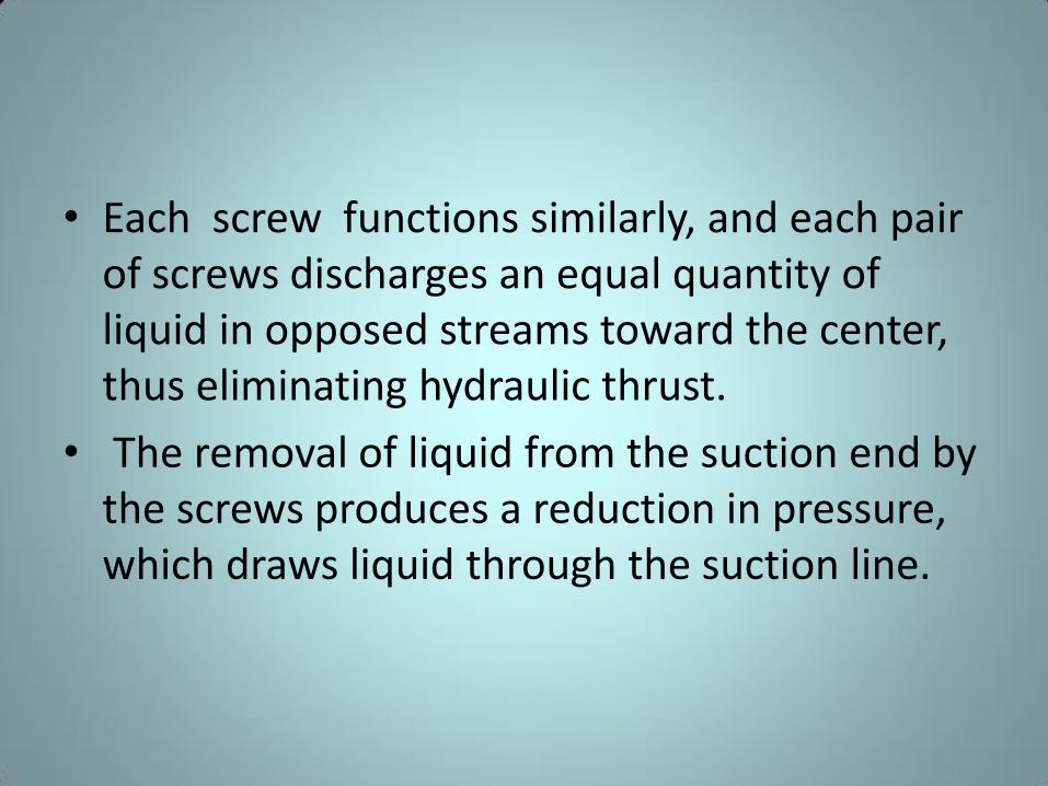
• Each screw functions similarly, and each pair
of screws discharges an equal quantity of
liquid in opposed streams toward the center,
thus eliminating hydraulic thrust.
• The removal of liquid from the suction end by
the screws produces a reduction in pressure,
which draws liquid through the suction line.
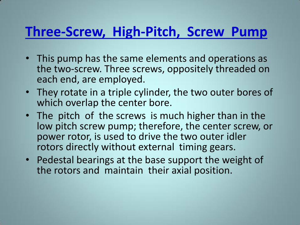
Three-Screw, High-Pitch, Screw Pump
• This pump has the same elements and operations as the two-screw. Three screws, oppositely threaded on each end, are employed.
• They rotate in a triple cylinder, the two outer bores of which overlap the center bore.
• The pitch of the screws is much higher than in the low pitch screw pump; therefore, the center screw, or power rotor, is used to drive the two outer idler rotors directly without external timing gears.
• Pedestal bearings at the base support the weight of the rotors and maintain their axial position.
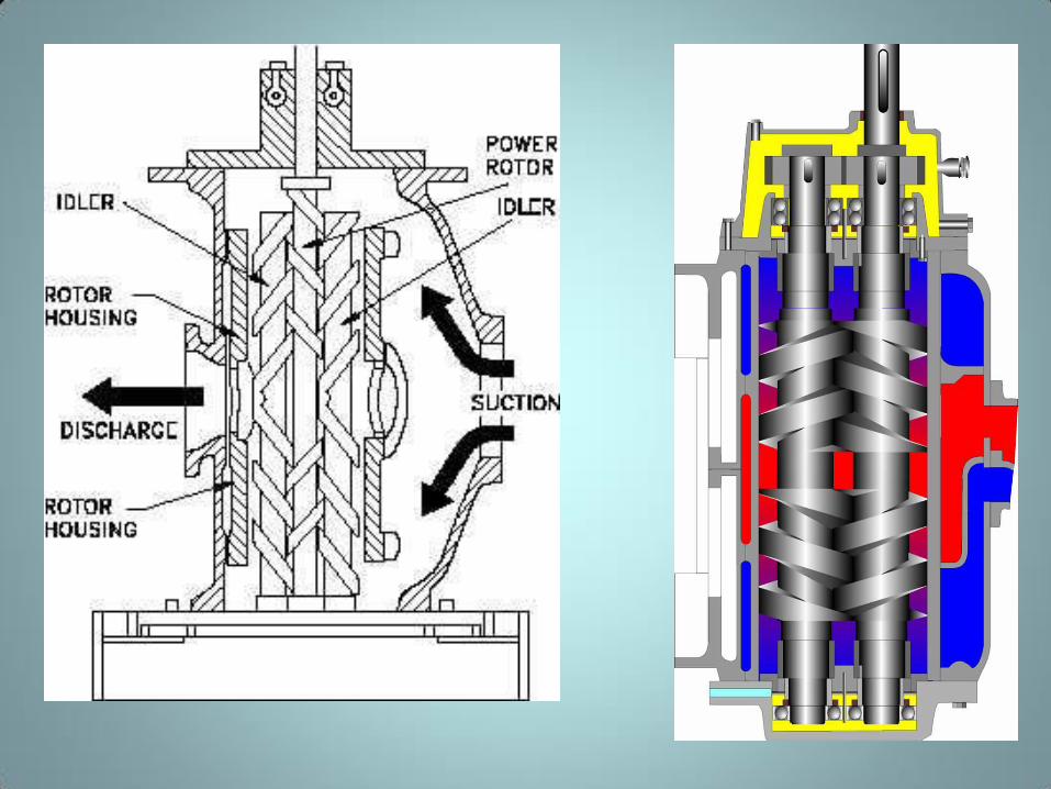
• The liquid being pumped enters the suction
opening, flows through passages around the rotor
housing, and through the screws from each end, in
opposed streams, toward the center discharge.
• This eliminates unbalanced hydraulic thrust. The
screw pump is used for pumping viscous
fluids, usually lubricating, hydraulic, or fuel oil.
GEAR PUMPS
LOBE PUMPS
SCREW PUMPS
CAM PUMPS
VANE PUMPS
ROTARY PUMPS
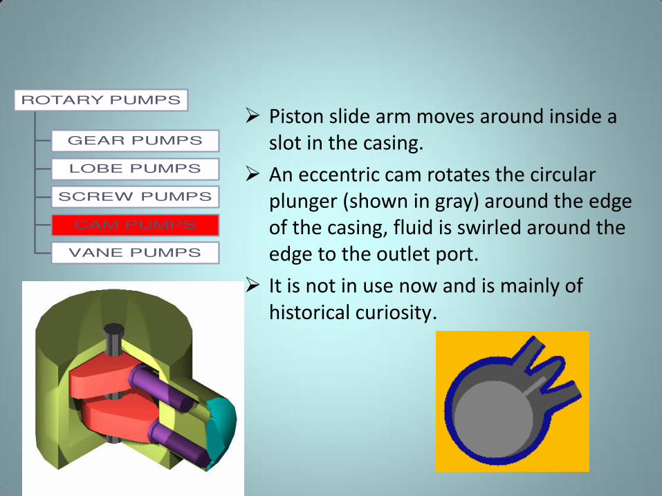
Piston slide arm moves around inside a
slot in the casing.
An eccentric cam rotates the circular
plunger (shown in gray) around the edge
of the casing, fluid is swirled around the
edge to the outlet port.
It is not in use now and is mainly of
historical curiosity.
GEAR PUMPS
LOBE PUMPS
SCREW PUMPS
CAM PUMPS
VANE PUMPS
ROTARY PUMPS
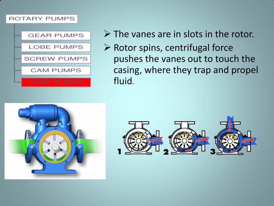
The vanes are in slots in the rotor.
Rotor spins, centrifugal force pushes the vanes out to touch the casing, where they trap and propel fluid.
Rotary Vane Pump
• The rotary moving vane pump is another type of positive displacement pump consists of a cylindrically bored housing with a suction inlet on one side and a discharge outlet on the other.
• A cylindrically shaped rotor with a diameter smaller than the cylinder is driven about an axis placed above the centerline of the cylinder.
• The clearance between rotor and cylinder is small at the top but increases at the bottom. The rotor carries pivoted vanes that move in and out as it rotates to maintain sealed spaces between the rotor and the cylinder wall.
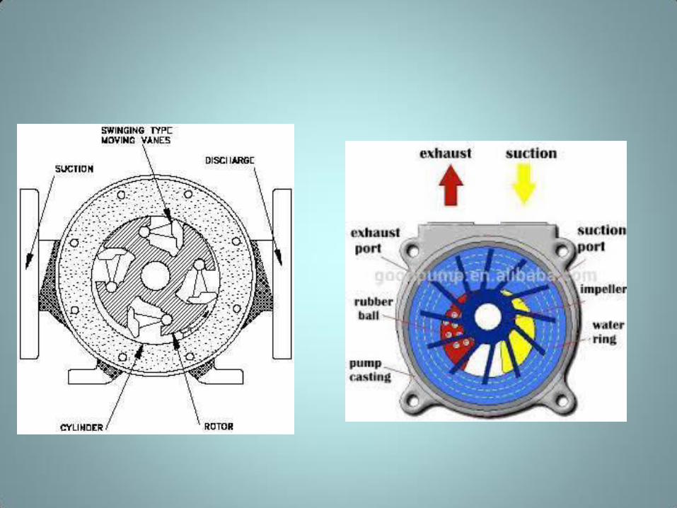
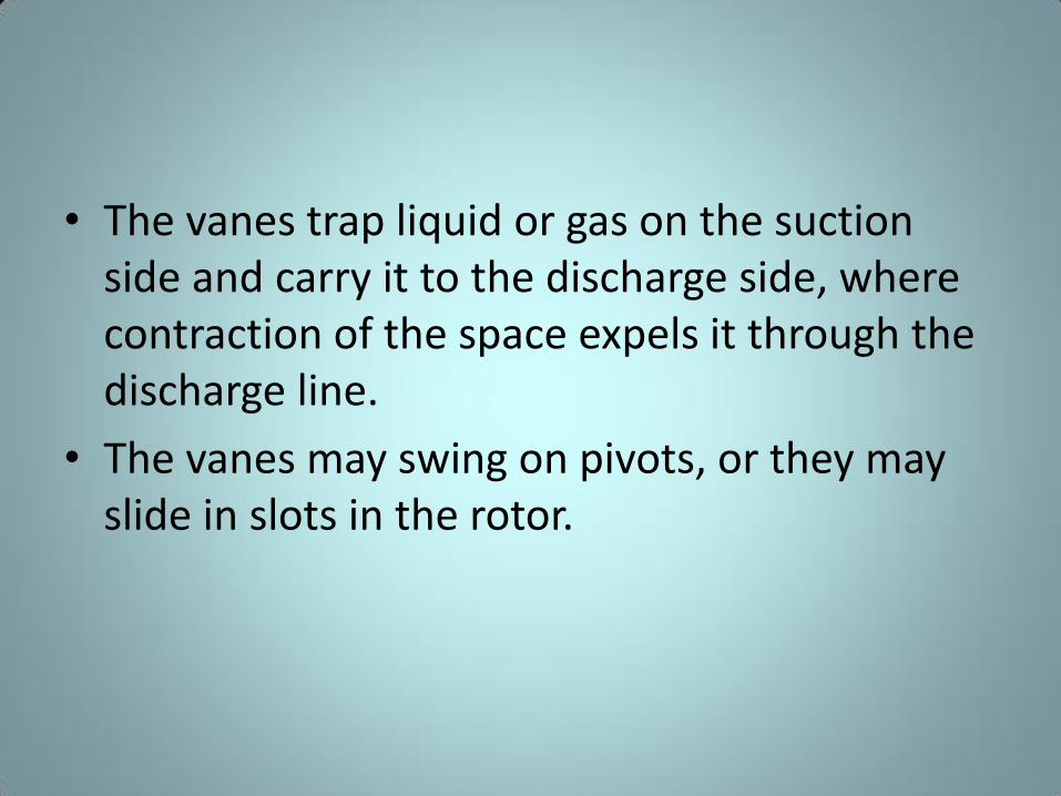
• The vanes trap liquid or gas on the suction
side and carry it to the discharge side, where
contraction of the space expels it through the
discharge line.
• The vanes may swing on pivots, or they may
slide in slots in the rotor.
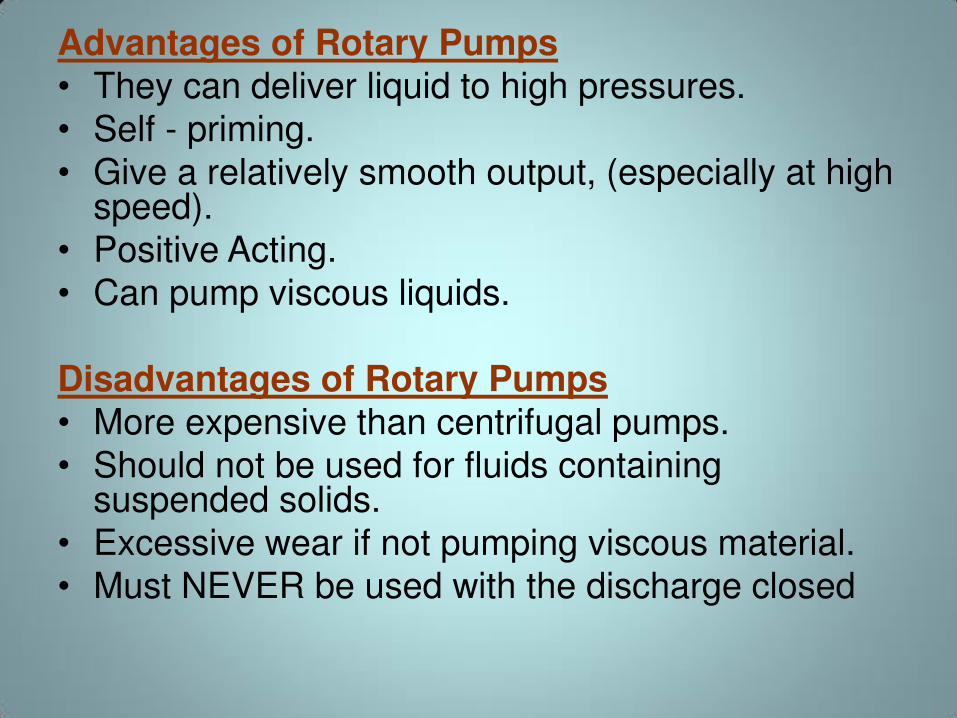
Advantages of Rotary Pumps
• They can deliver liquid to high pressures.
• Self - priming.
• Give a relatively smooth output, (especially at high speed).
• Positive Acting.
• Can pump viscous liquids.
Disadvantages of Rotary Pumps • More expensive than centrifugal pumps.
• Should not be used for fluids containing suspended solids.
• Excessive wear if not pumping viscous material.
• Must NEVER be used with the discharge closed
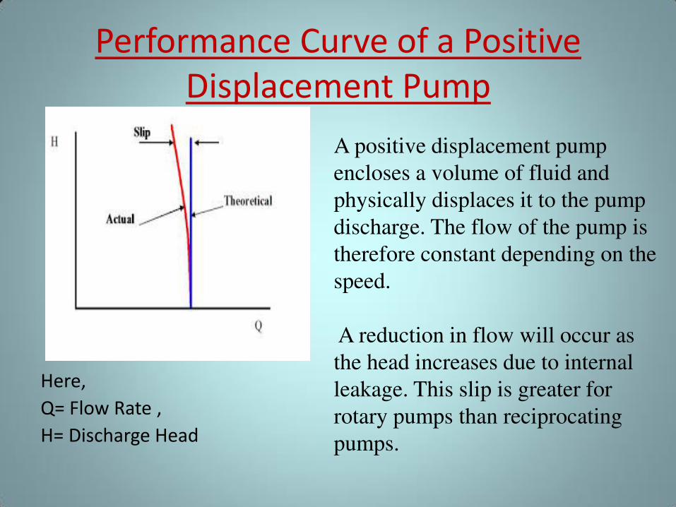
Performance Curve of a Positive
Displacement Pump
Here,
Q= Flow Rate ,
H= Discharge Head
A positive displacement pump
encloses a volume of fluid and
physically displaces it to the pump
discharge. The flow of the pump is
therefore constant depending on the
speed.
A reduction in flow will occur as
the head increases due to internal
leakage. This slip is greater for
rotary pumps than reciprocating
pumps.
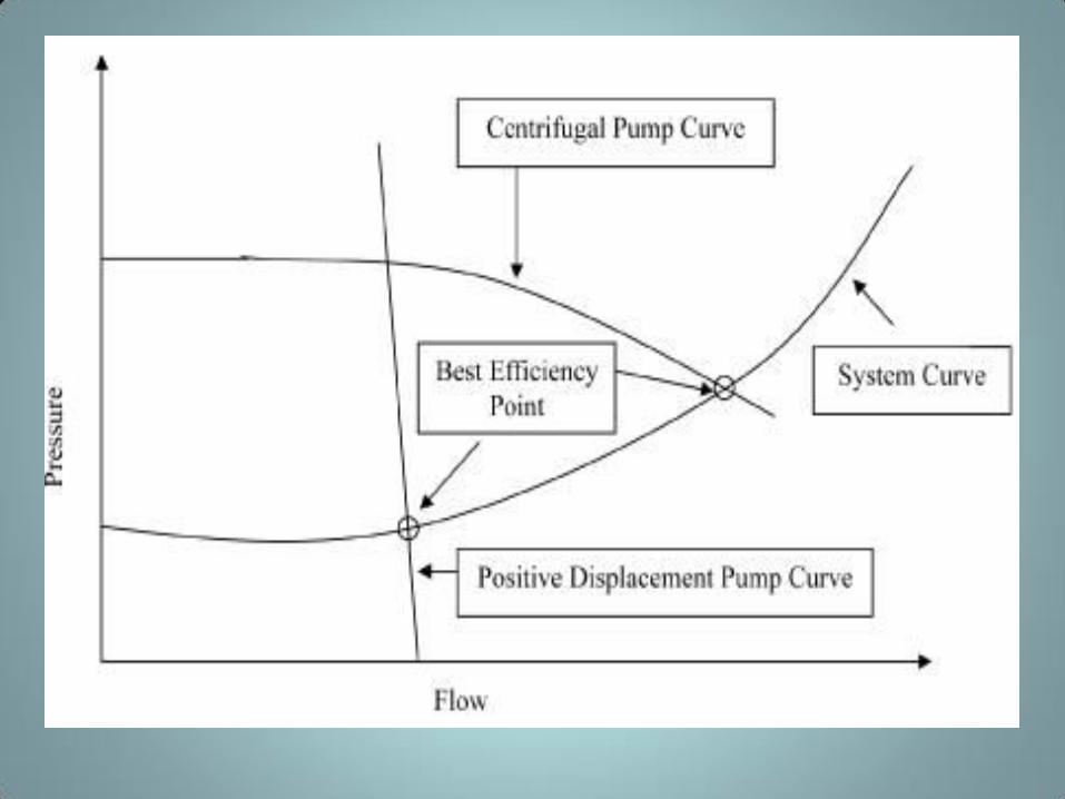
Performance: Centrifugal Pump Vs Positive
Displacement Pump • In a centrifugal pump, an impeller rotates to move liquid
through the process. The impeller's velocity imparts energy on the fluid. The resulting rise in pressure, or head, is proportional to the velocity of the liquid.
• In contrast, a positive displacement pump moves a set volume of liquid. Pressure is created as the liquid is forced through the pump discharge into the system. The pump converts energy into pressure. This is achieved as an increasing volume within the pumping chamber is opened to suction and then is filled, closed, moved to discharge and displaced. The delivered capacity is nearly constant throughout the discharge pressure range. This constant capacity or flow will intersect a system curve at a defined point, allowing a high degree of control.

ANY QUESTION?
THANK YOU! 4/1/2015
Mohd. Hanif Dewan, Chief Engineer and
Maritime Lecturer & Trainer, Bangladesh. 81