Embed Size (px)
Citation preview
8/2/2019 Positive Disp Pump
http://slidepdf.com/reader/full/positive-disp-pump 1/11
POSITIVE DISPLACEMENT PUMPS DOE-HDBK-1018/1-93 Pumps
POSITIVE DISPLACEMENT PUMPS
Positive displacement pumps operate on a different principle than centrifugal
pumps. Positive displacement pumps physically entrap a quantity of liquid at thesuction of the pump and push that quantity out the discharge of the pump.
EO 2.1 STATE the d if ference between the flow characteris tics of
centrifugal and positive displacement pumps.
EO 2.2 Given a simplified drawing of a positive d isplacement pump,
CLASSIFY the pump as one of the following:
a . Reciprocating pis ton pump
b. Gear-type rotary pump
c. Screw-type rotary pumpd. Lobe-type rotary pump
e. Moving vane pump
f. Diaphragm pump
EO 2.3 EXPLAIN the importance of viscosity as it relates to the
operation of a reciprocating positive displacement pump.
EO 2.4 D ES CR IBE the ch aracteristic cu rv e for a positiv e
displacement pump.
EO 2.5 DEFINE the term slippage.
EO 2 .6 STATE how positive d isplacement pumps are protected
against overpressurization.
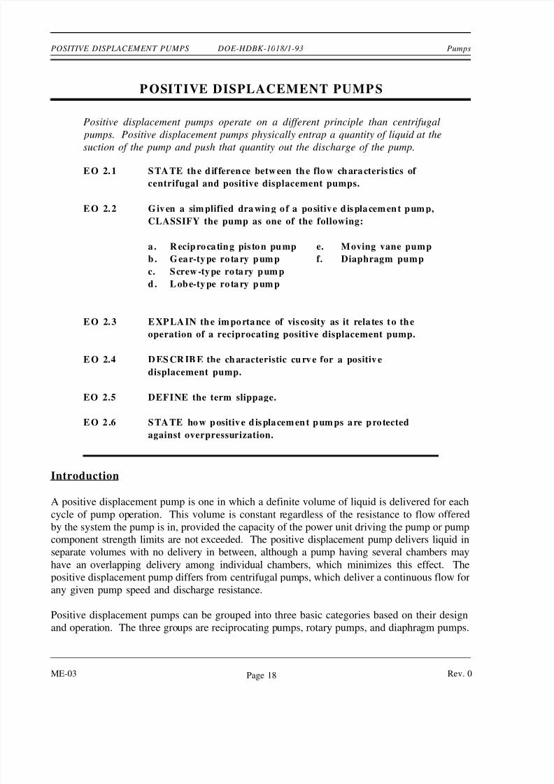
Introduction
A positive displacement pump is one in which a definite volume of liquid is delivered for each
cycle of pump operation. This volume is constant regardless of the resistance to flow offered
by the system the pump is in, provided the capacity of the power unit driving the pump or pump
component strength limits are not exceeded. The positive displacement pump delivers liquid in
separate volumes with no delivery in between, although a pump having several chambers mayhave an overlapping delivery among individual chambers, which minimizes this effect. The
positive displacement pump differs from centrifugal pumps, which deliver a continuous flow for
any given pump speed and discharge resistance.
Positive displacement pumps can be grouped into three basic categories based on their design
and operation. The three groups are reciprocating pumps, rotary pumps, and diaphragm pumps.
ME-03 Rev. 0Page 18
8/2/2019 Positive Disp Pump
http://slidepdf.com/reader/full/positive-disp-pump 2/11
Pumps DOE-HDBK-1018/1-93 POSITIVE DISPLACEMENT PUMPS
Principle of Operation
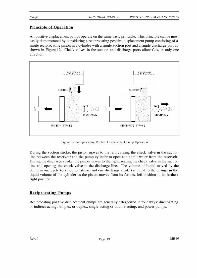
All positive displacement pumps operate on the same basic principle. This principle can be most
easily demonstrated by considering a reciprocating positive displacement pump consisting of a
single reciprocating piston in a cylinder with a single suction port and a single discharge port as
shown in Figure 12. Check valves in the suction and discharge ports allow flow in only onedirection.
During the suction stroke, the piston moves to the left, causing the check valve in the suction
Figure 12 Reciprocating Positive Displacement Pump Operation
line between the reservoir and the pump cylinder to open and admit water from the reservoir.
During the discharge stroke, the piston moves to the right, seating the check valve in the suction
line and opening the check valve in the discharge line. The volume of liquid moved by the
pump in one cycle (one suction stroke and one discharge stroke) is equal to the change in the
liquid volume of the cylinder as the piston moves from its farthest left position to its farthest
right position.
Reciprocating Pumps
Reciprocating positive displacement pumps are generally categorized in four ways: direct-acting
or indirect-acting; simplex or duplex; single-acting or double-acting; and power pumps.
Rev. 0 ME-03Page 19
8/2/2019 Positive Disp Pump
http://slidepdf.com/reader/full/positive-disp-pump 3/11
POSITIVE DISPLACEMENT PUMPS DOE-HDBK-1018/1-93 Pumps
Direct-Acting and Indirect-Acting Pumps
Some reciprocating pumps are powered by prime movers that also have reciprocating
motion, such as a reciprocating pump powered by a reciprocating steam piston. The piston
rod of the steam piston may be directly connected to the liquid piston of the pump or it may
be indirectly connected with a beam or linkage. Direct-acting pumps have a plunger on theliquid (pump) end that is directly driven by the pump rod (also the piston rod or extension
thereof) and carries the piston of the power end. Indirect-acting pumps are driven by means
of a beam or linkage connected to and actuated by the power piston rod of a separate
reciprocating engine.
Simplex and Duplex Pumps
A simplex pump, sometimes referred to as a single pump, is a pump having a single liquid
(pump) cylinder. A duplex pump is the equivalent of two simplex pumps placed side by
side on the same foundation.
The driving of the pistons of a duplex pump is arranged in such a manner that when one
piston is on its upstroke the other piston is on its downstroke, and vice versa. This
arrangement doubles the capacity of the duplex pump compared to a simplex pump of
comparable design.
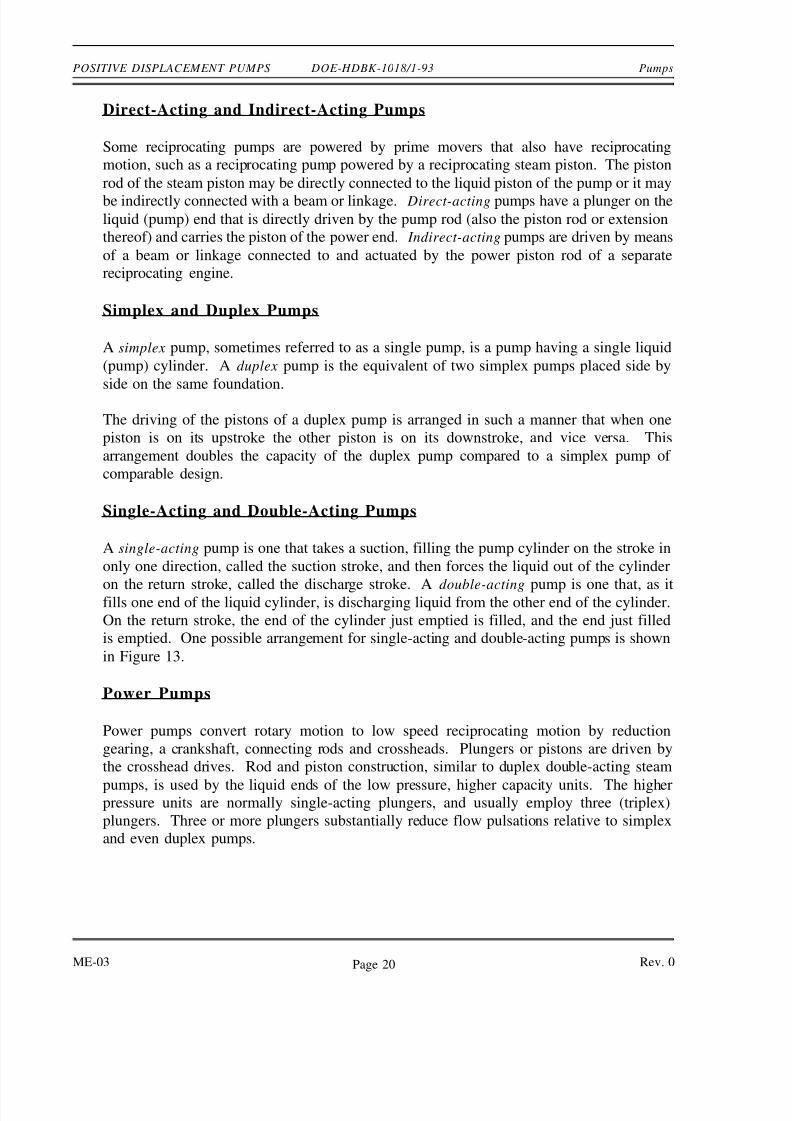
Single-Acting and Double-Acting Pumps
A single-acting pump is one that takes a suction, filling the pump cylinder on the stroke in
only one direction, called the suction stroke, and then forces the liquid out of the cylinder
on the return stroke, called the discharge stroke. A double-acting pump is one that, as itfills one end of the liquid cylinder, is discharging liquid from the other end of the cylinder.
On the return stroke, the end of the cylinder just emptied is filled, and the end just filled
is emptied. One possible arrangement for single-acting and double-acting pumps is shown
in Figure 13.
Power Pumps
Power pumps convert rotary motion to low speed reciprocating motion by reduction
gearing, a crankshaft, connecting rods and crossheads. Plungers or pistons are driven by
the crosshead drives. Rod and piston construction, similar to duplex double-acting steam
pumps, is used by the liquid ends of the low pressure, higher capacity units. The higherpressure units are normally single-acting plungers, and usually employ three (triplex)
plungers. Three or more plungers substantially reduce flow pulsations relative to simplex
and even duplex pumps.
ME-03 Rev. 0Page 20
8/2/2019 Positive Disp Pump
http://slidepdf.com/reader/full/positive-disp-pump 4/11
Pumps DOE-HDBK-1018/1-93 POSITIVE DISPLACEMENT PUMPS
Power pumps typically have high efficiency and are capable of developing very high pressures.
Figure 13 Single-Acting and Double-Acting Pumps
They can be driven by either electric motors or turbines. They are relatively expensive pumps
and can rarely be justified on the basis of efficiency over centrifugal pumps. However, they are
frequently justified over steam reciprocating pumps where continuous duty service is needed due
to the high steam requirements of direct-acting steam pumps.
In general, the effective flow rate of reciprocating pumps decreases as the viscosity of the fluid
being pumped increases because the speed of the pump must be reduced. In contrast to
centrifugal pumps, the differential pressure generated by reciprocating pumps is independent of
fluid density. It is dependent entirely on the amount of force exerted on the piston. For more
information on viscosity, density, and positive displacement pump theory, refer to the handbook
on Thermodynamics, Heat Transfer, and Fluid Flow.
Rev. 0 ME-03Page 21
8/2/2019 Positive Disp Pump
http://slidepdf.com/reader/full/positive-disp-pump 5/11
POSITIVE DISPLACEMENT PUMPS DOE-HDBK-1018/1-93 Pumps
Rotary Pumps
Rotary pumps operate on the principle that a rotating vane, screw, or gear traps the liquid in the
suction side of the pump casing and forces it to the discharge side of the casing. These pumps
are essentially self-priming due to their capability of removing air from suction lines and
producing a high suction lift. In pumps designed for systems requiring high suction lift and self-priming features, it is essential that all clearances between rotating parts, and between rotating
and stationary parts, be kept to a minimum in order to reduce slippage. Slippage is leakage of
fluid from the discharge of the pump back to its suction.
Due to the close clearances in rotary pumps, it is necessary to operate these pumps at relatively
low speed in order to secure reliable operation and maintain pump capacity over an extended
period of time. Otherwise, the erosive action due to the high velocities of the liquid passing
through the narrow clearance spaces would soon cause excessive wear and increased clearances,
resulting in slippage.
There are many types of positive displacement rotary pumps, and they are normally grouped into
three basic categories that include gear pumps, screw pumps, and moving vane pumps.
Simple Gear Pump
There are several variations of
Figure 14 Simple Gear Pump
gear pumps. The simple gear
pump shown in Figure 14
consists of two spur gears
meshing together and revolving in
opposite directions within a
casing. Only a few thousandths
of an inch clearance exists
between the case and the gear
faces and teeth extremities. Any
liquid that fills the space bounded
by two successive gear teeth and
the case must follow along with
the teeth as they revolve. When
the gear teeth mesh with the teeth
of the other gear, the space
between the teeth is reduced, andthe entrapped liquid is forced out
the pump discharge pipe. As the
gears revolve and the teeth disengage, the space again opens on the suction side of the
pump, trapping new quantities of liquid and carrying it around the pump case to the
discharge. As liquid is carried away from the suction side, a lower pressure is created,
which draws liquid in through the suction line.
ME-03 Rev. 0Page 22
8/2/2019 Positive Disp Pump
http://slidepdf.com/reader/full/positive-disp-pump 6/11
Pumps DOE-HDBK-1018/1-93 POSITIVE DISPLACEMENT PUMPS
With the large number of teeth usually employed on the gears, the discharge is relatively
smooth and continuous, with small quantities of liquid being delivered to the discharge line
in rapid succession. If designed with fewer teeth, the space between the teeth is greater and
the capacity increases for a given speed; however, the tendency toward a pulsating
discharge increases. In all simple gear pumps, power is applied to the shaft of one of the
gears, which transmits power to the driven gear through their meshing teeth.
There are no valves in the gear pump to cause friction losses as in the reciprocating pump.
The high impeller velocities, with resultant friction losses, are not required as in the
centrifugal pump. Therefore, the gear pump is well suited for handling viscous fluids such
as fuel and lubricating oils.
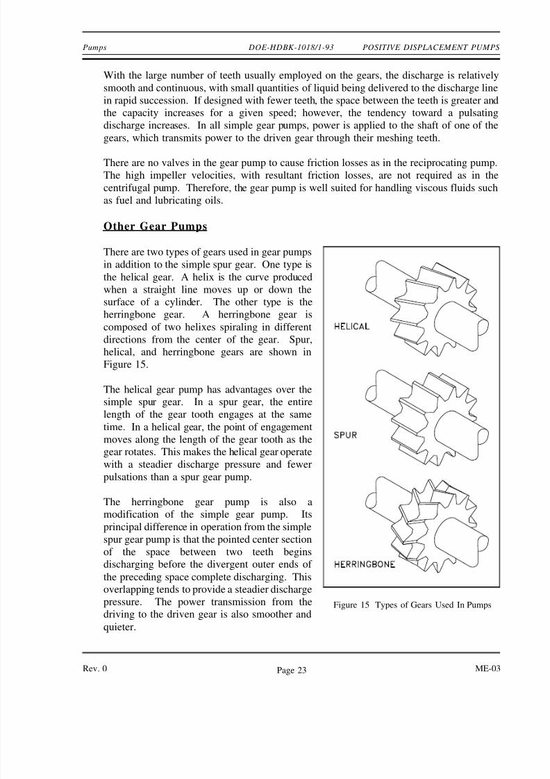
Other Gear Pumps
There are two types of gears used in gear pumps
Figure 15 Types of Gears Used In Pumps
in addition to the simple spur gear. One type is
the helical gear. A helix is the curve produced
when a straight line moves up or down the
surface of a cylinder. The other type is the
herringbone gear. A herringbone gear is
composed of two helixes spiraling in different
directions from the center of the gear. Spur,
helical, and herringbone gears are shown in
Figure 15.
The helical gear pump has advantages over the
simple spur gear. In a spur gear, the entire
length of the gear tooth engages at the same
time. In a helical gear, the point of engagement
moves along the length of the gear tooth as the
gear rotates. This makes the helical gear operate
with a steadier discharge pressure and fewer
pulsations than a spur gear pump.
The herringbone gear pump is also a
modification of the simple gear pump. Its
principal difference in operation from the simple
spur gear pump is that the pointed center section
of the space between two teeth begins
discharging before the divergent outer ends of
the preceding space complete discharging. This
overlapping tends to provide a steadier discharge
pressure. The power transmission from the
driving to the driven gear is also smoother and
quieter.
Rev. 0 ME-03Page 23
8/2/2019 Positive Disp Pump
http://slidepdf.com/reader/full/positive-disp-pump 7/11
POSITIVE DISPLACEMENT PUMPS DOE-HDBK-1018/1-93 Pumps
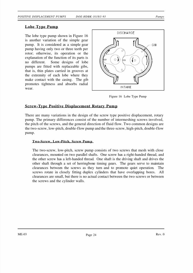
Lobe Type Pump
Figure 16 Lobe Type Pump
The lobe type pump shown in Figure 16
is another variation of the simple gear
pump. It is considered as a simple gear
pump having only two or three teeth perrotor; otherwise, its operation or the
explanation of the function of its parts is
no different. Some designs of lobe
pumps are fitted with replaceable gibs,
that is, thin plates carried in grooves at
the extremity of each lobe where they
make contact with the casing. The gib
promotes tightness and absorbs radial
wear.
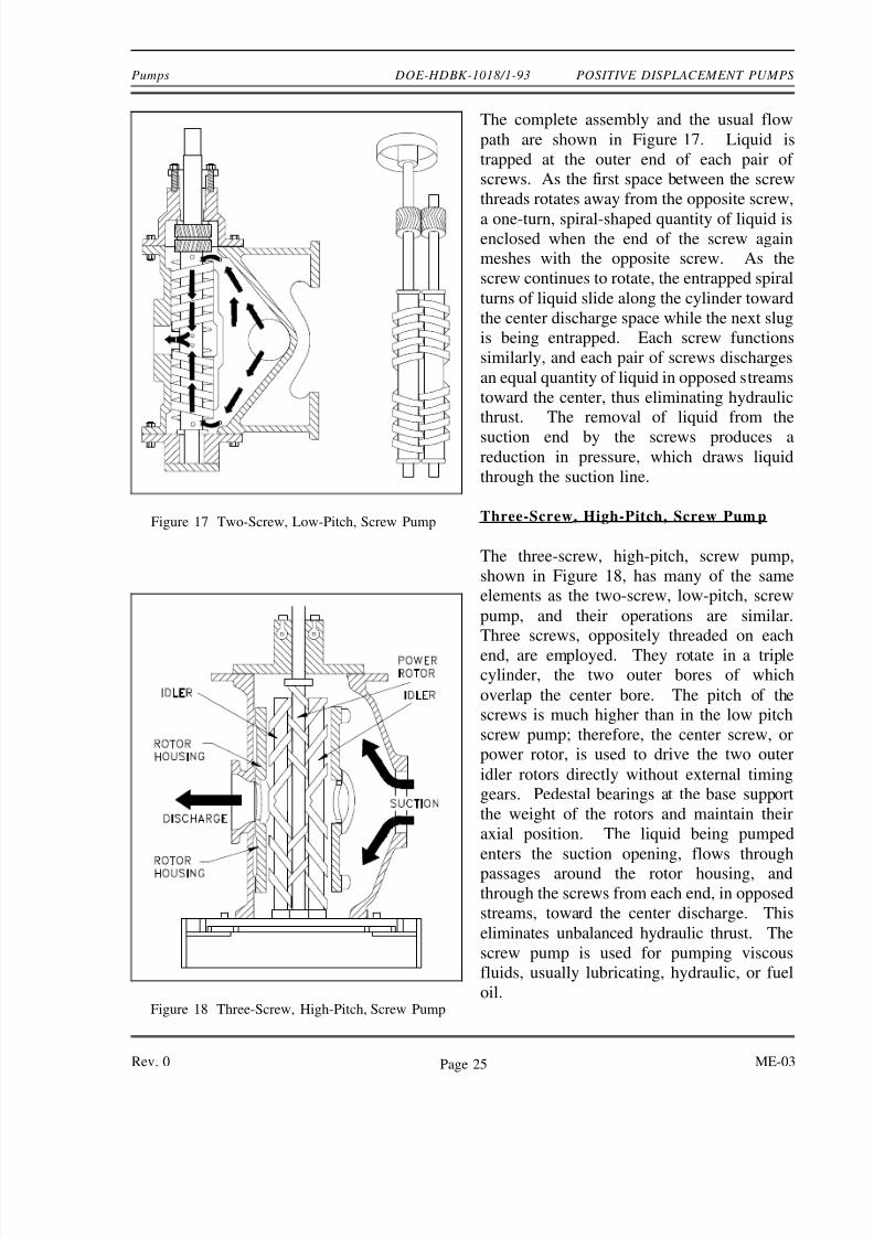
Screw-Type Positive Displacement Rotary Pump
There are many variations in the design of the screw type positive displacement, rotary
pump. The primary differences consist of the number of intermeshing screws involved,
the pitch of the screws, and the general direction of fluid flow. Two common designs are
the two-screw, low-pitch, double-flow pump and the three-screw, high-pitch, double-flow
pump.
Two-Screw, Low-Pitch, Screw Pump
The two-screw, low-pitch, screw pump consists of two screws that mesh with close
clearances, mounted on two parallel shafts. One screw has a right-handed thread, and
the other screw has a left-handed thread. One shaft is the driving shaft and drives the
other shaft through a set of herringbone timing gears. The gears serve to maintain
clearances between the screws as they turn and to promote quiet operation. The
screws rotate in closely fitting duplex cylinders that have overlapping bores. All
clearances are small, but there is no actual contact between the two screws or between
the screws and the cylinder walls.
ME-03 Rev. 0Page 24
8/2/2019 Positive Disp Pump
http://slidepdf.com/reader/full/positive-disp-pump 8/11
Pumps DOE-HDBK-1018/1-93 POSITIVE DISPLACEMENT PUMPS
The complete assembly and the usual flow
Figure 17 Two-Screw, Low-Pitch, Screw Pump
Figure 18 Three-Screw, High-Pitch, Screw Pump
path are shown in Figure 17. Liquid is
trapped at the outer end of each pair of
screws. As the first space between the screw
threads rotates away from the opposite screw,
a one-turn, spiral-shaped quantity of liquid isenclosed when the end of the screw again
meshes with the opposite screw. As the
screw continues to rotate, the entrapped spiral
turns of liquid slide along the cylinder toward
the center discharge space while the next slug
is being entrapped. Each screw functions
similarly, and each pair of screws discharges
an equal quantity of liquid in opposed streams
toward the center, thus eliminating hydraulic
thrust. The removal of liquid from the
suction end by the screws produces areduction in pressure, which draws liquid
through the suction line.
Three-Screw, High-Pitch, Screw Pump
The three-screw, high-pitch, screw pump,
shown in Figure 18, has many of the same
elements as the two-screw, low-pitch, screw
pump, and their operations are similar.
Three screws, oppositely threaded on each
end, are employed. They rotate in a triplecylinder, the two outer bores of which
overlap the center bore. The pitch of the
screws is much higher than in the low pitch
screw pump; therefore, the center screw, or
power rotor, is used to drive the two outer
idler rotors directly without external timing
gears. Pedestal bearings at the base support
the weight of the rotors and maintain their
axial position. The liquid being pumped
enters the suction opening, flows through
passages around the rotor housing, and
through the screws from each end, in opposed
streams, toward the center discharge. This
eliminates unbalanced hydraulic thrust. The
screw pump is used for pumping viscous
fluids, usually lubricating, hydraulic, or fuel
oil.
Rev. 0 ME-03Page 25
8/2/2019 Positive Disp Pump
http://slidepdf.com/reader/full/positive-disp-pump 9/11
POSITIVE DISPLACEMENT PUMPS DOE-HDBK-1018/1-93 Pumps
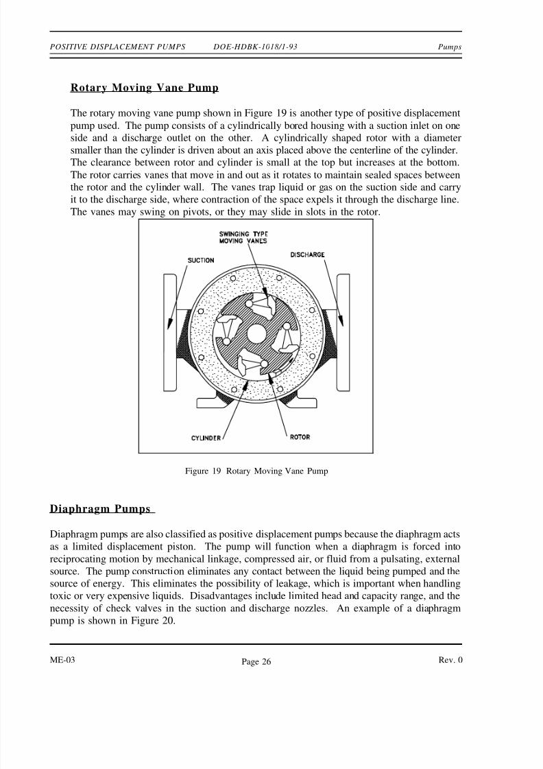
Rotary Moving Vane Pump
The rotary moving vane pump shown in Figure 19 is another type of positive displacement
pump used. The pump consists of a cylindrically bored housing with a suction inlet on one
side and a discharge outlet on the other. A cylindrically shaped rotor with a diametersmaller than the cylinder is driven about an axis placed above the centerline of the cylinder.
The clearance between rotor and cylinder is small at the top but increases at the bottom.
The rotor carries vanes that move in and out as it rotates to maintain sealed spaces between
the rotor and the cylinder wall. The vanes trap liquid or gas on the suction side and carry
it to the discharge side, where contraction of the space expels it through the discharge line.
The vanes may swing on pivots, or they may slide in slots in the rotor.
Figure 19 Rotary Moving Vane Pump
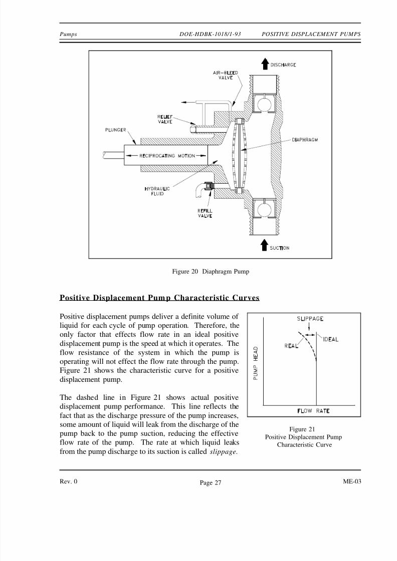
Diaphragm Pumps
Diaphragm pumps are also classified as positive displacement pumps because the diaphragm actsas a limited displacement piston. The pump will function when a diaphragm is forced into
reciprocating motion by mechanical linkage, compressed air, or fluid from a pulsating, external
source. The pump construction eliminates any contact between the liquid being pumped and the
source of energy. This eliminates the possibility of leakage, which is important when handling
toxic or very expensive liquids. Disadvantages include limited head and capacity range, and the
necessity of check valves in the suction and discharge nozzles. An example of a diaphragm
pump is shown in Figure 20.
ME-03 Rev. 0Page 26
8/2/2019 Positive Disp Pump
http://slidepdf.com/reader/full/positive-disp-pump 10/11
Pumps DOE-HDBK-1018/1-93 POSITIVE DISPLACEMENT PUMPS
Figure 20 Diaphragm Pump
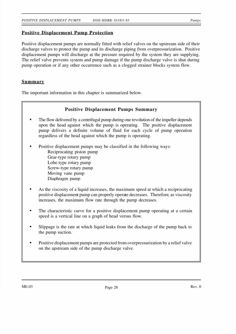
Positive Displacement Pump Characteristic Curves
Positive displacement pumps deliver a definite volume of
Figure 21
Positive Displacement Pump
Characteristic Curve
liquid for each cycle of pump operation. Therefore, the
only factor that effects flow rate in an ideal positive
displacement pump is the speed at which it operates. The
flow resistance of the system in which the pump is
operating will not effect the flow rate through the pump.
Figure 21 shows the characteristic curve for a positive
displacement pump.
The dashed line in Figure 21 shows actual positive
displacement pump performance. This line reflects the
fact that as the discharge pressure of the pump increases,
some amount of liquid will leak from the discharge of the
pump back to the pump suction, reducing the effective
flow rate of the pump. The rate at which liquid leaks
from the pump discharge to its suction is called slippage.
Rev. 0 ME-03Page 27
8/2/2019 Positive Disp Pump
http://slidepdf.com/reader/full/positive-disp-pump 11/11
POSITIVE DISPLACEMENT PUMPS DOE-HDBK-1018/1-93 Pumps
Positive Displacement Pump Protection
Positive displacement pumps are normally fitted with relief valves on the upstream side of their
discharge valves to protect the pump and its discharge piping from overpressurization. Positive
displacement pumps will discharge at the pressure required by the system they are supplying.
The relief valve prevents system and pump damage if the pump discharge valve is shut duringpump operation or if any other occurrence such as a clogged strainer blocks system flow.
Summary
The important information in this chapter is summarized below.
Positive Displacement Pumps Summary
The flow delivered by a centrifugal pump during one revolution of the impeller depends
upon the head against which the pump is operating. The positive displacement
pump delivers a definite volume of fluid for each cycle of pump operation
regardless of the head against which the pump is operating.
Positive displacement pumps may be classified in the following ways:
Reciprocating piston pump
Gear-type rotary pump
Lobe-type rotary pump
Screw-type rotary pump
Moving vane pumpDiaphragm pump
As the viscosity of a liquid increases, the maximum speed at which a reciprocating
positive displacement pump can properly operate decreases. Therefore, as viscosity
increases, the maximum flow rate through the pump decreases.
The characteristic curve for a positive displacement pump operating at a certain
speed is a vertical line on a graph of head versus flow.
Slippage is the rate at which liquid leaks from the discharge of the pump back to
the pump suction.
Positive displacement pumps are protected from overpressurization by a relief valve
on the upstream side of the pump discharge valve.
ME-03 Rev. 0Page 28

![Home []de sanctis" - paterno (ct) 9.15 disp. 3bp 3bl 3as ibl 4cl 2ap ibp 3dl 2bl disp. disp. iap 4bl 2dl 4al 3cl 3cp ven 10.15 2bl 2ap disp. ias disp- ibl 4cl 5dl 3bl iap 5el 4as 4dl](https://img.pdfslide.us/doc/110x75/610db2733385ae34c15bbc3c/home-de-sanctis-paterno-ct-915-disp-3bp-3bl-3as-ibl-4cl-2ap-ibp.jpg)