Embed Size (px)
Citation preview

TARABA JOURNAL OF ENGINEERING AND TECHNOLOGY (TAJET), FACULTY OF ENGINEERING, TARABA STATE UNIVERSITY, JALINGO. WWW.TAJET.COM.NG. ISSN: PRINT- 2636 7386; E- 2659 1278
6
Mshelia Y. P. et al , Positional Control of a Robotic Arm Using PWM Signals, TAJET 1(1),
June 2018: 6-11
Positional Control of a Robotic Arm Using PWM Signals
Y. P. Mshelia1, S. T. Yusuf 2, D. T. Agbu3, L. O. Agidike4
1, 2, 3, 4 Department of Electrical & Electronics Engineering, Taraba State University, Jalingo. Nigeria.
Introduction
A robotic arm can be defined as a robot manipulator, usually
programmable, with similar functions to a human arm. The links
of such a manipulator are connected by joints allowing either
rotational motion (such as in an articulated robot) or translational
(linear) displacement [1]. Robot Institute of America defines a
robot as: “A programmable multifunction manipulator designed
to move and manipulate material, parts, tools or specialized
devices through variable programmed motions for the
performance of a variety of specified tasks”. Robots are
indispensable in many manufacturing industries. The reason is
that the cost per hour to operate a robot is a fraction of the cost of
human labor needed to perform the same function. More than
this, once programmed, robots repeatedly perform functions with
a high accuracy that surpasses that of the most experienced
human operator. However, human operators are far more
versatile and can switch job tasks easily. Robots are built and
programmed to be job specific but as robots evolve with recent
developments in artificial intelligence, they will become more
versatile, emulating the human capacity and ability to switch job
tasks easily [2]. Robots play important roles in our lives and are
able to perform the tasks which cannot be done by humans in
terms of speed, accuracy and difficulty. They can be employed to
imitate human behaviors and then apply these behaviors to the
skills that allow the robot to achieve a certain task [3]. Robotics
is applied in different forms and fields to simulate human
behavior and motions [4] and this fact allows the workers to have
more free time to spend on skilled professions including the
programming, maintenance and operation of the robots which are
very essential [5].
The precise control of each degree of freedom of a robot arm
is a challenge in implementing industrial work. Many significant
researches are notable for controlling a robot arm. In this paper,
servo motors are used for robotic arm joint actuators and are
controlled by using PWM signals generated by the PIC 16F877A
microcontroller. Mikro C PRO is used to program the
microcontroller and control switches are used to input commands
to PIC microcontroller which is connected to robotic arm.
Analysis was carried out on the effects of PMW signals on the
angular displacement of servo motors. Robotic arm movement
can be done by moving to the left or right. The robotic arm will
be controlled via the controller and it will be able to grab, pick
up, move and place objects according to their weights and shape
in different places. The manipulator design is mostly expected to
pick up cubes and the geometric shapes like a box. This robotic
arm operates using 5 servo motors thus it has 5 Degree of
Freedom.
Design of Robotic Arm
The Robotic arm design involves mathematical modeling of
the kinematics, structure design, electronic design and software
design [6]. Inverse kinematics is used for the kinematic modeling
analysis algorithm and plastic sheets are recommended for the
structure design.
Robot arm kinematics deal with the analytical study of
geometry motion of robot arm from fixed reference of co-
ordinate system as a function of time without regard to
ARTICLE INFO
Art icle his tory:
Received: 1st May, 2018
Received in revised form:
30th May, 2018
Accepted: 6th June, 2018
Keywords
Microcontroller, PIC, Positional
control, Proteus 8.1, PWM, Robotic
arm.
ABSTRACT
The control of a robotic arm has been a challenge since earlier days of robotics.
This paper focuses on the control of a five axes articulated robotic arm using
servo motors. The robotic arm is controlled by a PIC 16F877A microcontroller
and its main function is to generate pulse width modulation (PWM) signals
applied to the servo motors for achieving the desired rotation angle. A PWM
signal could have different effects on various servo motors depending on their
specifications. Thus, it is important to apply the exact PWM signals to achieve
the rotation angle desired. Actual robotic arm has been designed using AutoCAD
and simulation was carried out on Proteus 8 Professional. A general formula was
derived for finding the pulse width required to achieve the desired rotation in
each servo motor. Experiments on the effects of PWM signals were undertaken
with actual servos. Simulation results were compared with experimental results
and discussed.
© 2018 TAJET. All rights reserved
6

TARABA JOURNAL OF ENGINEERING AND TECHNOLOGY (TAJET), FACULTY OF ENGINEERING, TARABA STATE UNIVERSITY, JALINGO. WWW.TAJET.COM.NG. ISSN: PRINT- 2636 7386; E- 2659 1278
7
Mshelia Y. P. et al , Positional Control of a Robotic Arm Using PWM Signals, TAJET 1(1),
June 2018: 6-11
movements that cause the motion. Articulated 5-DOF robotic arm
is designed by direct and inverse kinematic analysis methods [7].
Direct kinematics usually refers to home position of
geometric link parameters. It is used to find the position and
orientation of end effector with respect to the base with the help
of Denavit-Hartenberg algorithm used to obtain modeling
equations [7]. This method is not discussed in this paper.
Inverse kinematics usually refers to position and orientation
of end effector. It helps to find joint variables to achieve correct
position of source location part. In order to control the position
and orientation of end effector of a robotic arm to reach its object,
the inverse kinematic solution is more important. In this paper,
inverse kinematics problem is solved by geometric approach
method [7]. This method provides more insight to solving simple
manipulators with rotary joints.
The robotic arm has a total of five axes. Three major axes
which correspond to the base, shoulder and elbow are needed to
move the arm to the desired spot and two minor axes which
correspond to the gripper pitch and gripper spin. The design has
six rotary joints. Although we consider the number of joints as
five because two joints that move the shoulder, rotate in the same
direction with the same speed. Therefore they are counted as one
joint. Figure 1 shows the precise link coordinate diagram of axes
and joints [8].
Figure 1. Link coordinates of axes and joints of robot design.
The parameters and kinematic equations of the robotic arm
can be written as follows [8].
L0 to L5 – Six unit frames
𝑑5 – Gripper length
𝑞1 to 𝑞5 – Joint variables (𝑞 = 𝜃)
𝑃 – Gripper spin
𝑑1 – Height of shoulder from base
x0 to x5 – Motion of base, shoulder elbow, gripper pitch
and spin in x direction
y0 to y5 – Motion of base, shoulder elbow, gripper pitch
and spin in y direction
z0 to z5 – Motion of base, shoulder elbow, gripper pitch
and spin in z direction
1, 2, …, 5 – Rotary joints
𝑑2, 𝑑3, 𝑑4 – Link lengths
Base: 𝑞1= 𝜃1 (1)
Where: θ1= tan−1(𝑦0
𝑥0) and [−2𝜋 ≤ θ1≤ 2𝜋] for full clockwise and
counter clockwise rotation.
Shoulder:
𝑥𝑠ℎ𝑜𝑢𝑙𝑑𝑒𝑟 = √(𝑥1)2 + (𝑦1)2 (2)
𝑧𝑠ℎ𝑜𝑙𝑑𝑒𝑟 = 𝑧1 − 𝑑1 (3)
𝑥𝑠ℎ𝑜𝑢𝑙𝑑𝑒𝑟 = 𝑥𝑠ℎ𝑜𝑢𝑙𝑑𝑒𝑟 − 𝑑2 (4)
ℎ = √(𝑥𝑠ℎ𝑜𝑢𝑙𝑑𝑒𝑟)2 + (𝑧𝑠ℎ𝑜𝑜𝑢𝑙𝑑𝑒𝑟)2 (5)
where 𝜃2 = 𝑡𝑎𝑛−1 (𝑧𝑠ℎ𝑜𝑢𝑙𝑑𝑒𝑟
𝑥𝑠ℎ𝑜𝑢𝑙𝑑𝑒𝑟) − 𝑐𝑜𝑠−1 (
(𝐿𝑙)2+ (𝐿𝑢)2−ℎ2
2𝐿𝑙𝐿𝑢ℎ) and
[𝜋
6≤ 𝜃2 ≤
2𝜋
3]
For: (𝐿𝑙=Lower Link, 𝐿𝑢= Upper Link, ℎ = Height of shoulder
from base) for the rotation from 30° to 120°.
Elbow: 𝜃3 = 𝑐𝑜𝑠−1 ((𝐿𝑙)2+ (𝐿𝑢
2)− ℎ2
2𝐿𝑙𝐿𝑢ℎ) (6)
Where [7𝜋
6≤ 𝜃3 ≤
𝜋
3 ] , for the rotation 𝑓𝑟𝑜𝑚 60𝑜 𝑡𝑜 120𝑜.
Gripper Pitch: 𝜃5 = −𝜃2 − 𝜃3 (7)
Where: [−𝜋
4 ≤ 𝜃4 ≤
𝜋
4 ], for the rotation from −45𝑜 𝑡𝑜 45𝑜.
Gripper Spin: 𝜽𝟓 = 𝒄𝒐𝒔−𝟏 ((𝑳𝒍)𝟐+ (𝑳𝒖)𝟐−𝒉𝟐
𝟐𝑳𝒍𝑳𝒖𝒉) (8)
where: [−𝜋
4 ≤ 𝜃5 ≤
𝜋
4 ], for the rotation from −45𝑜 𝑡𝑜 45𝑜.
A model design of the robotic arm structure according to the
schematic and kinematic presentation was carried out using Auto
CAD design software. The model design is shown in figure 2.
7

TARABA JOURNAL OF ENGINEERING AND TECHNOLOGY (TAJET), FACULTY OF ENGINEERING, TARABA STATE UNIVERSITY, JALINGO. WWW.TAJET.COM.NG. ISSN: PRINT- 2636 7386; E- 2659 1278
8
Mshelia Y. P. et al , Positional Control of a Robotic Arm Using PWM Signals, TAJET 1(1),
June 2018: 6-11
Figure 2. Model Design of Robotic Structure as carried out using
Auto CAD
Electrical Circuit Design
The electrical circuit of a static robotic arm consists mainly
of the Joint Actuators (RC servo motors are used to move the
joints of robotic arm to achieve the desired position), the
Controller (this is achieved by PIC 16F877A microcontroller)
and the power supply.
Servo refers to an error sensing feedback control which is
used to correct the performance of a system. Servo or Radio
Controlled Servo Motors are DC motors equipped with a servo
mechanism for precise control of angular position. The RC servo
motors usually have a rotation limit from 90° to 180°. Servo
motor is a geared DC motor with positional feedback that allows
rotor to be positioned accurately [9]. Internally, a servo consists
of DC motor, potentiometer and control circuit as shown in figure
3.
Figure 3. Servo Motor and its components
The control circuitry compares an angular position,
determined by a control signal, to the current position of the
motor shaft as shown in figure 4. The motor shaft’s angular
position is often determined by a potentiometer, which is rotated
by the motor shaft. A potentiometer is a three terminal resistor,
whose center connection has variable resistance, usually
controlled by a slider or dial. The potentiometer acts as a variable
voltage divider. The voltage from the center connection of the
potentiometer represents the angular position the motor shaft is
in. The built-in controller generates an internal signal from the
voltage controlled by the potentiometer, compares it to the
control signal, and then provides power to the dc motor to rotate
the shaft in the appropriate direction to match the two. Servos
usually require a pulse-width modulated control signal [7]. PIC 16F877A microcontroller has 40 pins and is a popular
microcontroller capable of doing complex tasks. This
microcontroller has 8192 × 14 flash program memory which
consists of 368 bytes of RAM and 256 bytes of non-volatile
EEPROM memory. 33 pins are dedicated for input/output pins
and 8 multiplexed analog/digital converters with 10 bits
resolution. This microcontroller also has specifications such as
PWM generator, 3 timers, analog capture and comparator circuit,
universal synchronous receiver transmitter (USART), internal
and external interrupt capabilities. The operating voltage for the
microcontroller is 2.0V to 5.56V DC and operates at an external
oscillator frequency in the range of 0Hz to 20Hz. Figure 5 shows
the pin configuration of the PIC 16F877A microcontroller and
the pins which are used for PWM generation are marked [9].
Figure 4. Signal flow diagram of the control circuitry of a servo
motor
8
TARABA JOURNAL OF ENGINEERING AND TECHNOLOGY (TAJET), FACULTY OF ENGINEERING, TARABA STATE UNIVERSITY, JALINGO. WWW.TAJET.COM.NG. ISSN: PRINT- 2636 7386; E- 2659 1278
9
Mshelia Y. P. et al , Positional Control of a Robotic Arm Using PWM Signals, TAJET 1(1),
June 2018: 6-11
Figure 5. PIC 16F877A pin configuration
Software Design
There are variety of programming languages and compilers
such as Assembly, BASIC, PASCAL, C and C++. Onboard
software is mainly developed with micro C[10]. This software
interfaces between the PIC microcontroller and the PC In this
paper, Mikro C PRO for PIC compiler (C language) is used to
generate HEX files for programming the microcontroller. When
the HEX code is ready, it can be written on the EPROM of the
microcontroller using a PIC-programmer device such as PIC-kit
3, PIC-kit 2, NUP 133 etc.
Implementation
As seen in figure 6, each servo motor was operated manually
with two buttons for rotation and automatically controlled with
two buttons. Each input control button causes the microcontroller
to generate the necessary PWM signal and send it to the
corresponding servo motor. The servo motor which was
responsible for the rotation of the base (S1) was connected to Port
D.0 of the microcontroller. Two servos which are responsible for
the motion of the shoulder (S2 and S3) were connected to Port
D.1 of the microcontroller. The servo motor responsible for the
rotation of the elbow (S4) was connected to Port D.2 of the
microcontroller. The servo motor for the gripper pitch (S5) is
connected to Port D.3 of the microcontroller. The corresponding
servo motor for the gripper spin (S6) was connected to the Port
D.4 and the gripper servo (S7) was connected to Port D.5 which
was responsible for opening and closing the end-effector.
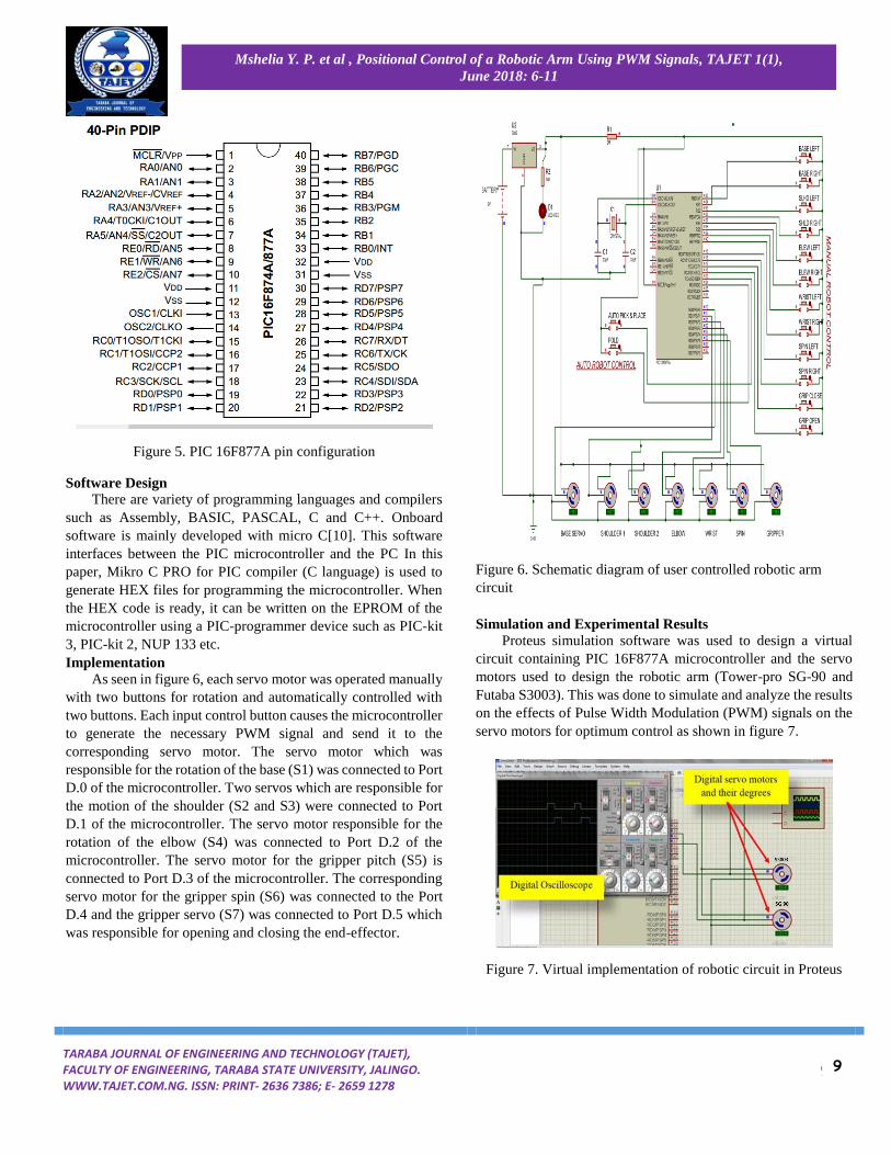
Figure 6. Schematic diagram of user controlled robotic arm
circuit
Simulation and Experimental Results
Proteus simulation software was used to design a virtual
circuit containing PIC 16F877A microcontroller and the servo
motors used to design the robotic arm (Tower-pro SG-90 and
Futaba S3003). This was done to simulate and analyze the results
on the effects of Pulse Width Modulation (PWM) signals on the
servo motors for optimum control as shown in figure 7.
Figure 7. Virtual implementation of robotic circuit in Proteus
9

TARABA JOURNAL OF ENGINEERING AND TECHNOLOGY (TAJET), FACULTY OF ENGINEERING, TARABA STATE UNIVERSITY, JALINGO. WWW.TAJET.COM.NG. ISSN: PRINT- 2636 7386; E- 2659 1278
10
Mshelia Y. P. et al , Positional Control of a Robotic Arm Using PWM Signals, TAJET 1(1),
June 2018: 6-11
An experimental circuit of the robotic arm was also
implemented on a proto/bread board as shown in figure 8 to test
the effects of PWM signals on actual servo motors and to
compare the results obtained in the experiments to the simulation
results.
Figure 8. Experimental implementation of robotic arm circuit
Since there are two types of servos with different
specifications in the robotic arm design, the results obtained
differ in terms of pulse width, angle and the general servo motor
behavior. A protractor was used to measure the angle of rotation
and an oscilloscope was used to measure the pulse width if the
signals as shown in figure 9.
According to Tables 1 and 2, the experimental circuit and
simulation considers the rotation angle with respect to the
generated pulses with the pulse width ranges from 600µs to
2400µs for Futaba S3003 and from 400µs to 2400µs for Tower-
Pro SG-90 servo.
Figure 9. Measuring the pulse width of signals for Servo control
Table 1. Data obtained for Tower Pro SG-90 servo motor
Simulation
Results
Experimental
Results
Results from
derived equation
PWM
(µs)
Angle
(°) PWM
(µs)
Angle
(°) PWM
(µs)
Angle
(°) 450 -85.4 450 -85.6 451.11 -85.50
675 -65.2 675 -65.0 675.55 -65.25
1287 -10.1 1287 -10.0 1287.77 -10.17
1576 +15.9 1576 +16.0 1576.66 +15.84
2070 +60.4 2070 +60.5 2071.11 +60.30
2222 +74.1 2222 +74.0 2223.33 +73.98
Table 2. Data obtained for Futaba S3003 servo motor
Simulation
Results
Experimental
Results
Results from
derived equation
PWM
(µs)
Angle
(°) PWM
(µs)
Angle
(°) PWM
(µs)
Angle
(°) 600 -89.9 600 -90.0 601 -90.0
675 -82.4 675 -82.6 676 -82.5
1287 -21.2 1287 -21.3 1288 -21.3
1576 +07.7 1576 +07.8 1577 +07.6
2070 +57.1 2070 +57.0 2071 +57.0
2222 +72.3 2222 +72.1 2223.33 +72.2
Figure 10 shows a graphical representation of the results obtained
relating the PWM signals to the corresponding angles. The
rotation degree is considered from -90° to +90° as the
specifications of the servo motors suggest.
Figure 10. Graph of servo motor angles against applied pulses
Observations
1. From Table 1, the comparison of simulated, experimental
and calculated results for SG-90 servo shows that:
10

TARABA JOURNAL OF ENGINEERING AND TECHNOLOGY (TAJET), FACULTY OF ENGINEERING, TARABA STATE UNIVERSITY, JALINGO. WWW.TAJET.COM.NG. ISSN: PRINT- 2636 7386; E- 2659 1278
11
Mshelia Y. P. et al , Positional Control of a Robotic Arm Using PWM Signals, TAJET 1(1),
June 2018: 6-11
i. For PWM signal (P) a difference of 0.45 𝜇𝑠 to
1.45 𝜇𝑠 was presented.
ii. For rotation Angle (𝜃) of the servo motor a
difference of 0.05° to 0.25° was presented.
2. From Table 2, the comparison of simulated, experimental
and calculated results for S3003 shows that:
i. For PWM signal (P) a difference of 1 𝜇𝑠 to 2 𝜇𝑠 was
presented.
ii. For rotation Angle (𝜃) of the servo motor a
difference of 0.1° to 0.3° was presented.
3. As seen in the Tables 1 and 2, both servos have a stable
response to their PWM signals. Thus, rotation angle of the
servo motors increases proportionally to increase of the
PWM signals.
4. By considering the accuracy and comparisons of the
experimental and simulation results, a general formula for
any servo can be derived to find the required PWM input
signal as shown in Eq. 9.
𝑃𝑥 = ((𝜃+(
𝜀
2)
𝜀) (𝑃𝑚 − 𝑃𝑜)) − 𝑃𝑂 (9)
For: −90 < 𝜃 < +90
where 𝑃𝑥 is the Pulse Width signal required, 𝜃 is the Angle
required, 𝜀 is the maximum rotation angle range of servo. 𝑃𝑚 is
the maximum Pulse width required by servo motor, 𝑃𝑜 is the
minimum Pulse width required by servo motor.
The accuracy of the proposed formula can be obtained as
almost 96%, meaning that the rotation of the servo can possibly
have 4% error comparing to the expectations.
Conclusion In this paper, the procedure of designing and controlling an
articulated robotic arm using a microcontroller and servo motors
with the help of PWM signals were discussed, the effect of these
pulses on the servo motors using software simulation and actual
experimentation were discussed. A general formula which
facilitates the design and motion control of the robotic arm has also
been proposed.
As the future work of a developed robotic arm using artificial
intelligence (AI), a voice-controlled robot can be considered
where the user can simply control the robot by giving voice
commands such as giving directions (up, down, left, right) and
actions (grasp, drop, rotate left, and rotate right). Increasing the
degrees of freedom of the robotic arm by implanting more servo
motors for flexibility and equipping the robotic arm with
proximity sensors can be considered. Developing a graphical user
interface for making the arm more user friendly and developing
a web interface so that arm could be controlled in remote places
by a web browser.
References
[1] Ovy, E. G., Seraji, S., Ferdous, S. M. and
Rokonuzzaman, M. (2011). A Novel Design of an ATmega32L
Microcontroller Based Controller Circuit for the Motion Control
of a Robot Arm Actuated by DC Motors, Cyber Journals:
Multidisciplinary Journals in Science and Technology, Journal of
Selected Areas in Robotics and Control (JSRC), April Edition.
[2] Ishak, S. H. (2011). Design of Robotic Arm Controller
Using Matlab, Malaysia.
[3] Lin, I. H., Liu, C. Y. and Chen L. C. (2011). Evaluation
of Human-Robot Arm Movement Imitation, Proceedings of 8th
Asian Control Conference (ASCC), 287 – 292.
[4] Nikku S. (2011). Introduction to Robotics, USA: John
Wiley & Sons.
[5] http://www.robotics.org/content-detail.cfm/ Industrial-Robotics-FeaturedArticles/How-Robots-Will-Affect-Future-Generations/content_id/834 Date of search: 28/02/2018
[6] Nones Y. A. (2003). Heterogeneous Modeling and
Design of a Robot Arm Control System, Illinois Tech Robotics
(ITR), 1 - 6.
[7] Patil, S. and Lakshminarayan, S. (2012). Position
Control of Pick and Place Robotic Arm, EIE 2nd International
Conference on Computers, Energy, Networking, Robotics and
Telecom.
[8] Seki, K., Yokoi H. and Iwasaki M. (2012). Experimental
Evaluations of Friction Behavior in Micro-Displacement Region
Positioning for Servo Motor with Air Bearings, Proceeding of
IEEE International Conference on Advanced Intelligent
Mechatronics, 731 – 736.
[9] Ibrahim, D. (2006). 30 Projects Using PIC Basic and
PIC Basic Pro, UK: MPG books Ltd.
[10] Nair, S. R. and Nair, S. R. (2012). Design of a Voice
Controlled Robotic Arm for Picking and Placing an Object, IOSR
Journal of Engineering, Vol. 2(4), 670 – 673.
11