Embed Size (px)
Citation preview

SENSORS & TRANSDUCERS
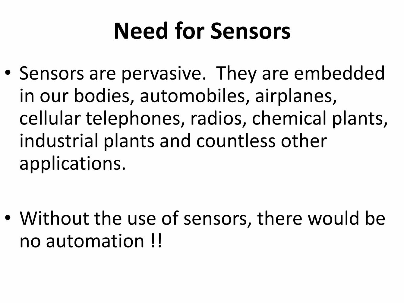
Need for Sensors
• Sensors are pervasive. They are embedded in our bodies, automobiles, airplanes, cellular telephones, radios, chemical plants, industrial plants and countless other applications.
• Without the use of sensors, there would be no automation !!
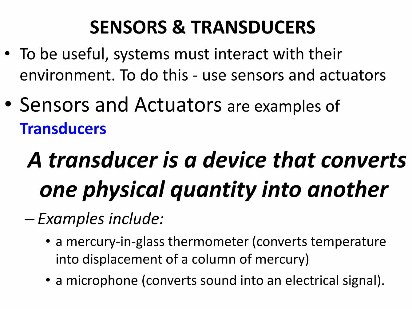
SENSORS & TRANSDUCERS
• To be useful, systems must interact with their environment. To do this - use sensors and actuators
• Sensors and Actuators are examples of
Transducers
A transducer is a device that converts one physical quantity into another
– Examples include: • a mercury-in-glass thermometer (converts temperature
into displacement of a column of mercury)
• a microphone (converts sound into an electrical signal).
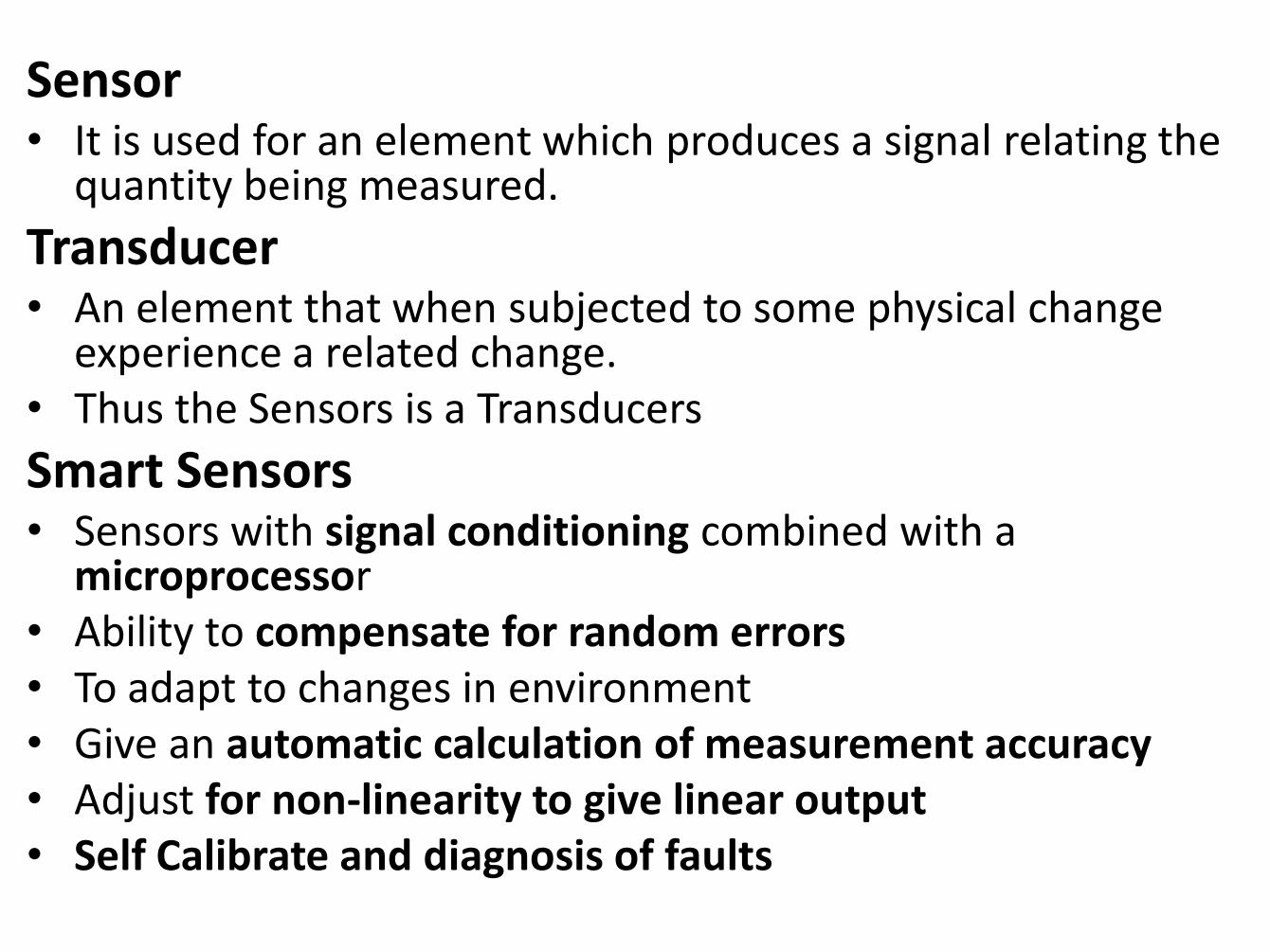
Sensor • It is used for an element which produces a signal relating the
quantity being measured.
Transducer • An element that when subjected to some physical change
experience a related change. • Thus the Sensors is a Transducers
Smart Sensors • Sensors with signal conditioning combined with a
microprocessor • Ability to compensate for random errors • To adapt to changes in environment • Give an automatic calculation of measurement accuracy • Adjust for non-linearity to give linear output • Self Calibrate and diagnosis of faults
• The function of the sensor (or) transducer is to sense (or) detect a parameter such as pressure, temperature, flow, motion, resistance, voltage, current and power.
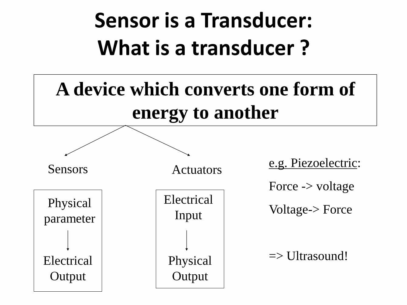
Sensor is a Transducer: What is a transducer ?
A device which converts one form of
energy to another
Actuators Sensors
Physical
parameter
Electrical
Output
Electrical
Input
Physical
Output
e.g. Piezoelectric:
Force -> voltage
Voltage-> Force
=> Ultrasound!
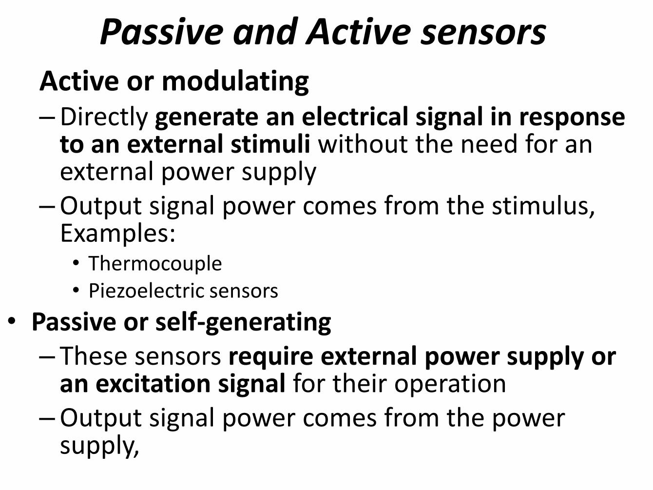
Passive and Active sensors Active or modulating –Directly generate an electrical signal in response
to an external stimuli without the need for an external power supply
–Output signal power comes from the stimulus, Examples: • Thermocouple • Piezoelectric sensors
• Passive or self-generating – These sensors require external power supply or
an excitation signal for their operation –Output signal power comes from the power
supply,
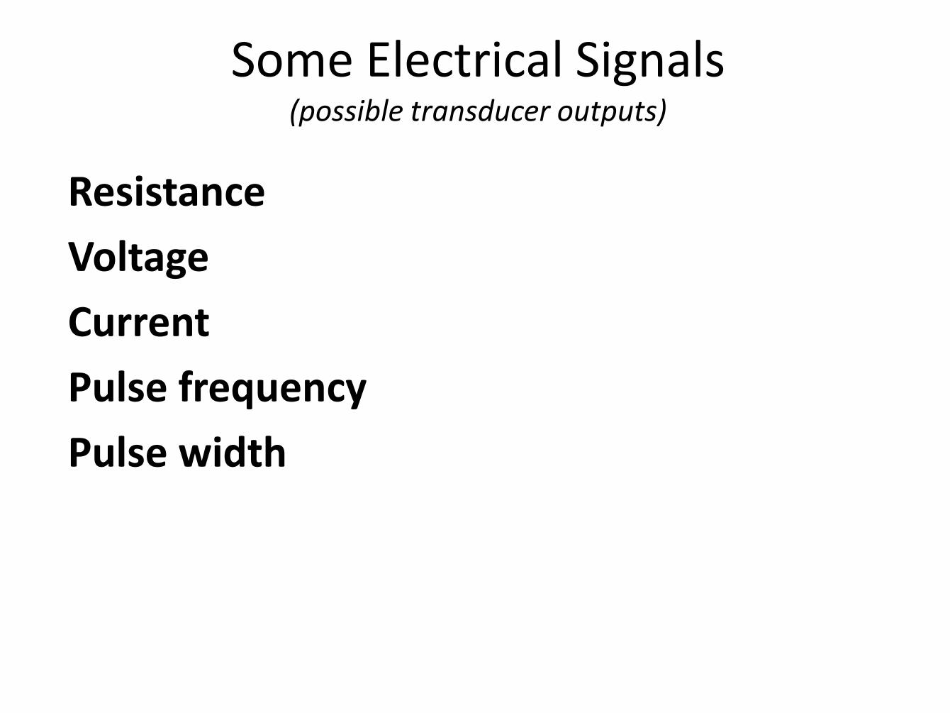
Resistance
Voltage
Current
Pulse frequency
Pulse width
Some Electrical Signals (possible transducer outputs)
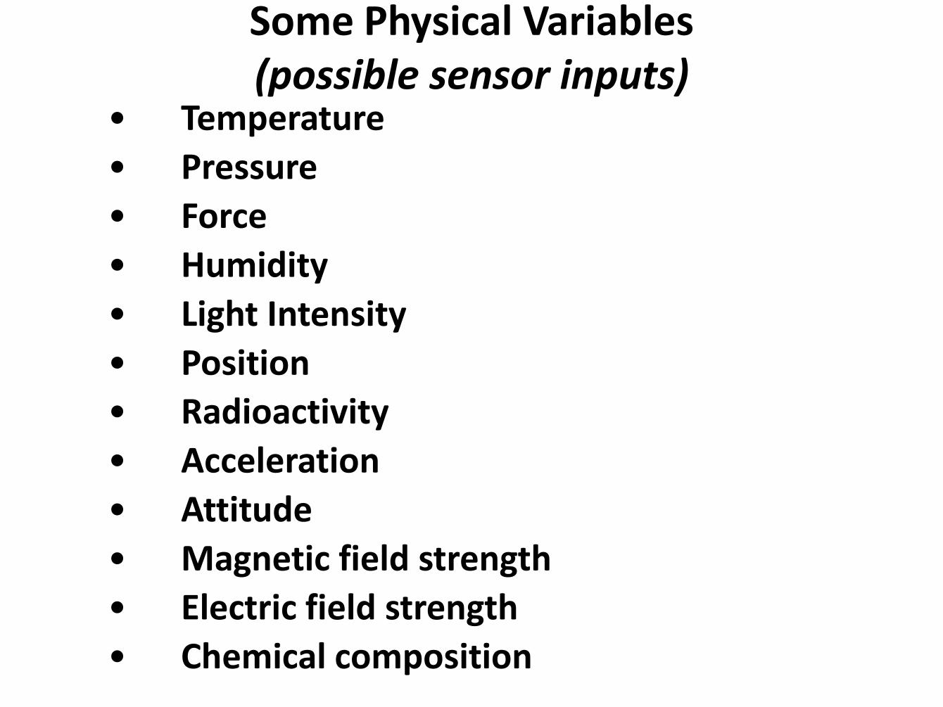
• Temperature
• Pressure
• Force
• Humidity
• Light Intensity
• Position
• Radioactivity
• Acceleration
• Attitude
• Magnetic field strength
• Electric field strength
• Chemical composition
Some Physical Variables (possible sensor inputs)
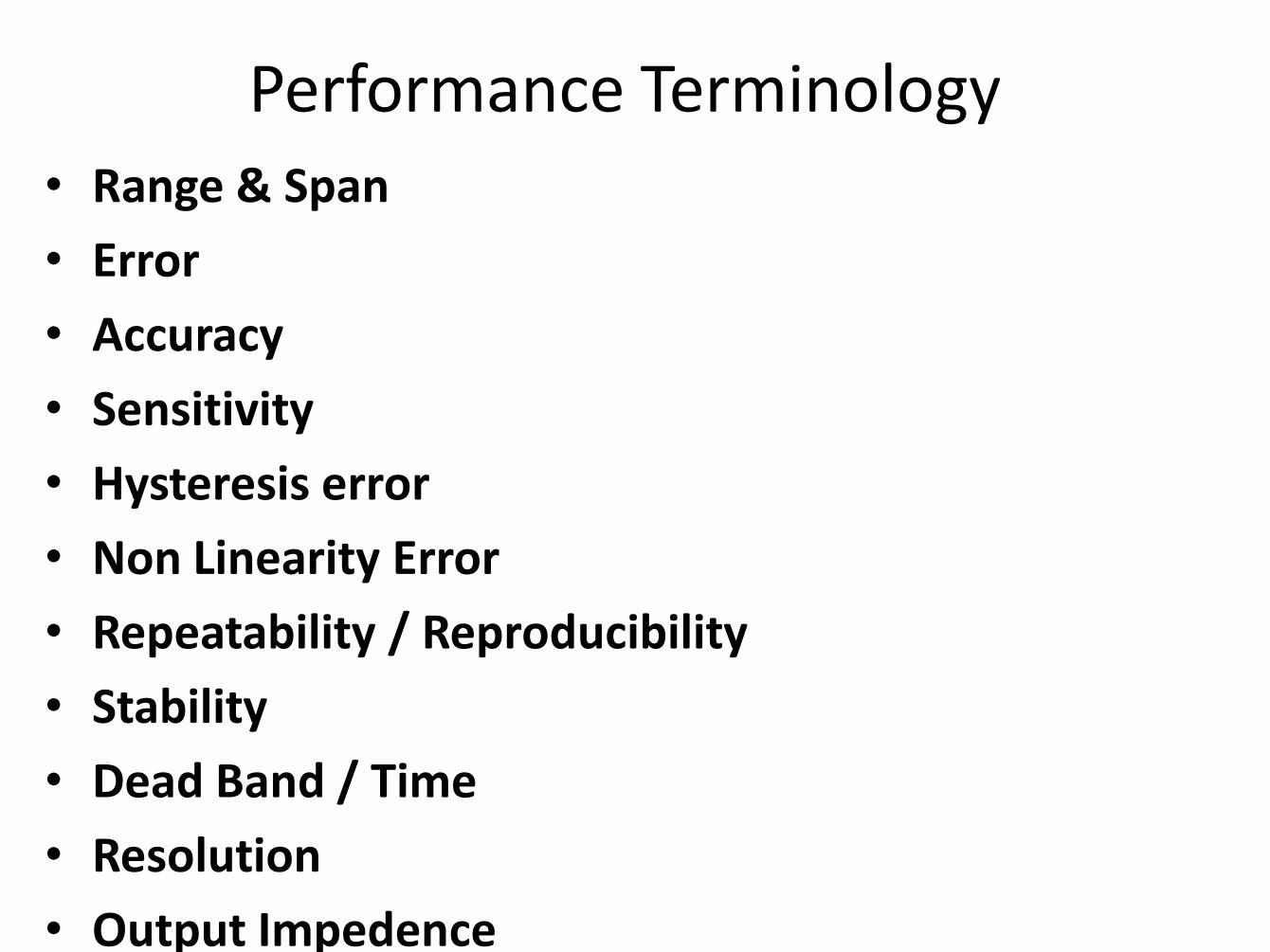
Performance Terminology
• Range & Span
• Error
• Accuracy
• Sensitivity
• Hysteresis error
• Non Linearity Error
• Repeatability / Reproducibility
• Stability
• Dead Band / Time
• Resolution
• Output Impedence
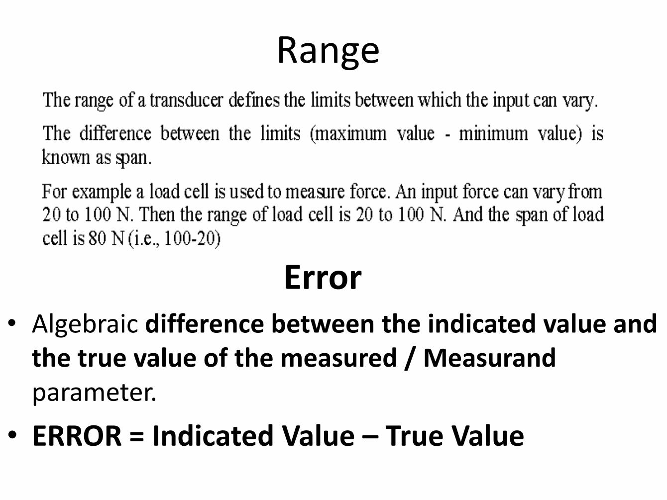
Range
• Algebraic difference between the indicated value and the true value of the measured / Measurand parameter.
• ERROR = Indicated Value – True Value
Error
Accuracy +/-5% of full range output, for a
Range of 0-200,it is +/- 10 degree C
A measure of the lack of random errors (scatter)- Precision
Accuracy Vs Precision
Accuracy vs Precision
• Accuracy is how close an individual value is to the true or accepted value
• Precision is the consistency of a series of measurements
From Basic Laboratory Methods for Biotechnology: Textbook and Laboratory Reference, Seidman and Moore,
2000
Measurements can be:
• Accurate and precise (best)
• Accurate and imprecise (user error)
• Inaccurate but precise (instrument error)
• Inaccurate and imprecise
Expressions
• Accuracy – % error = True value – measured value X 100%
True value
Precision – Expression of variability
– Take the mean (average)
– Calculate how much each measurement deviates from mean
– Take an average of the deviation, so it is the average deviation from the mean
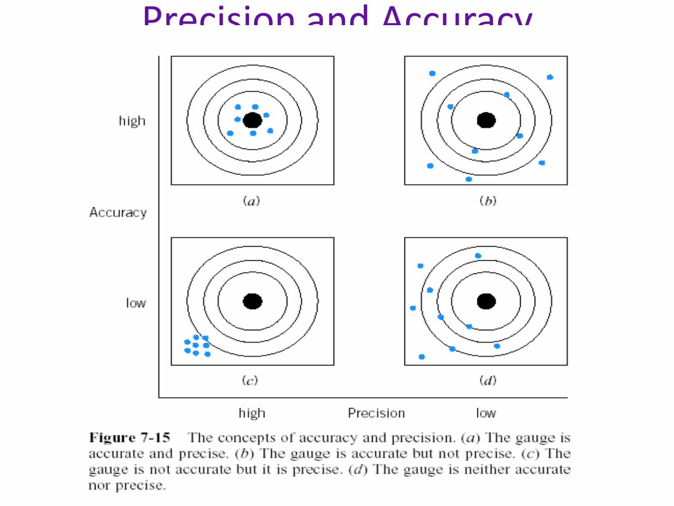
Precision and Accuracy
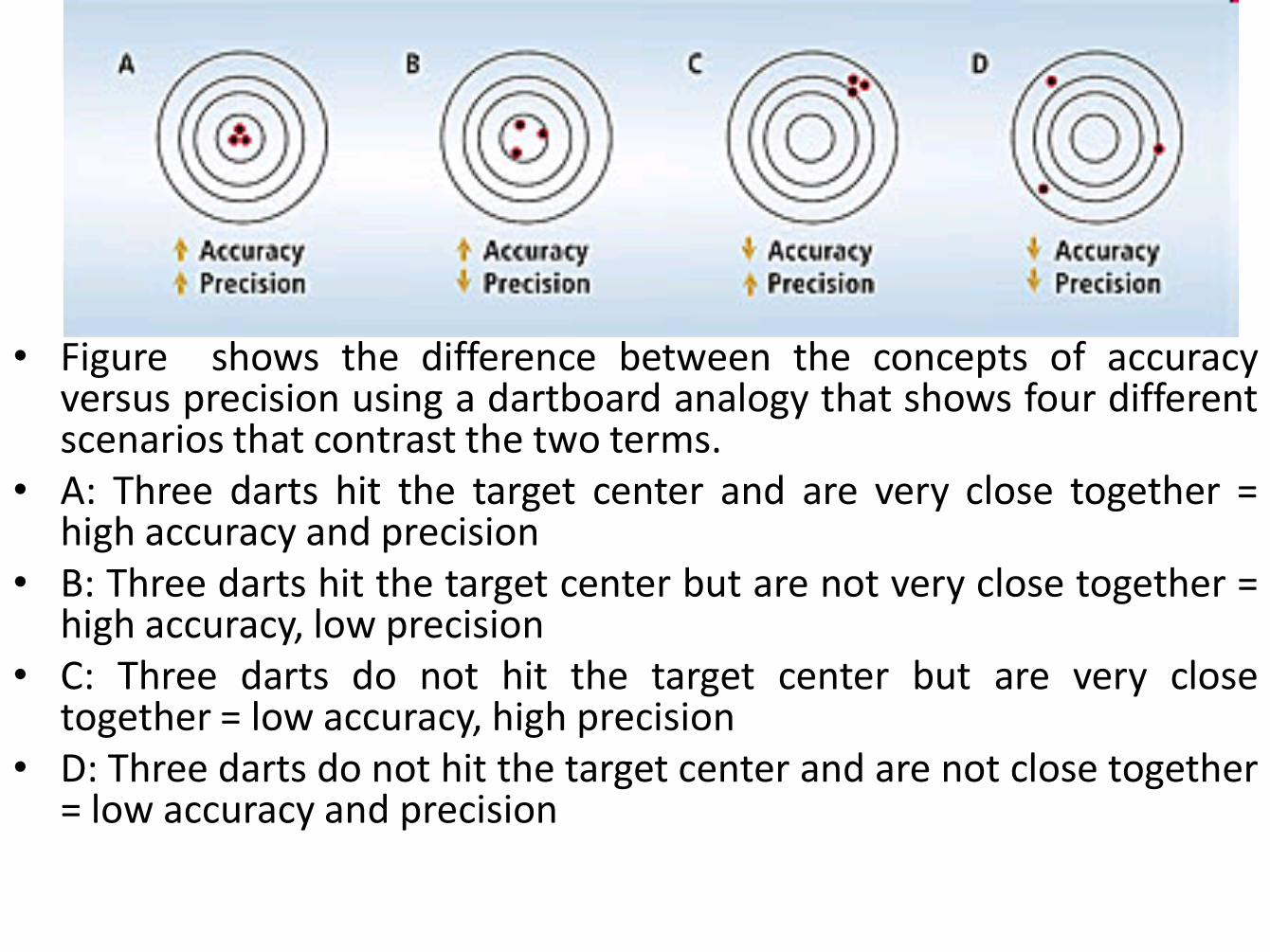
• Figure shows the difference between the concepts of accuracy versus precision using a dartboard analogy that shows four different scenarios that contrast the two terms.
• A: Three darts hit the target center and are very close together = high accuracy and precision
• B: Three darts hit the target center but are not very close together = high accuracy, low precision
• C: Three darts do not hit the target center but are very close together = low accuracy, high precision
• D: Three darts do not hit the target center and are not close together = low accuracy and precision
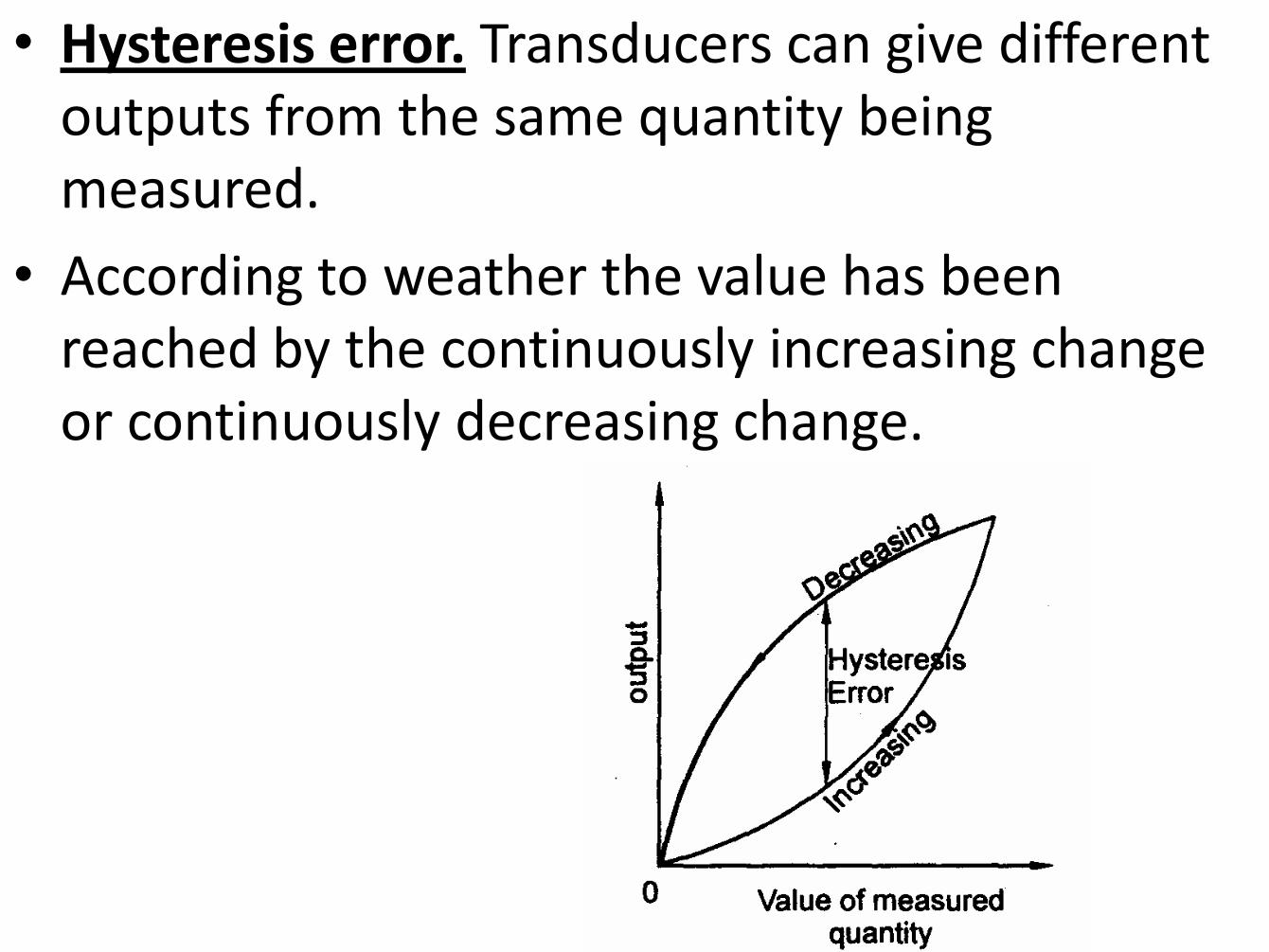
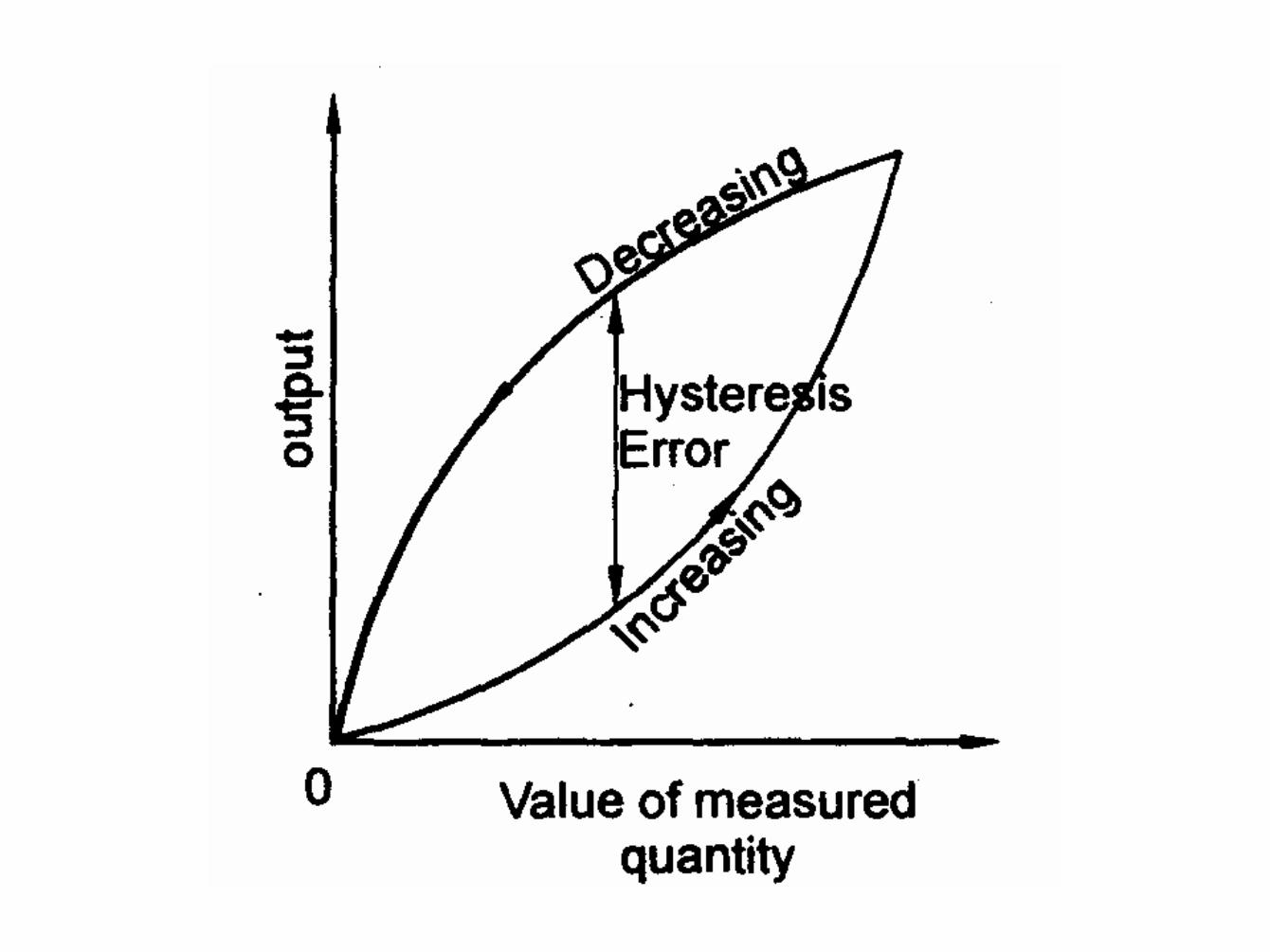
• Hysteresis error. Transducers can give different outputs from the same quantity being measured.
• According to weather the value has been reached by the continuously increasing change or continuously decreasing change.
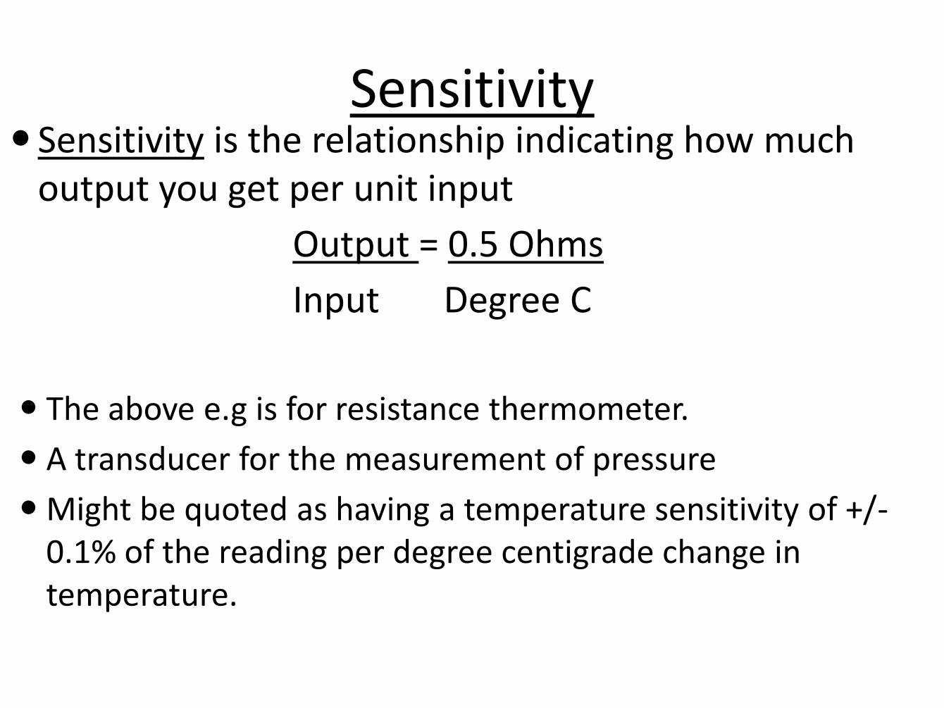
Sensitivity is the relationship indicating how much output you get per unit input
Output = 0.5 Ohms
Input Degree C
The above e.g is for resistance thermometer.
A transducer for the measurement of pressure
Might be quoted as having a temperature sensitivity of +/-0.1% of the reading per degree centigrade change in temperature.
Sensitivity
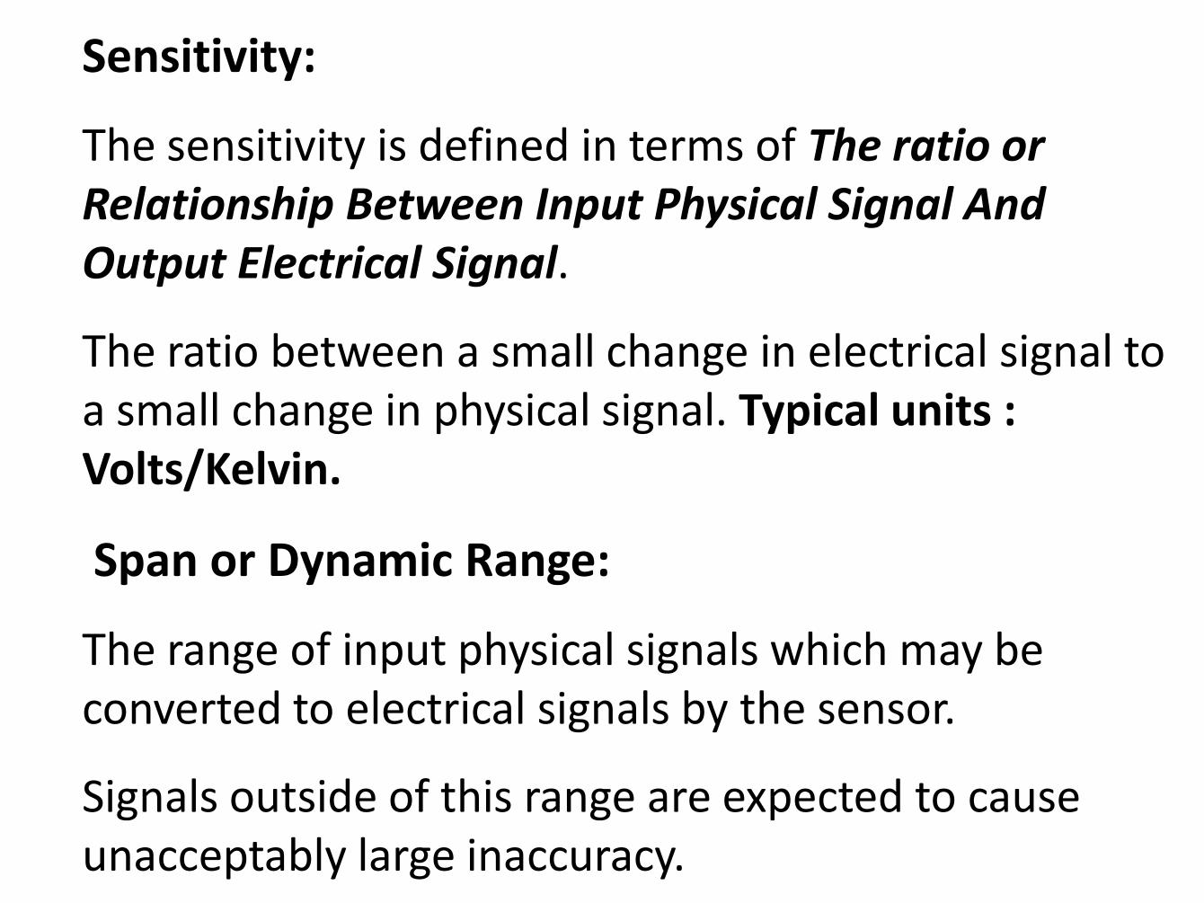
Sensitivity:
The sensitivity is defined in terms of The ratio or Relationship Between Input Physical Signal And Output Electrical Signal.
The ratio between a small change in electrical signal to a small change in physical signal. Typical units : Volts/Kelvin.
Span or Dynamic Range:
The range of input physical signals which may be converted to electrical signals by the sensor.
Signals outside of this range are expected to cause unacceptably large inaccuracy.
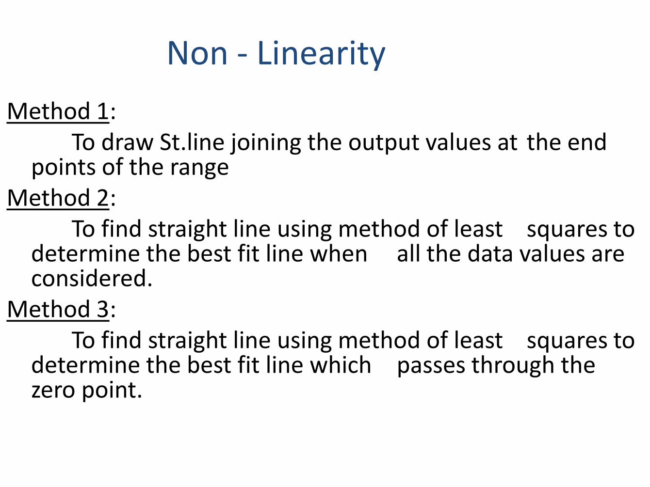
Method 1: To draw St.line joining the output values at the end
points of the range Method 2: To find straight line using method of least squares to
determine the best fit line when all the data values are considered.
Method 3: To find straight line using method of least squares to
determine the best fit line which passes through the zero point.
Non - Linearity
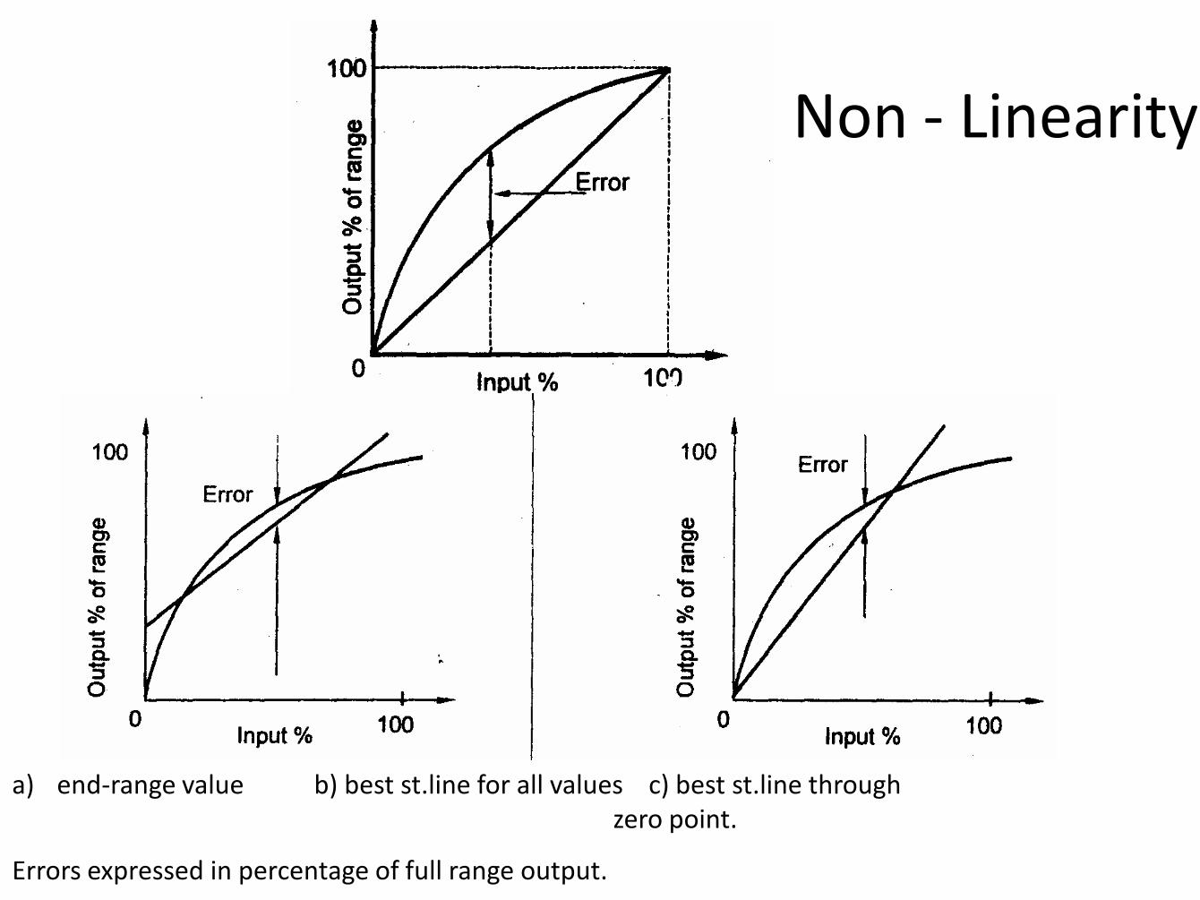
Non - Linearity
a) end-range value b) best st.line for all values c) best st.line through zero point.
Errors expressed in percentage of full range output.
• Repeatability /Reproducibility The ability of the sensor to give same output for the repeated
application of the same input value. Repeatability =(max-min values given)/Full range
• Stability The stability of a transducer is its ability to given the same
output when used to measure a constant input over a period of time.
The term drift is often used to describe the change in output
that occurs over time.
• Drift expressed in full range output.
• Zero Drift means if there is change in output when there is zero input.
Dead band /Time:
The dead band or dead space of a transducer is the range of input values for which there is no output.
The length of time from the application of an input until the output begins to respond and change.
Output Impedance:
Sensor giving an electrical output is interfaced with an electronic circuit it is necessary to know the output impedance.
This impedance is connected in either series or parallel with that circuit.
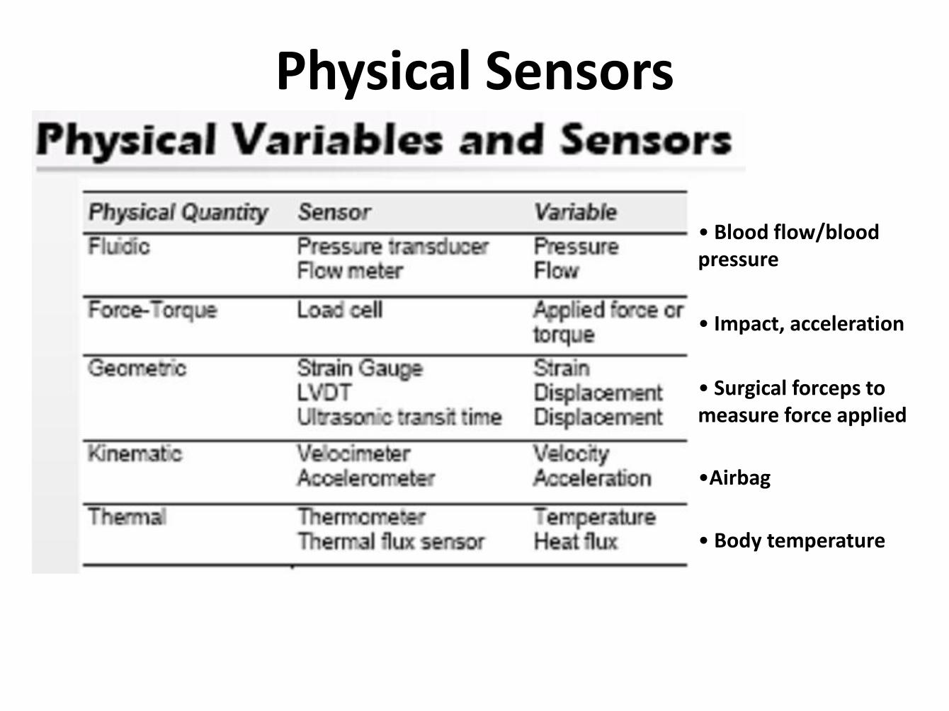
Physical Sensors
• Blood flow/blood pressure
• Impact, acceleration
• Surgical forceps to measure force applied
•Airbag
• Body temperature
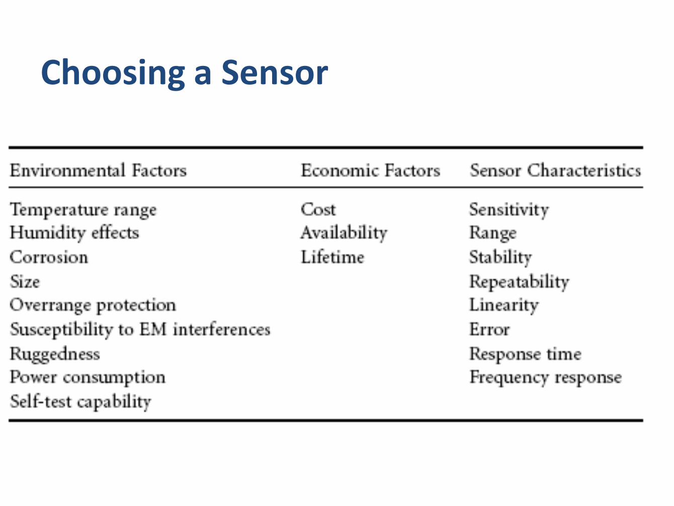
Choosing a Sensor
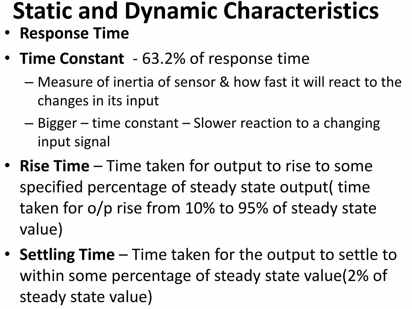
Static and Dynamic Characteristics • Response Time
• Time Constant - 63.2% of response time
– Measure of inertia of sensor & how fast it will react to the changes in its input
– Bigger – time constant – Slower reaction to a changing input signal
• Rise Time – Time taken for output to rise to some specified percentage of steady state output( time taken for o/p rise from 10% to 95% of steady state value)
• Settling Time – Time taken for the output to settle to within some percentage of steady state value(2% of steady state value)
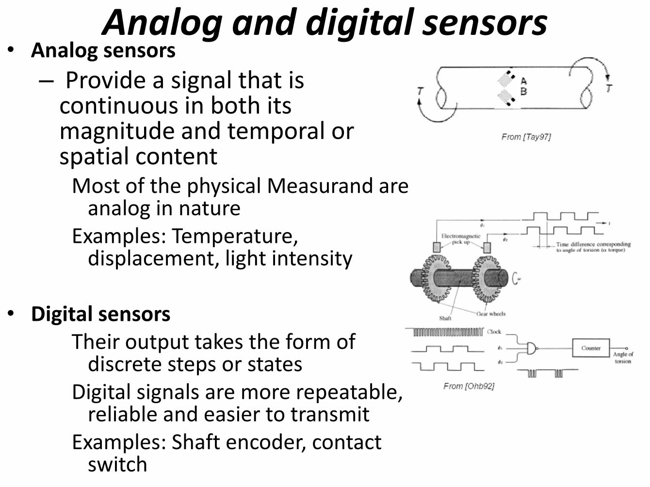
Analog and digital sensors
• Analog sensors
– Provide a signal that is continuous in both its magnitude and temporal or spatial content
Most of the physical Measurand are analog in nature
Examples: Temperature, displacement, light intensity
• Digital sensors
Their output takes the form of discrete steps or states
Digital signals are more repeatable, reliable and easier to transmit
Examples: Shaft encoder, contact switch
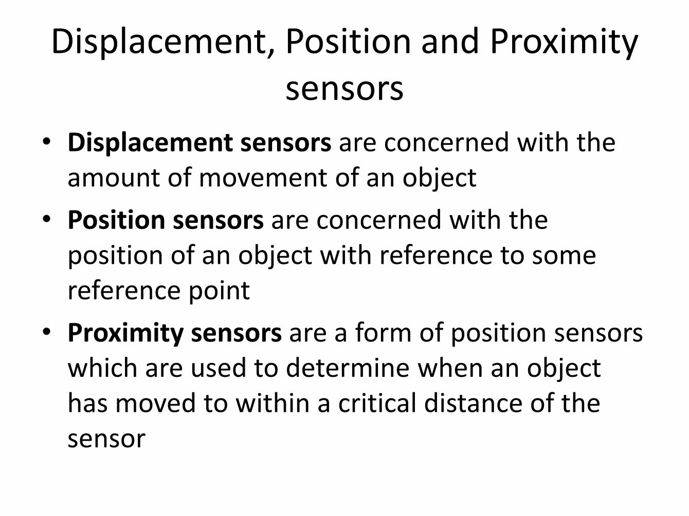
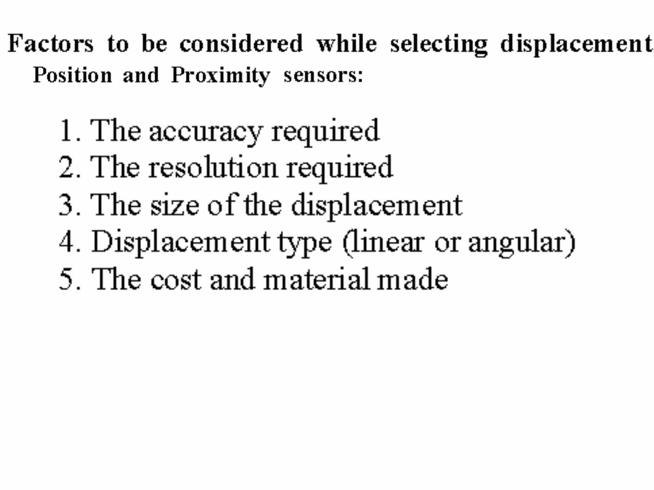
Displacement, Position and Proximity sensors
• Displacement sensors are concerned with the amount of movement of an object
• Position sensors are concerned with the position of an object with reference to some reference point
• Proximity sensors are a form of position sensors which are used to determine when an object has moved to within a critical distance of the sensor
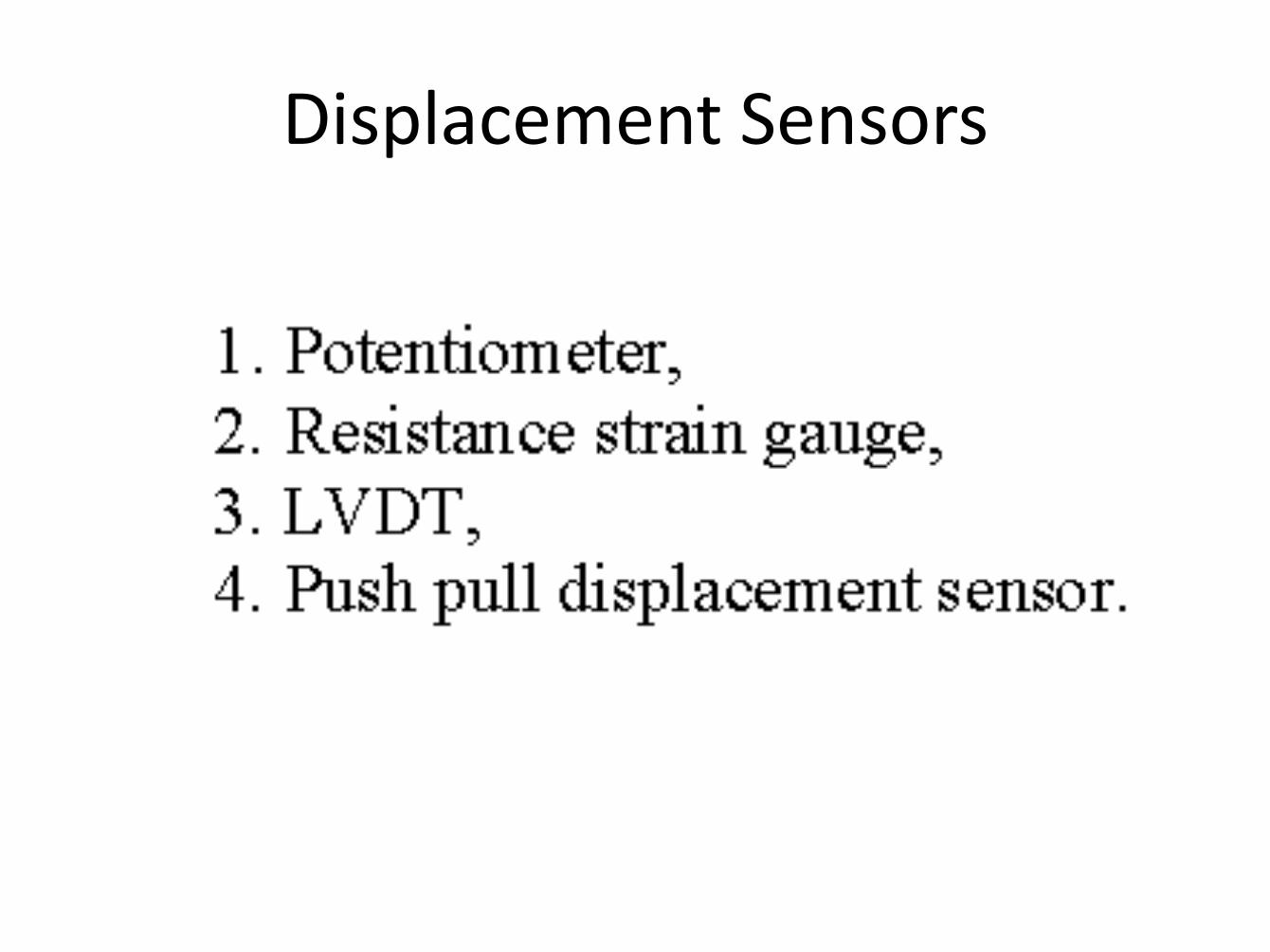
Displacement Sensors
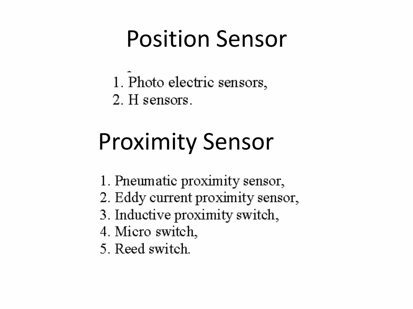
Position Sensor
Proximity Sensor
LINEAR & ANGULAR
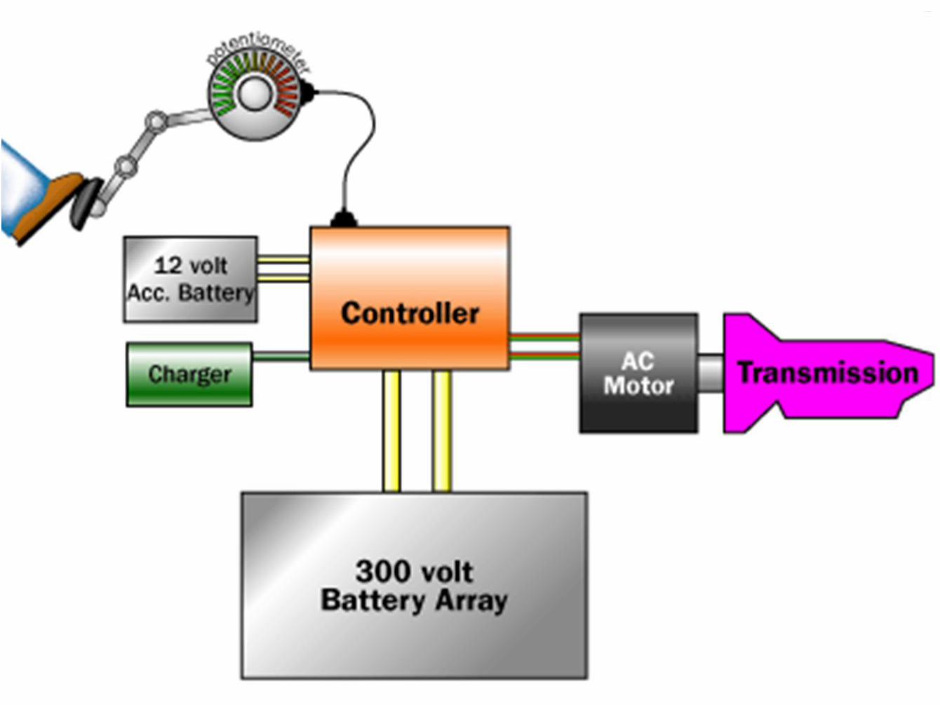
Potentiometer is a variable resistor. Its used to measure the amount of
pressure we apply to the Accelerator. It sends the Electrical Reading to the
Engine Computer to determine how much fuel to push into the Combustion
Chamber (Pistons).
Potentiometer Displacement Sensors
• Electro/mechanical device, used to measure the distance your pedal moves, by using resistance related readings, then send the info to cars ecu which then reacts accordingly
Potentiometer
Resistive Sensors - Potentiometers
Translational and Rotational
Potentiometers
Translational or angular displacement
is proportional to resistance.
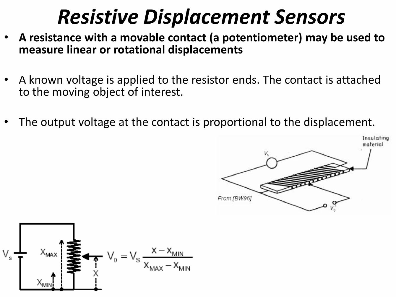
Resistive Displacement Sensors • A resistance with a movable contact (a potentiometer) may be used to
measure linear or rotational displacements
• A known voltage is applied to the resistor ends. The contact is attached to the moving object of interest.
• The output voltage at the contact is proportional to the displacement.
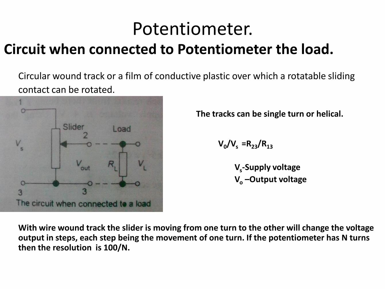
Circuit when connected to Potentiometer the load.
Circular wound track or a film of conductive plastic over which a rotatable sliding
contact can be rotated.
The tracks can be single turn or helical.
Vs-Supply voltage
Vo –Output voltage
With wire wound track the slider is moving from one turn to the other will change the voltage output in steps, each step being the movement of one turn. If the potentiometer has N turns then the resolution is 100/N.
V0/Vs =R23/R13
Potentiometer.
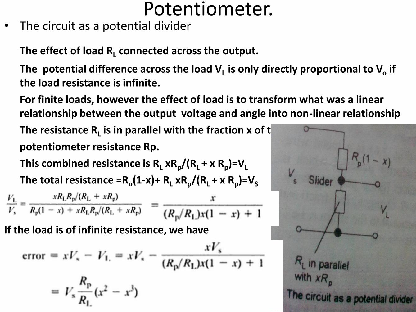
Potentiometer. • The circuit as a potential divider
The effect of load RL connected across the output.
The potential difference across the load VL is only directly proportional to Vo if the load resistance is infinite.
For finite loads, however the effect of load is to transform what was a linear relationship between the output voltage and angle into non-linear relationship
The resistance RL is in parallel with the fraction x of the
potentiometer resistance Rp.
This combined resistance is RL xRp/(RL + x Rp)=VL
The total resistance =Rp(1-x)+ RL xRp/(RL + x Rp)=VS
If the load is of infinite resistance, we have
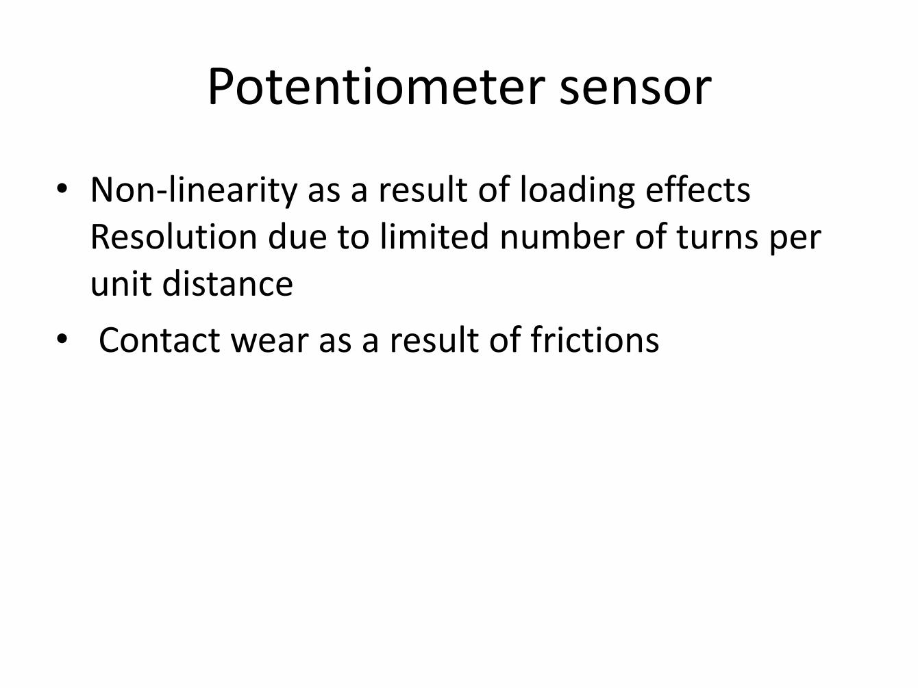
Potentiometer sensor
• Non-linearity as a result of loading effects Resolution due to limited number of turns per unit distance
• Contact wear as a result of frictions
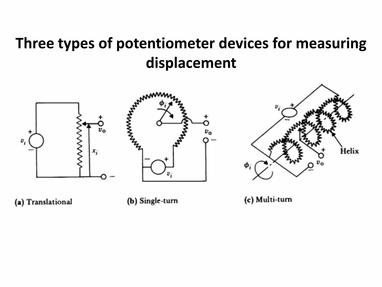
Three types of potentiometer devices for measuring displacement
Choosing a potentiometer
• The important parameters are:
– Temperature
– Shock and vibration
– Humidity
– Altitude
– Others: • Life cycle
• Dither

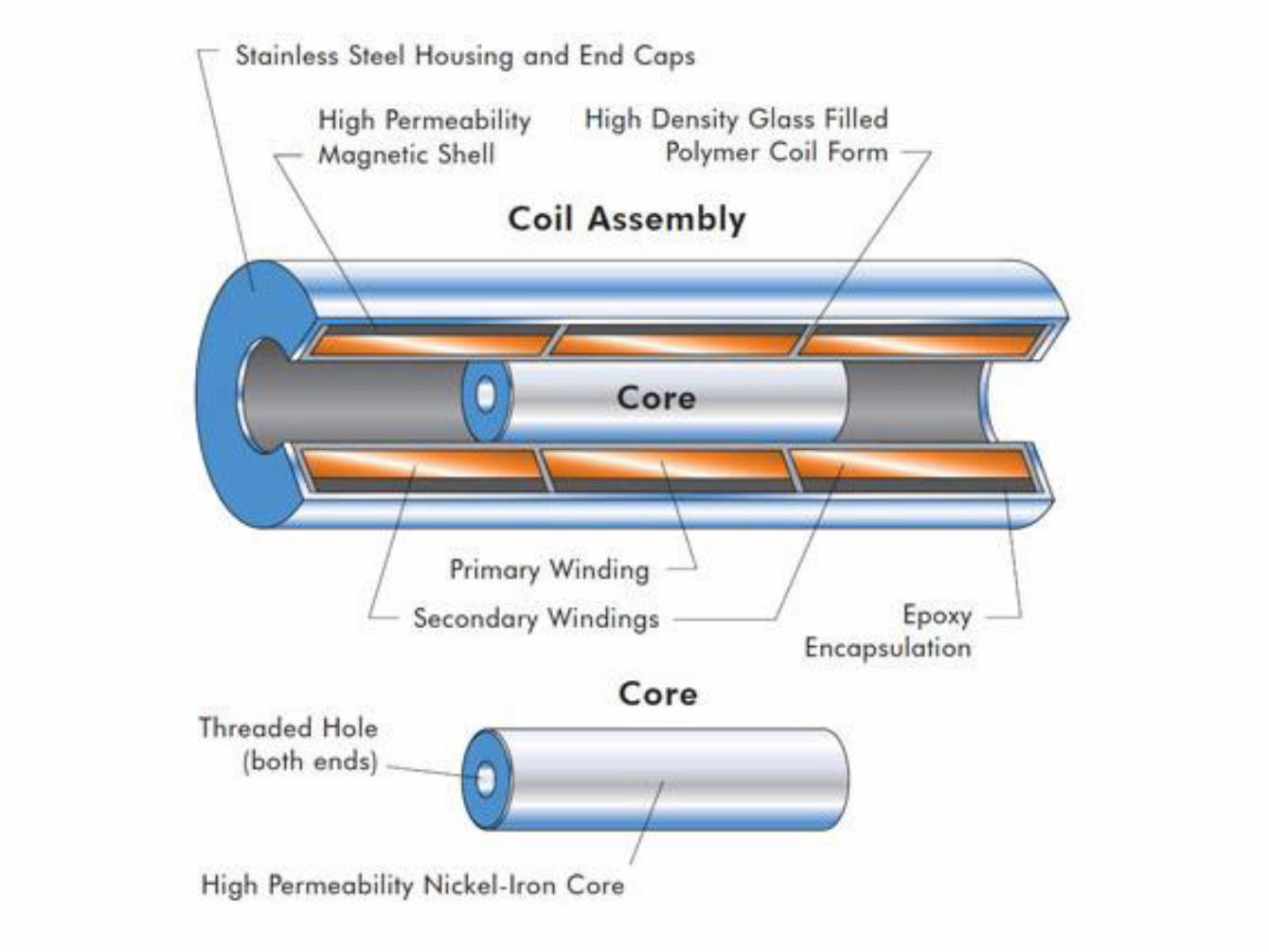
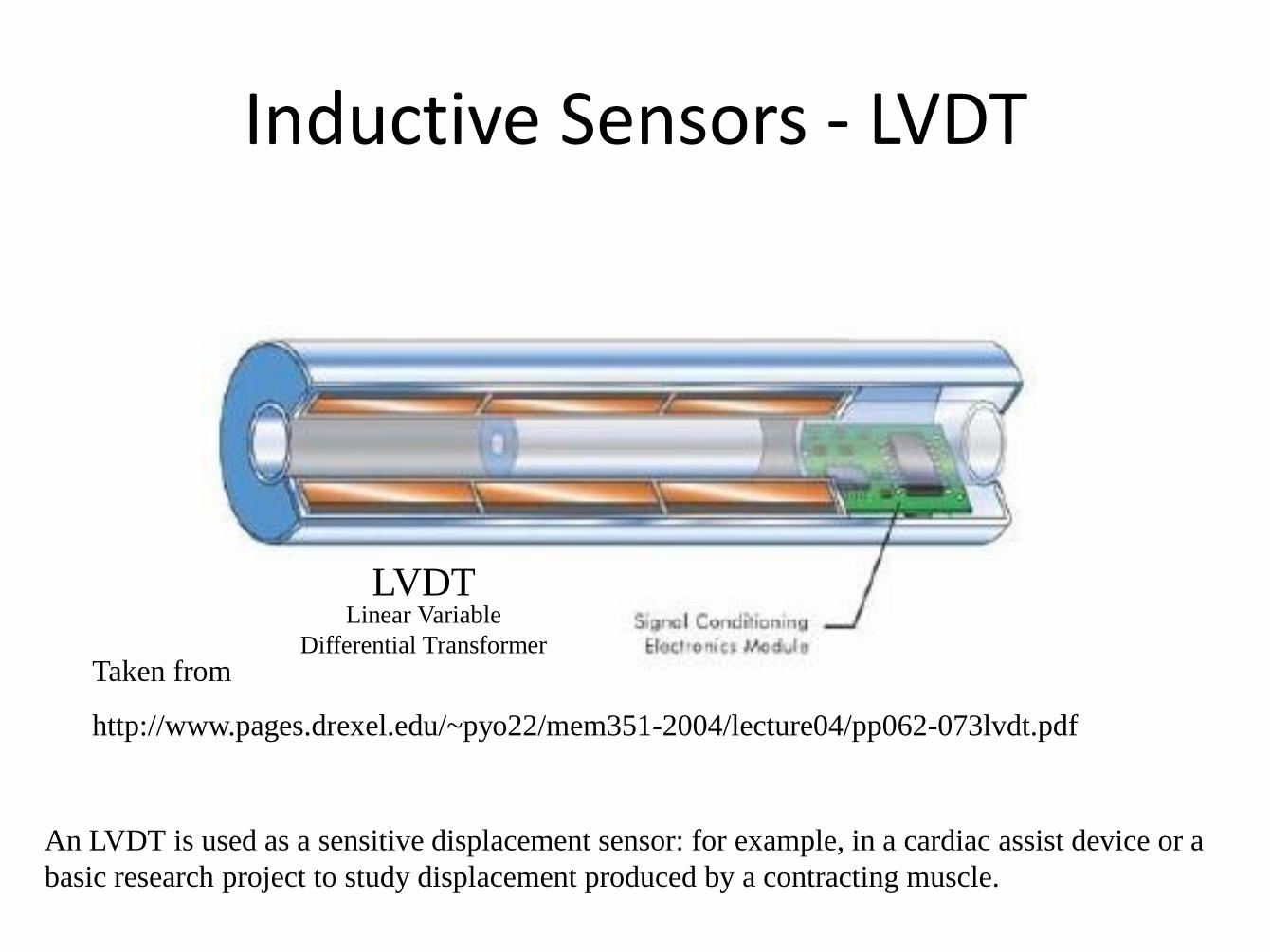
LVDT

Experimental Setup
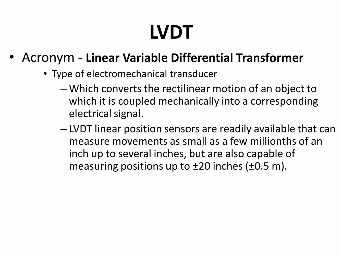
LVDT • Acronym - Linear Variable Differential Transformer
• Type of electromechanical transducer
– Which converts the rectilinear motion of an object to which it is coupled mechanically into a corresponding electrical signal.
– LVDT linear position sensors are readily available that can measure movements as small as a few millionths of an inch up to several inches, but are also capable of measuring positions up to ±20 inches (±0.5 m).
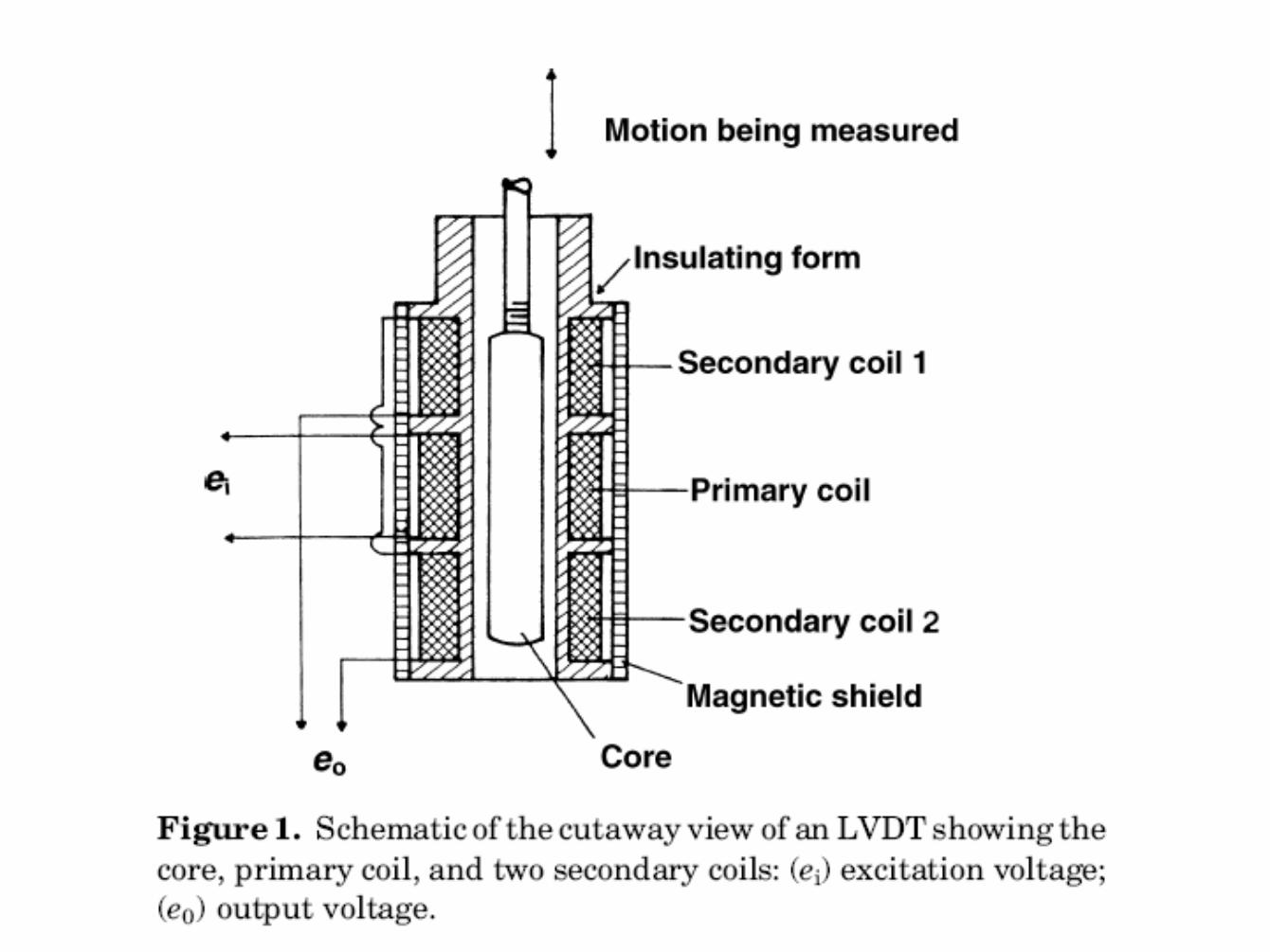
• The transformer's internal structure consists of a primary winding centered between a pair of identically wound secondary windings, symmetrically spaced about the primary.
• The coils are wound on a one-piece hollow form of thermally stable glass reinforced polymer, – encapsulated against moisture,
– wrapped in a high permeability magnetic shield, and
– then secured in a cylindrical stainless steel housing.
– This coil assembly is usually the stationary element of the position sensor.
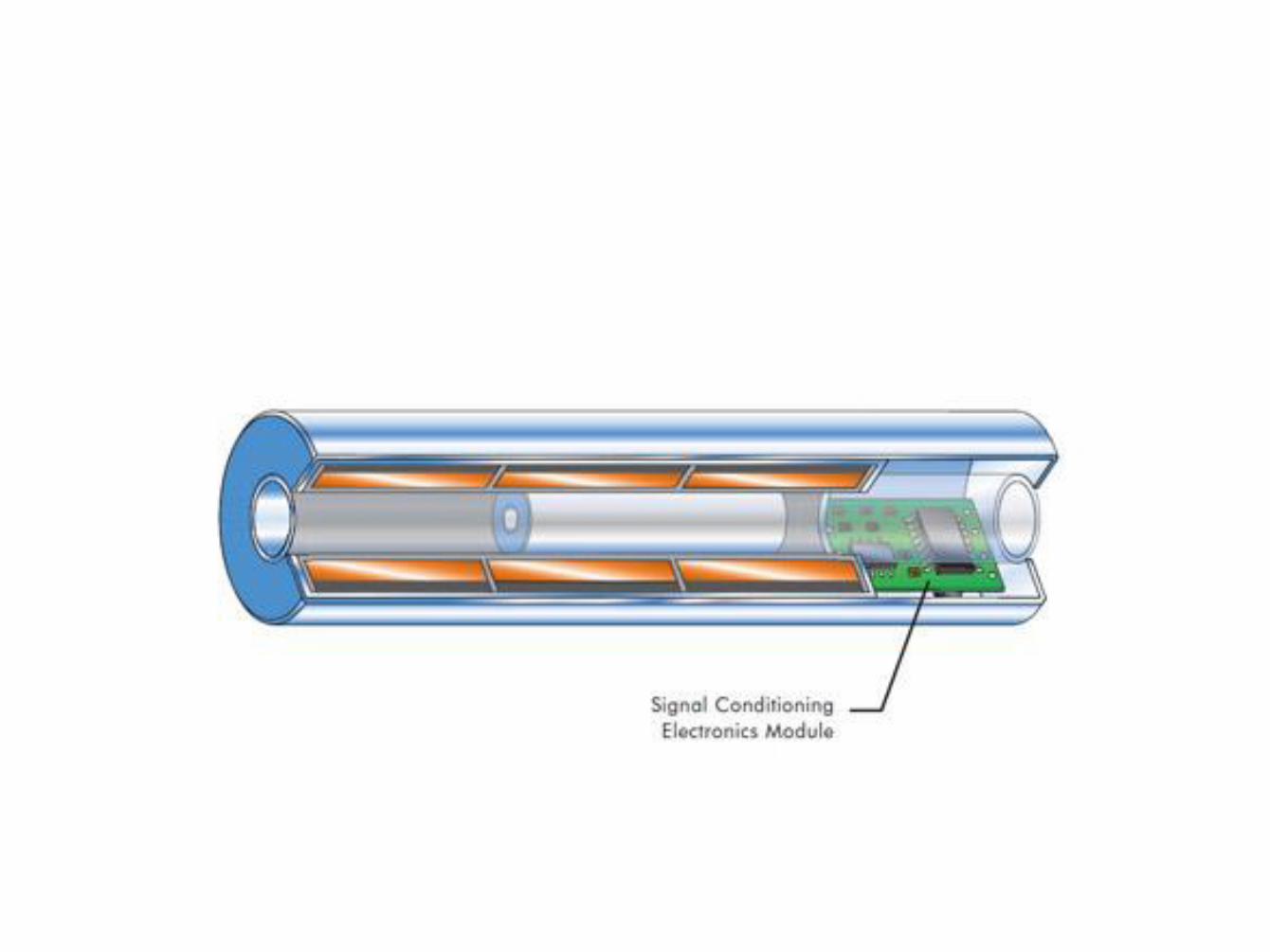
• The moving element of an LVDT is a separate tubular armature of magnetically permeable material called
• core,
• which is free to move axially within the coil's hollow bore, and
• mechanically coupled to the object whose position is being measured.
• This bore is typically large enough to provide substantial radial clearance between the core and bore, with no physical contact between it and the coil.
• In operation, – the LVDT's primary winding is energized by alternating
current of appropriate amplitude and frequency, known as the primary excitation.
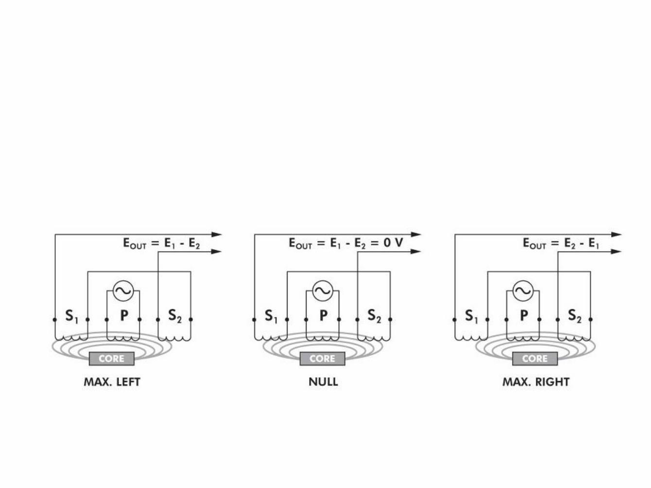
• The LVDT's electrical output signal is the differential AC voltage between the two secondary windings, which varies with the axial position of the core within the LVDT coil.
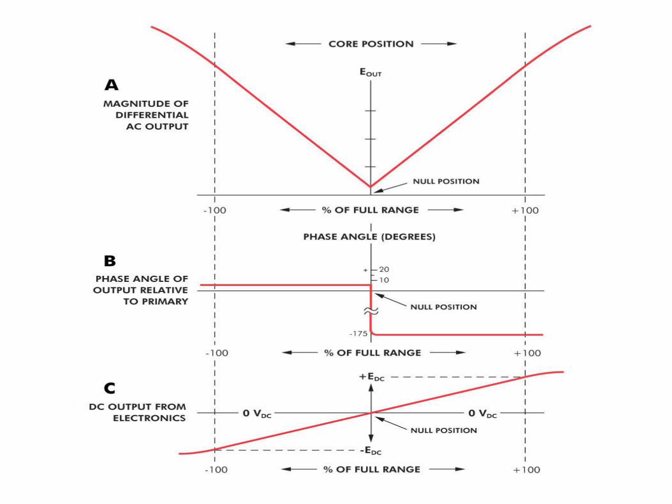
• Usually this AC output voltage is converted by suitable electronic circuitry to high level DC voltage or current that is more convenient to use.
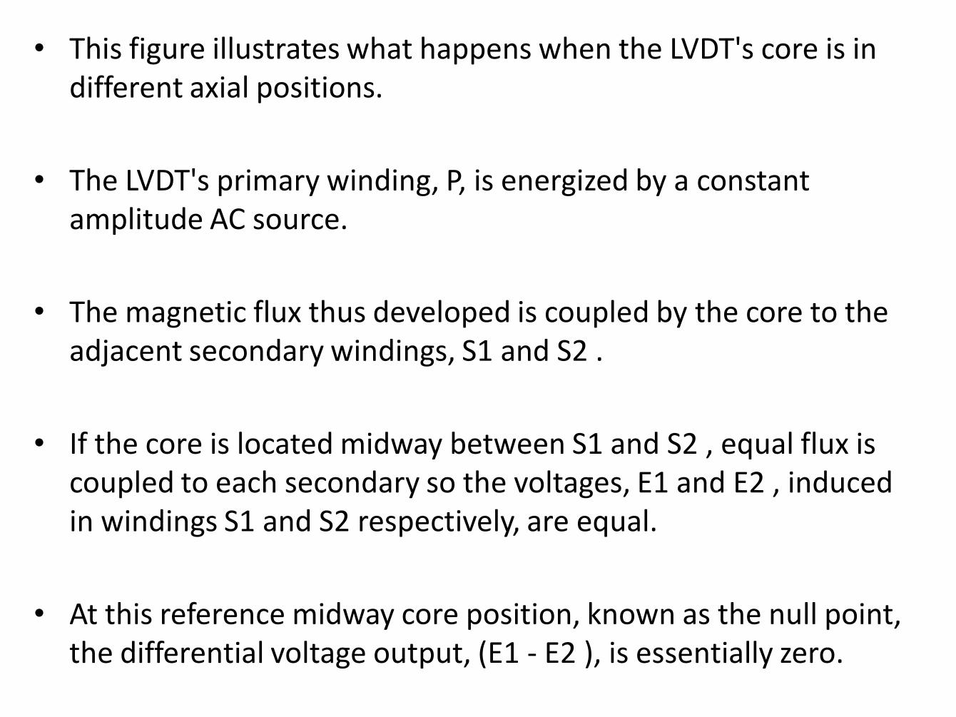
• This figure illustrates what happens when the LVDT's core is in different axial positions.
• The LVDT's primary winding, P, is energized by a constant amplitude AC source.
• The magnetic flux thus developed is coupled by the core to the adjacent secondary windings, S1 and S2 .
• If the core is located midway between S1 and S2 , equal flux is coupled to each secondary so the voltages, E1 and E2 , induced in windings S1 and S2 respectively, are equal.
• At this reference midway core position, known as the null point, the differential voltage output, (E1 - E2 ), is essentially zero.
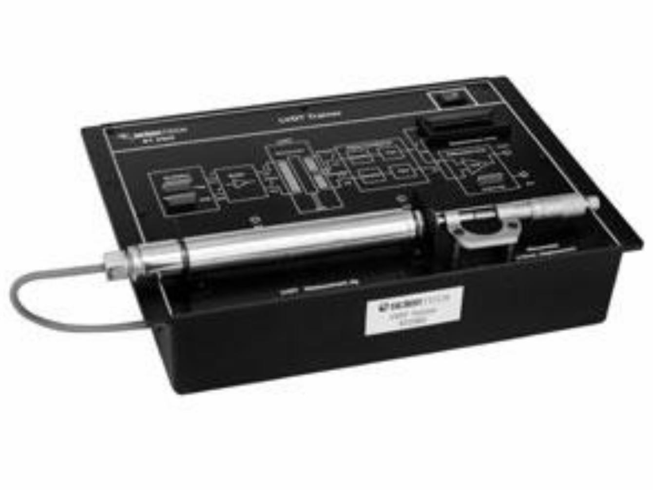
Experimental Setup
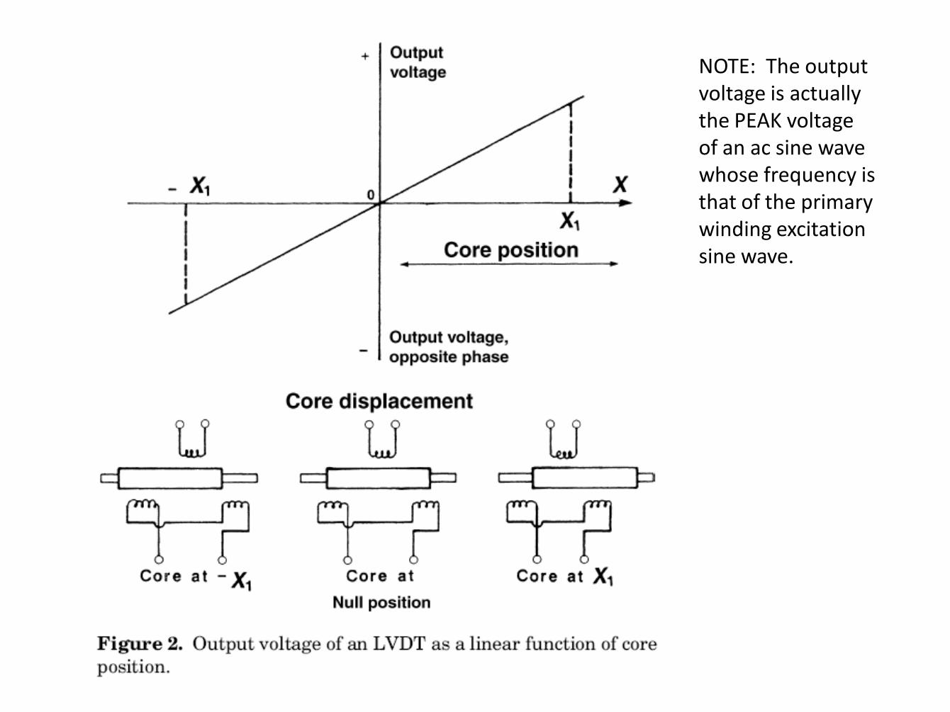
NOTE: The output voltage is actually the PEAK voltage of an ac sine wave whose frequency is that of the primary winding excitation sine wave.
LVDT showing AC Excitation and Phase Sensitive Demodulator
• If the core is moved closer to S1 than to S2 , more flux is coupled to S1 and less to S2 ,
– so the induced voltage E1 is increased while E2 is decreased,
– resulting in the differential voltage (E1 - E2).
• Conversely, if the core is moved closer to S2 , more flux is coupled to S2 and less to S1 ,
– so E2 is increased as E1 is decreased,
– resulting in the differential voltage (E2 - E1 ).
• The top graph shows how the magnitude of the differential output voltage, EOUT, varies with core position.
• The value of EOUT at maximum core displacement from null depends upon the amplitude of the primary excitation voltage and the sensitivity factor of the particular LVDT, but is typically several volts RMS.
• The phase angle of this AC output voltage, EOUT, referenced to the primary excitation voltage, stays constant until the center of the core passes the null point, where the phase angle changes abruptly by 180 degrees, as shown in the middle graph.
Application • LVDT is used in various fields like Automation Machinery, Civil /
Structural Engineering, Power Generation, Manufacturing, Metal Stamping / Forming, OEM, Pulp and Paper, Industrial Valves, R&D and Test, Automotive Racing etc..
• Measuring displacement of diamond tip to determine material hardness.
• Measurement of die wear, high speed injection molding equipment. • Position feed back for automated spot welding control system. • Special unit used in linear actuator position feed back aircraft
ailerons. • Measuring final height placement for automotive wheel trim • Measuring injector height for diesel engines • Measure movement of specific features of foam core used in lost
foam casting process during sand compaction operation. • Height measurement of screws after insertion into automotive door
assembly. • Thickness measuring in multiple locations of flywheel to insure
balance. • Expansion measurement of solid fuel rocket motor casing during
temperature testing.
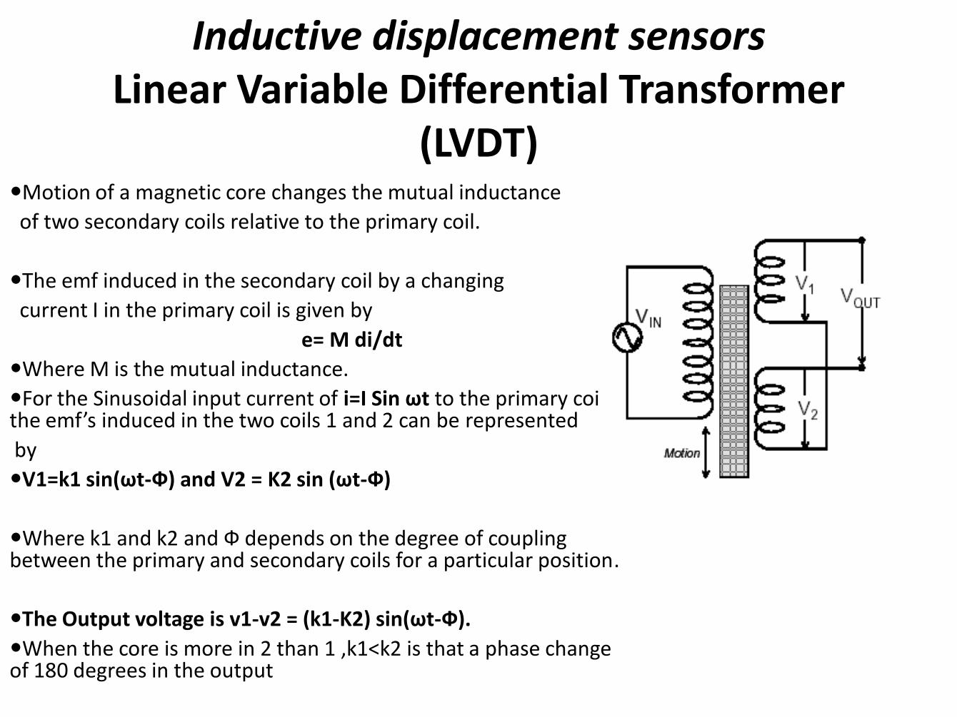
Inductive displacement sensors Linear Variable Differential Transformer
(LVDT) Motion of a magnetic core changes the mutual inductance
of two secondary coils relative to the primary coil.
The emf induced in the secondary coil by a changing
current I in the primary coil is given by
e= M di/dt
Where M is the mutual inductance.
For the Sinusoidal input current of i=I Sin ωt to the primary coil the emf’s induced in the two coils 1 and 2 can be represented
by
V1=k1 sin(ωt-Ф) and V2 = K2 sin (ωt-Ф)
Where k1 and k2 and Ф depends on the degree of coupling between the primary and secondary coils for a particular position.
The Output voltage is v1-v2 = (k1-K2) sin(ωt-Ф).
When the core is more in 2 than 1 ,k1<k2 is that a phase change of 180 degrees in the output
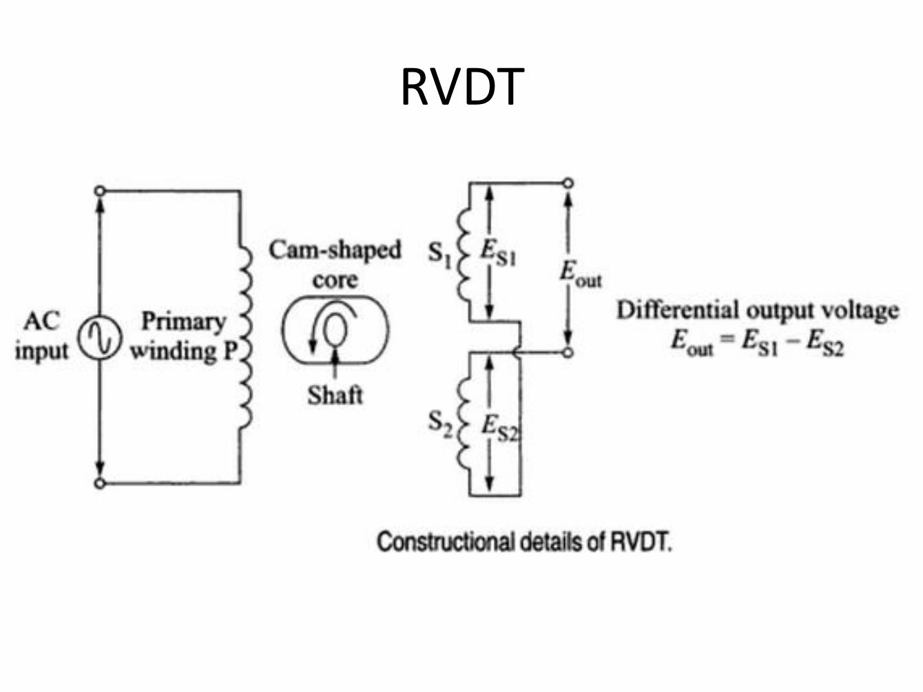
RVDT
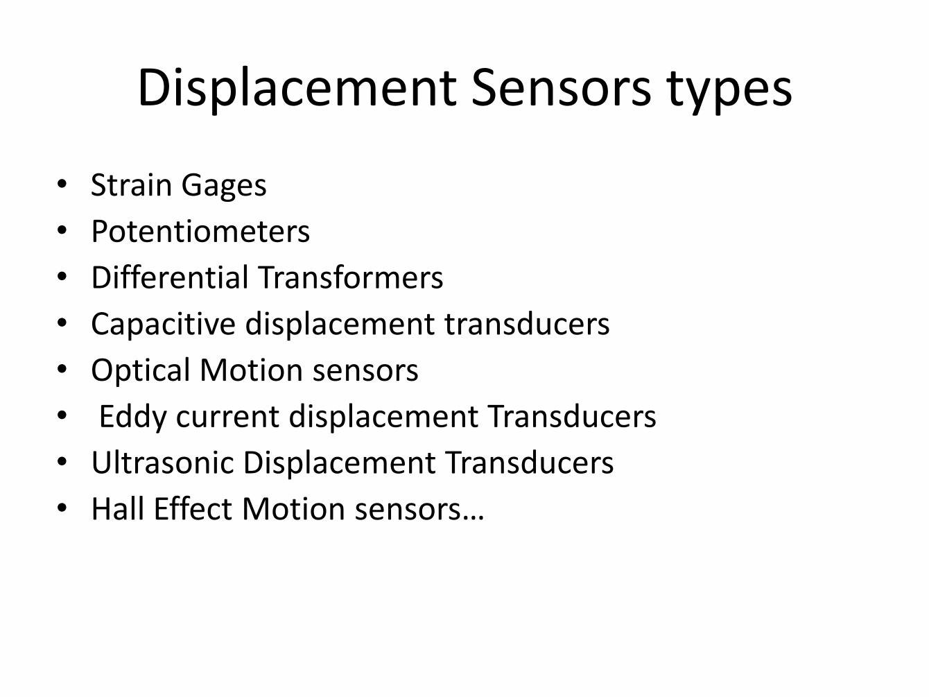
Displacement Sensors types
• Strain Gages
• Potentiometers
• Differential Transformers
• Capacitive displacement transducers
• Optical Motion sensors
• Eddy current displacement Transducers
• Ultrasonic Displacement Transducers
• Hall Effect Motion sensors…
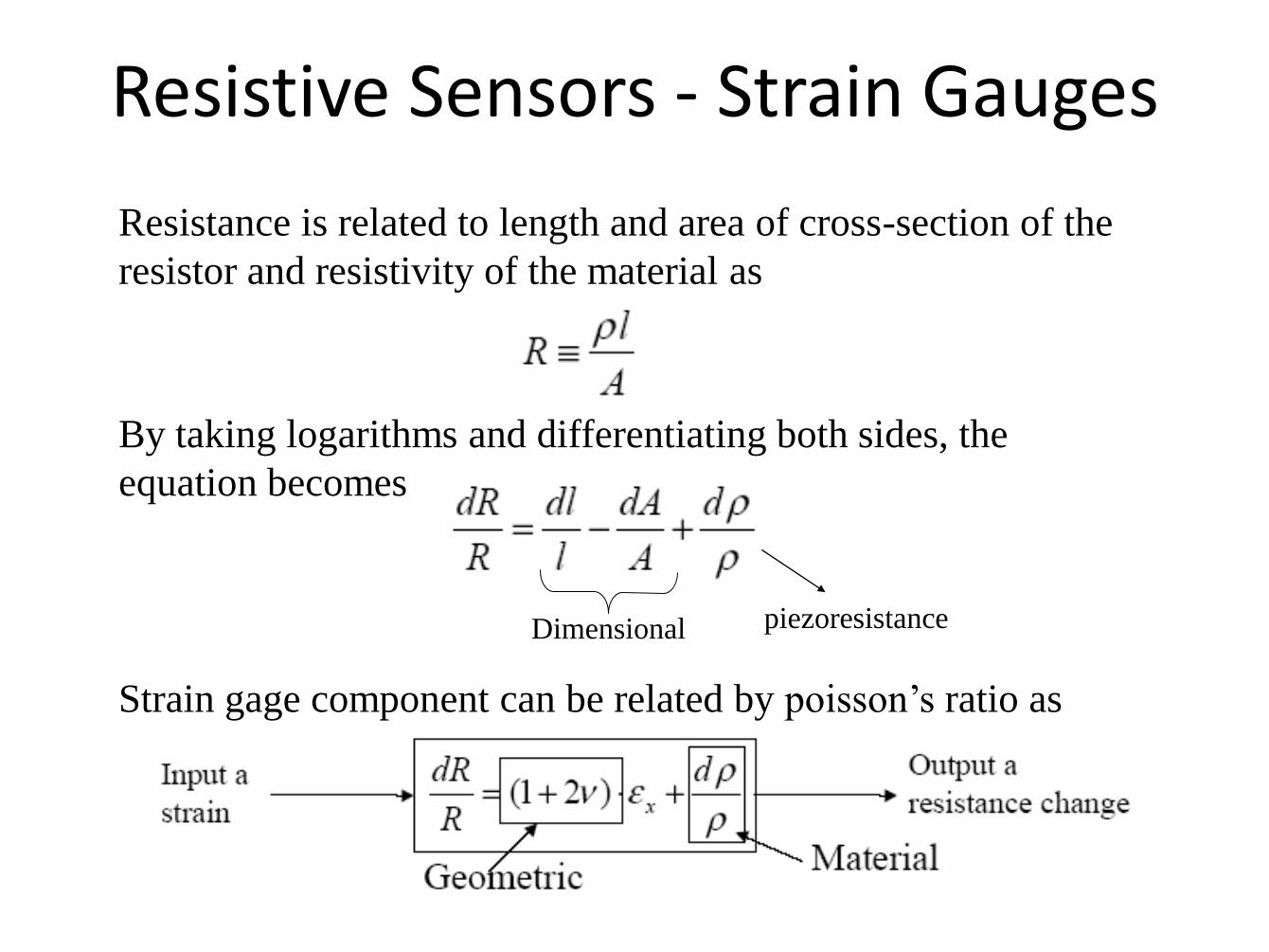
Resistive Sensors - Strain Gauges
Resistance is related to length and area of cross-section of the
resistor and resistivity of the material as
By taking logarithms and differentiating both sides, the
equation becomes
Dimensional piezoresistance
Strain gage component can be related by poisson’s ratio as
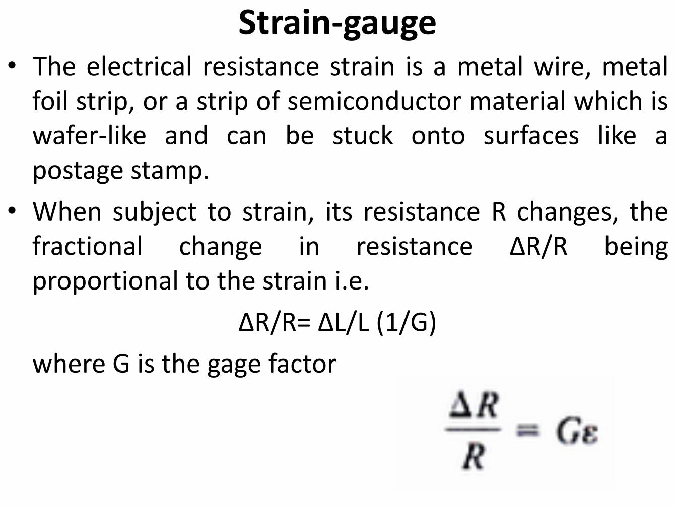
Strain-gauge • The electrical resistance strain is a metal wire, metal
foil strip, or a strip of semiconductor material which is wafer-like and can be stuck onto surfaces like a postage stamp.
• When subject to strain, its resistance R changes, the fractional change in resistance ΔR/R being proportional to the strain i.e.
ΔR/R= ΔL/L (1/G)
where G is the gage factor
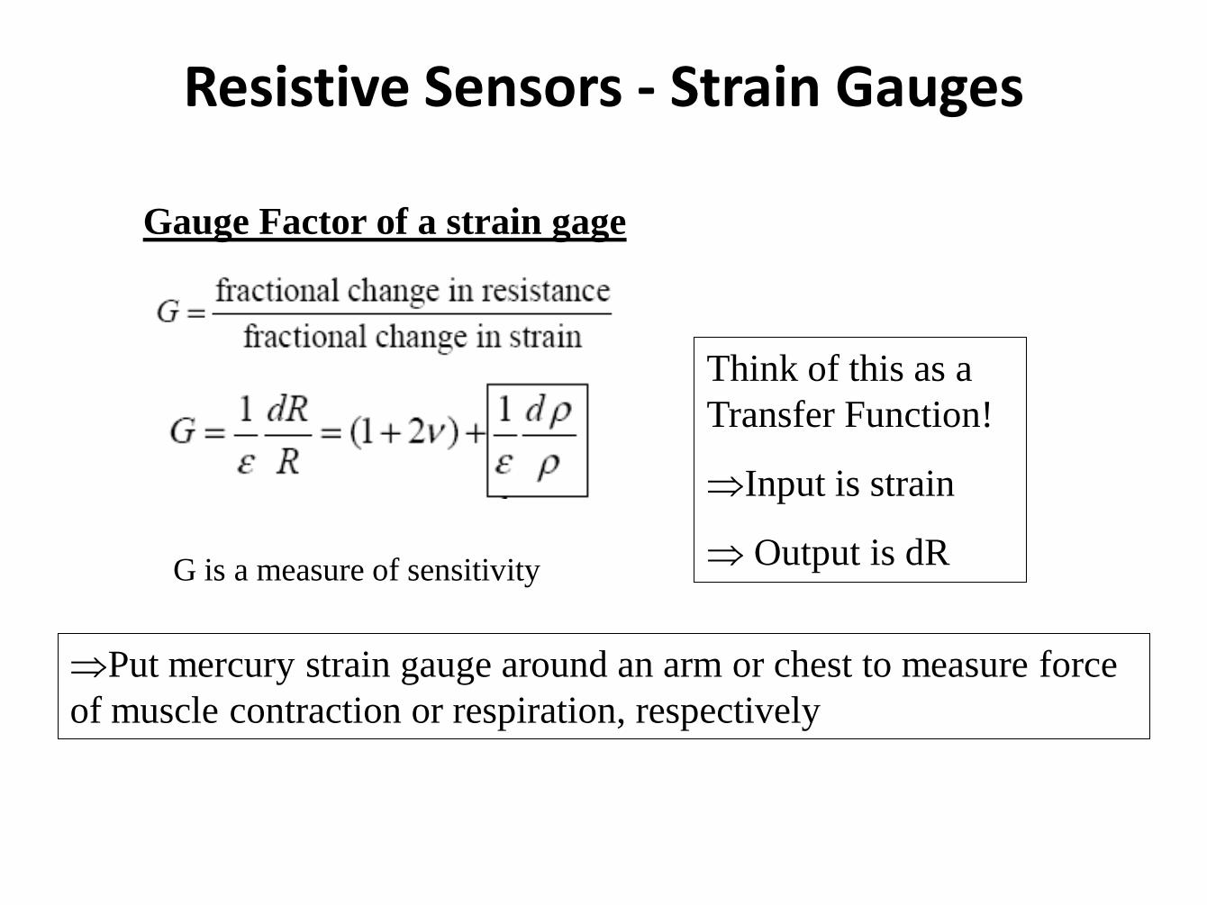
Resistive Sensors - Strain Gauges
Gauge Factor of a strain gage
G is a measure of sensitivity
Think of this as a
Transfer Function!
Input is strain
Output is dR
Put mercury strain gauge around an arm or chest to measure force
of muscle contraction or respiration, respectively
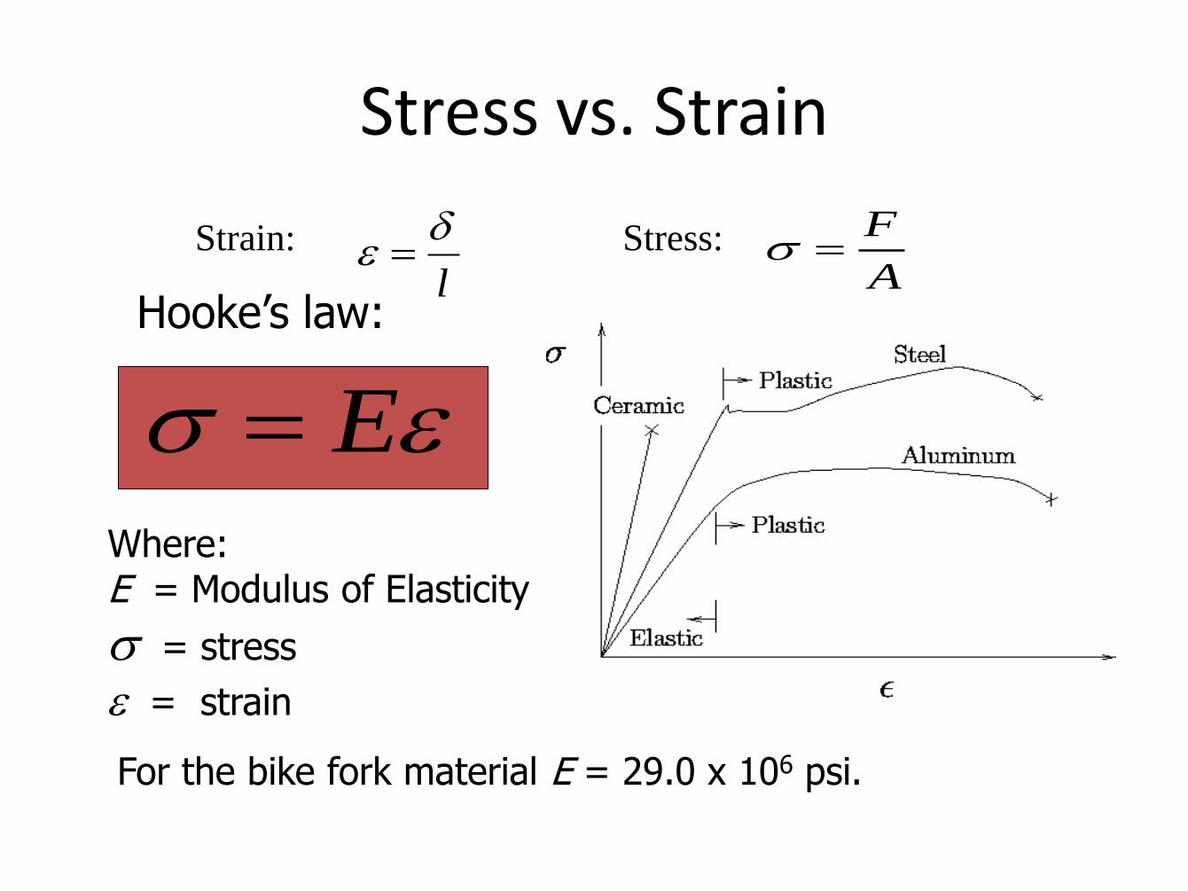
Stress vs. Strain
EWhere: E = Modulus of Elasticity
= stress
= strain
For the bike fork material E = 29.0 x 10⁶ psi.
Strain: Stress:
l
A
F
Hooke’s law:
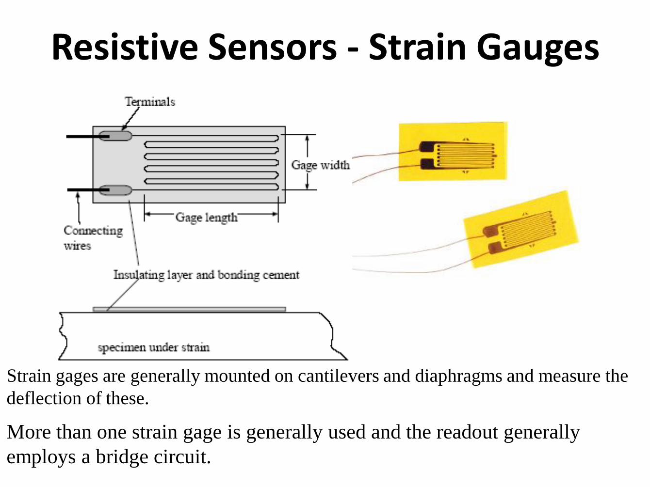
Resistive Sensors - Strain Gauges
Strain gages are generally mounted on cantilevers and diaphragms and measure the
deflection of these.
More than one strain gage is generally used and the readout generally
employs a bridge circuit.
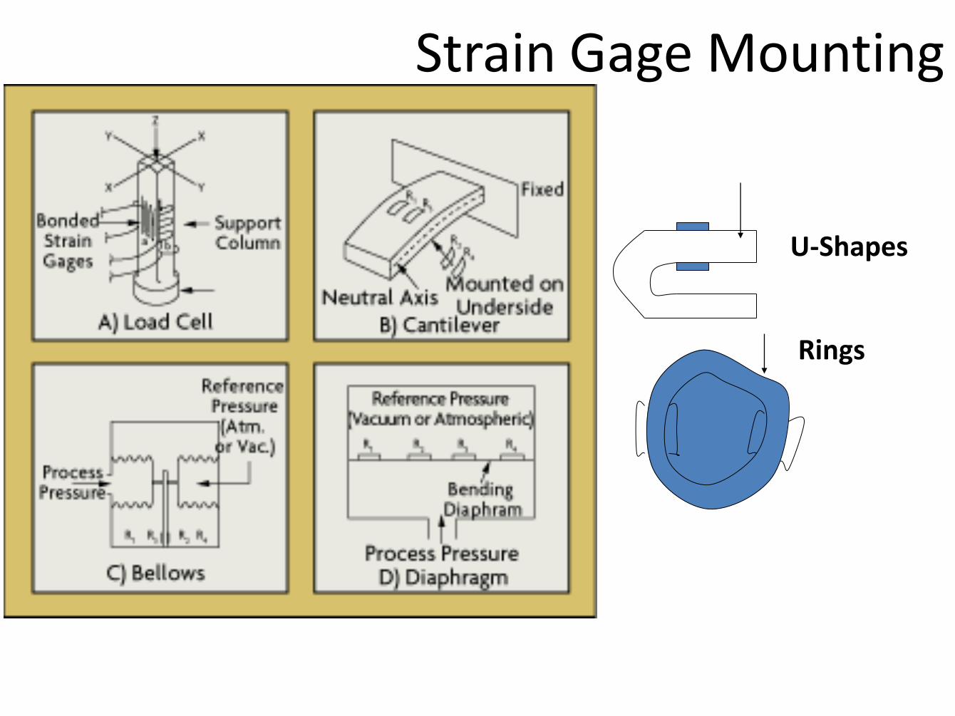
Strain Gage Mounting
U-Shapes
Rings
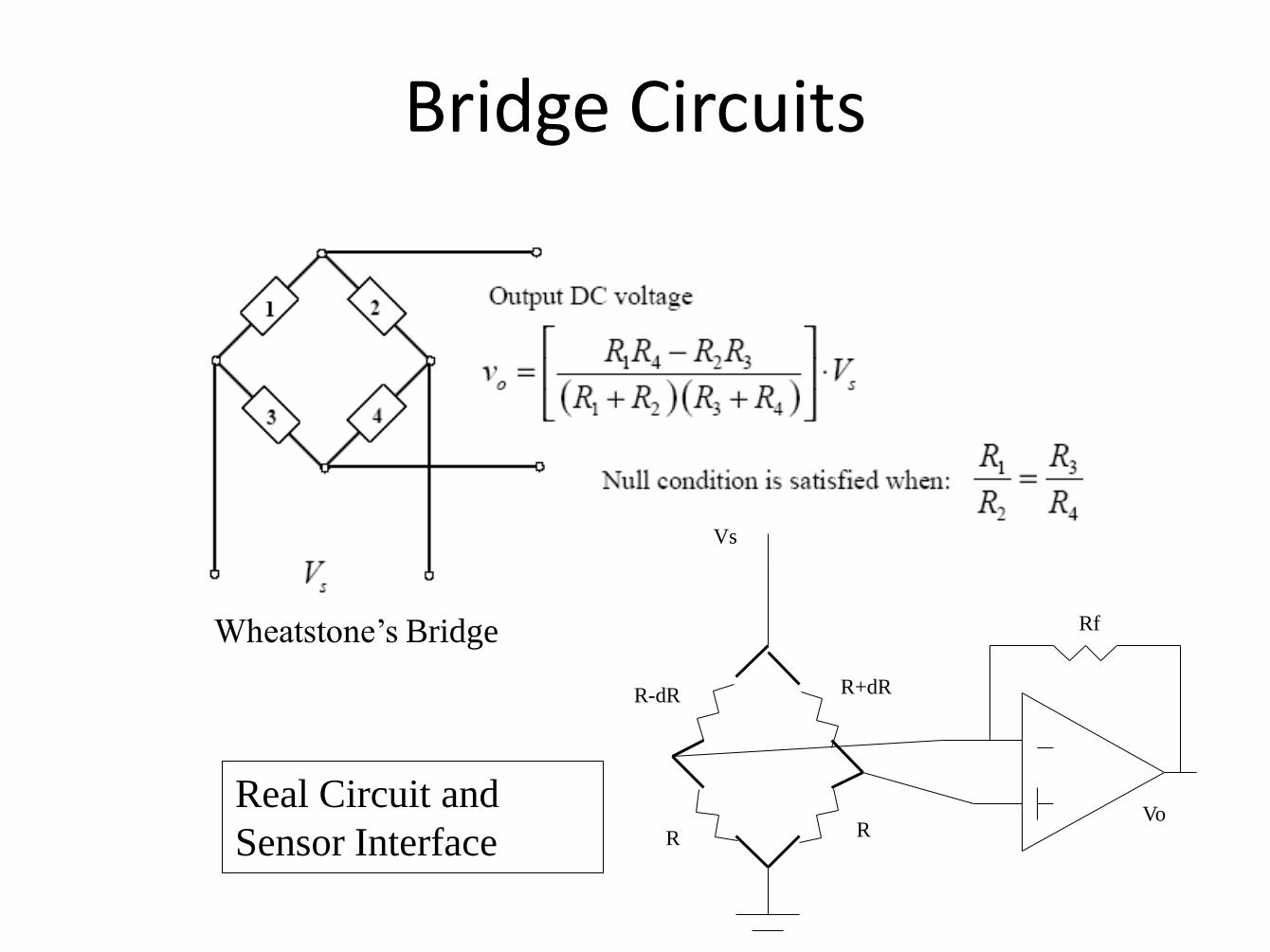
Bridge Circuits
Wheatstone’s Bridge
R-dR R+dR
R
Rf
Vs
R Vo
Real Circuit and
Sensor Interface
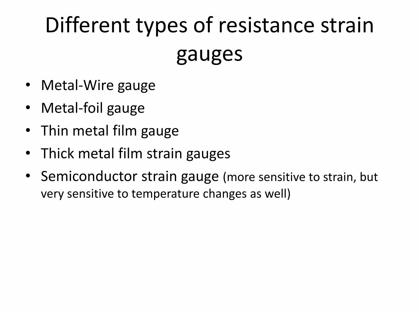
Different types of resistance strain gauges
• Metal-Wire gauge
• Metal-foil gauge
• Thin metal film gauge
• Thick metal film strain gauges
• Semiconductor strain gauge (more sensitive to strain, but
very sensitive to temperature changes as well)
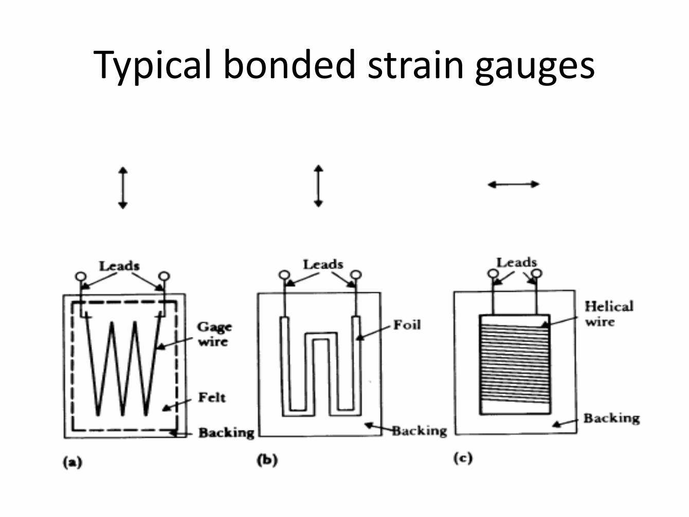
Typical bonded strain gauges
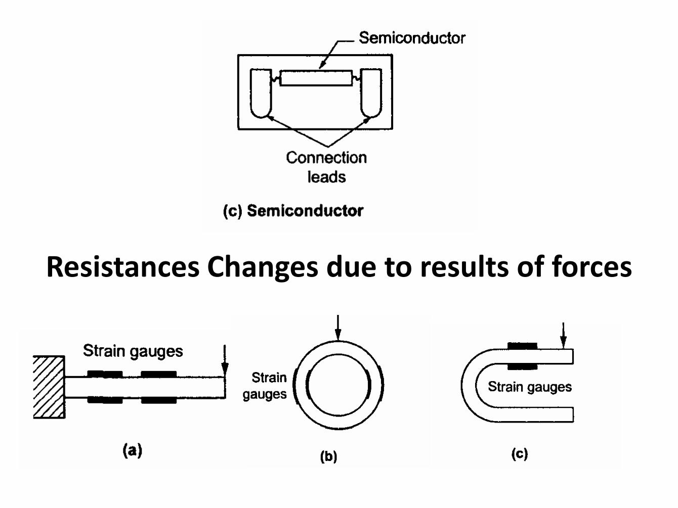
Resistances Changes due to results of forces
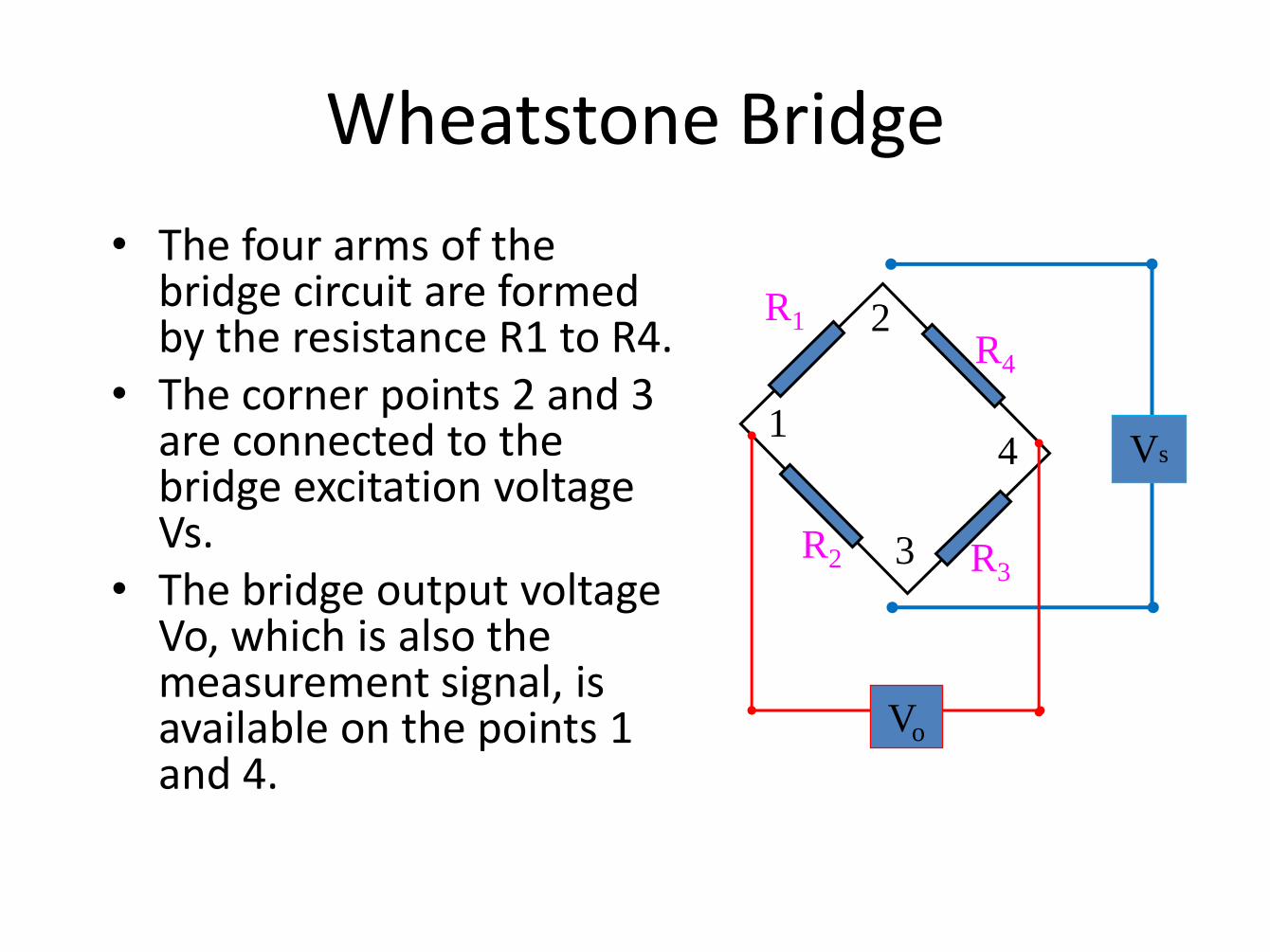
Wheatstone Bridge
• The four arms of the bridge circuit are formed by the resistance R1 to R4.
• The corner points 2 and 3 are connected to the bridge excitation voltage Vs.
• The bridge output voltage Vo, which is also the measurement signal, is available on the points 1 and 4.
1
2
4
3
R4 R1
R2 R3
Vs
Vo

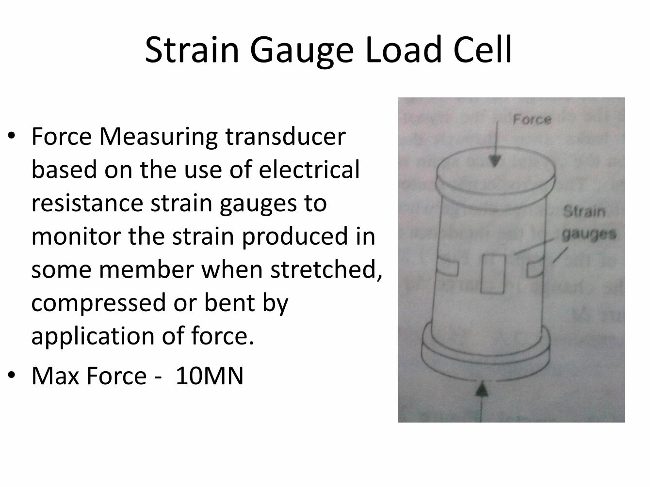
Strain Gauge Load Cell
• Force Measuring transducer based on the use of electrical resistance strain gauges to monitor the strain produced in some member when stretched, compressed or bent by application of force.
• Max Force - 10MN
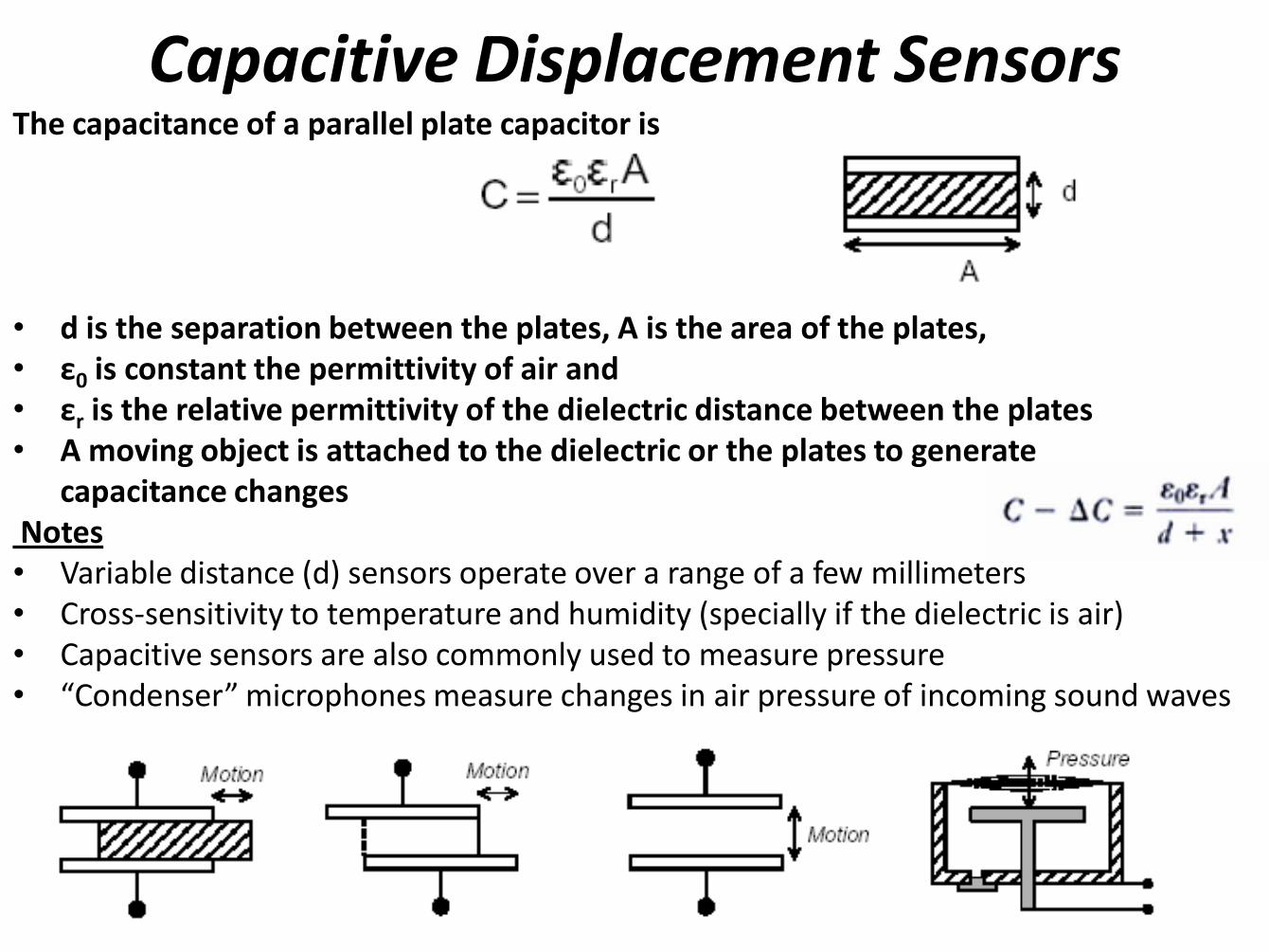
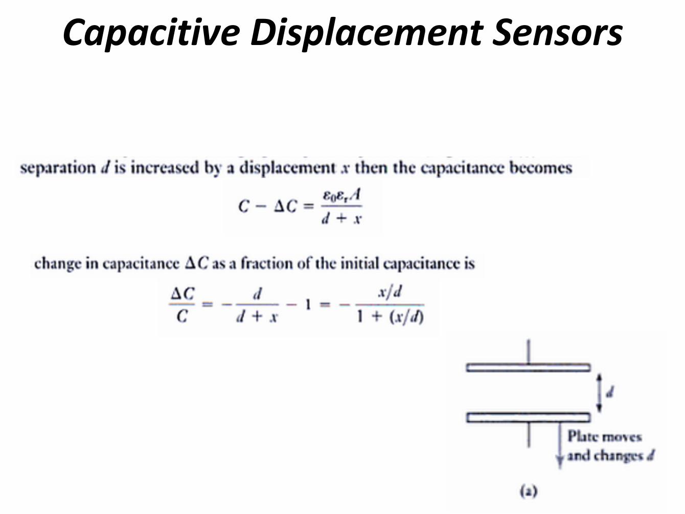
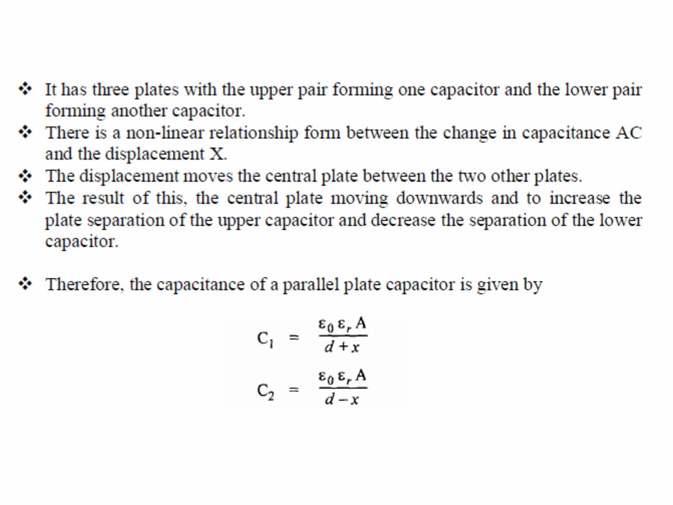
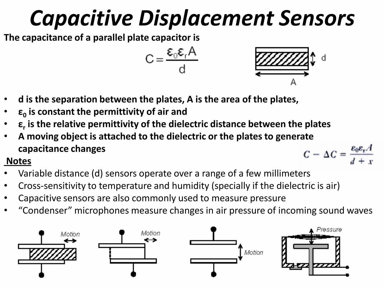
Capacitive Displacement Sensors
The capacitance of a parallel plate capacitor is
• d is the separation between the plates, A is the area of the plates, • ε0 is constant the permittivity of air and • εr is the relative permittivity of the dielectric distance between the plates • A moving object is attached to the dielectric or the plates to generate capacitance changes Notes • Variable distance (d) sensors operate over a range of a few millimeters • Cross-sensitivity to temperature and humidity (specially if the dielectric is air) • Capacitive sensors are also commonly used to measure pressure • “Condenser” microphones measure changes in air pressure of incoming sound waves
Capacitive Displacement Sensors
Capacitive Sensors
e.g. An electrolytic
capacitor is made of
Aluminum
evaporated on either
side of a very thin
plastic film (or
electrolyte)
Electrolytic or
ceramic capacitors
are most common
Capacitive Sensors Other Configurations
c. Differential Mode
b. Variable Dielectric Mode
a. Variable Area Mode
Capacitive displacement sensors
The capacitance of a parallel plate capacitor is
• d is the separation between the plates, A is the area of the plates,
• ε0 is the permittivity of air and
• εr is the relative permittivity of the dielectric
• A moving object is attached to the dielectric or the plates to generate capacitance changes
Notes • Variable distance (d) sensors operate over a range of a few millimeters • Cross-sensitivity to temperature and humidity (specially if the dielectric is air) • Capacitive sensors are also commonly used to measure pressure • “Condenser” microphones measure changes in air pressure of incoming sound waves

Capacitive Sensors Other Configurations
c. Differential Mode
b. Variable Dielectric Mode
a. Variable Area Mode
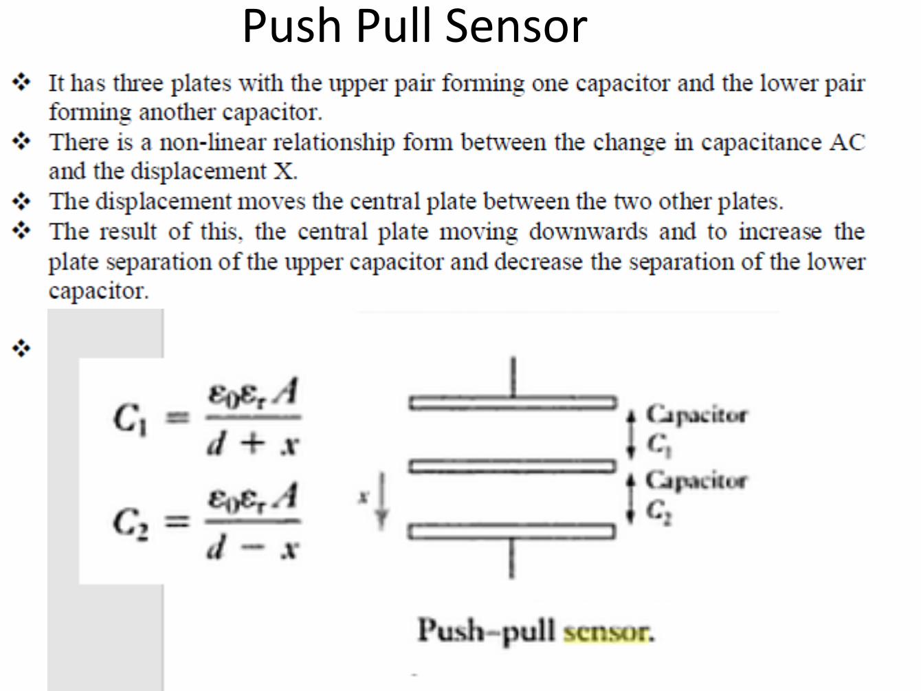
Push Pull Sensor

Capacitive Proximity Sensor

Major Types and Uses of Capacitive Transducers
• Position Sensors
– Capacitive Displacement Sensors
– Capacitive Differential Sensors
– Variable Area Displacement Sensors
• Accelerometers
– Differential-Capacitive Accelometer
• Force
– Capacitive Force Transducer
• Tactile Sensing
• Proximity Sensors
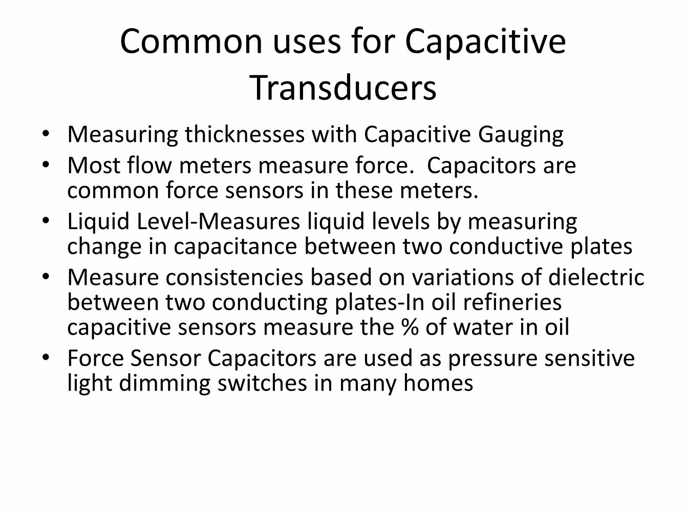
Common uses for Capacitive Transducers
• Measuring thicknesses with Capacitive Gauging • Most flow meters measure force. Capacitors are
common force sensors in these meters. • Liquid Level-Measures liquid levels by measuring
change in capacitance between two conductive plates • Measure consistencies based on variations of dielectric
between two conducting plates-In oil refineries capacitive sensors measure the % of water in oil
• Force Sensor Capacitors are used as pressure sensitive light dimming switches in many homes
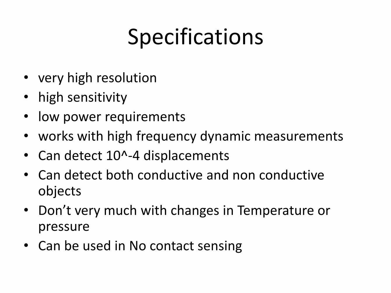
Specifications
• very high resolution
• high sensitivity
• low power requirements
• works with high frequency dynamic measurements
• Can detect 10^-4 displacements
• Can detect both conductive and non conductive objects
• Don’t very much with changes in Temperature or pressure
• Can be used in No contact sensing
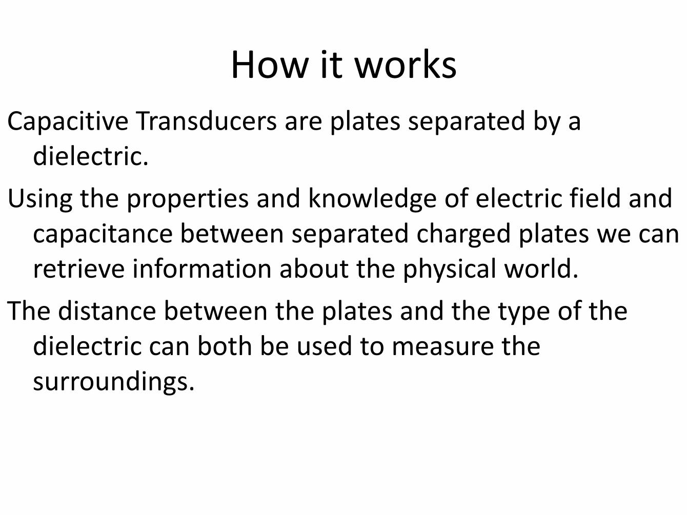
How it works Capacitive Transducers are plates separated by a
dielectric.
Using the properties and knowledge of electric field and capacitance between separated charged plates we can retrieve information about the physical world.
The distance between the plates and the type of the dielectric can both be used to measure the surroundings.
Limitations
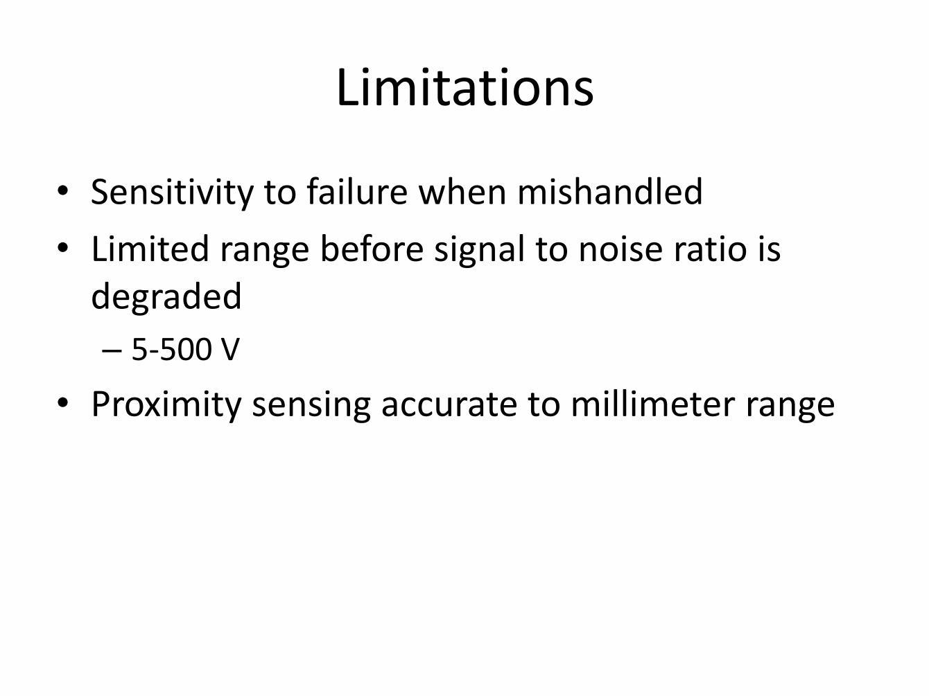
• Sensitivity to failure when mishandled
• Limited range before signal to noise ratio is degraded
– 5-500 V
• Proximity sensing accurate to millimeter range
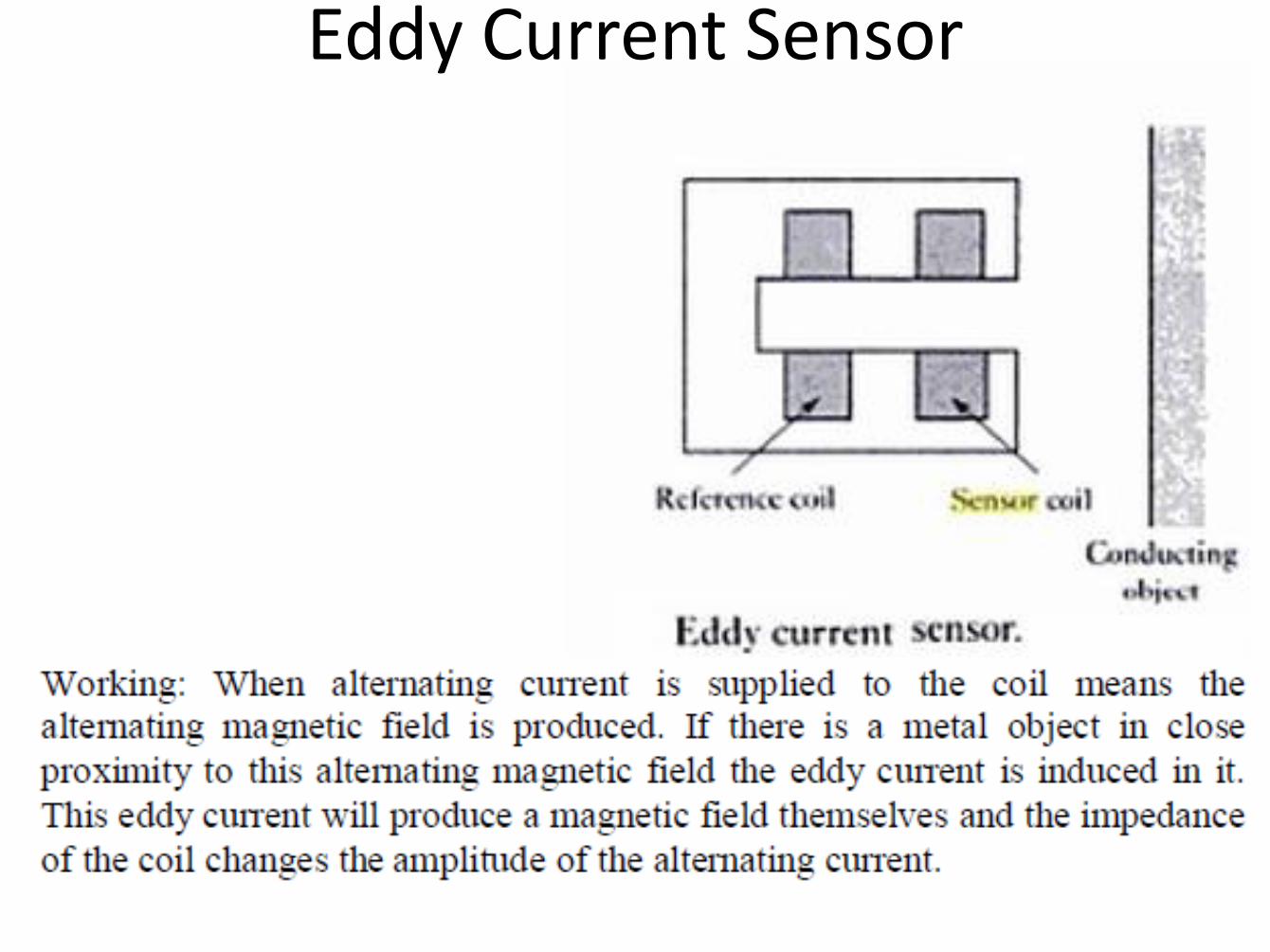
Eddy Current Sensor

Inductive Proximity Sensor
• The inductive proximity sensor can be used to detect metallic targets only.
• The main components of the inductive proximity sensor are coil, oscillator, detector and the output circuit.
• The coil generates the high frequency magnetic field in front of the face.
• When the metallic target comes in this magnetic field it absorbs some of the energy.
• Hence the oscillator field is affected. This is detected by the detector. if the oscillation amplitude reaches a certain threshold value the output switches.
• The inductive proximity sensor works better with ferromagnetic targets as they absorb more energy compare to non Ferromagnetic materials. Hence operating distance for sensor is more for Ferromagnetic targets.
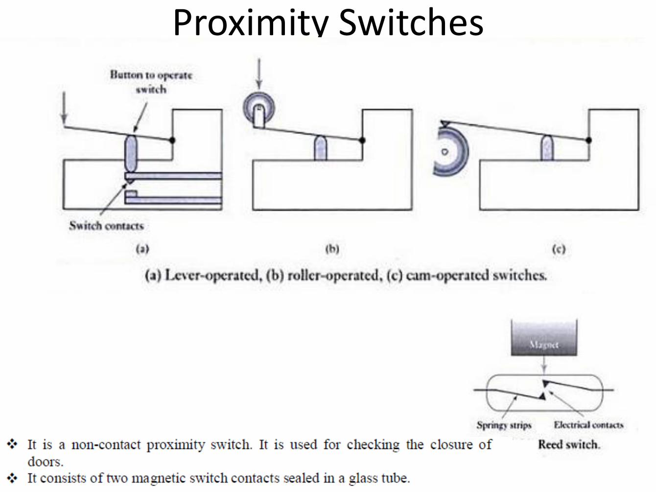
Proximity Switches
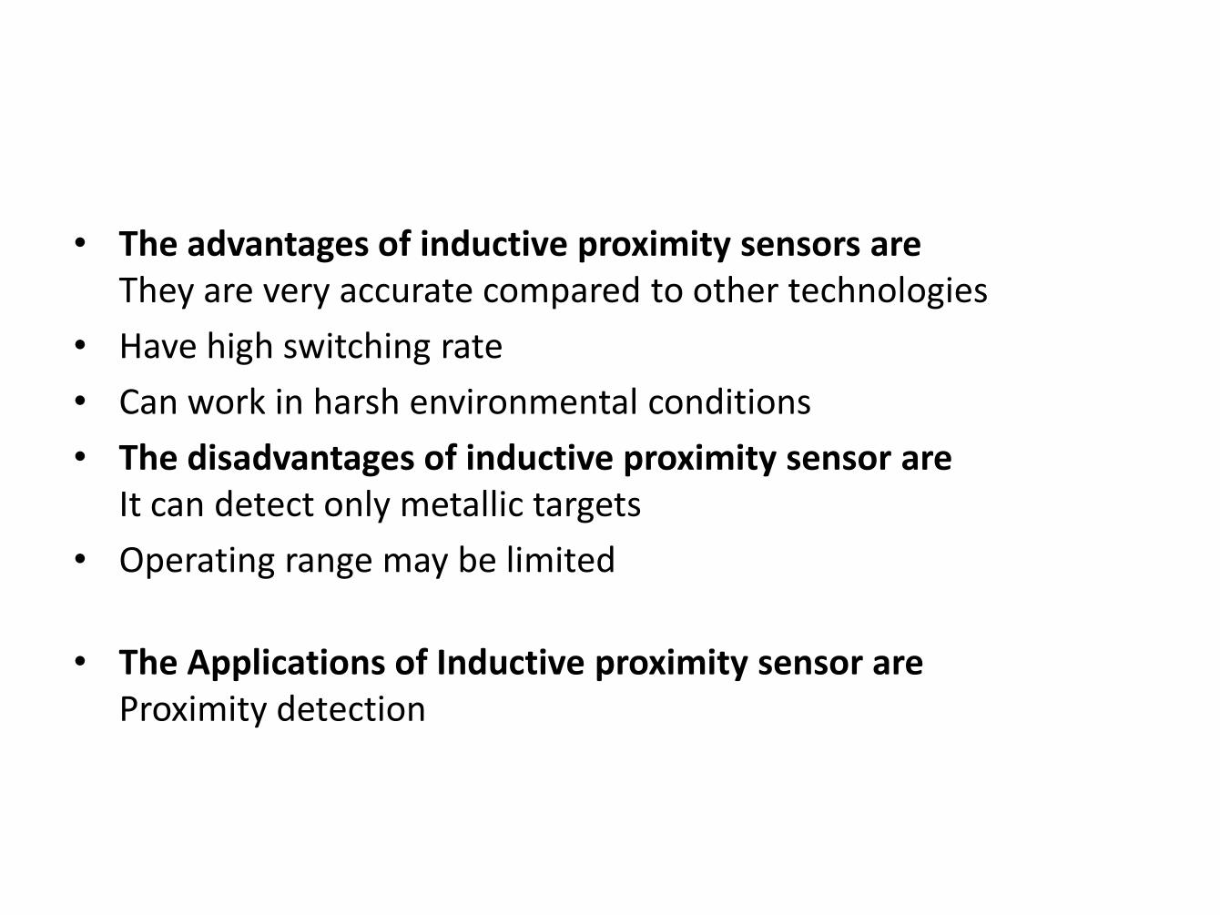
• The advantages of inductive proximity sensors are They are very accurate compared to other technologies
• Have high switching rate
• Can work in harsh environmental conditions
• The disadvantages of inductive proximity sensor are It can detect only metallic targets
• Operating range may be limited
• The Applications of Inductive proximity sensor are Proximity detection
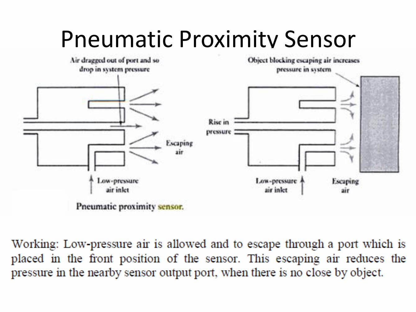
Pneumatic Proximity Sensor
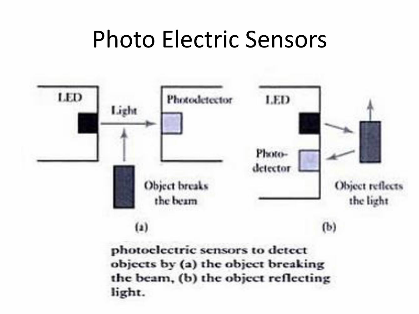
Photo Electric Sensors
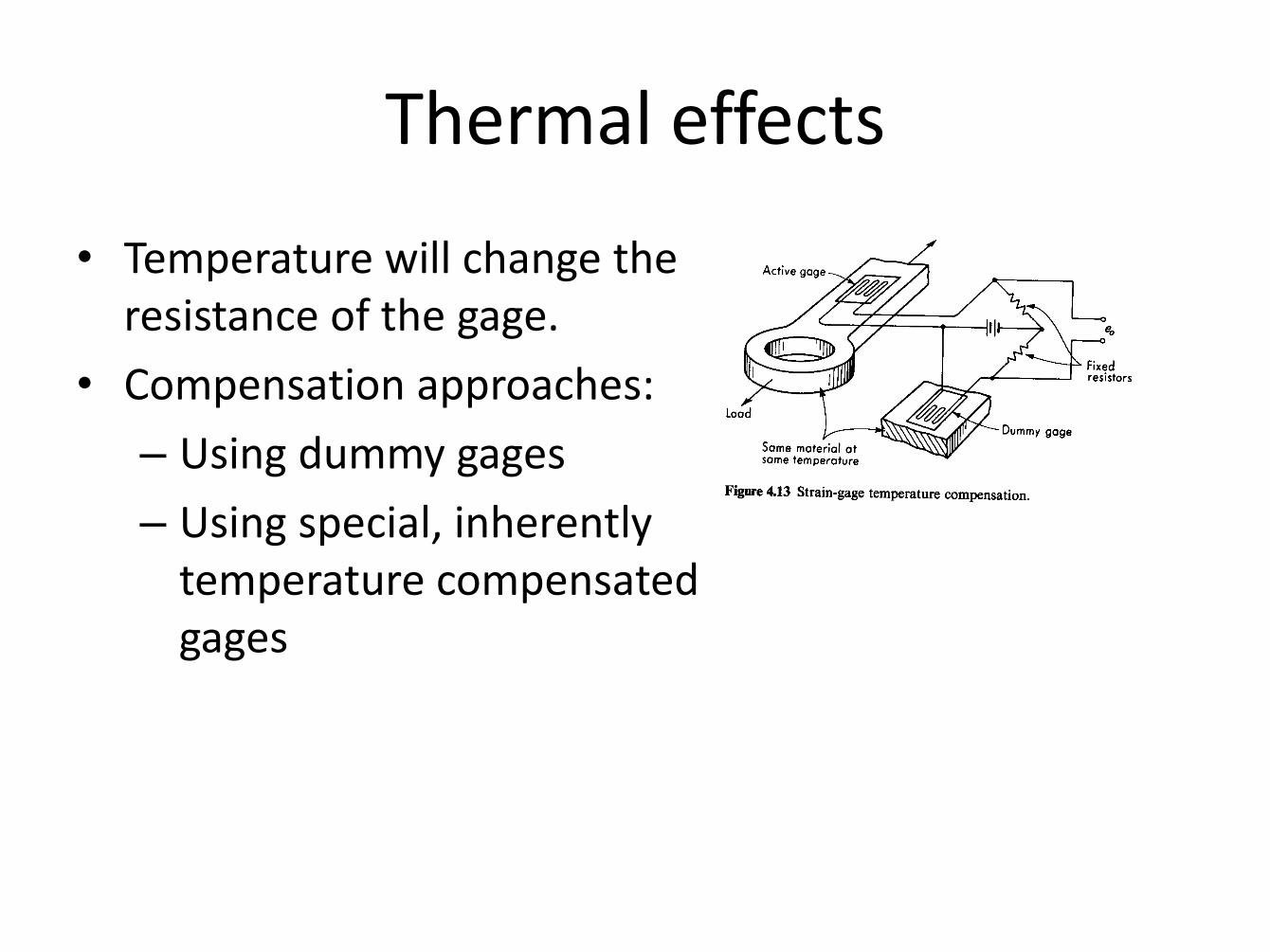
Thermal effects
• Temperature will change the resistance of the gage.
• Compensation approaches:
– Using dummy gages
– Using special, inherently temperature compensated gages

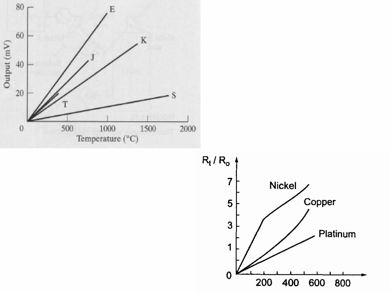
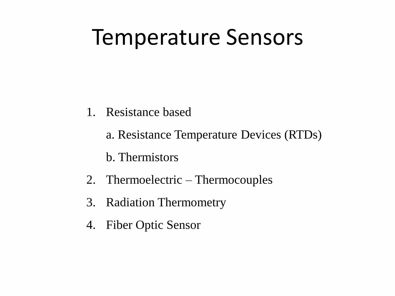
Temperature Sensors
1. Resistance based
a. Resistance Temperature Devices (RTDs)
b. Thermistors
2. Thermoelectric – Thermocouples
3. Radiation Thermometry
4. Fiber Optic Sensor
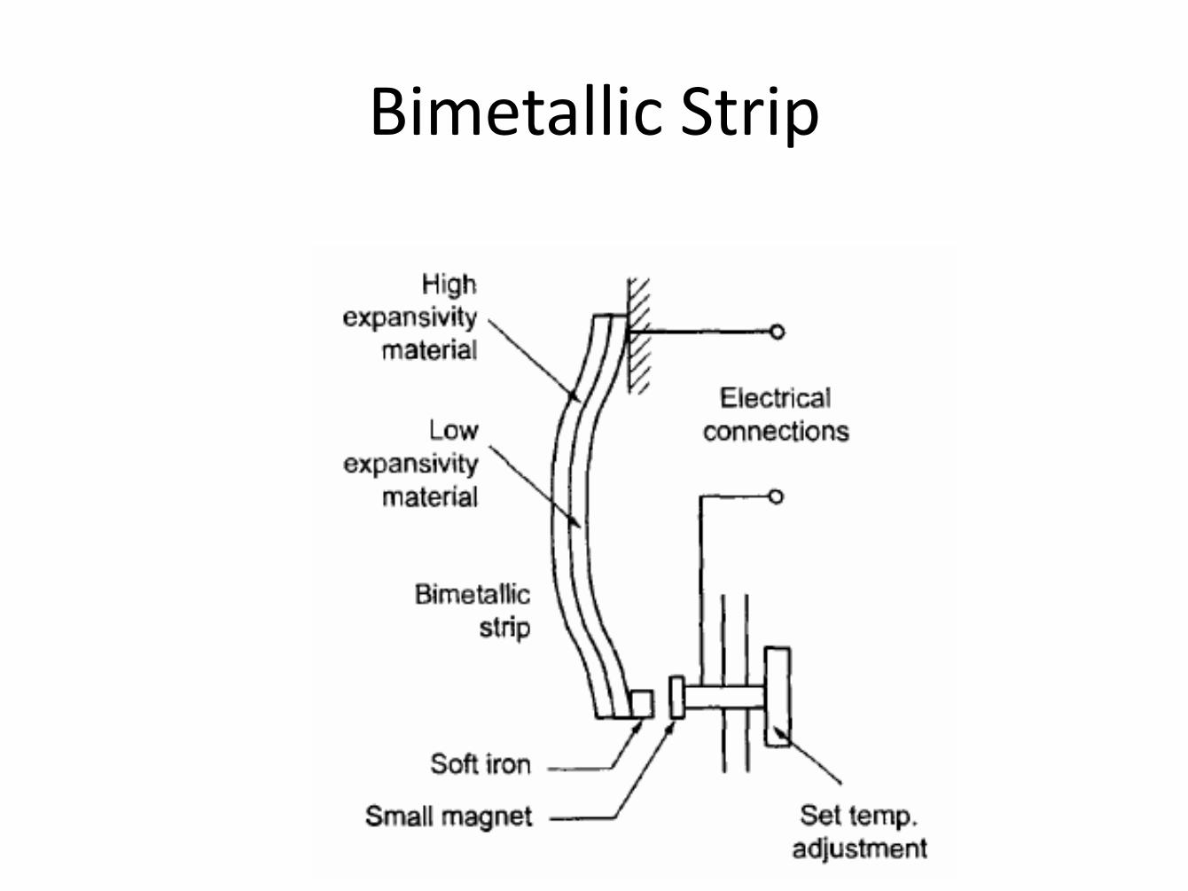
Bimetallic Strip
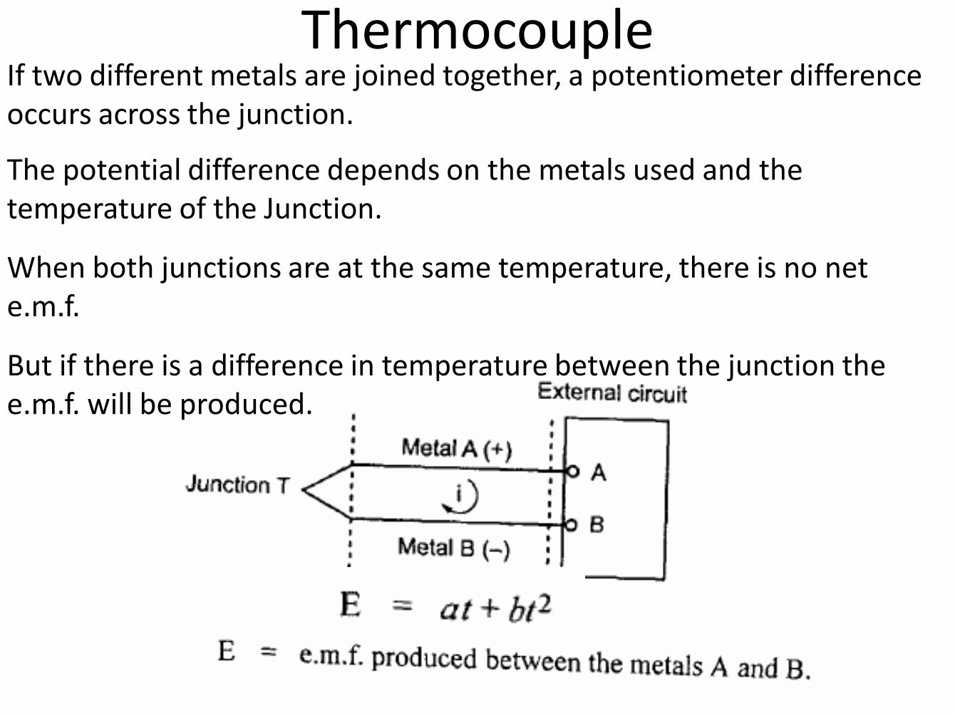
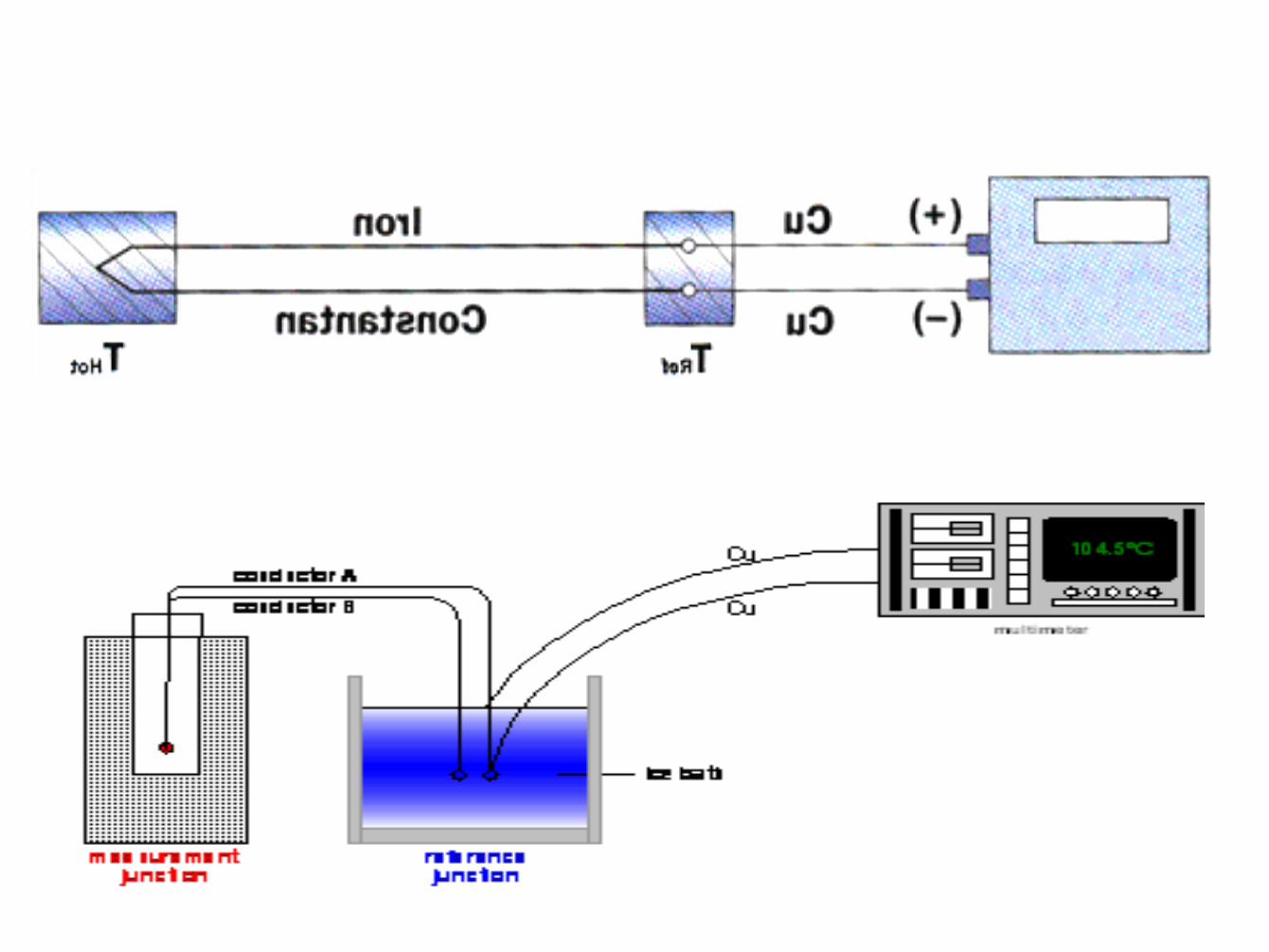
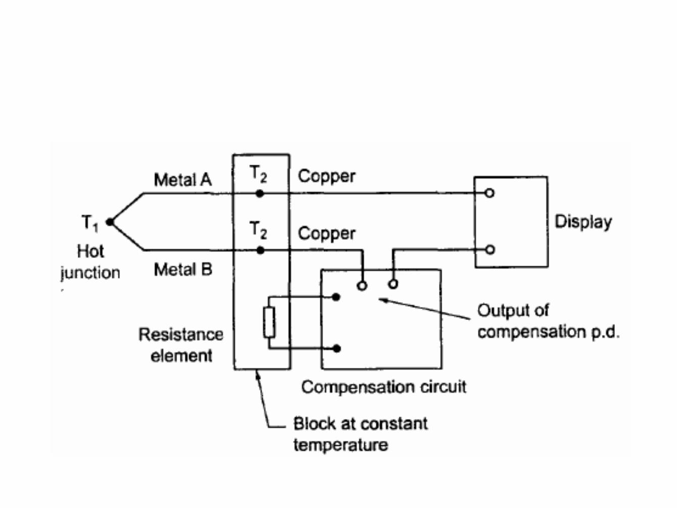
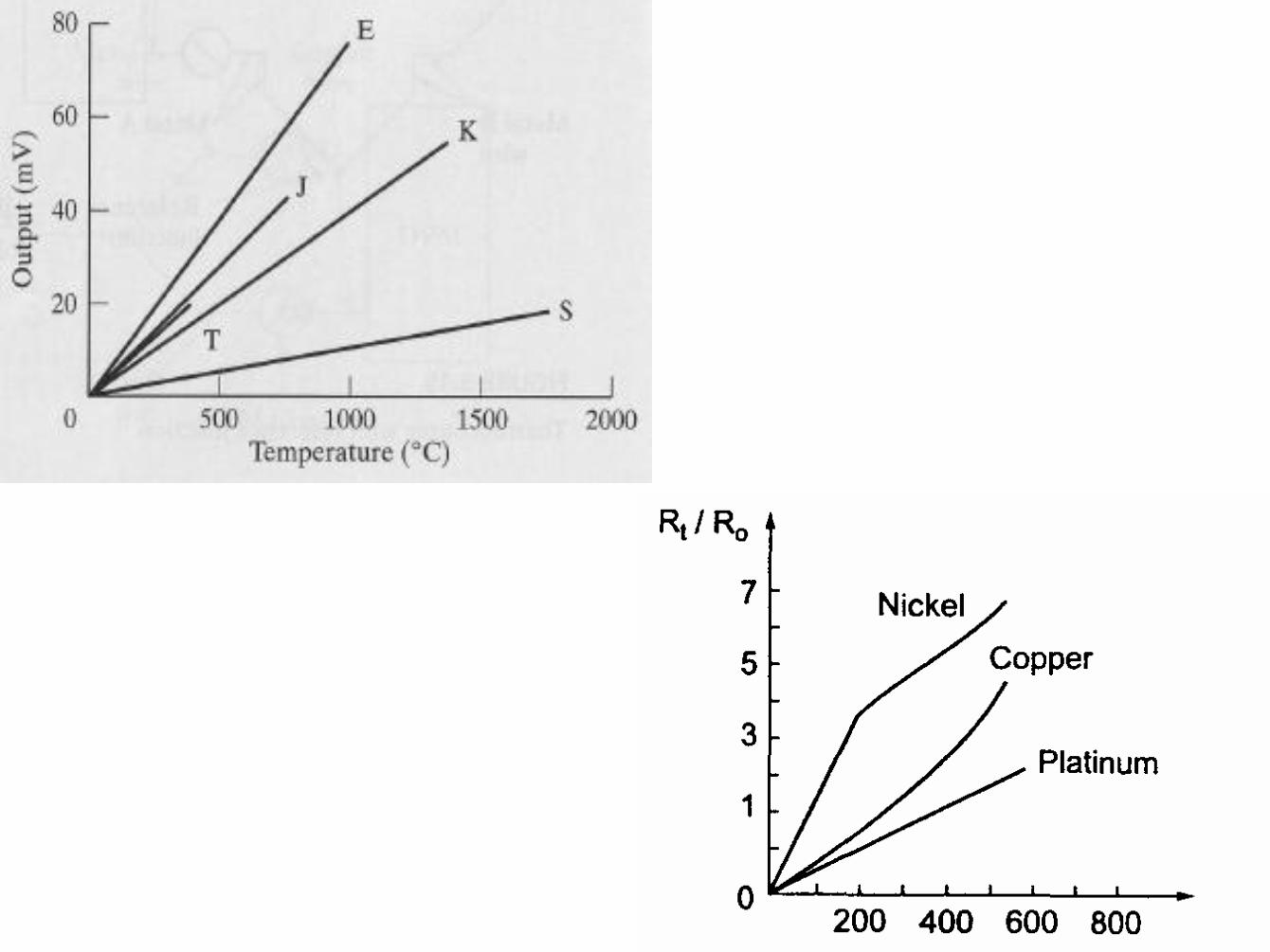
Thermocouple If two different metals are joined together, a potentiometer difference occurs across the junction.
The potential difference depends on the metals used and the temperature of the Junction.
When both junctions are at the same temperature, there is no net e.m.f.
But if there is a difference in temperature between the junction the e.m.f. will be produced.
Thermocouples
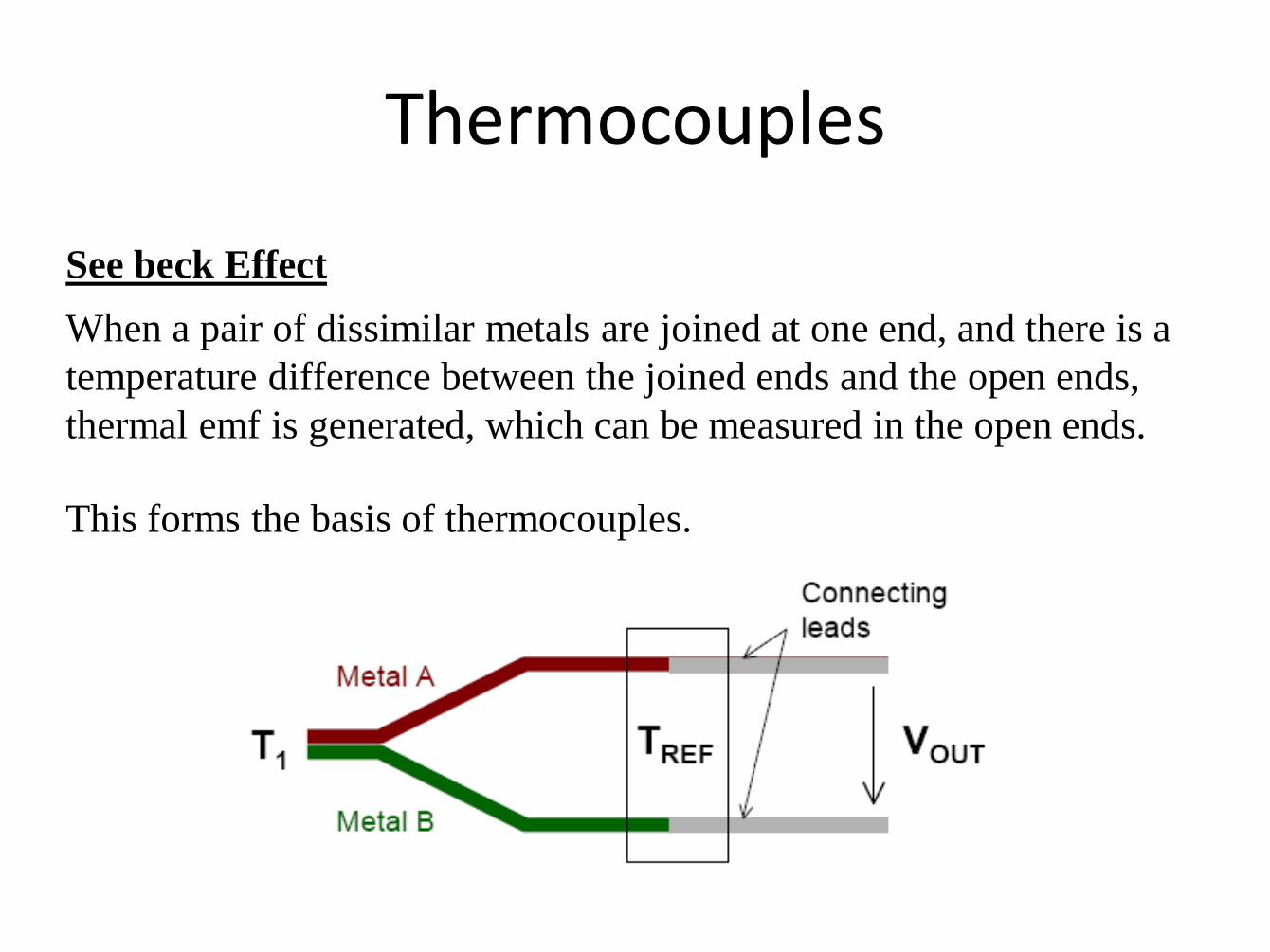
See beck Effect
When a pair of dissimilar metals are joined at one end, and there is a
temperature difference between the joined ends and the open ends,
thermal emf is generated, which can be measured in the open ends.
This forms the basis of thermocouples.
Temperature - Bimetallic strip
• Two or more layers of different coefficient of thermal expansion
• Used in standard thermostats in house industrial
• Delta = fn (T, A, B)
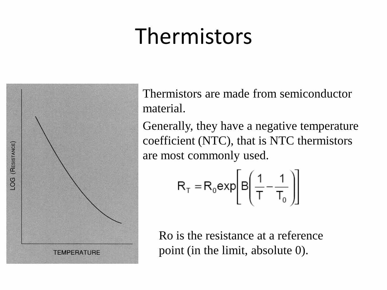
Thermistors
Thermistors are made from semiconductor
material.
Generally, they have a negative temperature
coefficient (NTC), that is NTC thermistors
are most commonly used.
Ro is the resistance at a reference
point (in the limit, absolute 0).
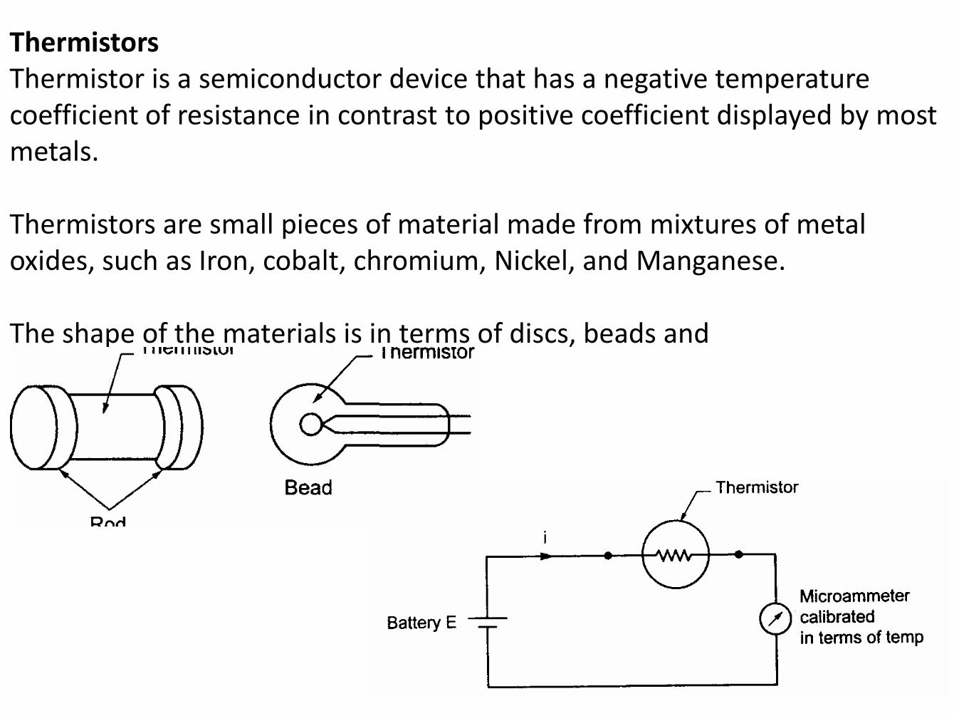
Thermistors Thermistor is a semiconductor device that has a negative temperature coefficient of resistance in contrast to positive coefficient displayed by most metals. Thermistors are small pieces of material made from mixtures of metal oxides, such as Iron, cobalt, chromium, Nickel, and Manganese. The shape of the materials is in terms of discs, beads and
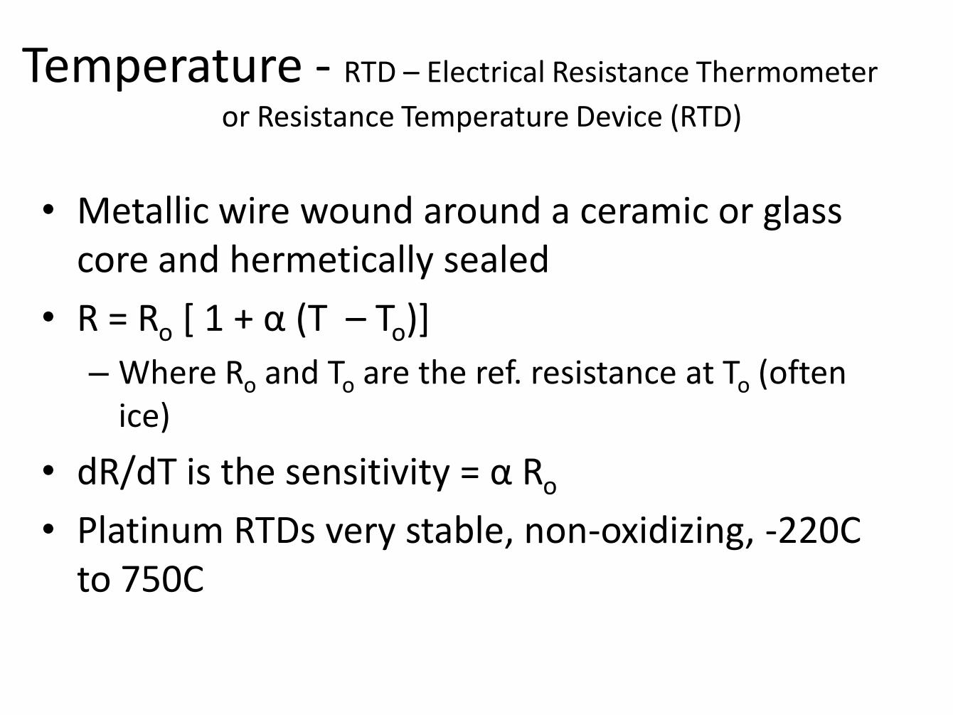
Temperature - RTD – Electrical Resistance Thermometer
or Resistance Temperature Device (RTD)
• Metallic wire wound around a ceramic or glass core and hermetically sealed
• R = Ro [ 1 + α (T – To)]
– Where Ro and To are the ref. resistance at To (often ice)
• dR/dT is the sensitivity = α Ro
• Platinum RTDs very stable, non-oxidizing, -220C to 750C

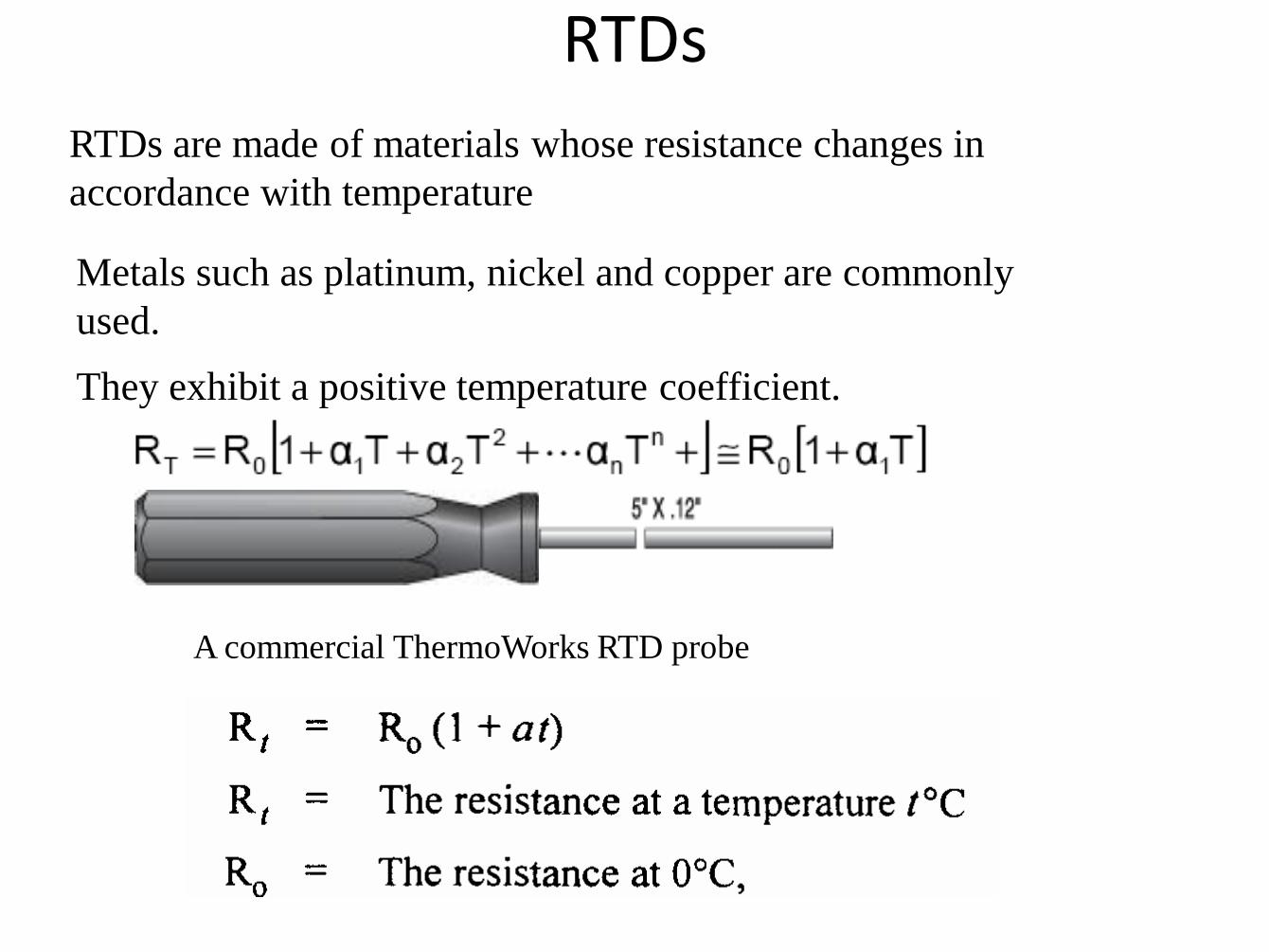
RTDs
RTDs are made of materials whose resistance changes in
accordance with temperature
Metals such as platinum, nickel and copper are commonly
used.
They exhibit a positive temperature coefficient.
A commercial ThermoWorks RTD probe
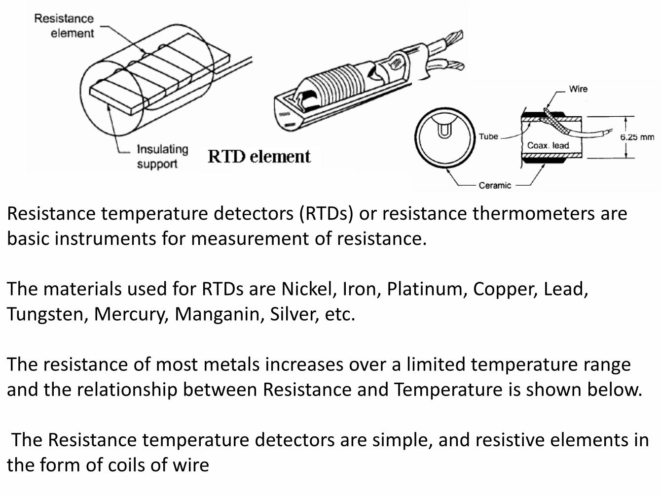
Resistance temperature detectors (RTDs) or resistance thermometers are basic instruments for measurement of resistance. The materials used for RTDs are Nickel, Iron, Platinum, Copper, Lead, Tungsten, Mercury, Manganin, Silver, etc. The resistance of most metals increases over a limited temperature range and the relationship between Resistance and Temperature is shown below. The Resistance temperature detectors are simple, and resistive elements in the form of coils of wire
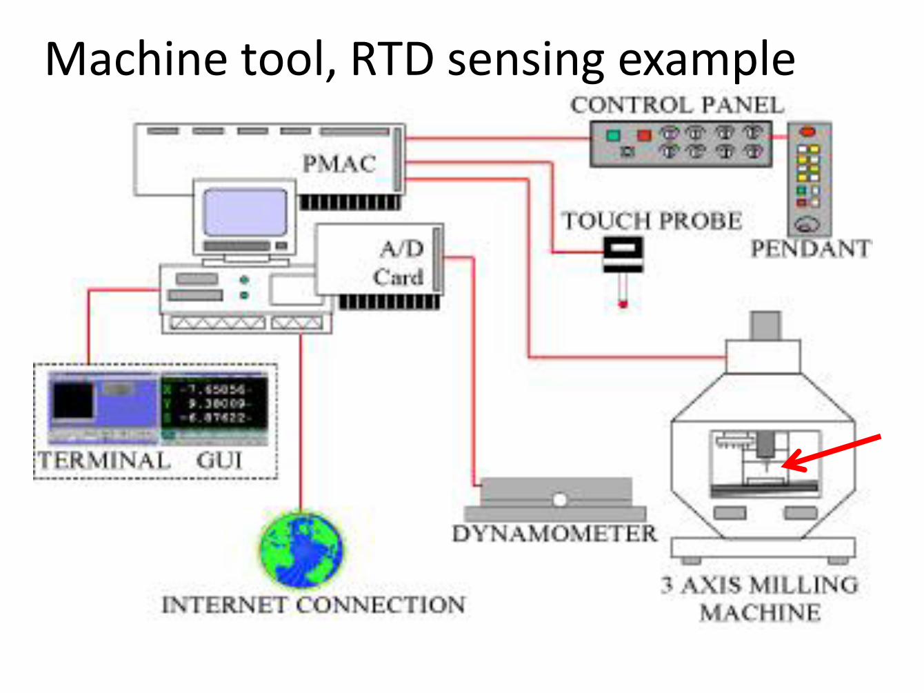
Machine tool, RTD sensing example

The temperature sensor was placed on the lower face of the tool (in a previously infeasible location)


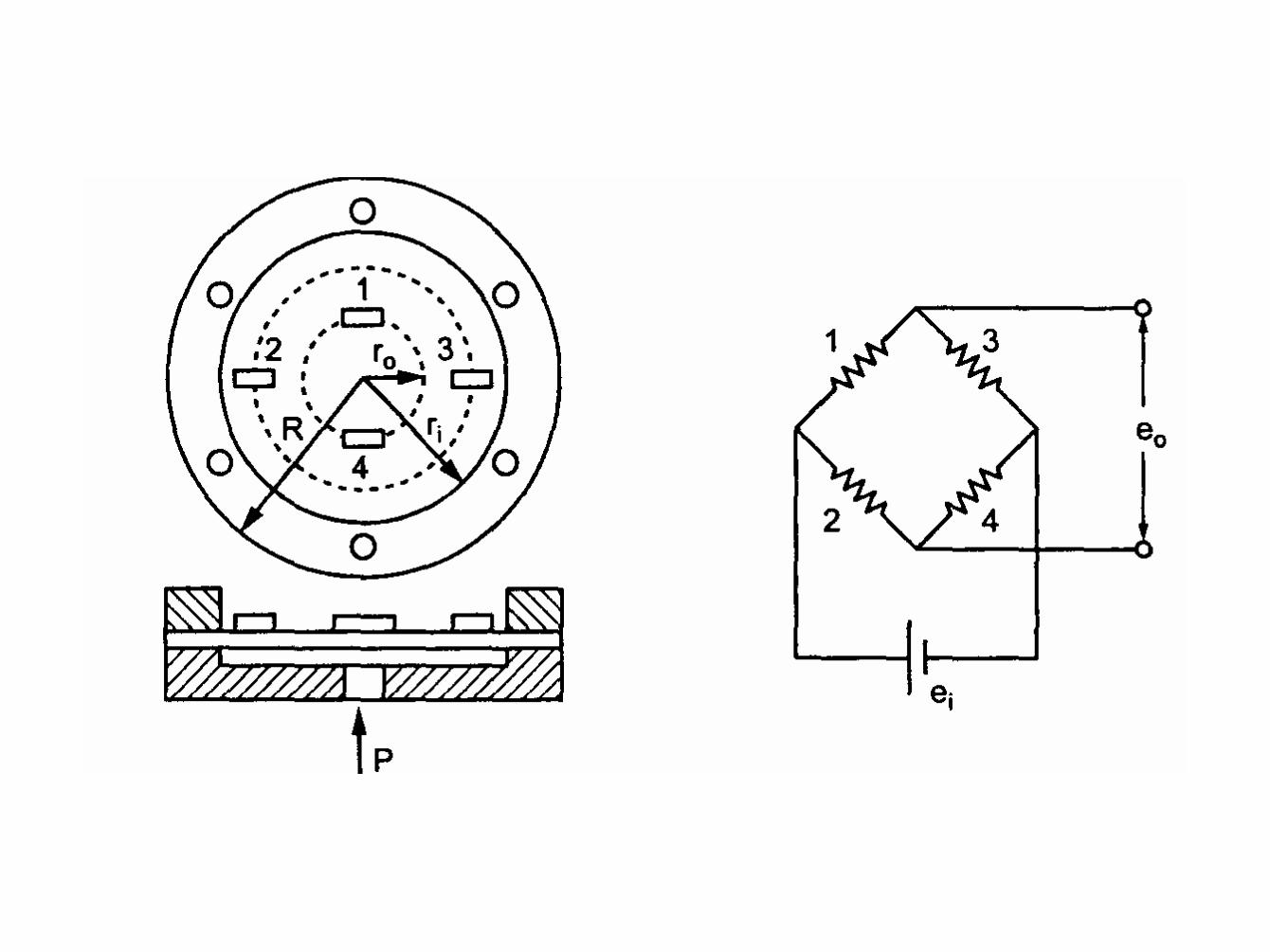
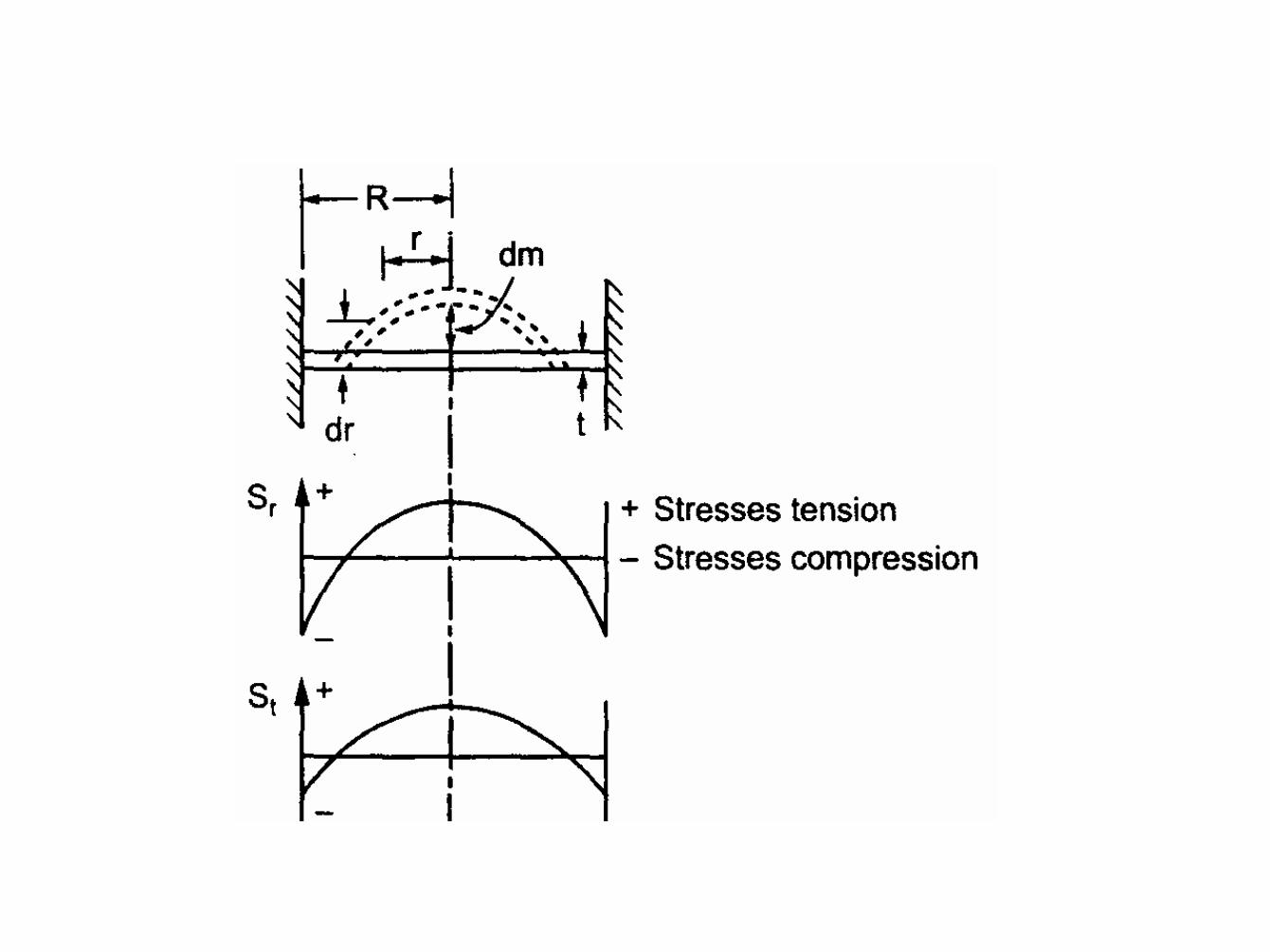
Fluid Pressure Sensor • Diaphragms
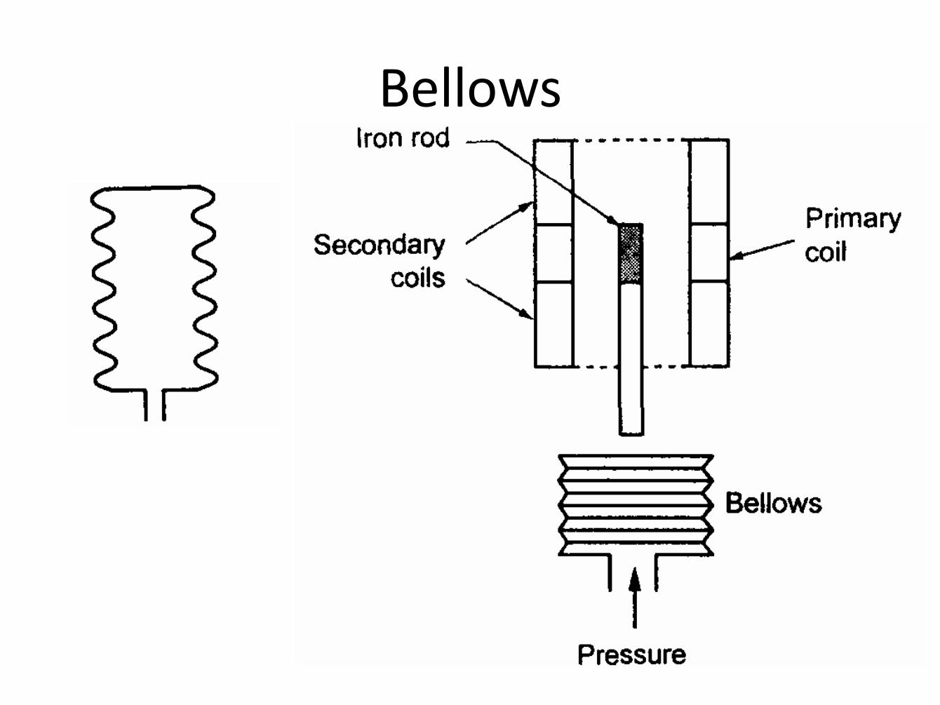
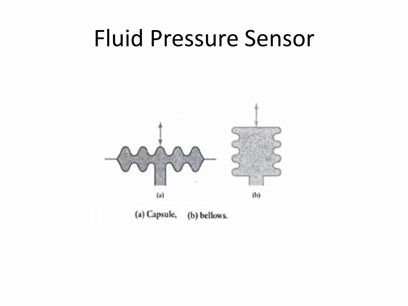
Bellows
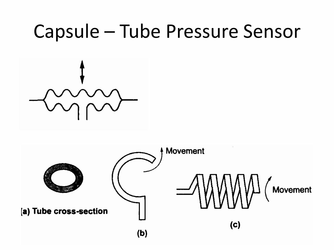
Capsule – Tube Pressure Sensor
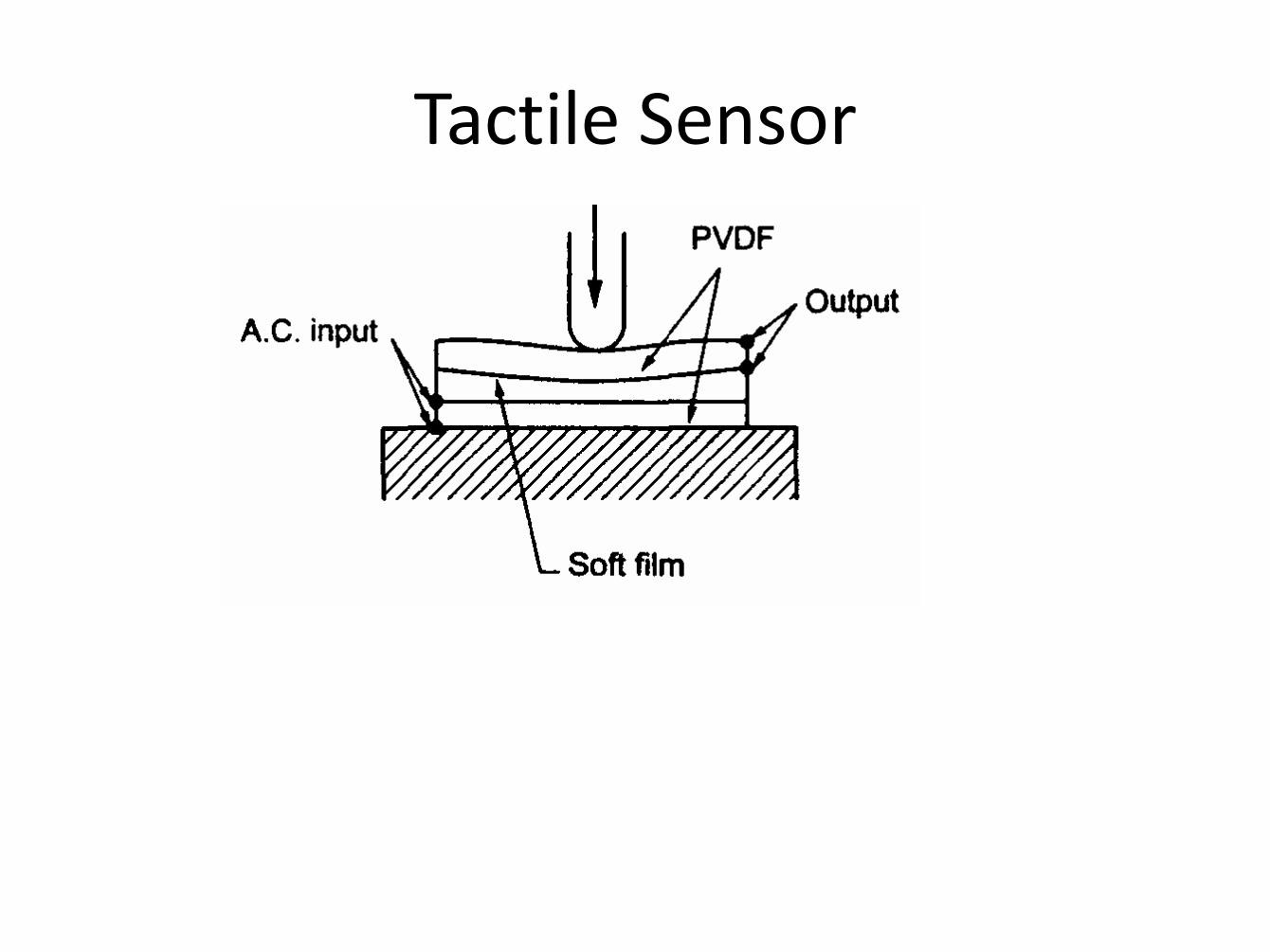
Tactile Sensor
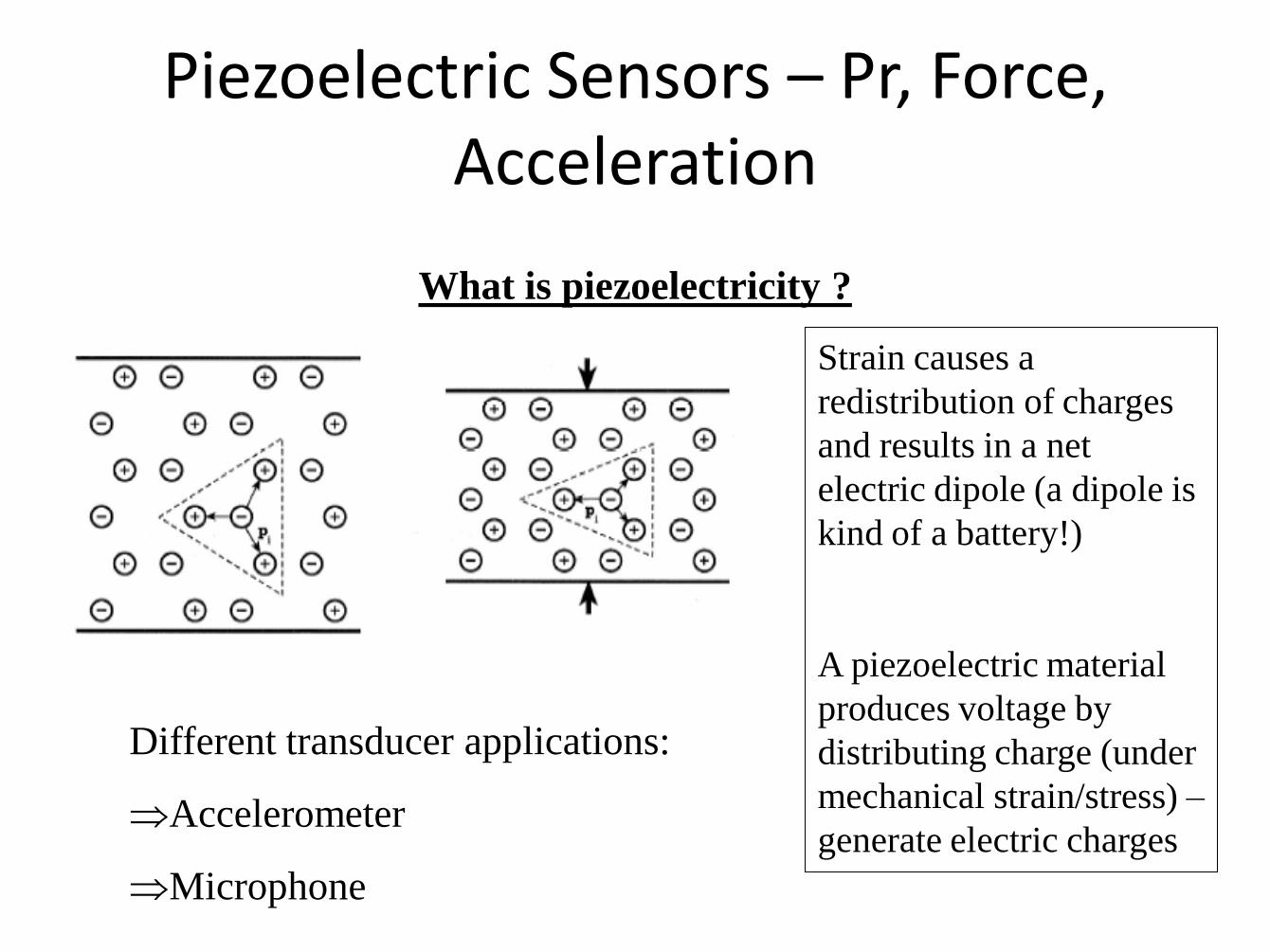
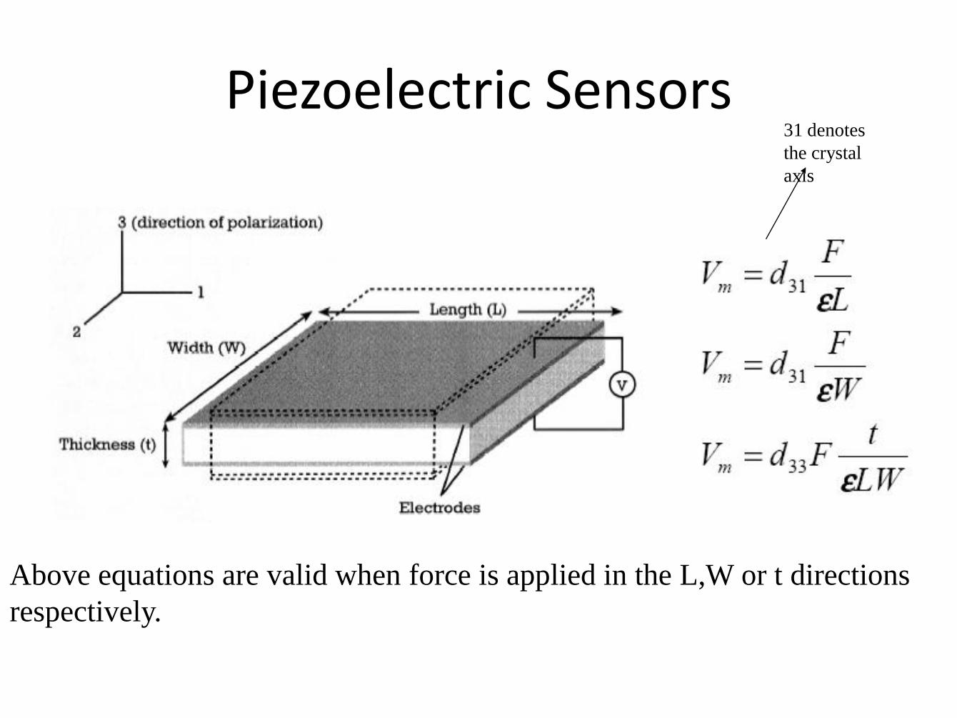
Piezoelectric Sensors
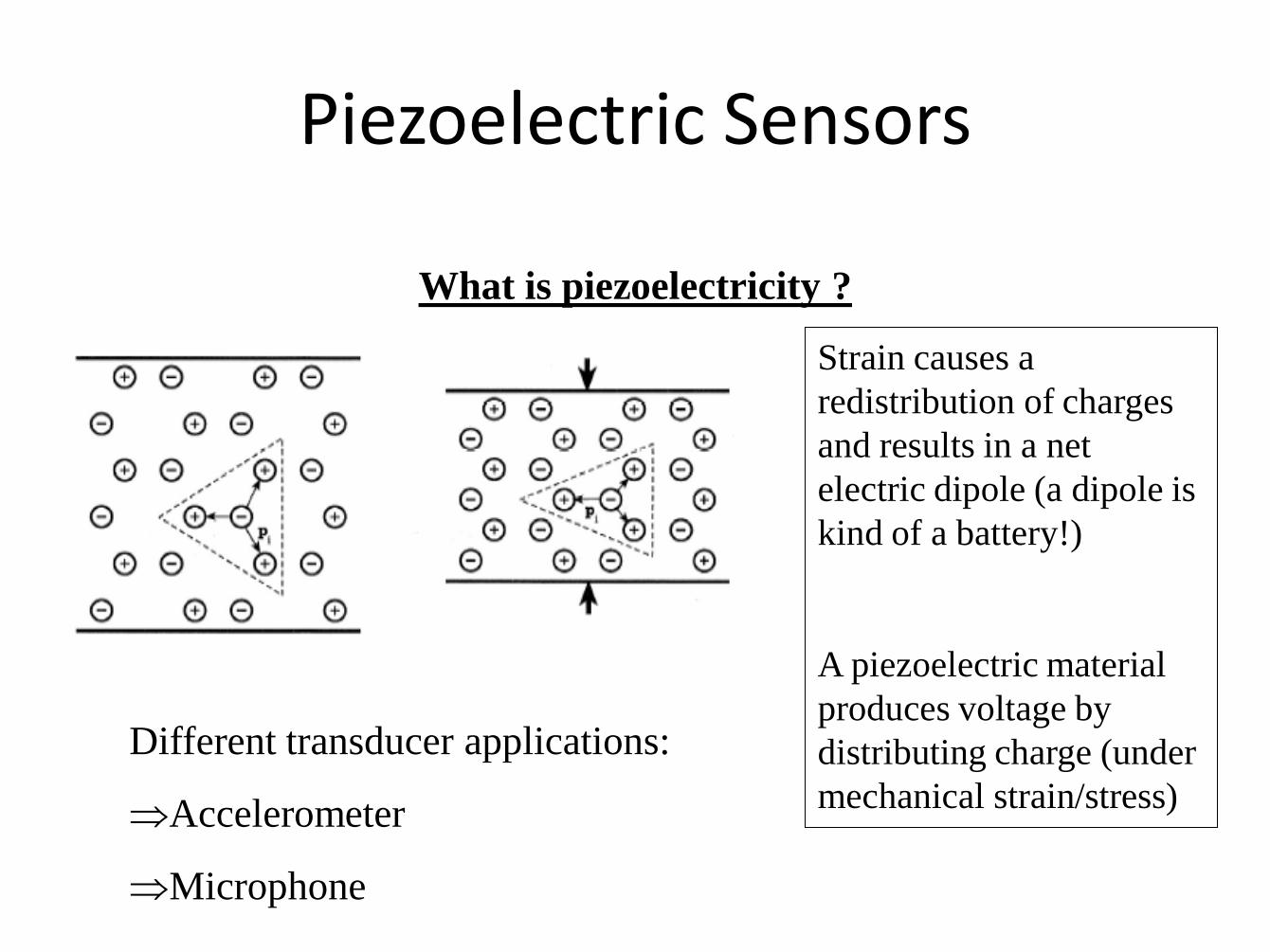
What is piezoelectricity ?
Strain causes a
redistribution of charges
and results in a net
electric dipole (a dipole is
kind of a battery!)
A piezoelectric material
produces voltage by
distributing charge (under
mechanical strain/stress)
Different transducer applications:
Accelerometer
Microphone

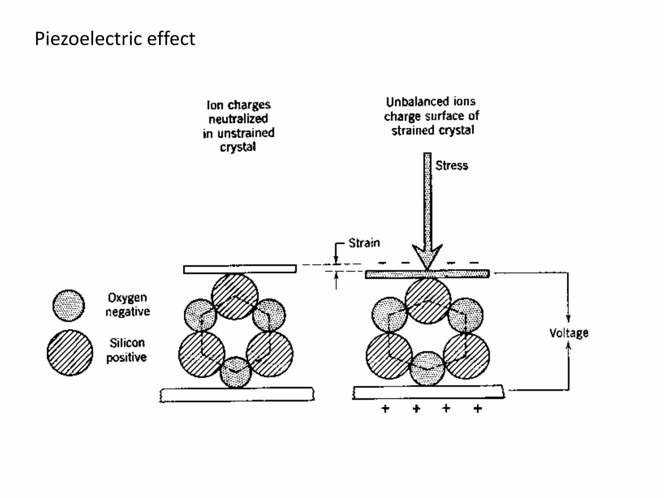
Piezoelectric effect
Vacuum
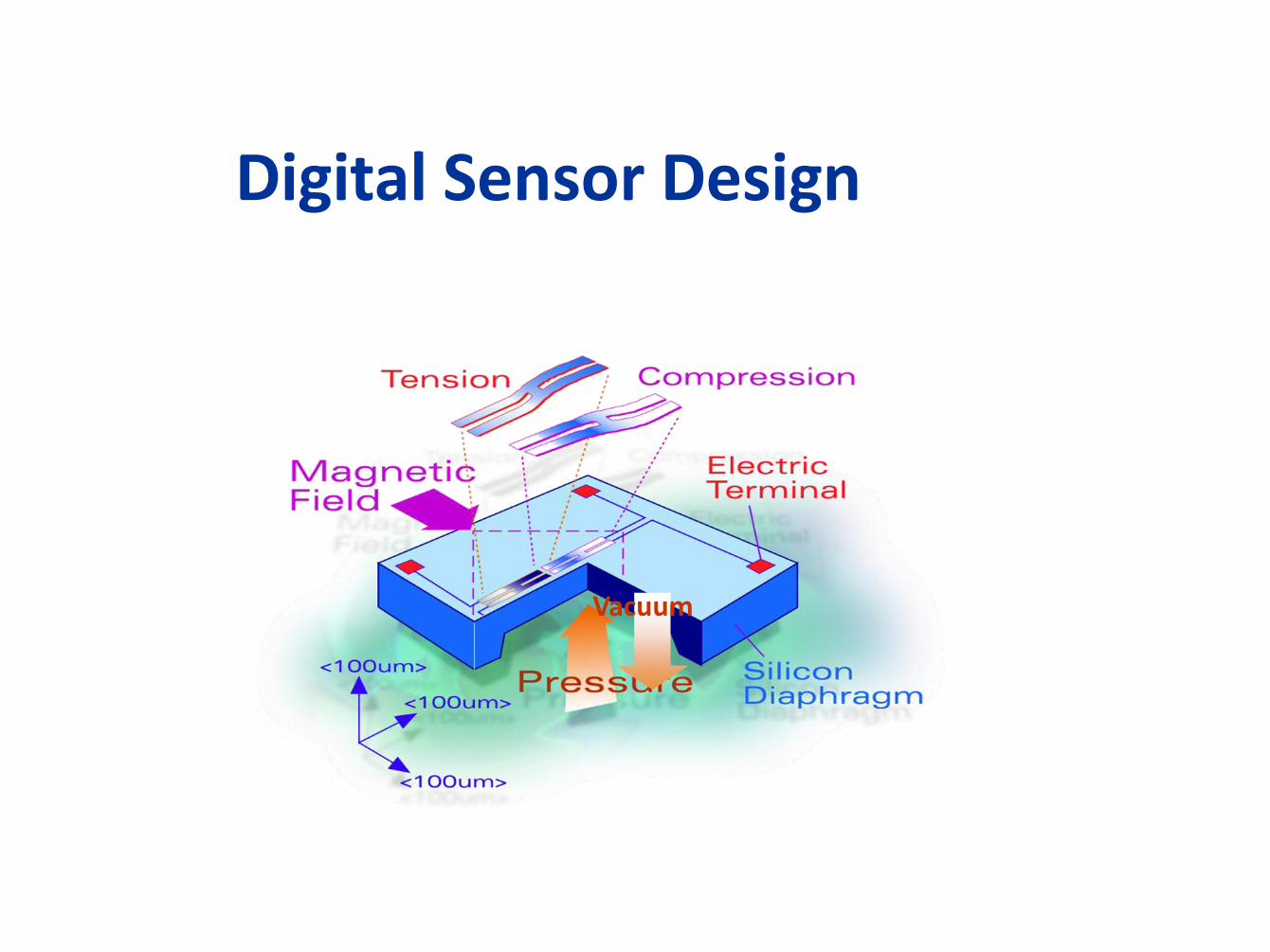
Digital Sensor Design
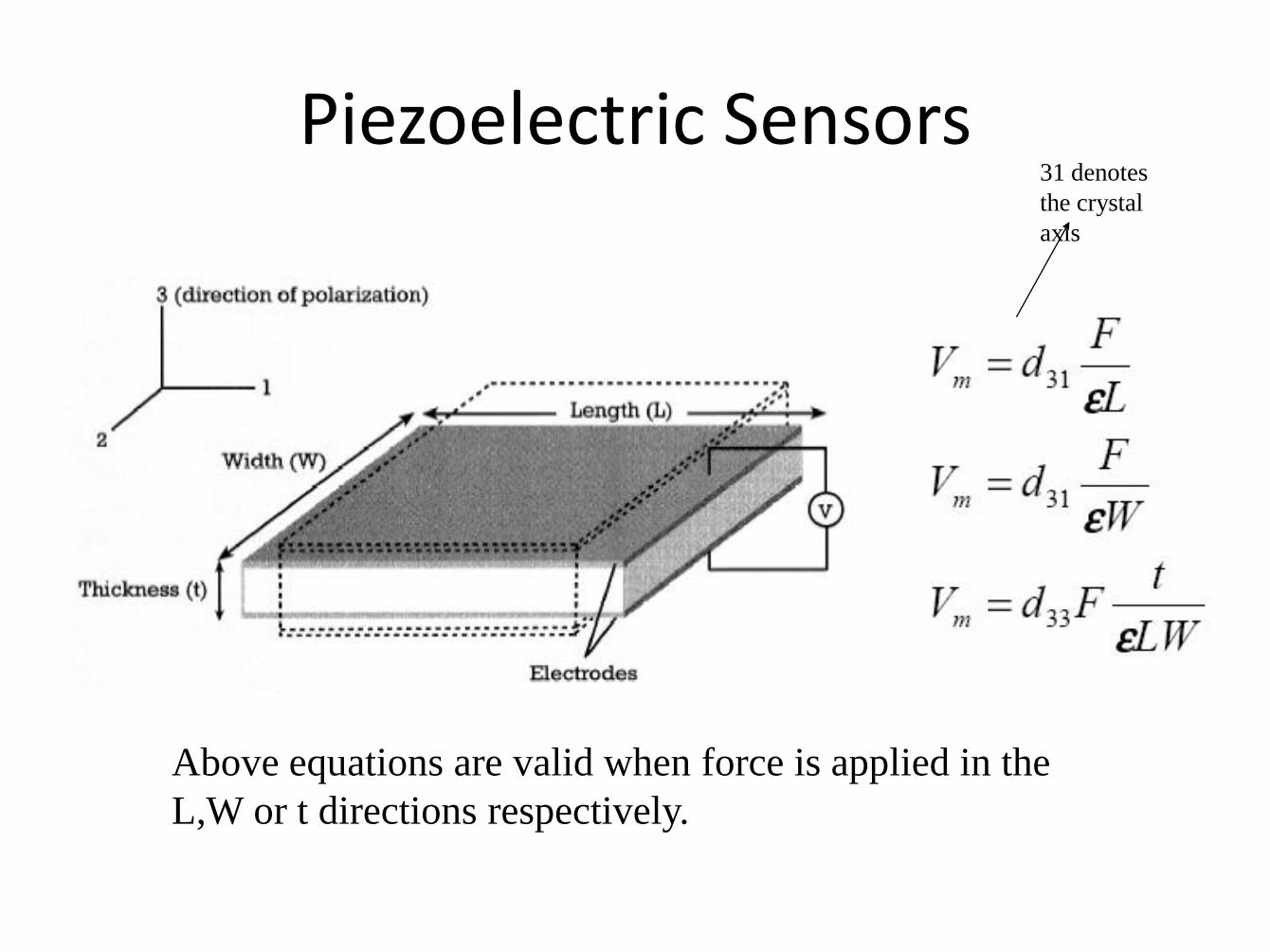
Piezoelectric Sensors
Above equations are valid when force is applied in the
L,W or t directions respectively.
31 denotes
the crystal
axis

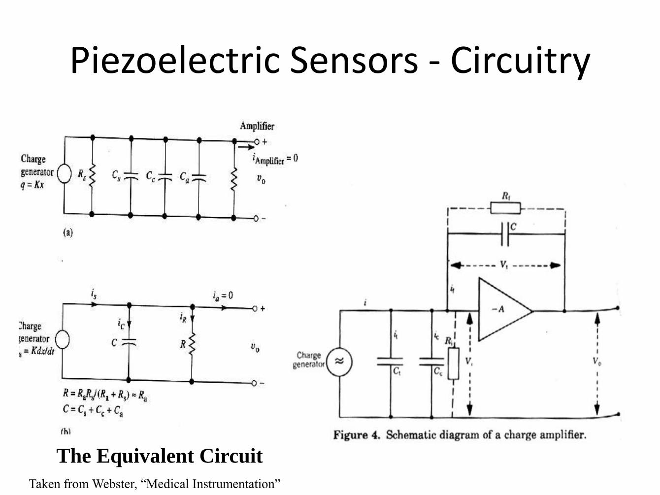
Piezoelectric Sensors - Circuitry
The Equivalent Circuit
Taken from Webster, “Medical Instrumentation”

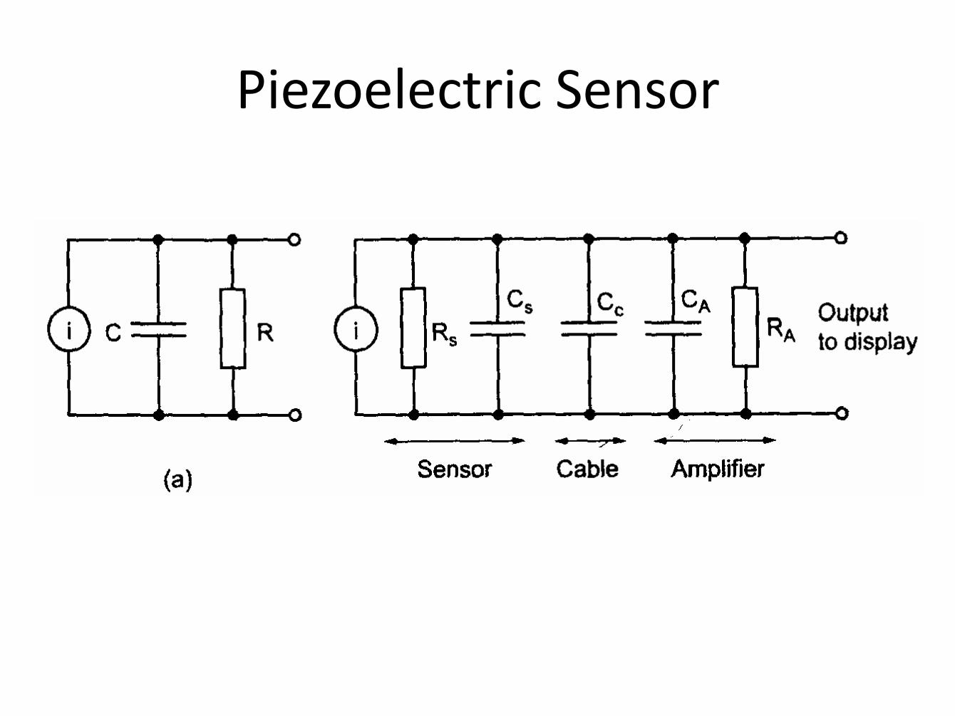
Piezoelectric Sensor
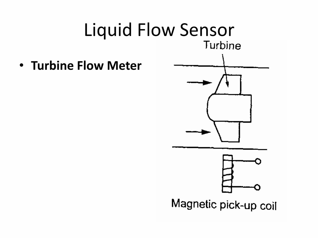
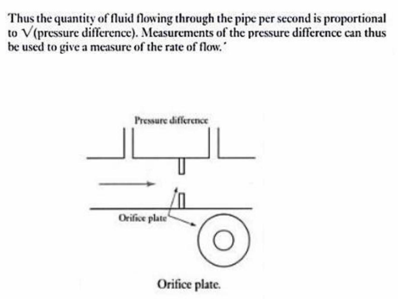
Liquid Flow Sensor
• Turbine Flow Meter
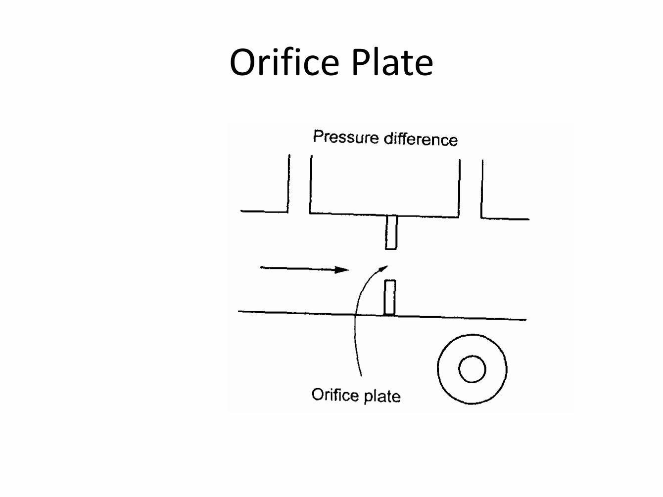
Orifice Plate
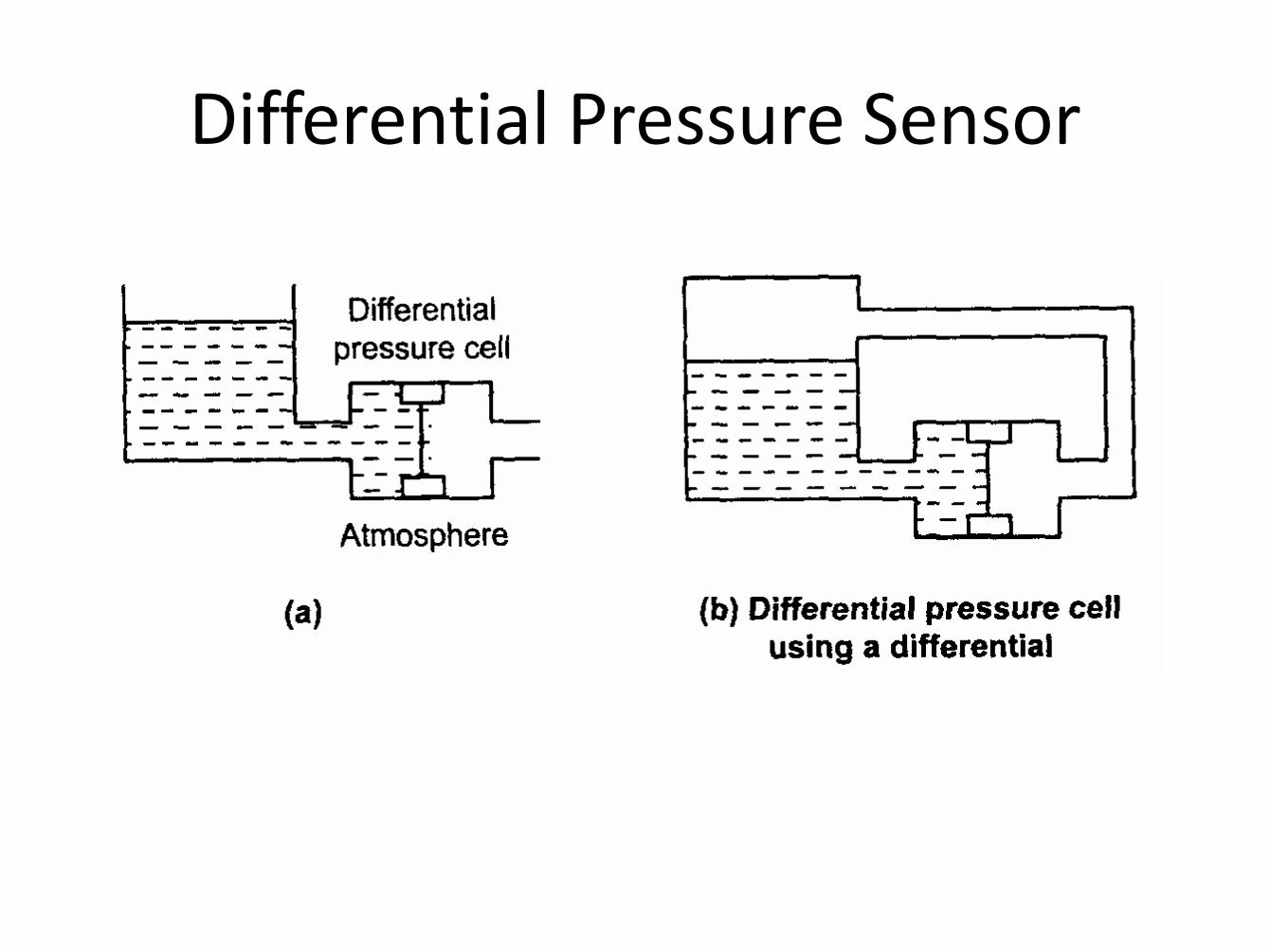
Differential Pressure Sensor
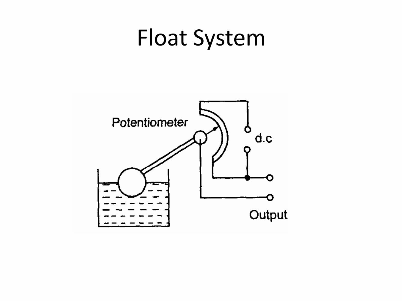
Float System
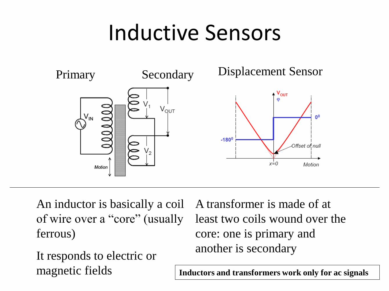
Inductive Sensors
An inductor is basically a coil
of wire over a “core” (usually
ferrous)
It responds to electric or
magnetic fields
A transformer is made of at
least two coils wound over the
core: one is primary and
another is secondary
Primary Secondary Displacement Sensor
Inductors and transformers work only for ac signals
Inductive Sensors - LVDT
LVDT Linear Variable
Differential Transformer Taken from
http://www.pages.drexel.edu/~pyo22/mem351-2004/lecture04/pp062-073lvdt.pdf
An LVDT is used as a sensitive displacement sensor: for example, in a cardiac assist device or a
basic research project to study displacement produced by a contracting muscle.
Inductive displacement sensors (cont)
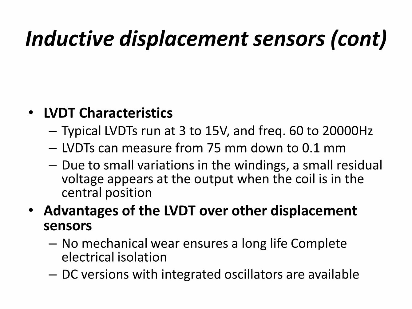
• LVDT Characteristics
– Typical LVDTs run at 3 to 15V, and freq. 60 to 20000Hz – LVDTs can measure from 75 mm down to 0.1 mm – Due to small variations in the windings, a small residual
voltage appears at the output when the coil is in the central position
• Advantages of the LVDT over other displacement sensors – No mechanical wear ensures a long life Complete
electrical isolation – DC versions with integrated oscillators are available
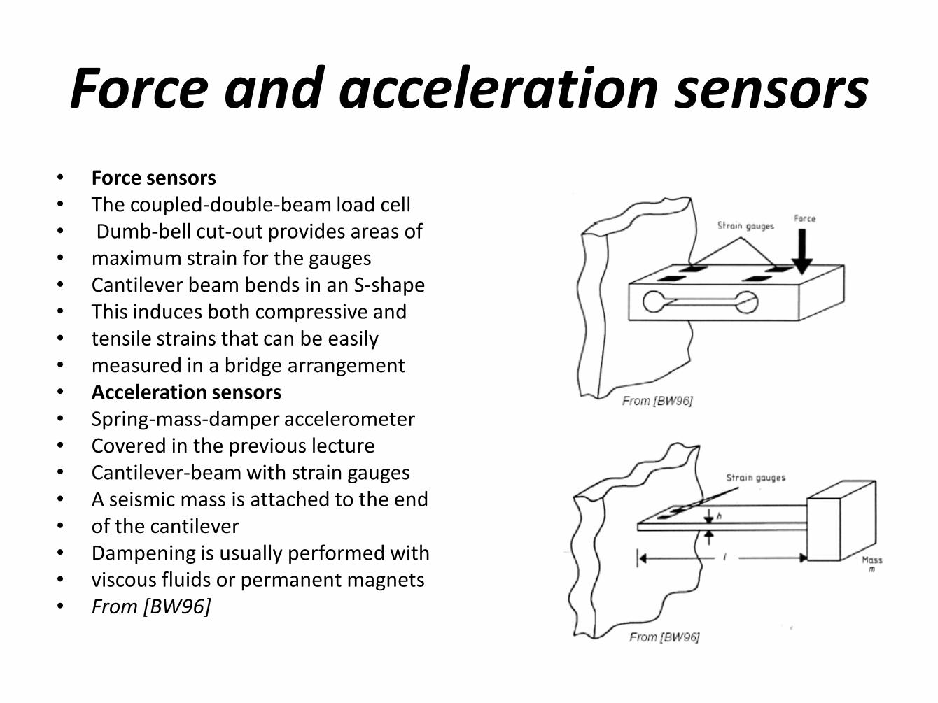
Force and acceleration sensors • Force sensors • The coupled-double-beam load cell • Dumb-bell cut-out provides areas of • maximum strain for the gauges • Cantilever beam bends in an S-shape • This induces both compressive and • tensile strains that can be easily • measured in a bridge arrangement • Acceleration sensors • Spring-mass-damper accelerometer • Covered in the previous lecture • Cantilever-beam with strain gauges • A seismic mass is attached to the end • of the cantilever • Dampening is usually performed with • viscous fluids or permanent magnets • From [BW96]
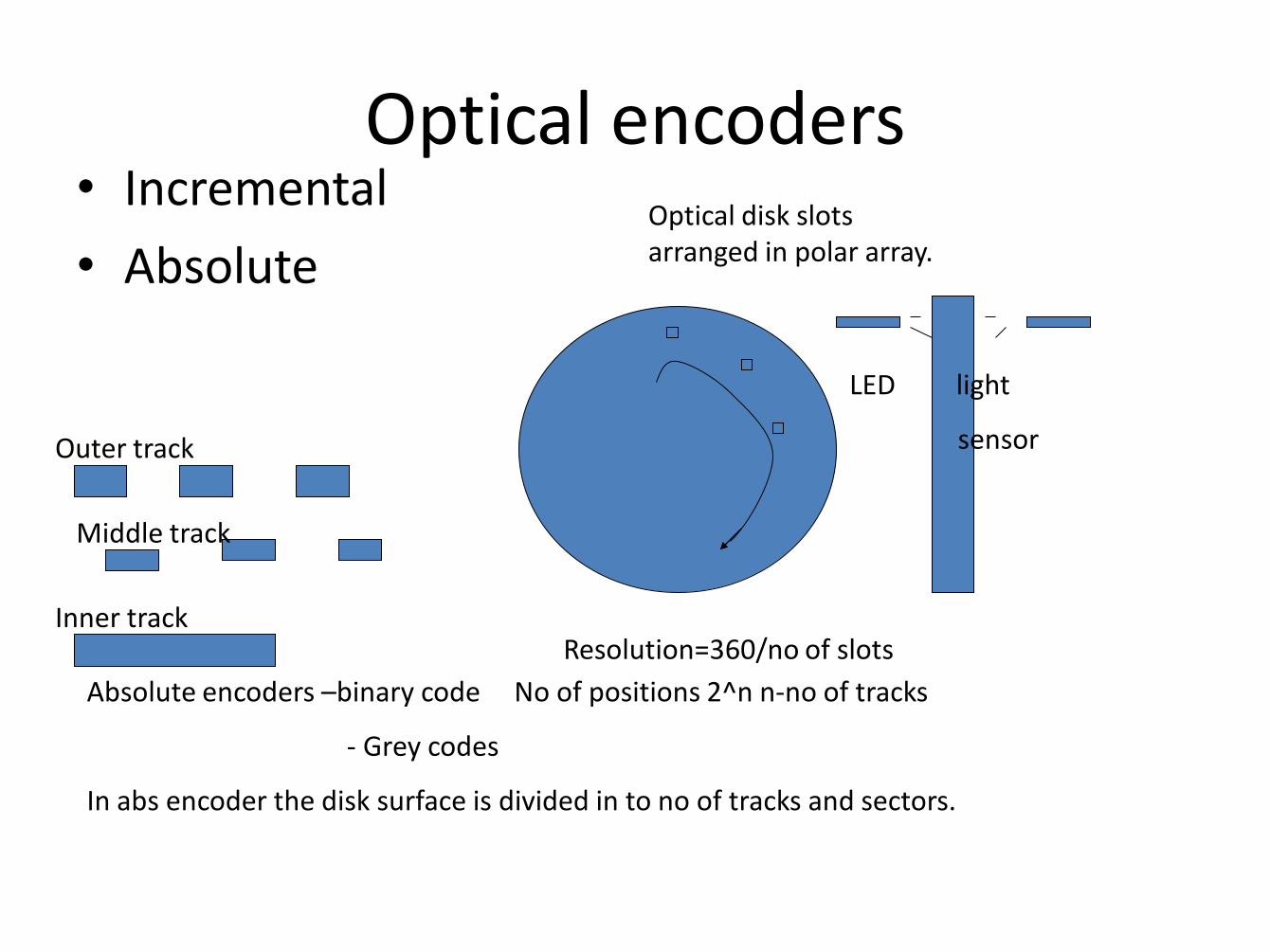
Optical encoders • Incremental
• Absolute Optical disk slots arranged in polar array.
LED light
sensor Outer track
Middle track
Inner track Resolution=360/no of slots
Absolute encoders –binary code No of positions 2^n n-no of tracks
- Grey codes
In abs encoder the disk surface is divided in to no of tracks and sectors.
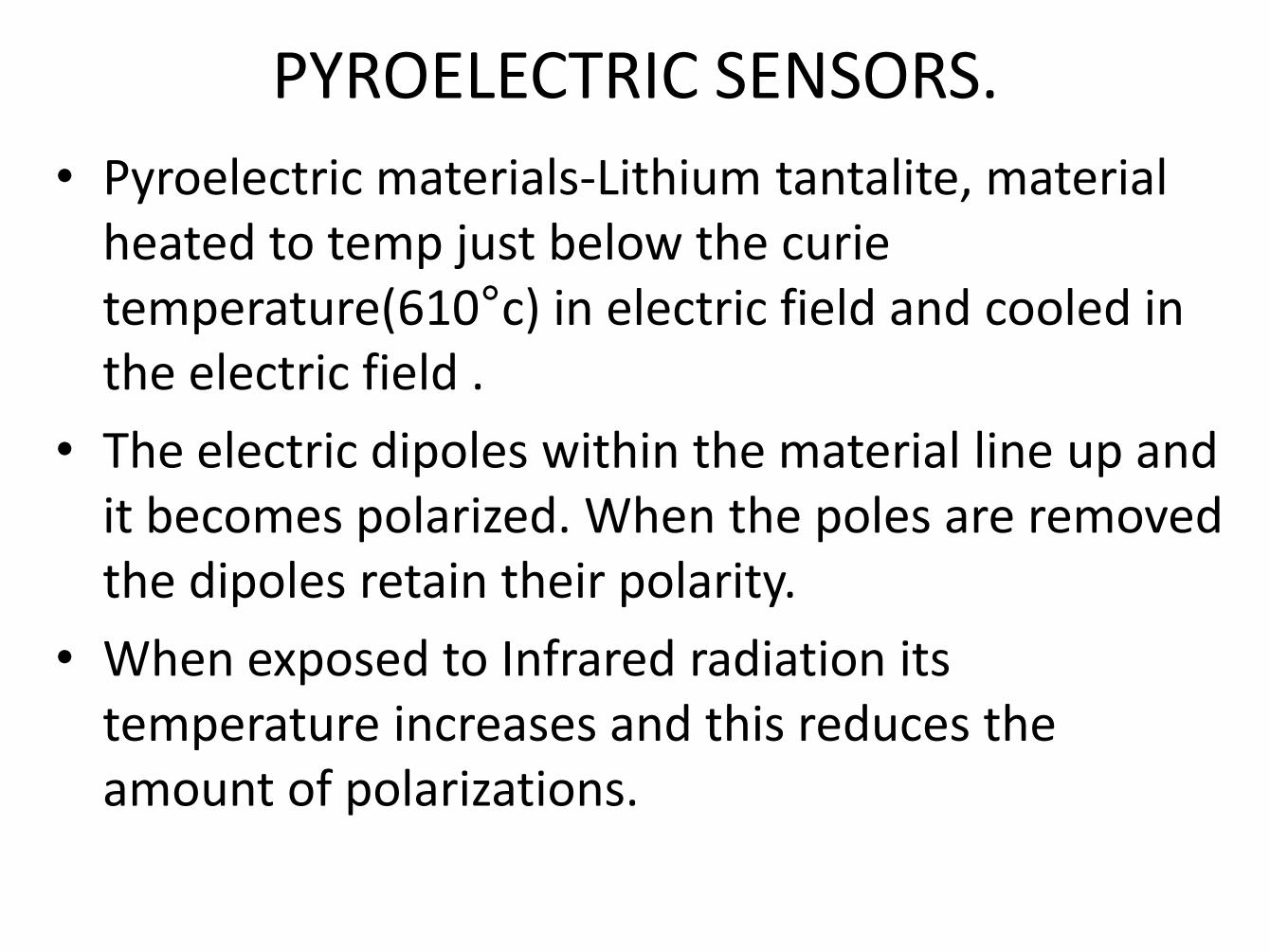
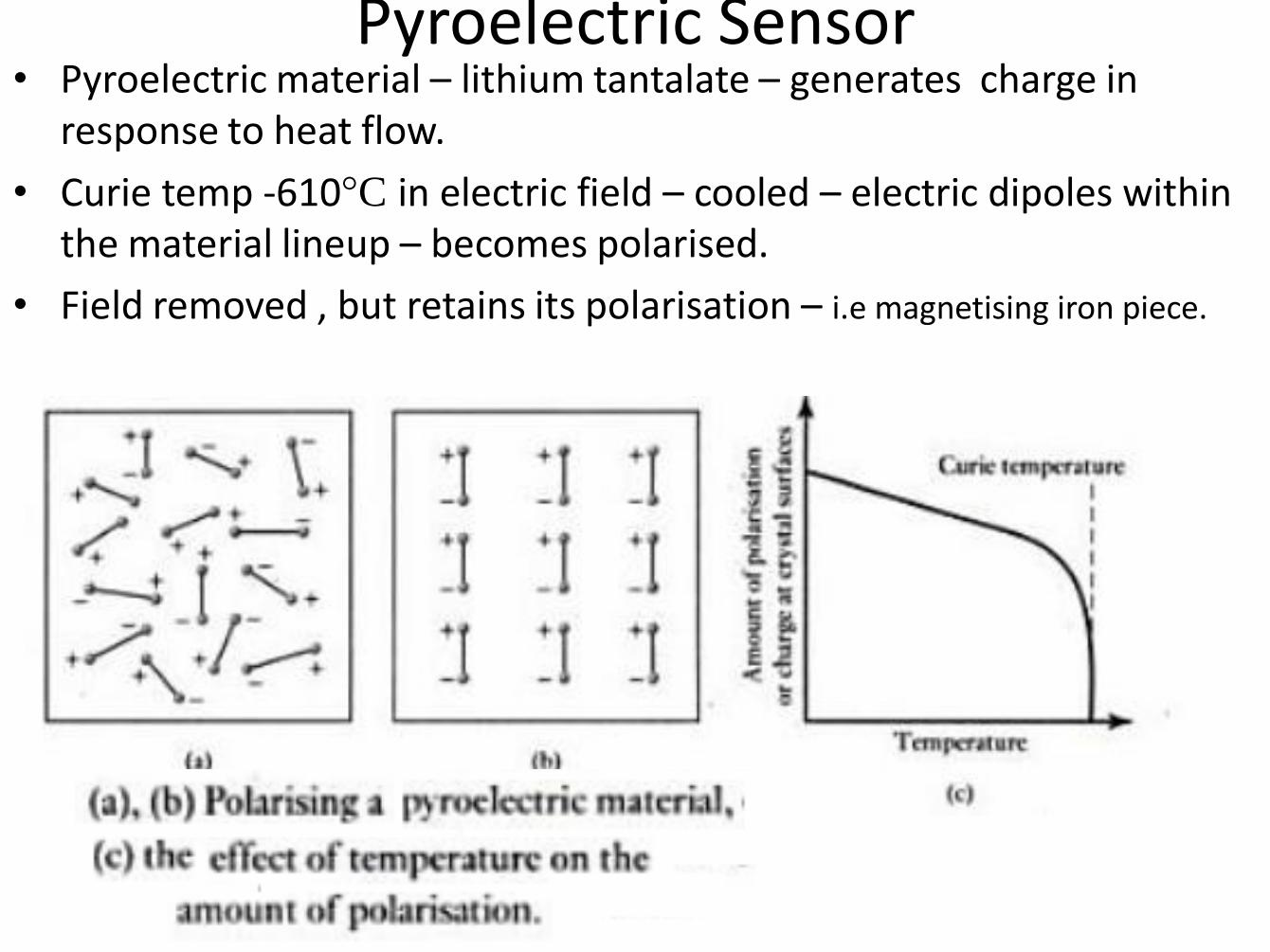
PYROELECTRIC SENSORS. • Pyroelectric materials-Lithium tantalite, material
heated to temp just below the curie temperature(610°c) in electric field and cooled in the electric field .
• The electric dipoles within the material line up and it becomes polarized. When the poles are removed the dipoles retain their polarity.
• When exposed to Infrared radiation its temperature increases and this reduces the amount of polarizations.
Pyroelectric….
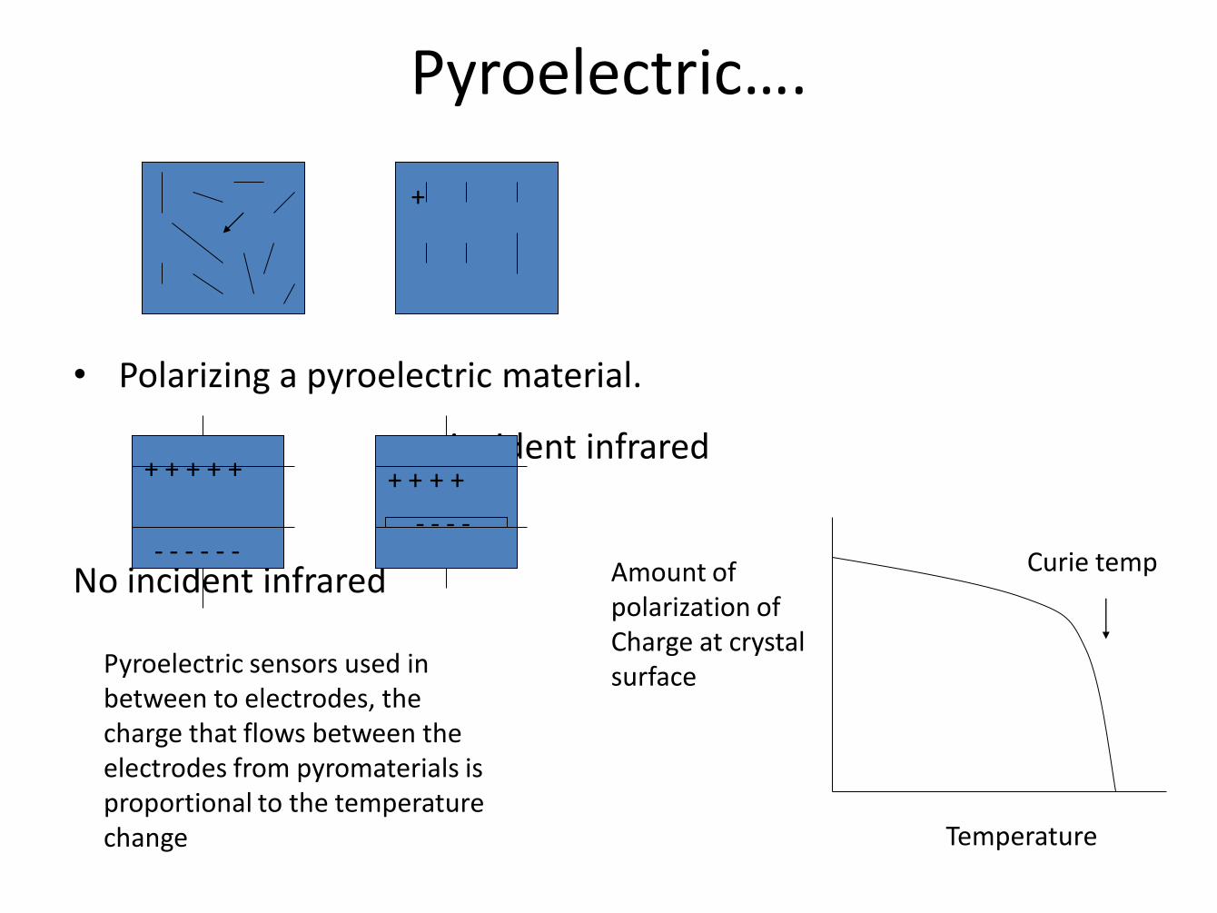
• Polarizing a pyroelectric material.
incident infrared
No incident infrared
+
+ + + + +
- - - - - -
+ + + +
- - - -
Amount of polarization of Charge at crystal surface
Curie temp
Temperature
Pyroelectric sensors used in between to electrodes, the charge that flows between the electrodes from pyromaterials is proportional to the temperature change
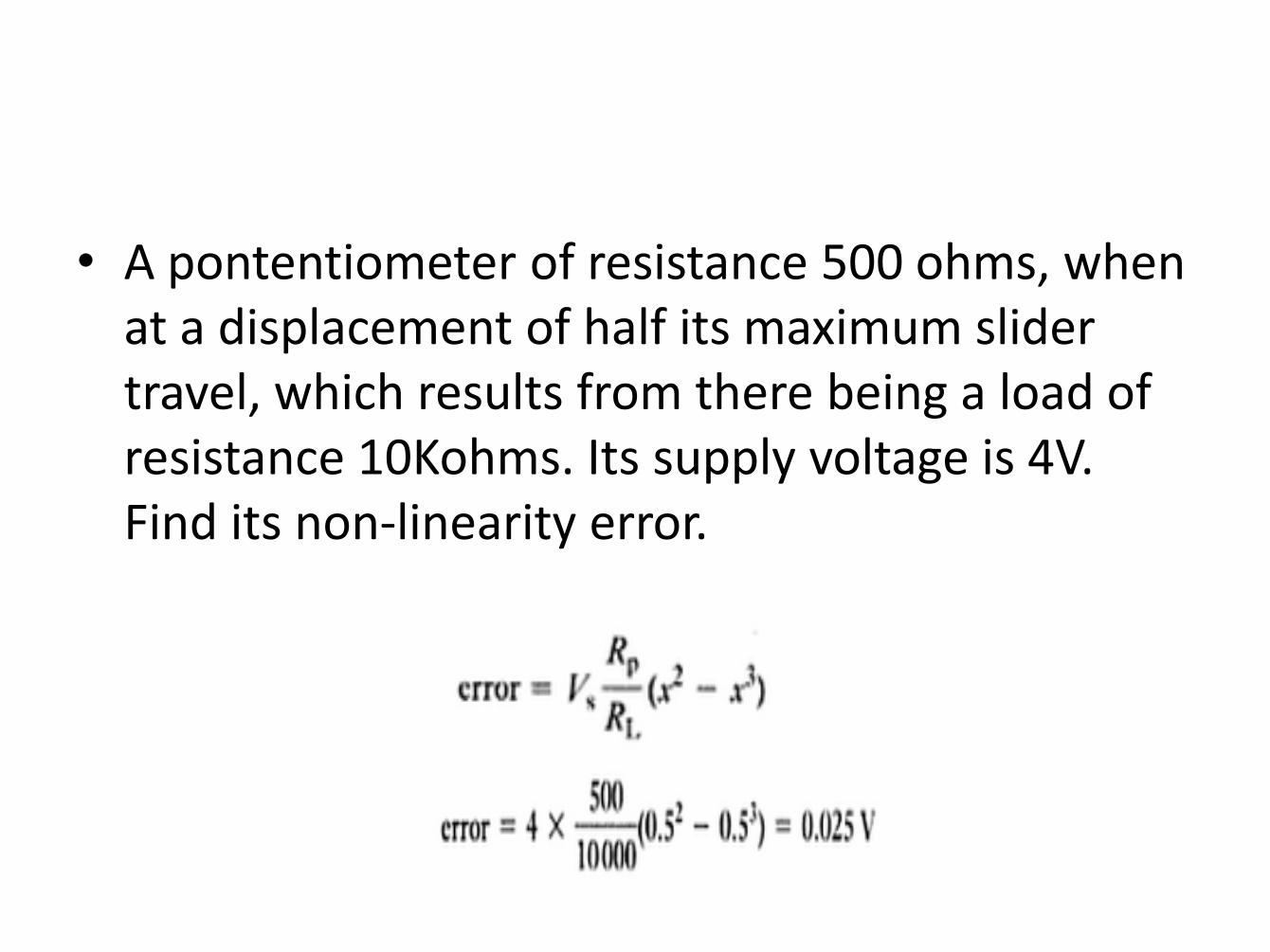
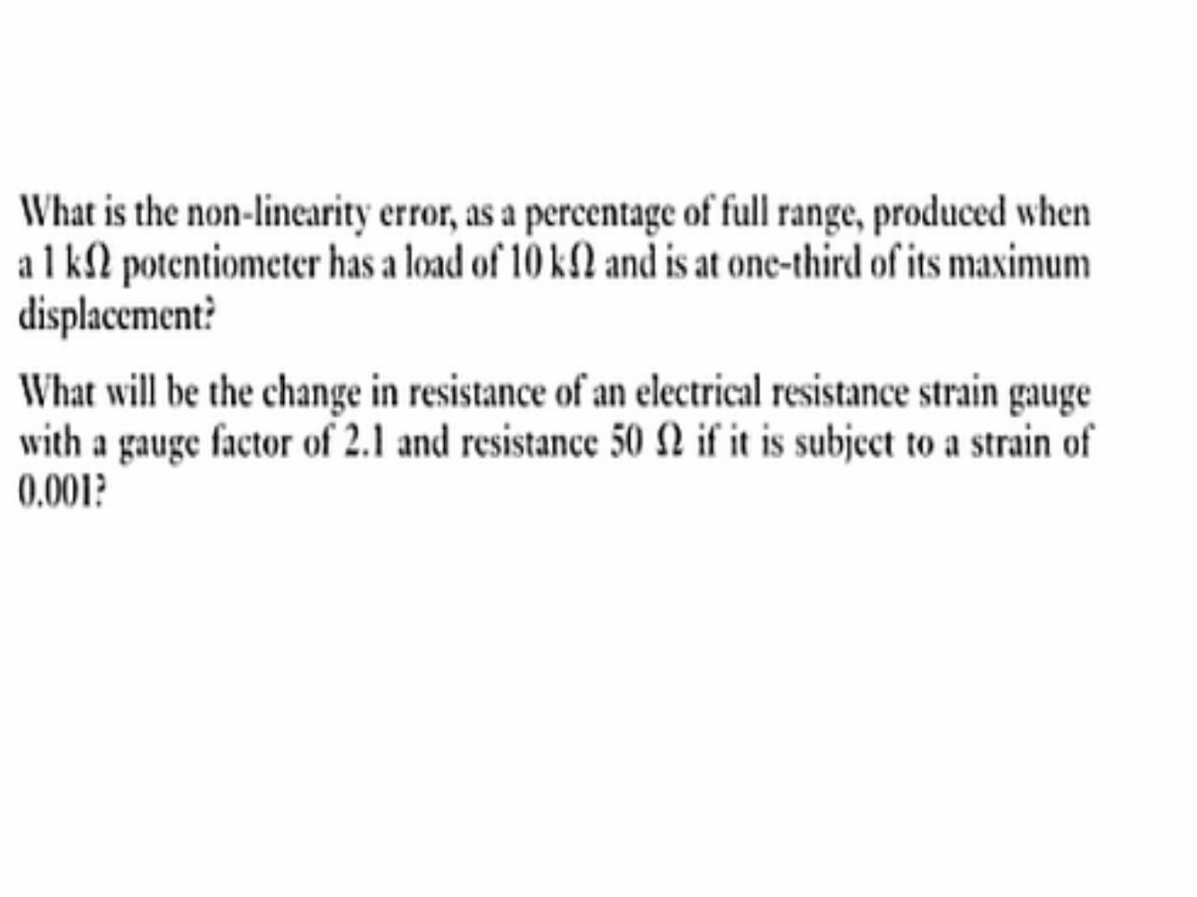
• A pontentiometer of resistance 500 ohms, when at a displacement of half its maximum slider travel, which results from there being a load of resistance 10Kohms. Its supply voltage is 4V. Find its non-linearity error.
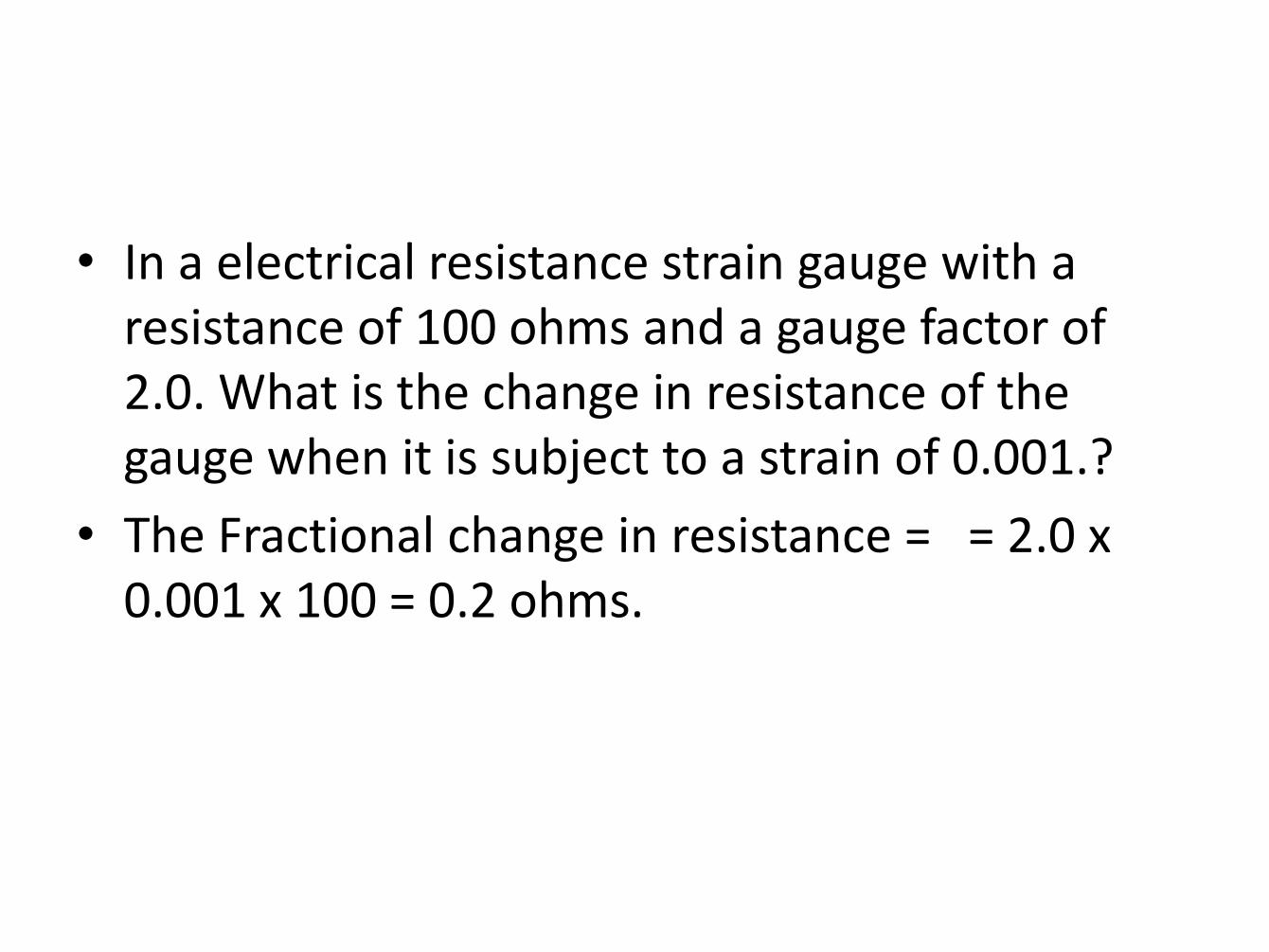
• In a electrical resistance strain gauge with a resistance of 100 ohms and a gauge factor of 2.0. What is the change in resistance of the gauge when it is subject to a strain of 0.001.?
• The Fractional change in resistance = = 2.0 x 0.001 x 100 = 0.2 ohms.
Capacitive Displacement Sensors
The capacitance of a parallel plate capacitor is
• d is the separation between the plates, A is the area of the plates, • ε0 is constant the permittivity of air and • εr is the relative permittivity of the dielectric distance between the plates • A moving object is attached to the dielectric or the plates to generate capacitance changes Notes • Variable distance (d) sensors operate over a range of a few millimeters • Cross-sensitivity to temperature and humidity (specially if the dielectric is air) • Capacitive sensors are also commonly used to measure pressure • “Condenser” microphones measure changes in air pressure of incoming sound waves

Capacitive Displacement Sensors

Capacitive Sensors
e.g. An electrolytic
capacitor is made of
Aluminum
evaporated on either
side of a very thin
plastic film (or
electrolyte)
Electrolytic or
ceramic capacitors
are most common

Capacitive Sensors Other Configurations
c. Differential Mode
b. Variable Dielectric Mode
a. Variable Area Mode
Push Pull Sensor
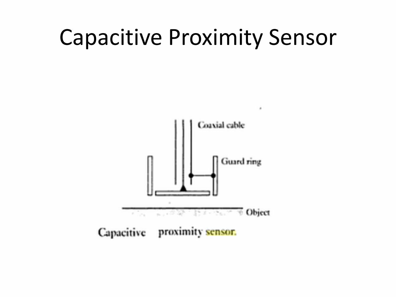
Capacitive Proximity Sensor
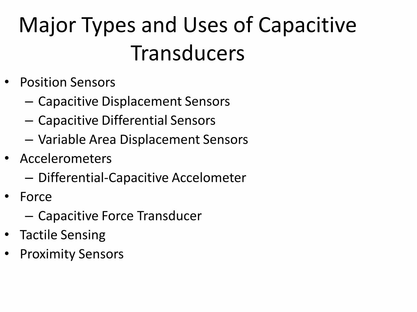
Major Types and Uses of Capacitive Transducers
• Position Sensors
– Capacitive Displacement Sensors
– Capacitive Differential Sensors
– Variable Area Displacement Sensors
• Accelerometers
– Differential-Capacitive Accelometer
• Force
– Capacitive Force Transducer
• Tactile Sensing
• Proximity Sensors

Common uses for Capacitive Transducers
• Measuring thicknesses with Capacitive Gauging • Most flow meters measure force. Capacitors are
common force sensors in these meters. • Liquid Level-Measures liquid levels by measuring
change in capacitance between two conductive plates • Measure consistencies based on variations of dielectric
between two conducting plates-In oil refineries capacitive sensors measure the % of water in oil
• Force Sensor Capacitors are used as pressure sensitive light dimming switches in many homes
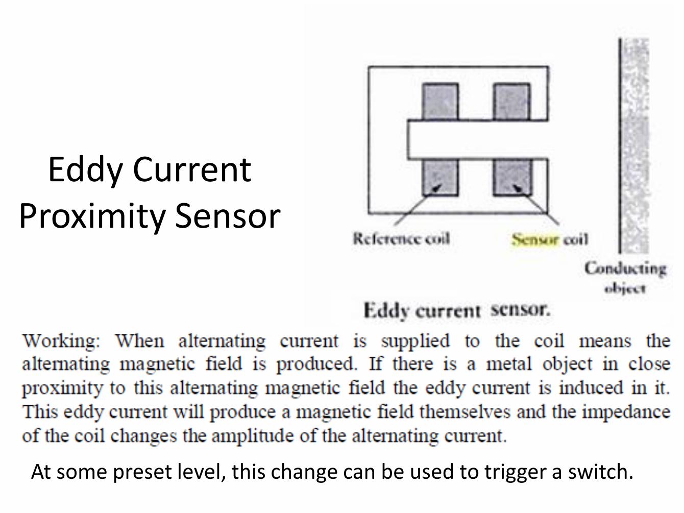
Eddy Current Proximity Sensor
At some preset level, this change can be used to trigger a switch.

Inductive Proximity Sensor
• The inductive proximity sensor can be used to detect metallic targets only.
• The main components of the inductive proximity sensor are coil, oscillator, detector and the output circuit.
• The coil generates the high frequency magnetic field in front of the face.
• When the metallic target comes in this magnetic field it absorbs some of the energy.
• Hence the oscillator field is affected. This is detected by the detector. if the oscillation amplitude reaches a certain threshold value the output switches.
• The inductive proximity sensor works better with ferromagnetic targets as they absorb more energy compare to non Ferromagnetic materials. Hence operating distance for sensor is more for Ferromagnetic targets.
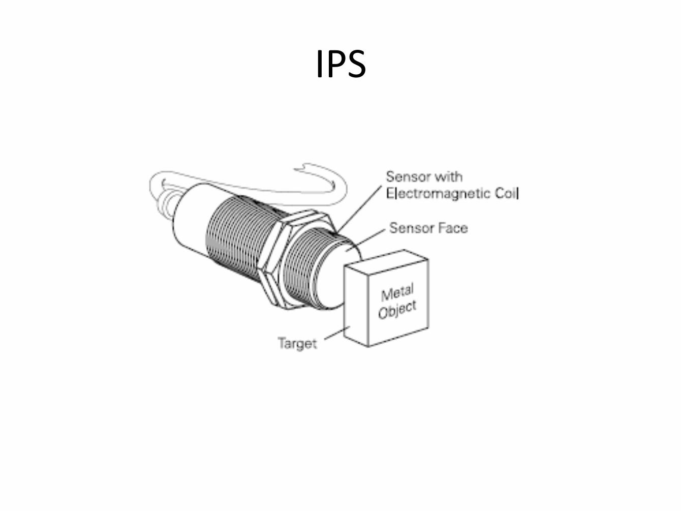
IPS
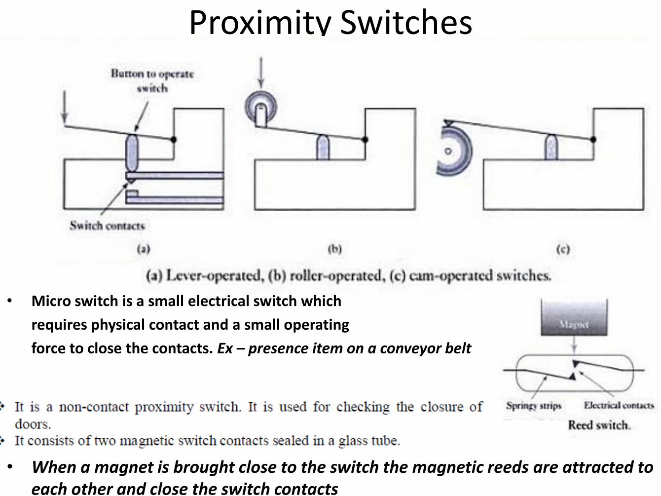
Proximity Switches
• Micro switch is a small electrical switch which
requires physical contact and a small operating
force to close the contacts. Ex – presence item on a conveyor belt
• When a magnet is brought close to the switch the magnetic reeds are attracted to each other and close the switch contacts
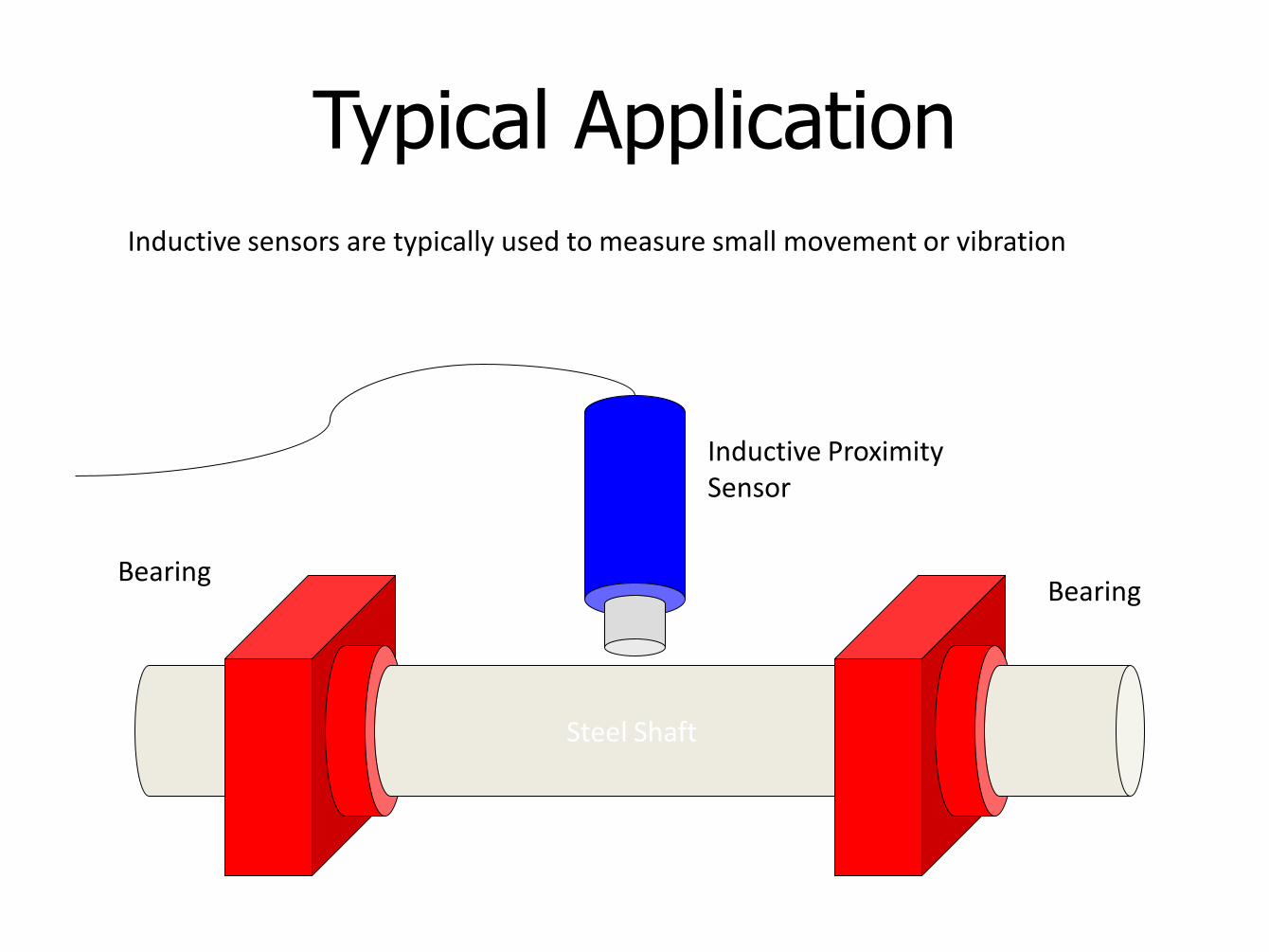
Typical Application
Steel Shaft
Bearing Bearing
Inductive Proximity Sensor
Inductive sensors are typically used to measure small movement or vibration
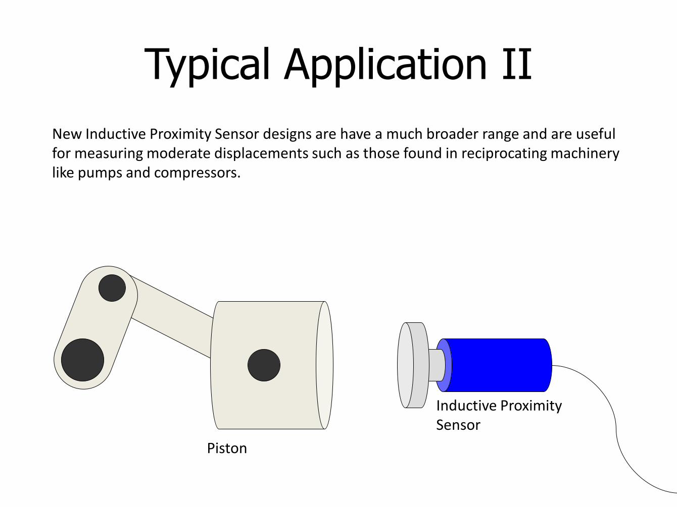
Typical Application II
New Inductive Proximity Sensor designs are have a much broader range and are useful for measuring moderate displacements such as those found in reciprocating machinery like pumps and compressors.
Piston
Inductive Proximity Sensor
Advantages of inductive proximity sensors
• They are very accurate compared to other technologies
• Have high switching rate
• Can work in harsh environmental conditions
The disadvantages of inductive proximity sensor are It can detect only metallic targets
• Operating range may be limited
• The Applications of Inductive proximity sensor are Proximity detection
Pneumatic Proximity Sensor
• Used to measure fractions of displacements of mm in ranges 3 to 12mm.

Photo Electric Sensors
Photo Sensitive Devices
• To detect the presence of an opaque object by its breaking a beam of light, or infrared radiation, falling on such a device or by detecting the light reflected back by the object.
Photo Electric Sensors
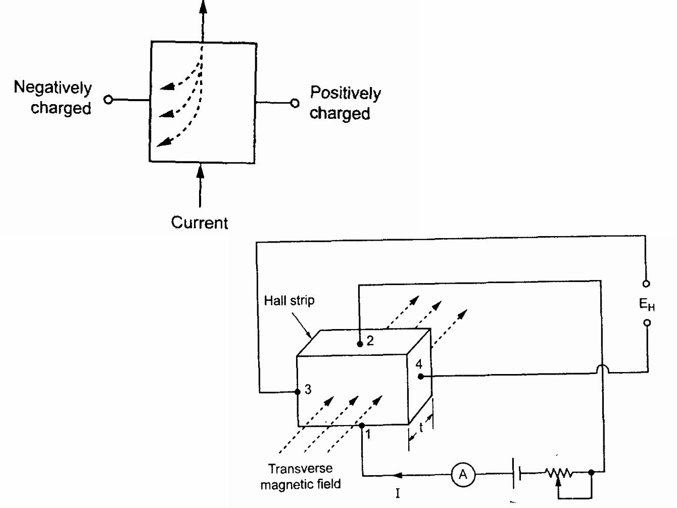
Hall Effect • When a beam of charged particles passes through a
magnetic field, forces act on the particles and the beam is deflected from its straight line path. A current flowing in a conductor is like a beam of moving charges and thus can be deflected by a magnetic field.
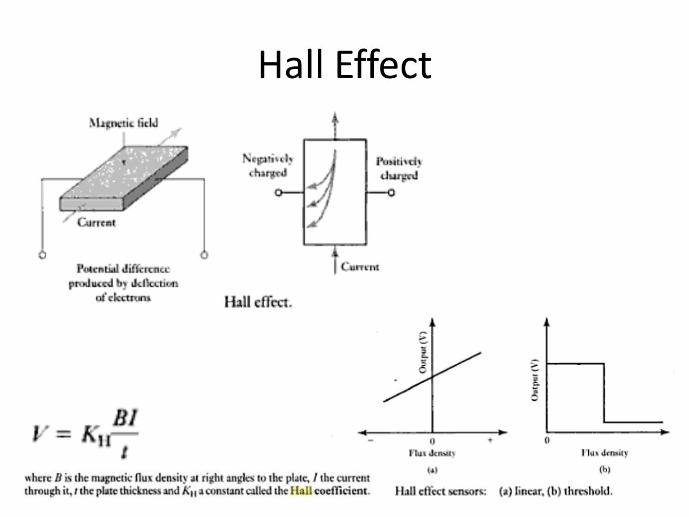
Hall Effect
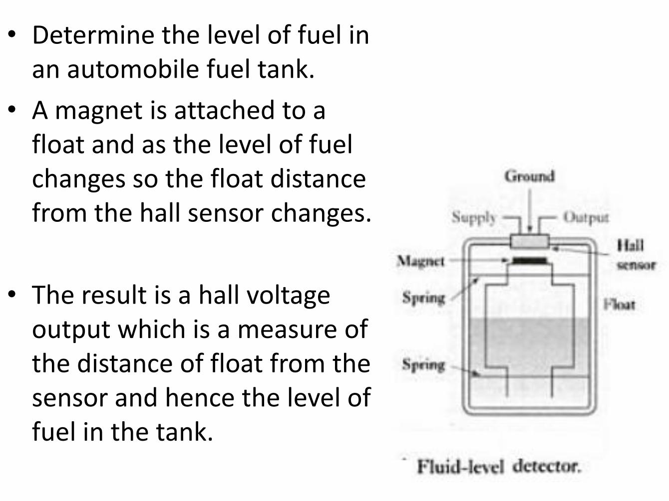
• Determine the level of fuel in an automobile fuel tank.
• A magnet is attached to a float and as the level of fuel changes so the float distance from the hall sensor changes.
• The result is a hall voltage output which is a measure of the distance of float from the sensor and hence the level of fuel in the tank.
Optical Encoder
• It is a device that provides a digital output as a result of a linear or angular displacement.
• Position encoders grouped into
– Incremental Encoder – detects changes in rotation from some datum position
– Absolute Encoder – gives the actual angular position.
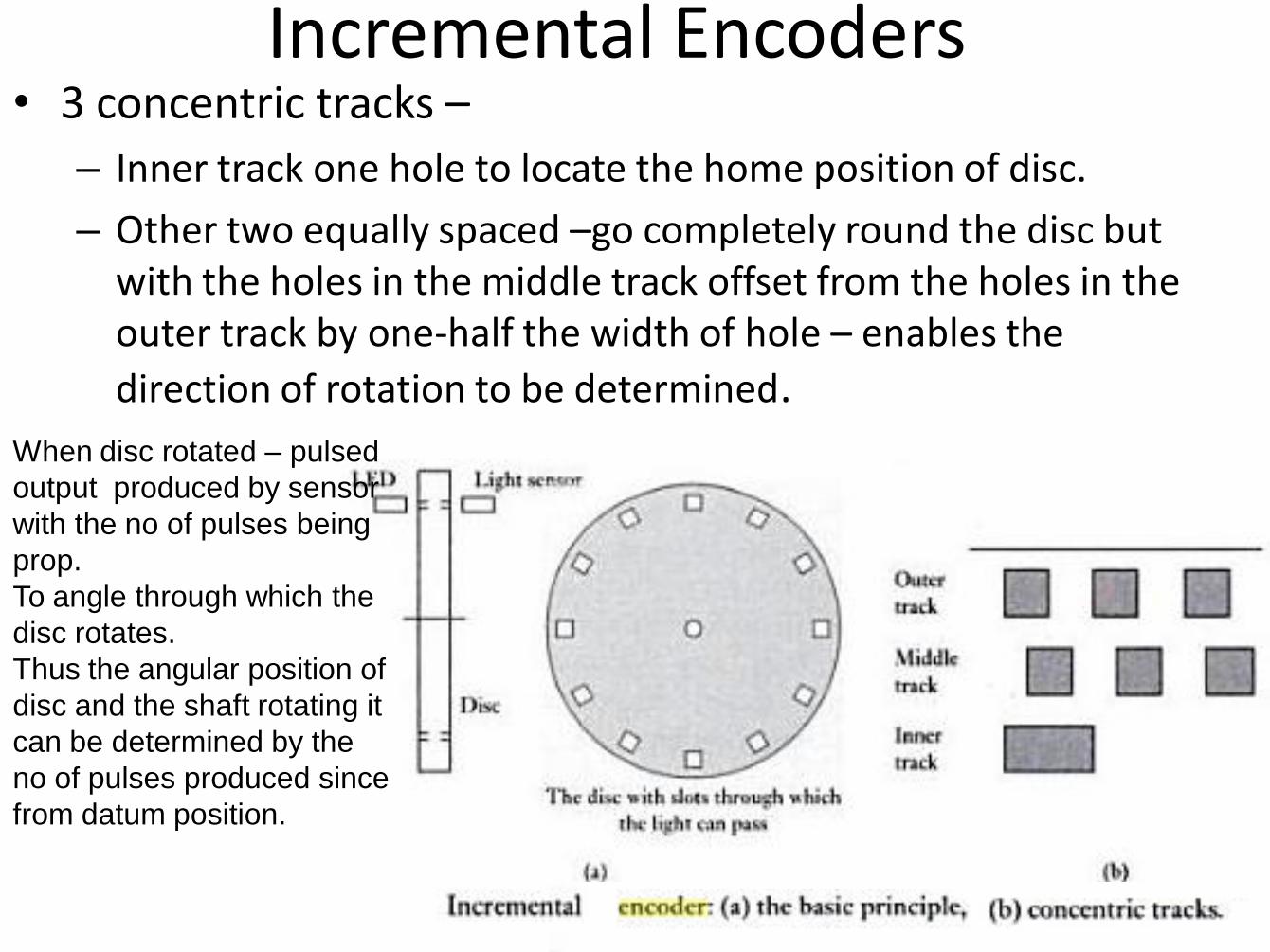
Incremental Encoders • 3 concentric tracks –
– Inner track one hole to locate the home position of disc.
– Other two equally spaced –go completely round the disc but with the holes in the middle track offset from the holes in the outer track by one-half the width of hole – enables the
direction of rotation to be determined.
When disc rotated – pulsed
output produced by sensor
with the no of pulses being
prop.
To angle through which the
disc rotates.
Thus the angular position of
disc and the shaft rotating it
can be determined by the
no of pulses produced since
from datum position.
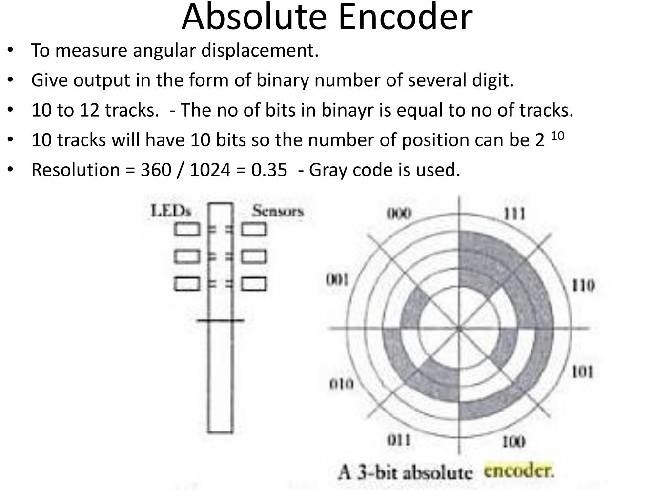
Absolute Encoder • To measure angular displacement.
• Give output in the form of binary number of several digit.
• 10 to 12 tracks. - The no of bits in binayr is equal to no of tracks.
• 10 tracks will have 10 bits so the number of position can be 2 10
• Resolution = 360 / 1024 = 0.35 - Gray code is used.
Velocity & Motion
• To detect the linear and angular velocity and motion.
• E.g Cash machine screen
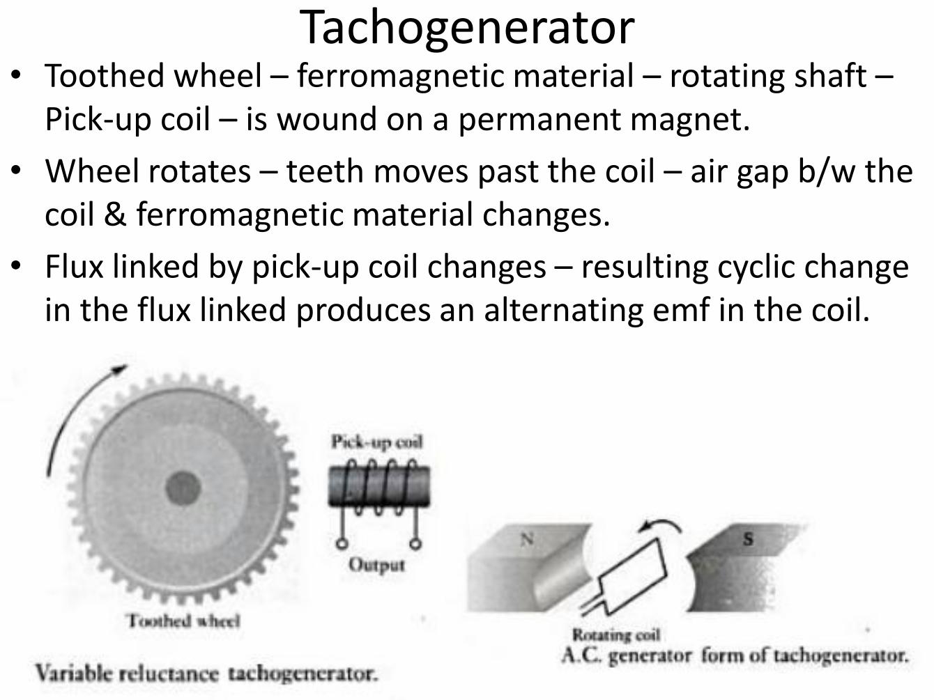
Tachogenerator • Toothed wheel – ferromagnetic material – rotating shaft –
Pick-up coil – is wound on a permanent magnet.
• Wheel rotates – teeth moves past the coil – air gap b/w the coil & ferromagnetic material changes.
• Flux linked by pick-up coil changes – resulting cyclic change in the flux linked produces an alternating emf in the coil.
Pyroelectric Sensor • Pyroelectric material – lithium tantalate – generates charge in
response to heat flow.
• Curie temp -610°C in electric field – cooled – electric dipoles within the material lineup – becomes polarised.
• Field removed , but retains its polarisation – i.e magnetising iron piece.
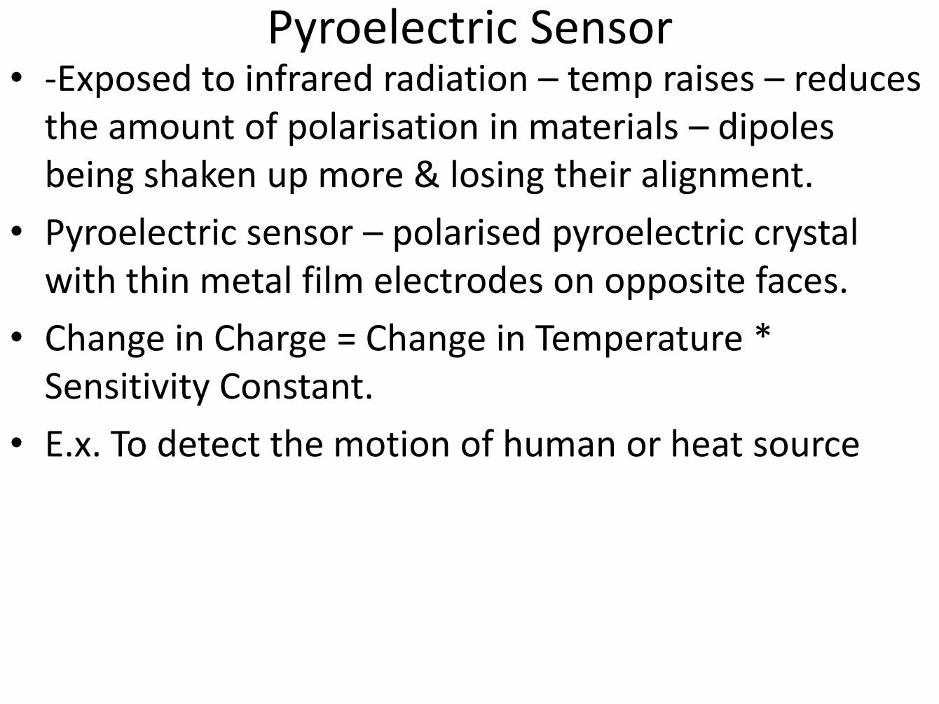
• -Exposed to infrared radiation – temp raises – reduces the amount of polarisation in materials – dipoles being shaken up more & losing their alignment.
• Pyroelectric sensor – polarised pyroelectric crystal with thin metal film electrodes on opposite faces.
• Change in Charge = Change in Temperature * Sensitivity Constant.
• E.x. To detect the motion of human or heat source
Pyroelectric Sensor
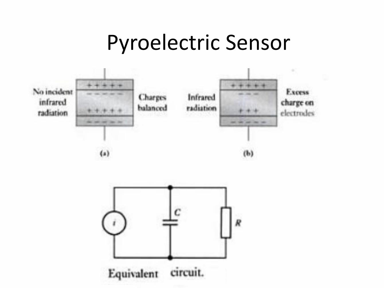
Pyroelectric Sensor
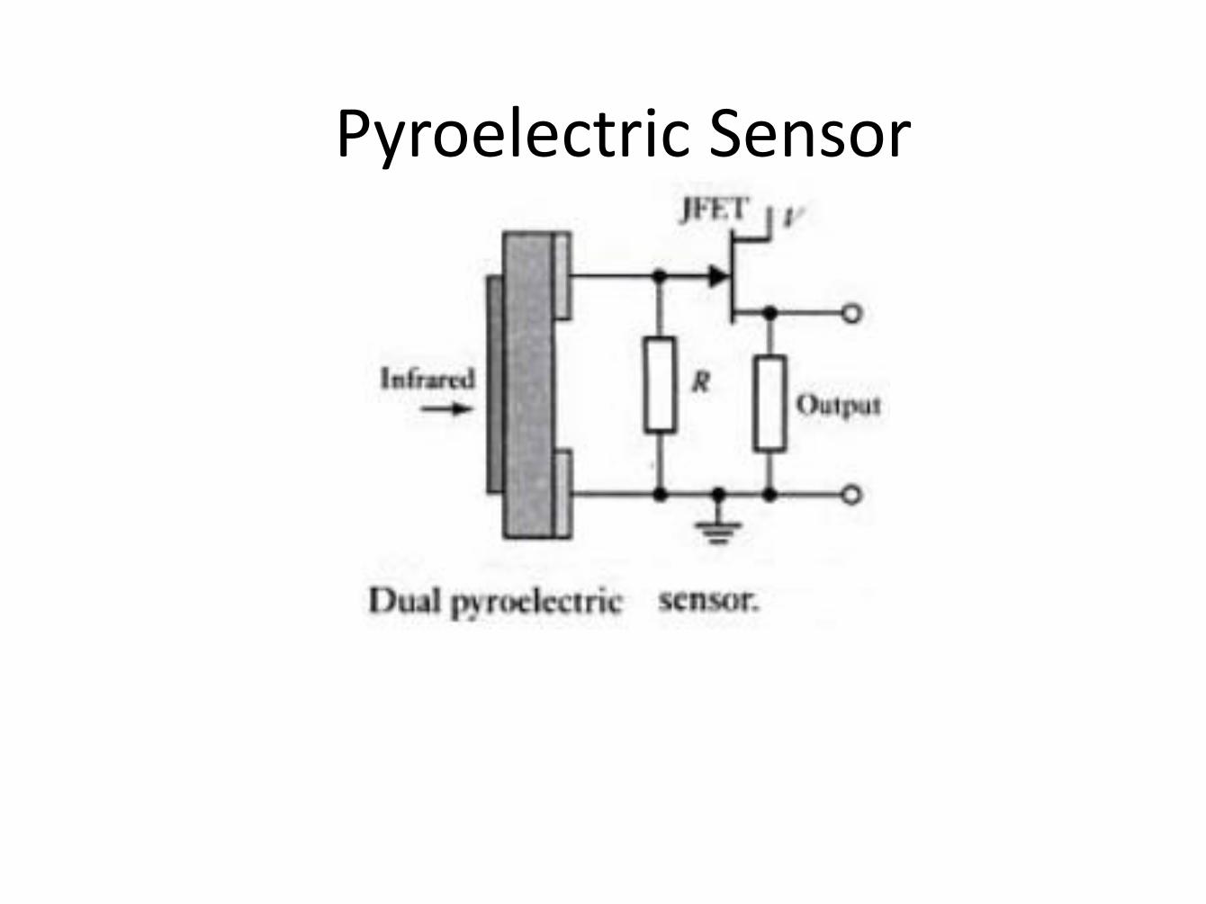
Pyroelectric Sensor

Force
Strain Gauge Load Cell
• Force Measuring transducer based on the use of electrical resistance strain gauges to monitor the strain produced in some member when stretched, compressed or bent by application of force.
• Max Force - 10MN
Fluid Pressure
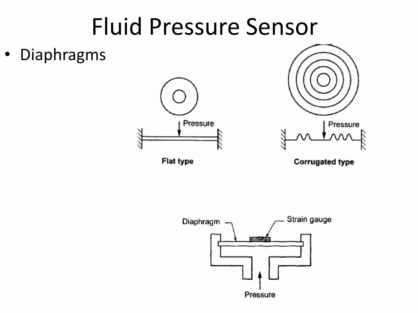
Fluid Pressure Sensor • Diaphragms
Fluid Pressure Sensor
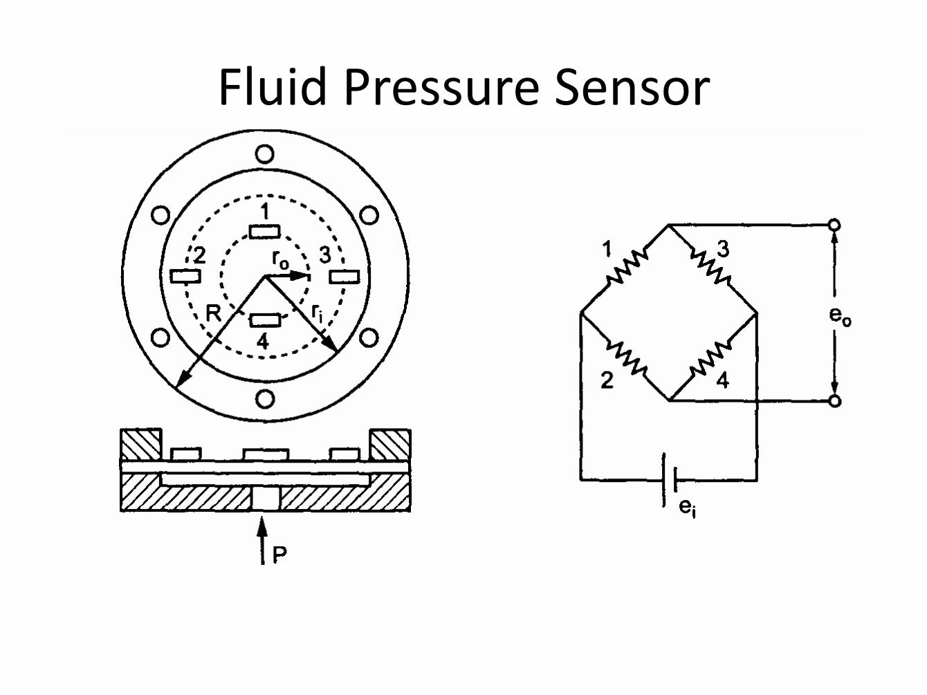
Fluid Pressure Sensor
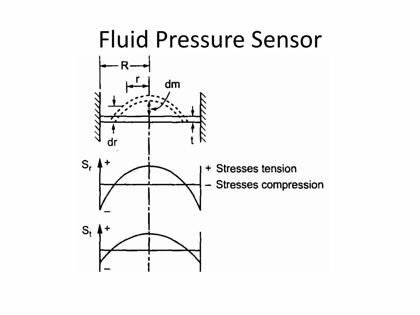
Fluid Pressure Sensor
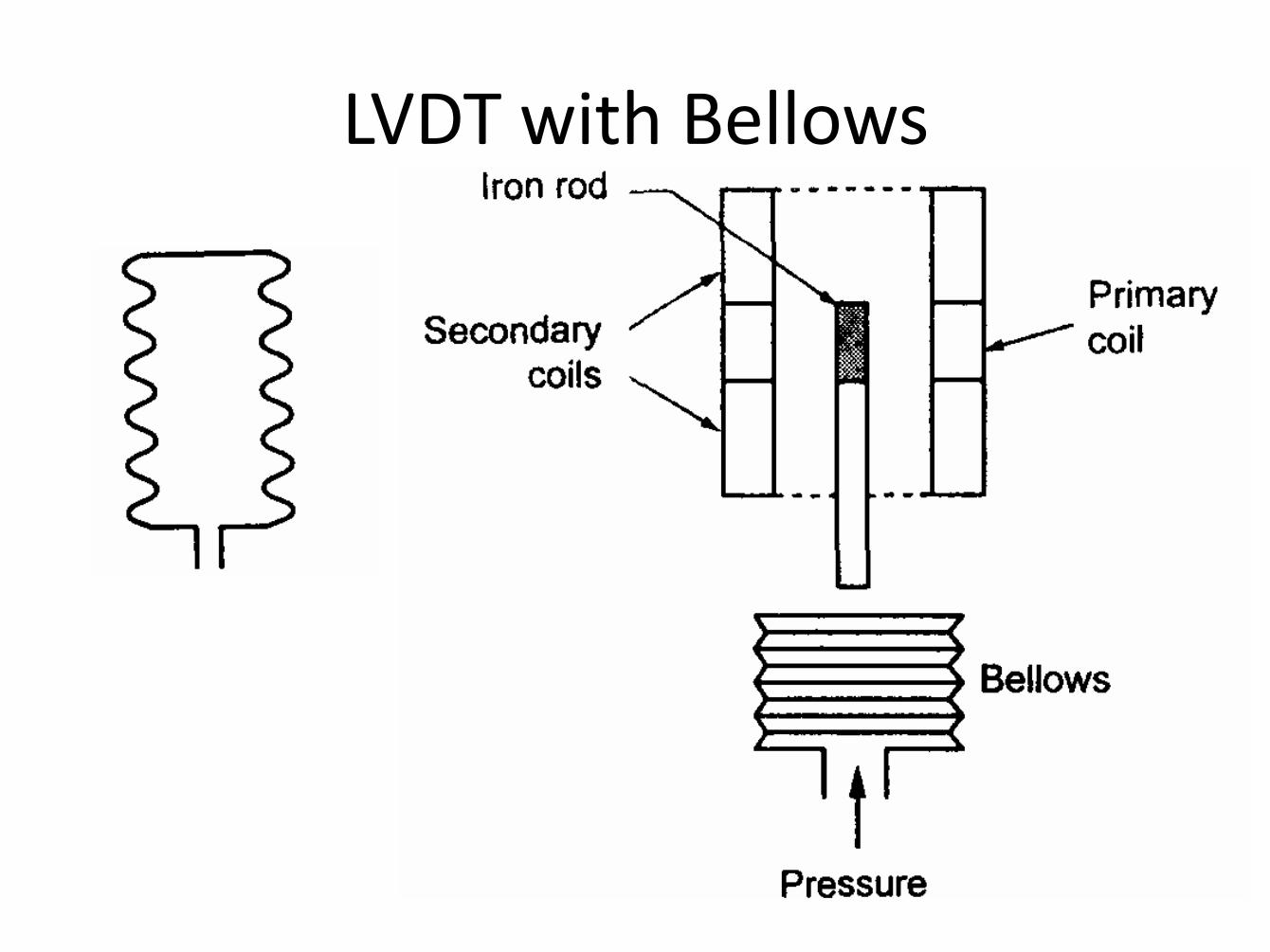
LVDT with Bellows
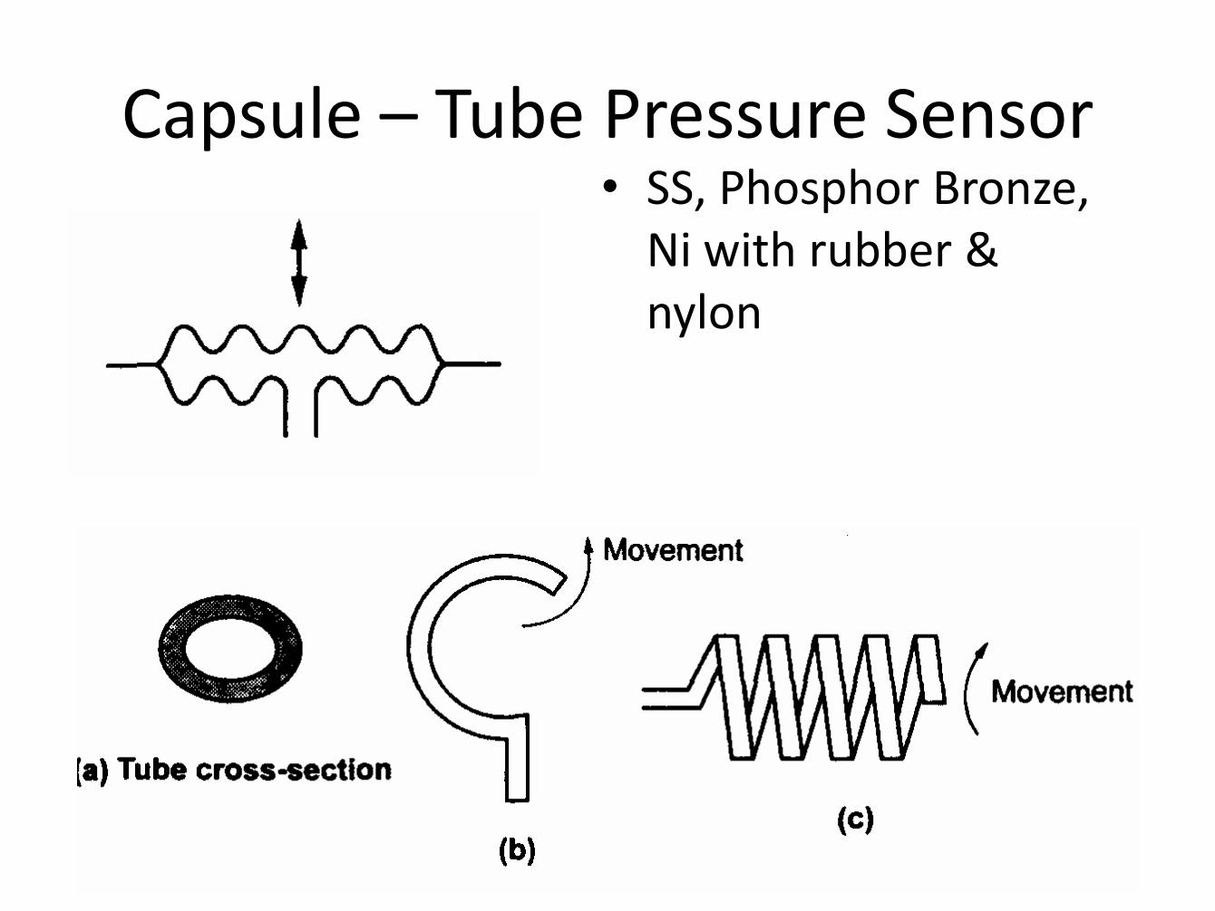
Capsule – Tube Pressure Sensor • SS, Phosphor Bronze,
Ni with rubber & nylon
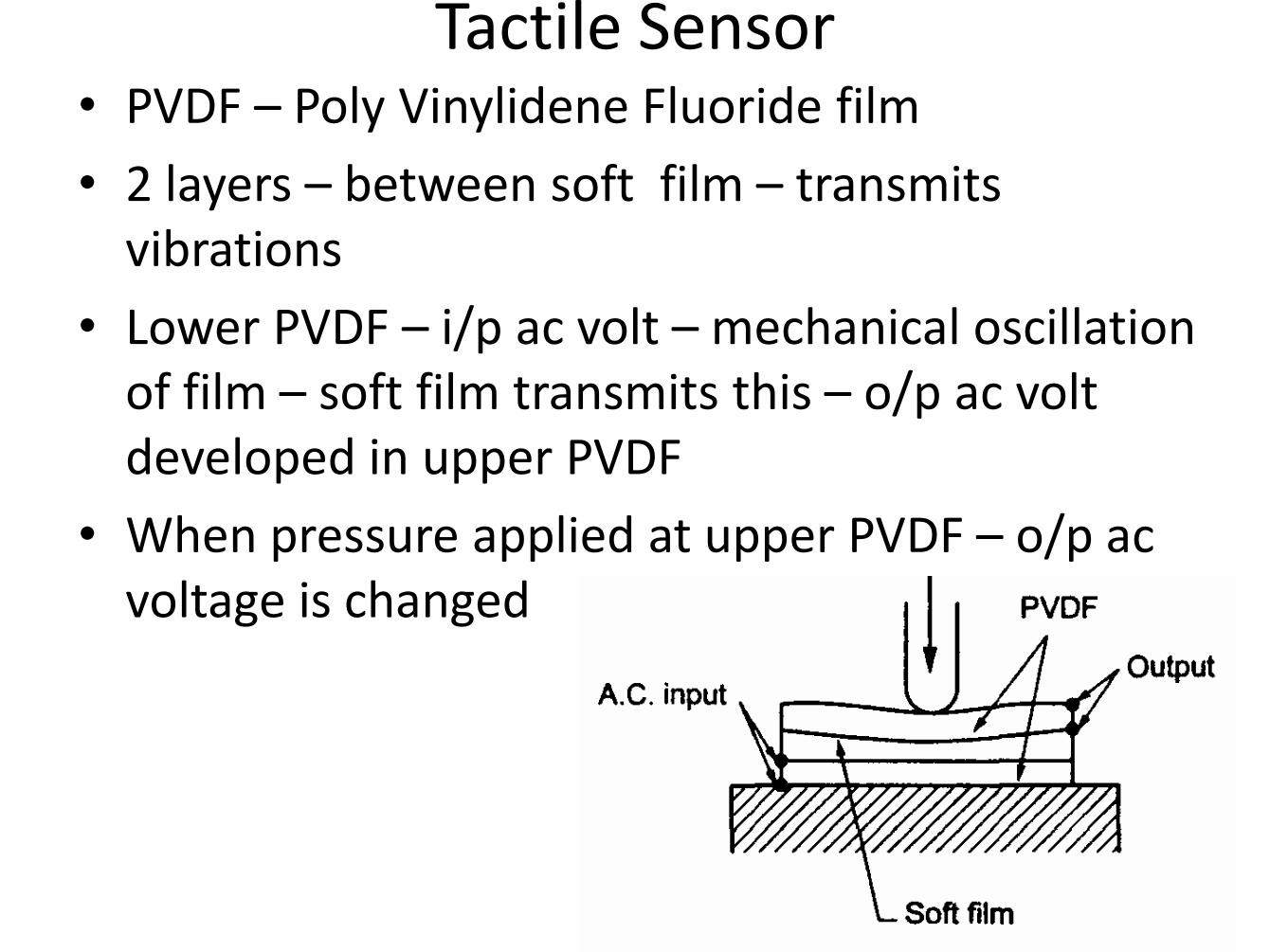
Tactile Sensor • PVDF – Poly Vinylidene Fluoride film
• 2 layers – between soft film – transmits vibrations
• Lower PVDF – i/p ac volt – mechanical oscillation of film – soft film transmits this – o/p ac volt developed in upper PVDF
• When pressure applied at upper PVDF – o/p ac voltage is changed
Piezoelectric Sensors – Pr, Force, Acceleration
What is piezoelectricity ?
Strain causes a
redistribution of charges
and results in a net
electric dipole (a dipole is
kind of a battery!)
A piezoelectric material
produces voltage by
distributing charge (under
mechanical strain/stress) –
generate electric charges
Different transducer applications:
Accelerometer
Microphone
Piezoelectric effect
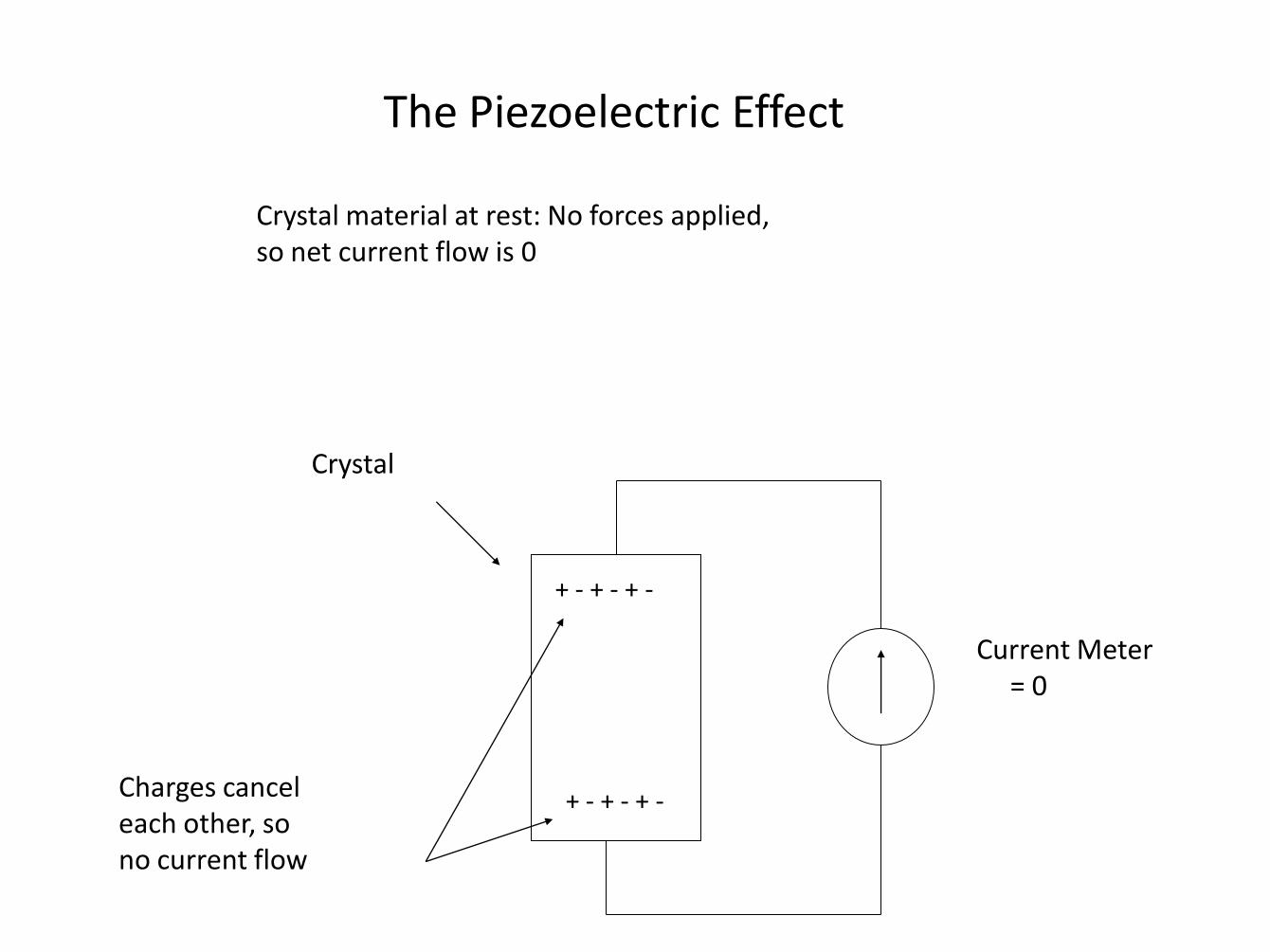
The Piezoelectric Effect
Crystal
Current Meter = 0
+ - + - + -
+ - + - + - Charges cancel each other, so no current flow
Crystal material at rest: No forces applied, so net current flow is 0
The Piezoelectric Effect
Crystal
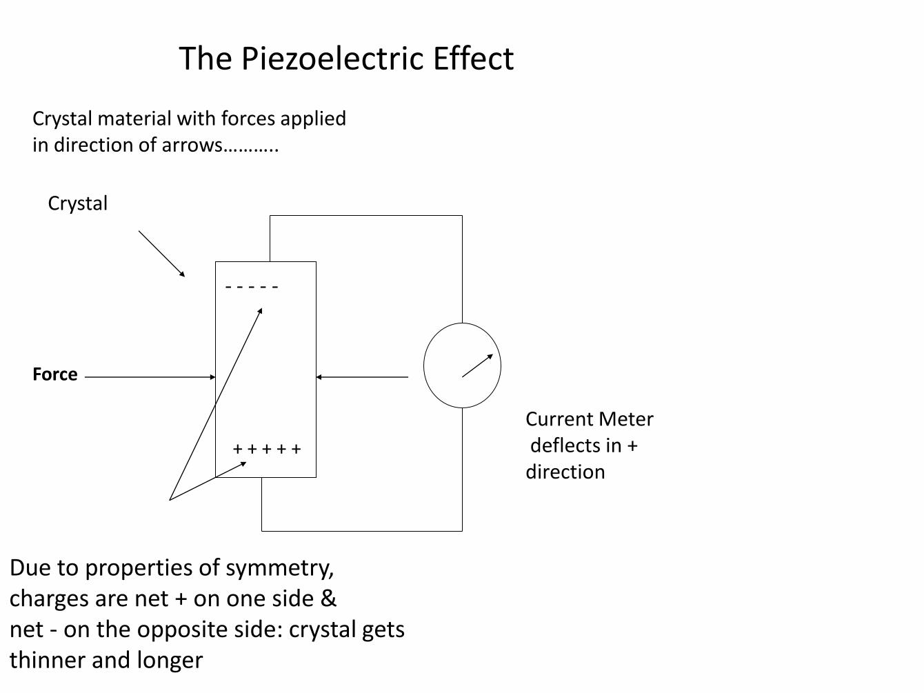
Current Meter deflects in + direction
- - - - -
+ + + + +
Due to properties of symmetry, charges are net + on one side & net - on the opposite side: crystal gets thinner and longer
Crystal material with forces applied in direction of arrows………..
Force
The Piezoelectric Effect
Crystal
Current Meter deflects in - direction
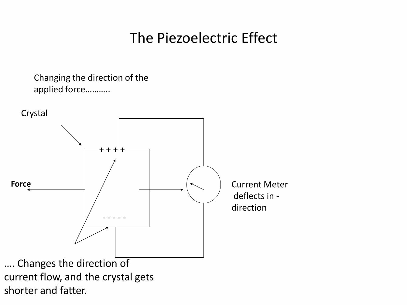
+ + + +
- - - - -
…. Changes the direction of current flow, and the crystal gets shorter and fatter.
Changing the direction of the applied force………..
Force
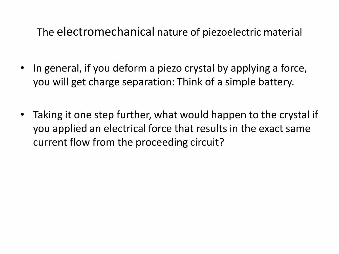
The electromechanical nature of piezoelectric material
• In general, if you deform a piezo crystal by applying a force, you will get charge separation: Think of a simple battery.
• Taking it one step further, what would happen to the crystal if you applied an electrical force that results in the exact same current flow from the proceeding circuit?
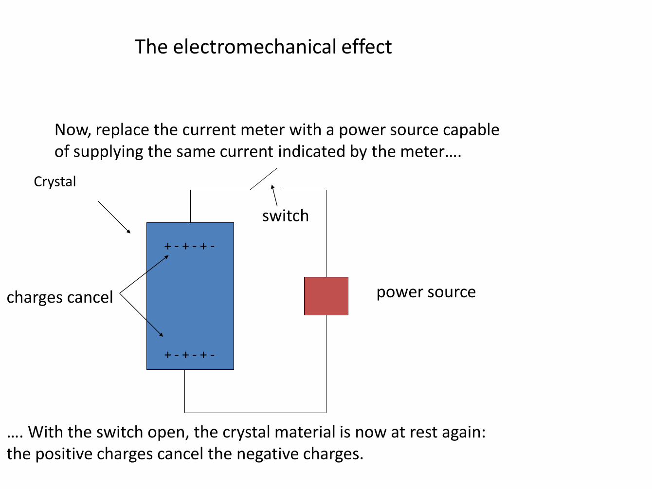
The electromechanical effect
Crystal
…. With the switch open, the crystal material is now at rest again: the positive charges cancel the negative charges.
Now, replace the current meter with a power source capable of supplying the same current indicated by the meter….
+ - + - + -
+ - + - + -
power source
switch
charges cancel
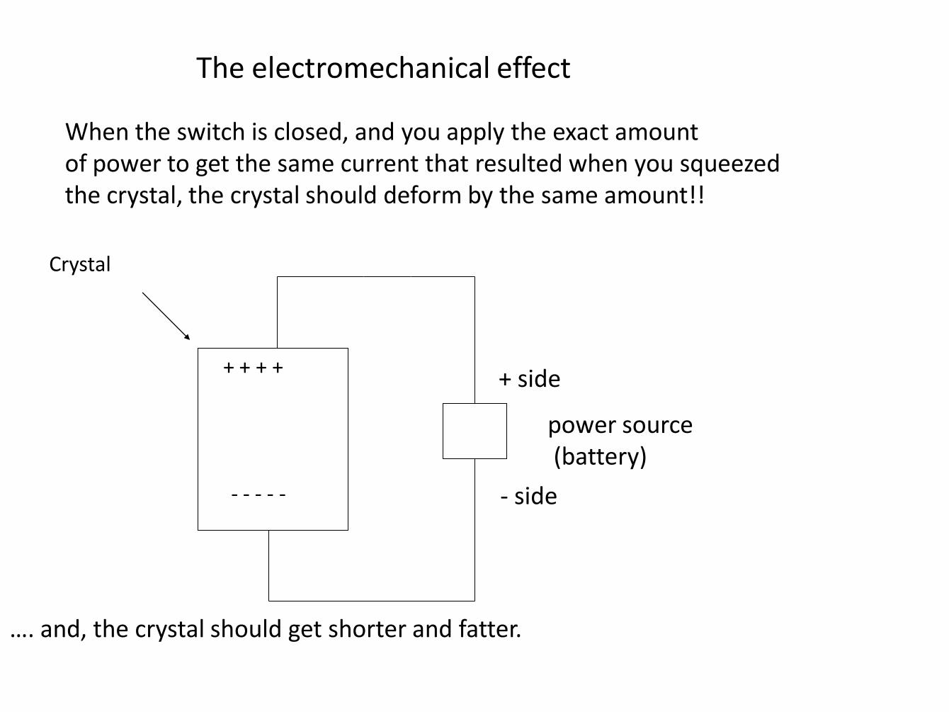
The electromechanical effect
Crystal
…. and, the crystal should get shorter and fatter.
When the switch is closed, and you apply the exact amount of power to get the same current that resulted when you squeezed the crystal, the crystal should deform by the same amount!!
power source (battery)
+ side
- side
+ + + +
- - - - -
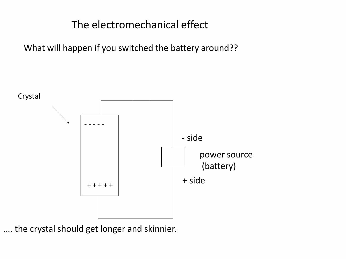
The electromechanical effect
Crystal
…. the crystal should get longer and skinnier.
What will happen if you switched the battery around??
power source (battery)
- side
+ side
- - - - -
+ + + + +
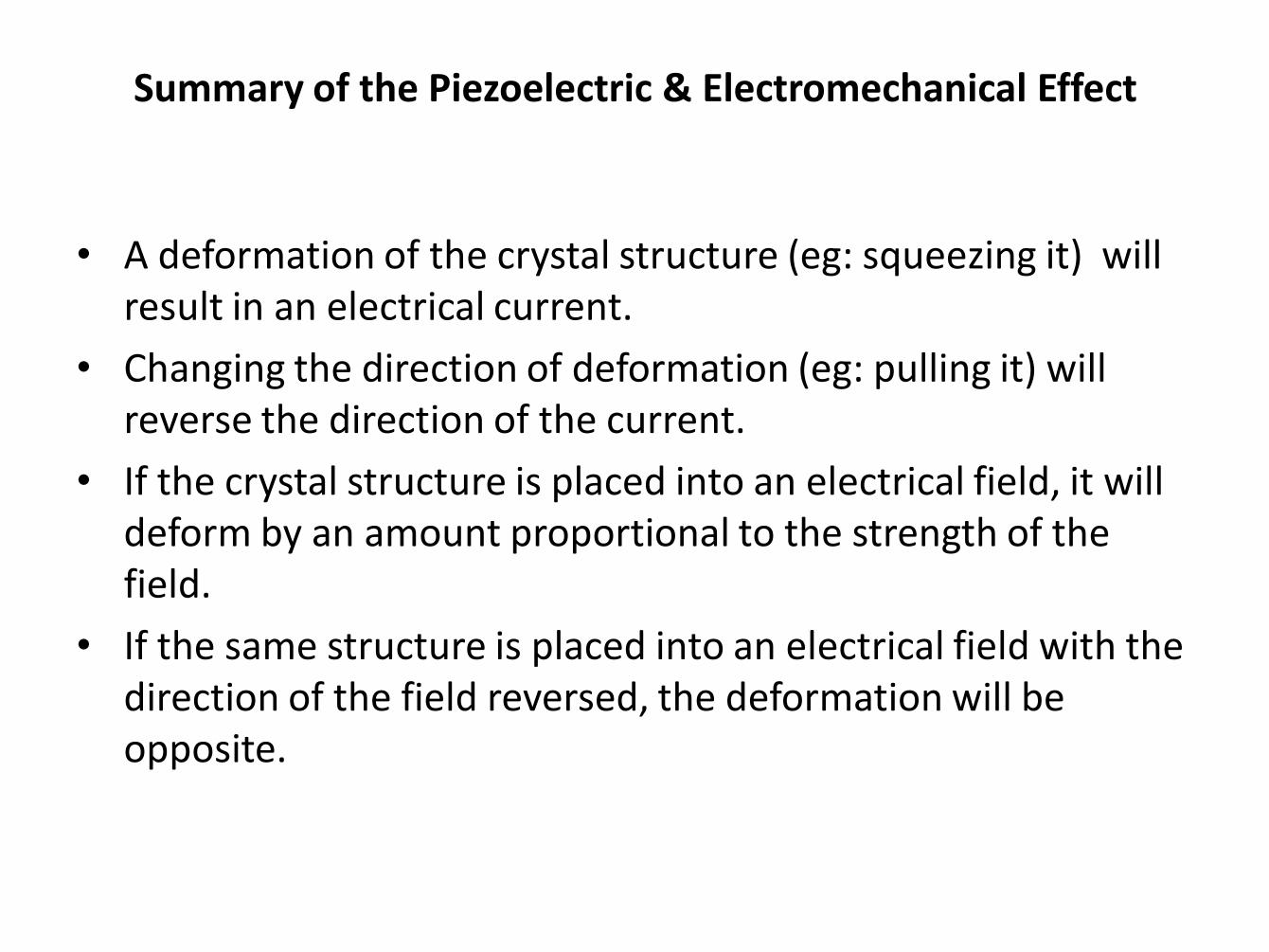
Summary of the Piezoelectric & Electromechanical Effect
• A deformation of the crystal structure (eg: squeezing it) will result in an electrical current.
• Changing the direction of deformation (eg: pulling it) will reverse the direction of the current.
• If the crystal structure is placed into an electrical field, it will deform by an amount proportional to the strength of the field.
• If the same structure is placed into an electrical field with the direction of the field reversed, the deformation will be opposite.
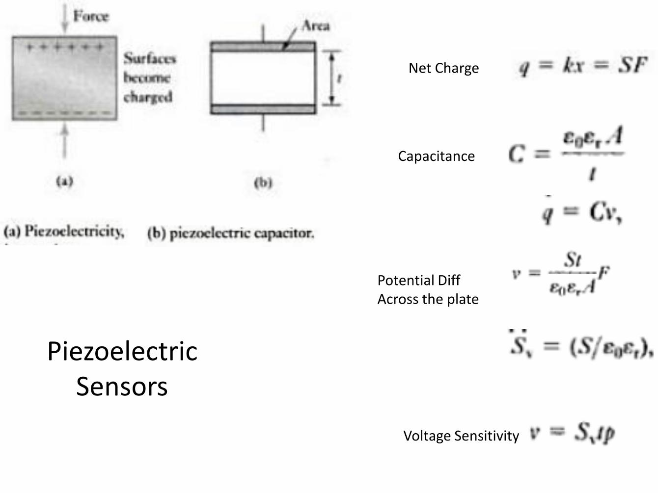
Net Charge
Capacitance
Potential Diff Across the plate
Voltage Sensitivity
Piezoelectric Sensors
Piezoelectric Sensors
Above equations are valid when force is applied in the L,W or t directions
respectively.
31 denotes
the crystal
axis
Piezoelectric Sensors - Circuitry
The Equivalent Circuit
Taken from Webster, “Medical Instrumentation”
Piezoelectric Sensor
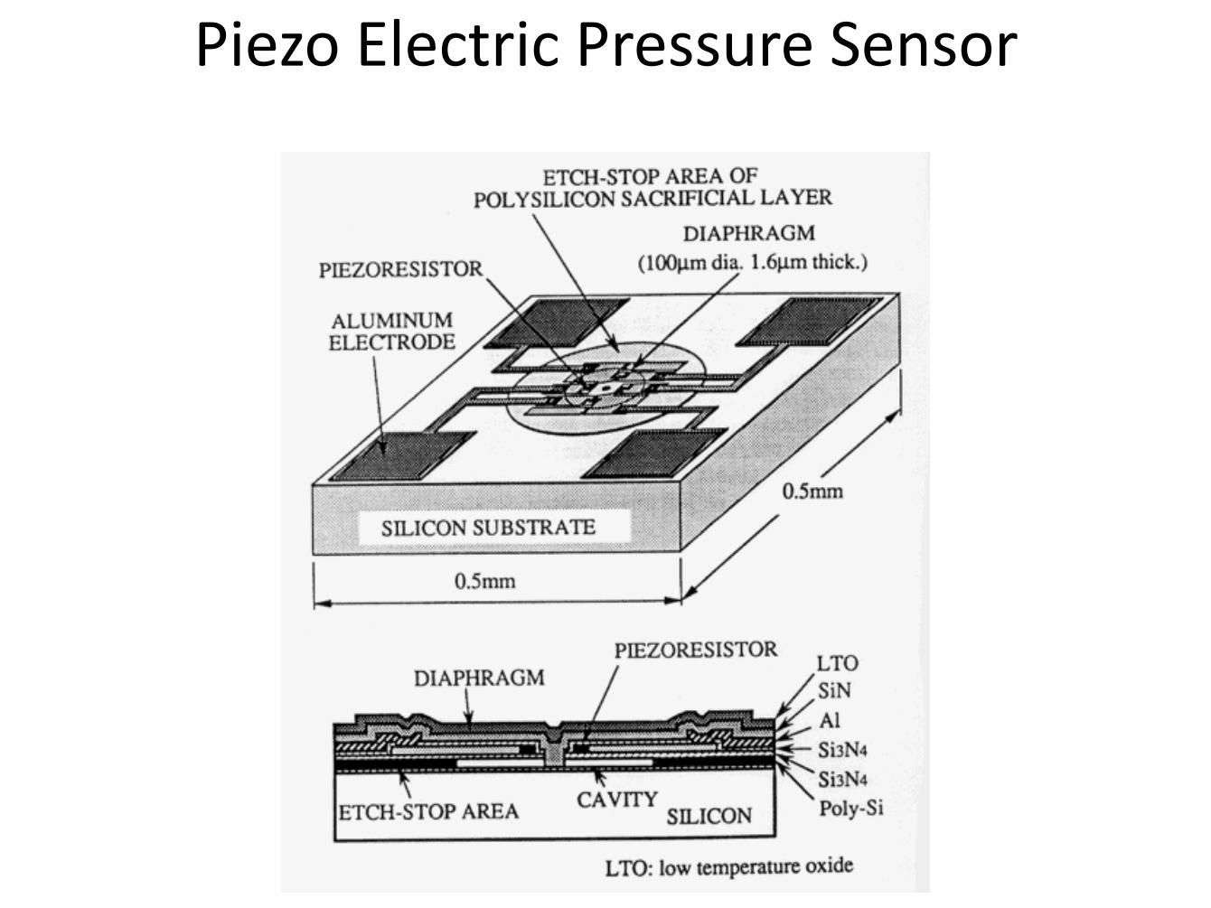
Piezo Electric Pressure Sensor
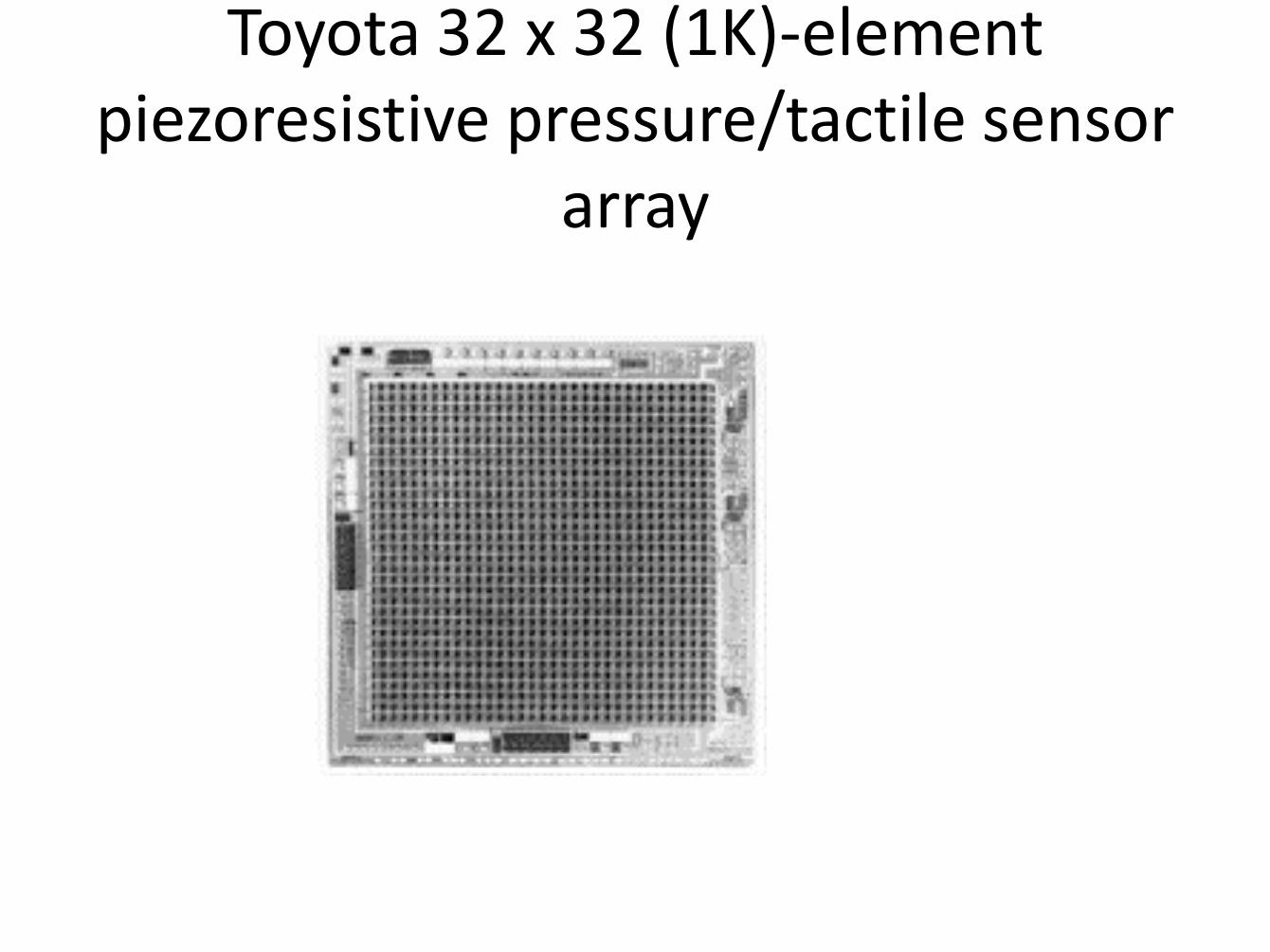
Toyota 32 x 32 (1K)-element piezoresistive pressure/tactile sensor
array

Sumo Bot

Thermal effects
• Temperature will change the resistance of the gage.
• Compensation approaches:
– Using dummy gages
– Using special, inherently temperature compensated gages
Temperature Sensors
1. Resistance based
a. Resistance Temperature Devices (RTDs)
b. Thermistors
2. Thermoelectric – Thermocouples
3. Radiation Thermometry
4. Fiber Optic Sensor

Bimetallic Strip

Temperature - Bimetallic strip
• Two or more layers of different coefficient of thermal expansion
• Used in standard thermostats in house industrial
• Delta = fn (T, A, B)

Thermocouple If two different metals are joined together, a potentiometer difference occurs across the junction.
The potential difference depends on the metals used and the temperature of the Junction.
When both junctions are at the same temperature, there is no net e.m.f.
But if there is a difference in temperature between the junction the e.m.f. will be produced.

Thermocouples
See beck Effect
When a pair of dissimilar metals are joined at one end, and there is a
temperature difference between the joined ends and the open ends,
thermal emf is generated, which can be measured in the open ends.
This forms the basis of thermocouples.


Thermistors
Thermistors are made from semiconductor
material.
Generally, they have a negative temperature
coefficient (NTC), that is NTC thermistors
are most commonly used.
Ro is the resistance at a reference
point (in the limit, absolute 0).

Thermistors Thermistor is a semiconductor device that has a negative temperature coefficient of resistance in contrast to positive coefficient displayed by most metals. Thermistors are small pieces of material made from mixtures of metal oxides, such as Iron, cobalt, chromium, Nickel, and Manganese. The shape of the materials is in terms of discs, beads and
Temperature - RTD – Electrical Resistance
Thermometer or Resistance Temperature Device (RTD)
• Metallic wire wound around a ceramic or glass
core and hermetically sealed
• R = Ro [ 1 + α (T – To)]
– Where Ro and To are the ref. resistance at To (often ice)
• dR/dT is the sensitivity = α Ro
• Platinum RTDs very stable, non-oxidizing, -220C to 750C
RTDs
RTDs are made of materials whose resistance changes in
accordance with temperature
Metals such as platinum, nickel and copper are commonly
used.
They exhibit a positive temperature coefficient.
A commercial ThermoWorks RTD probe

Resistance temperature detectors (RTDs) or resistance thermometers are basic instruments for measurement of resistance. The materials used for RTDs are Nickel, Iron, Platinum, Copper, Lead, Tungsten, Mercury, Manganin, Silver, etc. The resistance of most metals increases over a limited temperature range and the relationship between Resistance and Temperature is shown below. The Resistance temperature detectors are simple, and resistive elements in the form of coils of wire

Machine tool, RTD sensing example
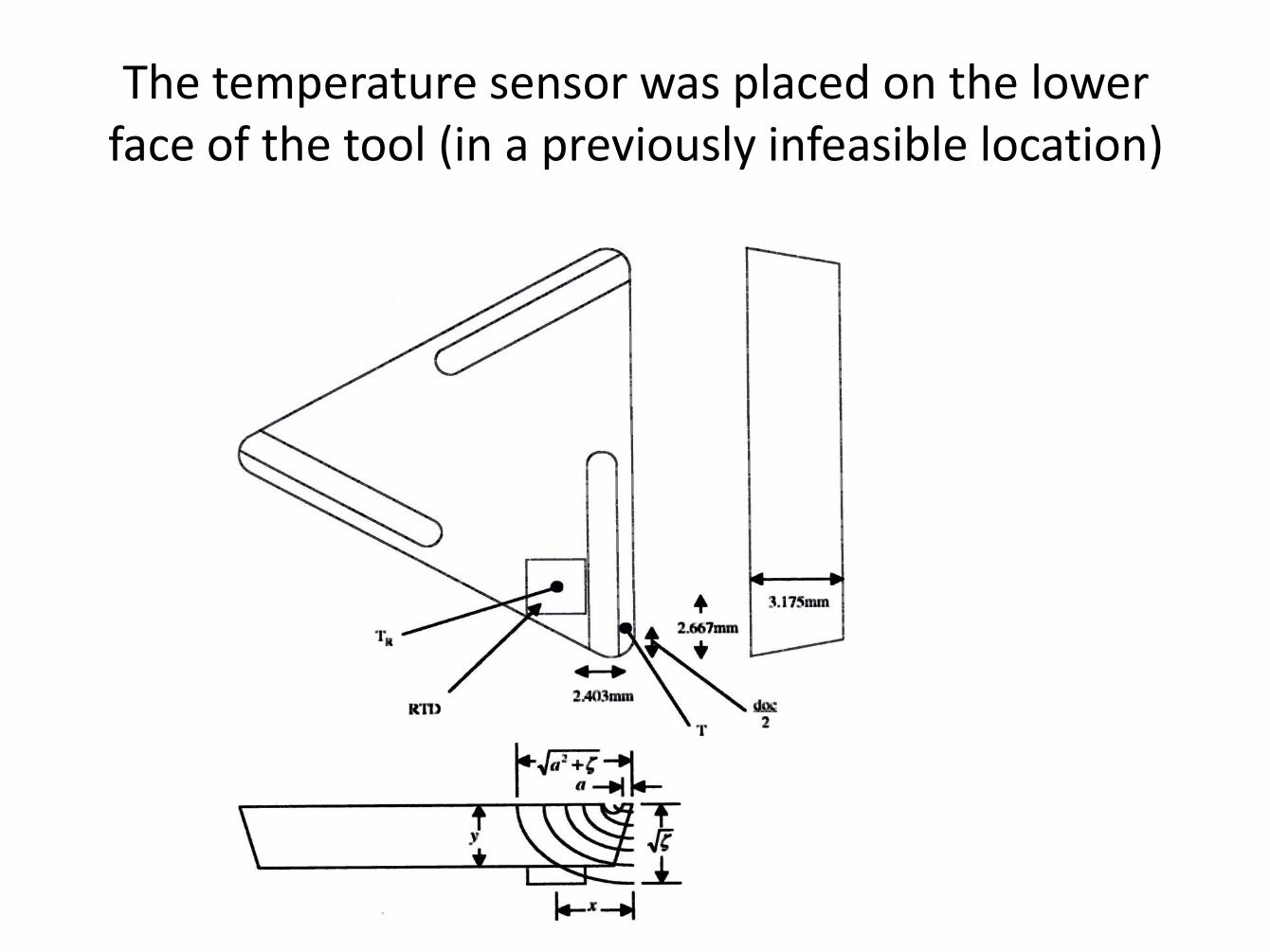
The temperature sensor was placed on the lower face of the tool (in a previously infeasible location)

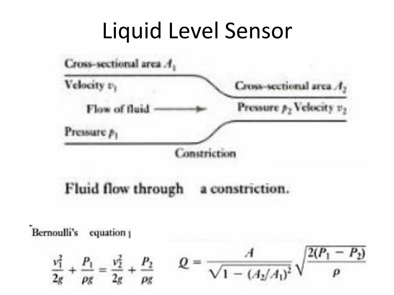
Liquid Level Sensor
Orifice Plate
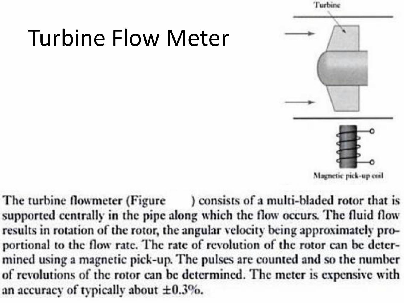
Turbine Flow Meter
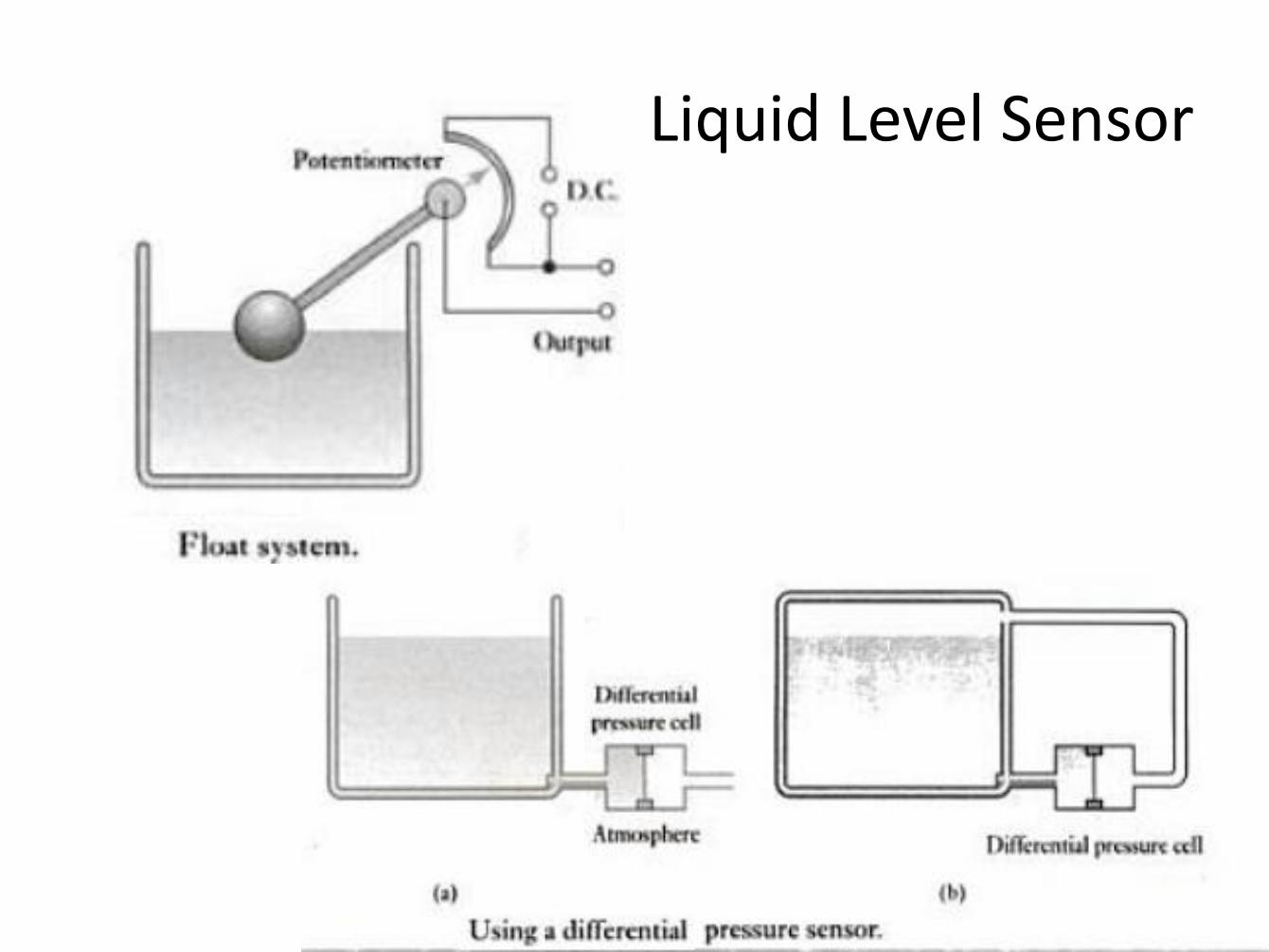
Liquid Level Sensor
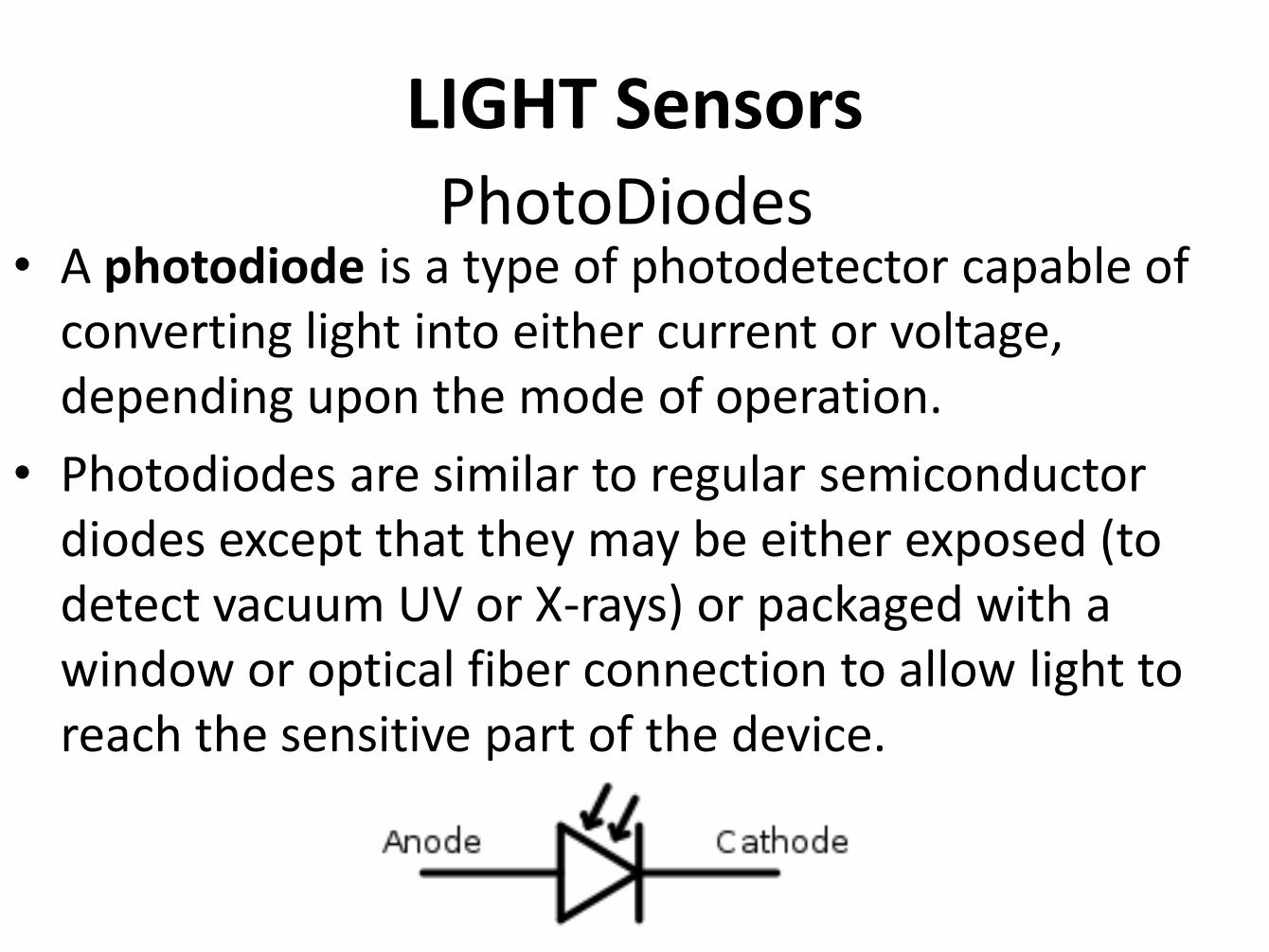
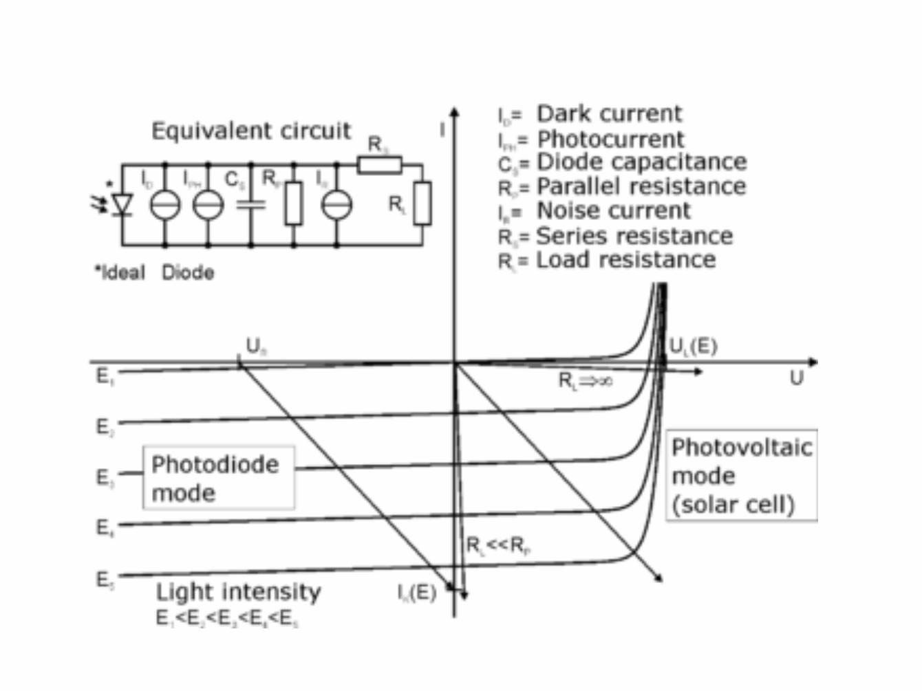
PhotoDiodes • A photodiode is a type of photodetector capable of
converting light into either current or voltage, depending upon the mode of operation.
• Photodiodes are similar to regular semiconductor diodes except that they may be either exposed (to detect vacuum UV or X-rays) or packaged with a window or optical fiber connection to allow light to reach the sensitive part of the device.
LIGHT Sensors
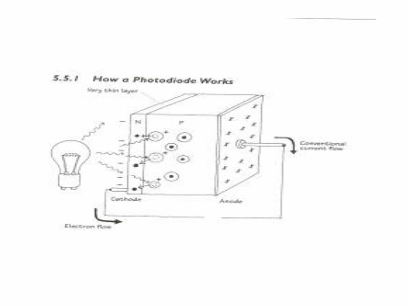
PhotoDiodes
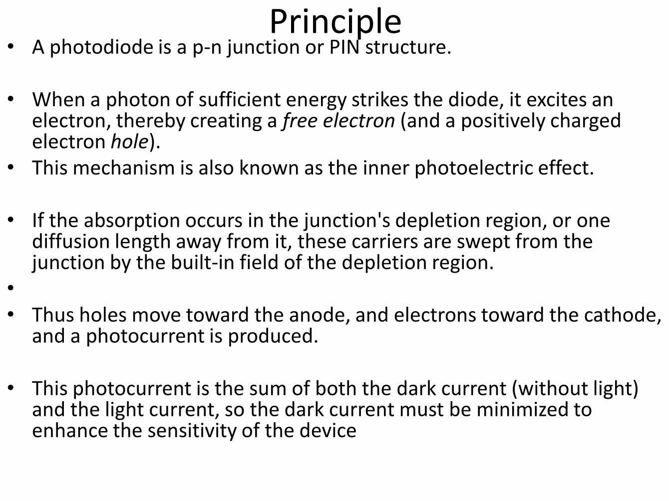
Principle • A photodiode is a p-n junction or PIN structure.
• When a photon of sufficient energy strikes the diode, it excites an
electron, thereby creating a free electron (and a positively charged electron hole).
• This mechanism is also known as the inner photoelectric effect.
• If the absorption occurs in the junction's depletion region, or one diffusion length away from it, these carriers are swept from the junction by the built-in field of the depletion region.
• • Thus holes move toward the anode, and electrons toward the cathode,
and a photocurrent is produced.
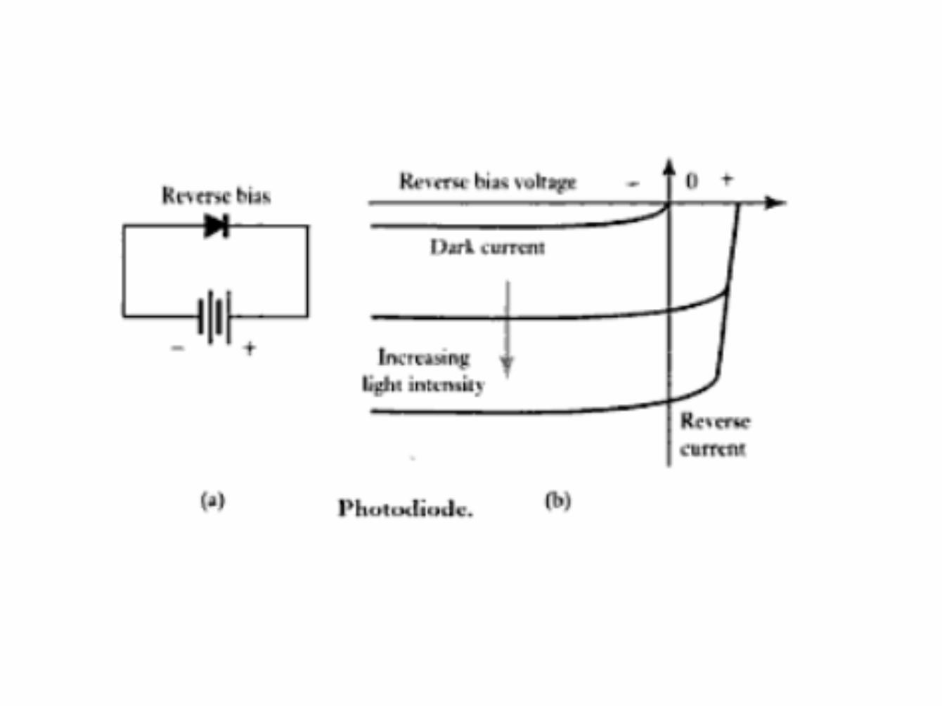
• This photocurrent is the sum of both the dark current (without light) and the light current, so the dark current must be minimized to enhance the sensitivity of the device
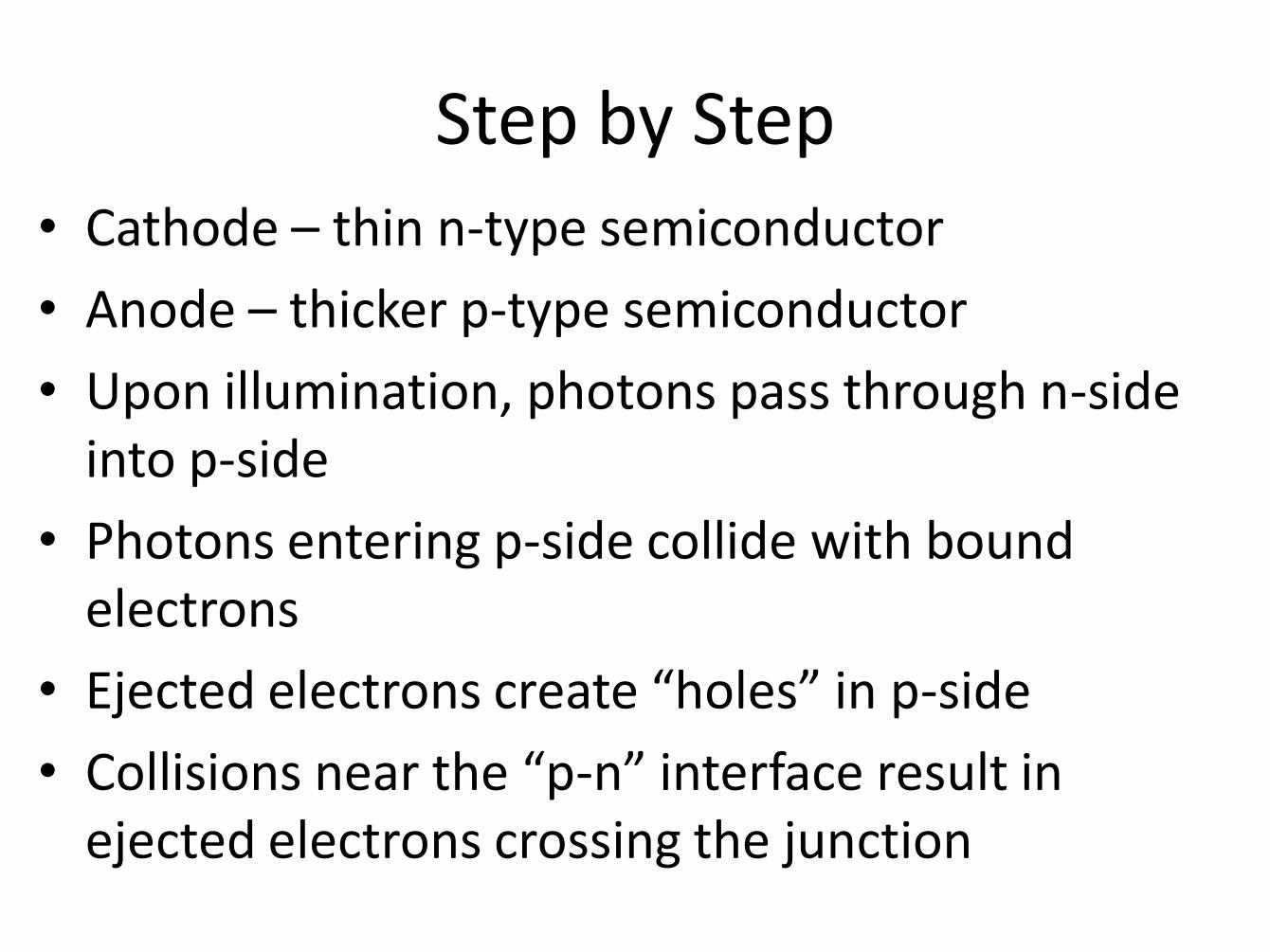
Step by Step
• Cathode – thin n-type semiconductor
• Anode – thicker p-type semiconductor
• Upon illumination, photons pass through n-side into p-side
• Photons entering p-side collide with bound electrons
• Ejected electrons create “holes” in p-side
• Collisions near the “p-n” interface result in ejected electrons crossing the junction
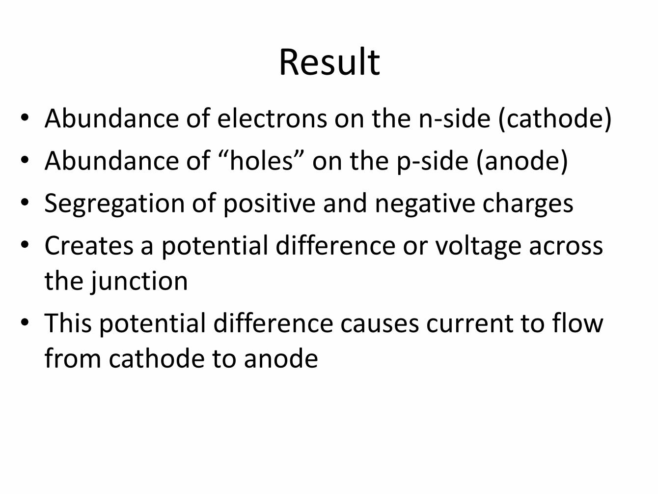
Result
• Abundance of electrons on the n-side (cathode)
• Abundance of “holes” on the p-side (anode)
• Segregation of positive and negative charges
• Creates a potential difference or voltage across the junction
• This potential difference causes current to flow from cathode to anode
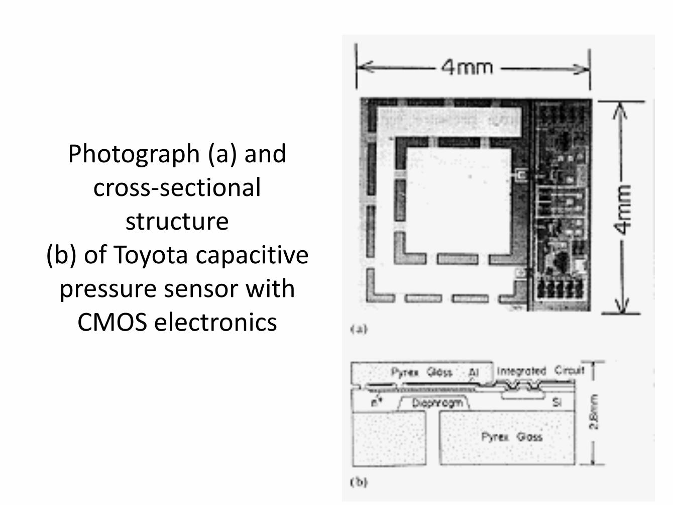
Photograph (a) and cross-sectional
structure (b) of Toyota capacitive
pressure sensor with CMOS electronics
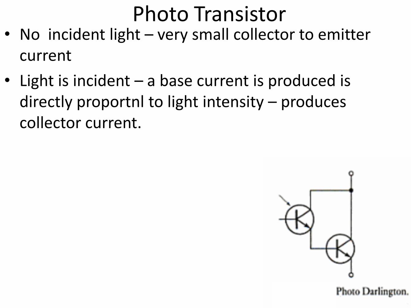
• No incident light – very small collector to emitter current
• Light is incident – a base current is produced is directly proportnl to light intensity – produces collector current.
Photo Transistor
Photo Transistor
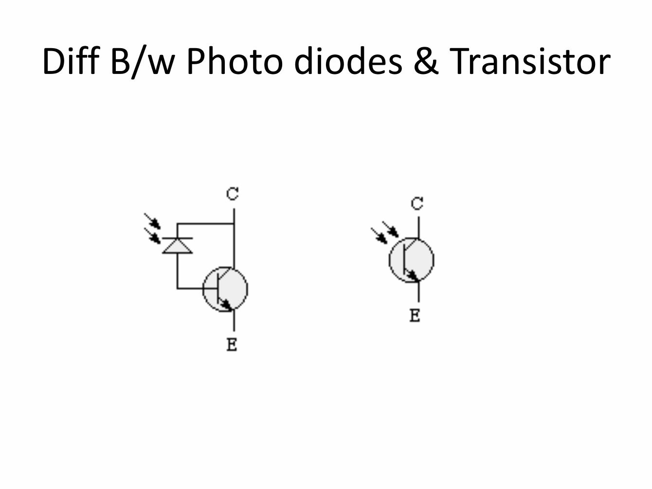
Diff B/w Photo diodes & Transistor
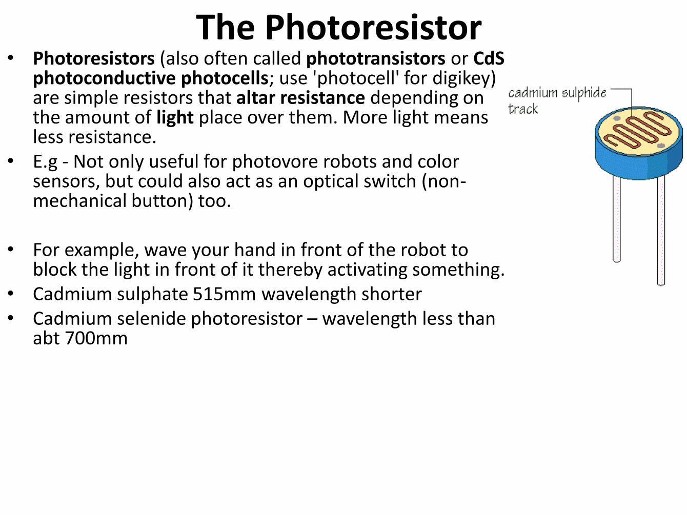
The Photoresistor • Photoresistors (also often called phototransistors or CdS
photoconductive photocells; use 'photocell' for digikey) are simple resistors that altar resistance depending on the amount of light place over them. More light means less resistance.
• E.g - Not only useful for photovore robots and color sensors, but could also act as an optical switch (non-mechanical button) too.
• For example, wave your hand in front of the robot to block the light in front of it thereby activating something.
• Cadmium sulphate 515mm wavelength shorter • Cadmium selenide photoresistor – wavelength less than
abt 700mm
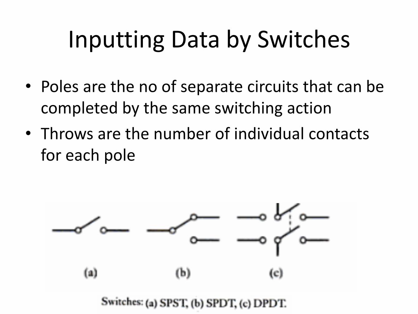
Inputting Data by Switches
• Poles are the no of separate circuits that can be completed by the same switching action
• Throws are the number of individual contacts for each pole
Selection of Sensor • The nature of the measurement required e.g. the
variable to be measured, its nominal value, the range of values, the accuracy required, the required speed of measurement, the reliability required, the environmental conditions under which the measurement is to be made.
• The nature of output required from the sensor, this determining the signal conditioning requirements in order to give suitable outputs signals from the measurements.
• Factors like range, accuracy, linearity, speed of response, reliability, maintainability, life, power supply requirements, ruggedness, availability and cost.