Embed Size (px)
Citation preview
International Journal of Computer Networks & Communications (IJCNC) Vol.9, No.1, January 2017
DOI: 10.5121/ijcnc.2017.9105 55
POSITION BASED ADAPTIVE ROUTING FOR
VANETS
Ajay Guleria1 and Kuldeep Singh
2
1Computer Centre, Panjab University, Chandigarh, India
2Computer Science & Application Department, Panjab University, Chandigarh, India
ABSTRACT
Routing plays a very significant role in multi hop data dissemination in Vehicular Ad-Hoc Networks
(VANETs). Wehave proposed a Position based Adaptive Routing (PAR) protocol which is scalable for dif-
ferent network densities in VANETs. This scheme uses Preferred Group Broadcasting (PGB) for route dis-
covery. In this mode, after broadcasting the request for route discovery the source node starts listening to
the channel. If the packet is not further rebroadcasted by any neighbor in a set timeout, then it repeats the
broadcast. This process is repeated until the request reaches the destination. The destination keeps on ac-
cumulating route requests coming from different paths until predefined time. It then chooses the least cost
path as route reply. It uses the set of traversed anchors for sending the unicast route reply to the source
node. PAR uses Advance Greedy Forwarding (AGF) for data forwarding and greedily forwards the data
packet to the next anchor towards destination node. It switches to carry and forward mode once it finds
partitions in the network. The intermediate vehicle buffers the packet until next junction and switches back
to position based scheme and greedily forwards to next node in range which is closest to the destination. To
have an end to end connectedpath, it uses guards to guard anchors tied to different junction and geo-
graphical locations in the network. The algorithm is scalable and exploits advantages of existing tech-
niques already developed for specific scenarios in VANET. Results show that the service ratio and packet
delay of PAR are higher than its counterparts.
KEYWORDS
PAR, PGB, AGF
1. INTRODUCTION
The coverage of road side unit (RSU) is limited by its radio range, so vehicles entering in its
range only can seek or upload data. The data disseminated by road side unit may be beneficial to
the other vehicles driving miles away. People driving in a specific area may be interested to re-
serve a parking place, book an accommodation, finding out petrol prices, find out the best dining
outlet in the area. There may be distant vehicles, who have acquired some urgent information like
accident on a particular road segment, traffic congestion or other safety related information to be
uploaded on RSU server. Data deliveries for all these applications are feasible by wireless tech-
International Journal of Computer Networks & Communications (IJCNC) Vol.9, No.1, January 2017
56
nologies like 4G, 3G, etc., but the cost of providing them through these platforms is very costly.
These applications are also feasible by multi-hop data dissemination in VANET. In multi-hop
data dissemination vehicles use intermediate vehicles as relays to reach other vehicles and the
road side units.
Multi-hop communication in VANET does add its own complexities into the network. These
networks are highly mobile, and have intermittent connectivity issues. Urban area observes heavy
network density during peak hours, while rural areas or highways generally have sparse traffic
during night time. Designing a data dissemination strategy which can handle these two extreme
situations is a challenging task. On one hand, in highly dense urban scenario selection of interme-
diate nodes for multi-hop data dissemination is based on reduction of too much control packets
from wireless channel, while on the other side in case of sparse network when no neighbor exists
in its range towards destination, carry and forward of data packets by vehicles is the only way out
[5].
An efficient and scalable routing is one of the key aspect of a successful multi-hop communica-
tion algorithm for VANET. Research in past [1-3, 10- 12] has shown that existing routing algo-
rithms for mobile ad hoc networks (MANETs) are not able to adapt to unique requirements of
vehicular ad hoc networks. These new technical challenges include highly unstable network to-
pology, scalability issues as network may be very dense or have partitions. So the routing solu-
tions designed for VANET must address all these new requirements in addition to the basic de-
sign issues. However, few additional information is available in vehicular ad hoc networks like
predicted mobility pattern as vehicle plies on certain road only, trajectory of routing path can be
precomputed, vehicles use stored digital maps, they use navigation software. All this information
can be used to make better routing decisions.
Routing algorithms used in vehicular networks can be divided into three categories: (1) proactive,
(2) reactive, and (3) geographical. In case of proactive algorithms, nodes taking part in routing
maintain a routing table, which is built by exchanging link state messages with other nodes of the
network. Thus, routes are computed and maintained in advance, even if there is no data for ex-
change in the network. The performance of these protocols degrades when the traffic density be-
comes very large as nodes exchange too much control information and leaves very less channel
for data transmission. The second approach, reactive routing only searches for a route when it is
needed. The sending node does not know in advance how to reach the destination. Route discov-
ery is done on demand. This requires flooding of route requests in the network which usually in-
creases the end to end delay as the source has to wait for more time before the routing path is es-
tablished. On demand reactive protocols use broadcasting for the route discovery, so control
packets may flood and congest the channel. Moreover, there may be a case when the intermediate
vehicle or source vehicle may not find any neighbor for relaying request. Geographic routing
generally also works on demand. However, the technique used by them is very different from on
demand routing protocols. Geographic routing protocols do not use the topology of the network
for routing information rather these algorithms uses geographic coordinates of nodes and take
routing decisions hop-by-hop in a per-packet basis. Each relay selects its next hop based on its
position, its neighbors’ positions, and the position of the destination. These algorithms also suffer
due to radio obstacles or intermediate nodes might find them in local maximum [2, 4]. Special
requirements, like highly mobile network topology, varying densities and intermittent connectivi-

International Journal of Computer Networks & Communications (IJCNC) Vol.9, No.1, January 2017
57
ty makealready existing routing protocols of the above categories unsuitable for all kind of scena-
rios possible in VANET. So the better idea is to make an adaptive routing protocol which adapts
according to the situations.
This paper discusses a new routing strategy for the multi-hop efficient data dissemination in vehi-
cular ad hoc networks. The proposed Position based Adaptive Routing (PAR) scheme is a posi-
tion based algorithm which uses Preferred Group Broadcasting (PGB) for route discovery [3]. It
switches to carry and forward [5] until next junction, once theintermediate node fails to find any
vehicle to handover information towards destination. The scheme uses anchors to record the list
of junctions traversed by the packet on its way to the destination. For path maintenance it uses the
concept of guards [6].
Our work is aimed to provide an adaptive routing scheme which switches between geographical
and carry and a forward mode based on actual traffic scenario and is scalable for all kinds of net-
work densities in VANET. The rest of this chapter is organized as follows. Section 2 describes
preliminaries and system model. Section 3 describes PAR routing scheme, and Section 4 eva-
luates the performance of the proposed scheme. Concluding remarks are given in Section 5.
2. PRELIMINARIES AND SYSTEM MODEL
2.1. Preliminary
Vehicular ad hoc network’s predictive mobility patterns and highly dynamic topology pose chal-
lenging demands on routing methods to deal with such environment [2, 3, 7, 8]. These demands
make routing algorithms to use positions of nodes in order to provide successful communication
from the source to the destination. Most of proactive and reactive routing protocols do not per-
form well in these kinds of environments [1, 2, 6, 8]. So position based routing in which geo-
graphical positions of nodes are used to perform data routing is preferred [2, 4]. In the position
based routing approaches an intermediate node forwards a packet to the direct neighbor,who is
closest to the geographic position of the destination, this is called Greedy Forwarding [2]. To par-
ticipate in position based routing, each node has to be aware of:
• Its own position.
• Position of its direct neighbors.
• Position of the destination.
A node determines its own position by using GPS, the position of the neighbors is received
through one hop beacon messages transmitted periodically by all nodes and the position of the
final destination is provided by a location service [2, 4]. Greedy forwarding uses only local in-
formation to select the next hop towards the destination, so it may end up in local optimum [2]
i.e., no neighbor exists which is closer to the destination than the intermediate node itself. In order
to escape from a local optimum a repair strategy is used. Greedy Perimeter Coordinator Routing
(GPCR) is a solution for this problem [2, 4, 6]. This algorithm uses restrictive greedy routing
along with perimeter coordinate routing. Another case can arise when traffic is sparse and inter-
International Journal of Computer Networks & Communications (IJCNC) Vol.9, No.1, January 2017
58
mediate node is not able to find any neighbor to hand over the data packet towards thedestination,
in such cases carry and forward mechanism is deployed [5].
2.2. Assumptions and Model The following assumptions are made:
• Vehicles are equipped with wireless transceivers.
• Vehicles are equipped with dedicated short-range communications radio modules as well
as Global Positioning System (GPS), by which vehicles can determine their geographical
location.
• Vehicles find location of the destination through location service.
• Vehicles find neighbors through one hop beacon messages.
• Vehicles place packet delivery information such as packet source id, its vector velocity,
packet generation time, destination location, expiration time, etc., in the packet header.
• Vehicles are preloaded with digital maps, which provide street maps and traffic statistics
at different times of the day in the area.
• The communication paths are available via the ad hoc network when there is no other
communication infrastructure.
• Battery power and processing power of the vehicular node is not the limiting factor for
the design.
The model is described in the following section:
Each vehicle in VANET is equipped with On Board Unit (OBU) which is transceiver with com-
putational power and omni-directional antenna. Vehicles communicate witheach other through a
short range wireless channel. OBU on the vehicles is capable of calculating average speed of ve-
hicles. Vehicles can request the desired data from theother vehicles or from a nearby RSU. We
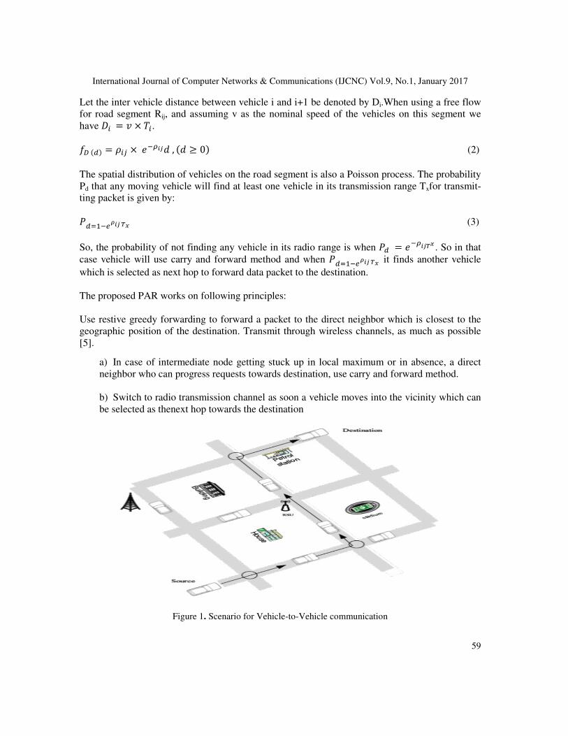
have assumed a road network of multiple segments forming diagonal streets in city or rural area.
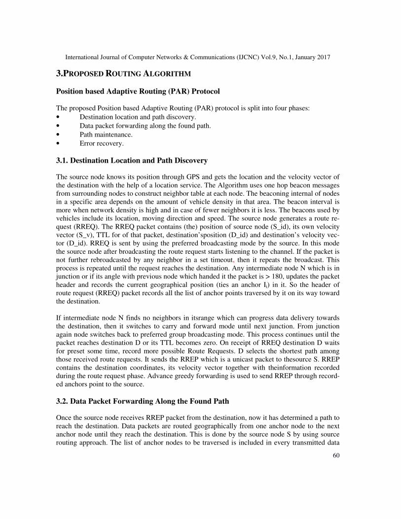
A typical network is shown in Figure 1. As shown, source vehicle and destination vehicle are
moving in different road segments. Source vehicle uses theintermediate vehicles for sending in-
formation to the destination vehicle. As shown in Figure 1, there are multiple paths possible from
the source vehicle to the destination vehicle. The proposed algorithm selects the most populated
path to send information to the destination.
We also assumed that the arrival rate of avehicle in the particular road segment Rij follows Pois-
son distribution with mean arrival rate λ vehicles per second. So the inter-arrival times of vehicles
are exponentially distributed with expected inter arrival time equal to 1/λ. Let the vehicle density
of the road segment Rij be ρij. We have also assumed that there is no congestion in road segment
Rij and vehicles travel at free flow at speed v meters per second. Then by assuming an M/M/1
queue model for a free flow road, we have arrival rate � = ��� × �. Let each vehicle has a radio
range Tx. Two vehicles are connected if the physical distance between two vehicles is less than
Tx. The inter-arrival time between two vehicles i and i+1 is denoted by the random variable Ti.
The density function of Tiis given by:
��� = � ���, � ≥ 0� (1)
International Journal of Computer Networks & Communications (IJCNC) Vol.9, No.1, January 2017
59
Let the inter vehicle distance between vehicle i and i+1 be denoted by Di.When using a free flow
for road segment Rij, and assuming v as the nominal speed of the vehicles on this segment we
have �� = � × ��.
���� = ��� × �����, � ≥ 0� (2)
The spatial distribution of vehicles on the road segment is also a Poisson process. The probability
Pd that any moving vehicle will find at least one vehicle in its transmission range Txfor transmit-
ting packet is given by:
�����
!��"# (3)
So, the probability of not finding any vehicle in its radio range is when �� = ����"# . So in that
case vehicle will use carry and forward method and when �����
!��"# it finds another vehicle
which is selected as next hop to forward data packet to the destination.
The proposed PAR works on following principles:
Use restive greedy forwarding to forward a packet to the direct neighbor which is closest to the
geographic position of the destination. Transmit through wireless channels, as much as possible
[5].
a) In case of intermediate node getting stuck up in local maximum or in absence, a direct
neighbor who can progress requests towards destination, use carry and forward method.
b) Switch to radio transmission channel as soon a vehicle moves into the vicinity which can
be selected as thenext hop towards the destination
Figure 1. Scenario for Vehicle-to-Vehicle communication
International Journal of Computer Networks & Communications (IJCNC) Vol.9, No.1, January 2017
60
3.PROPOSED ROUTING ALGORITHM
Position based Adaptive Routing (PAR) Protocol The proposed Position based Adaptive Routing (PAR) protocol is split into four phases:
• Destination location and path discovery.
• Data packet forwarding along the found path.
• Path maintenance.
• Error recovery.
3.1. Destination Location and Path Discovery
The source node knows its position through GPS and gets the location and the velocity vector of
the destination with the help of a location service. The Algorithm uses one hop beacon messages
from surrounding nodes to construct neighbor table at each node. The beaconing internal of nodes
in a specific area depends on the amount of vehicle density in that area. The beacon interval is
more when network density is high and in case of fewer neighbors it is less. The beacons used by
vehicles include its location, moving direction and speed. The source node generates a route re-
quest (RREQ). The RREQ packet contains (the) position of source node (S_id), its own velocity
vector (S_v), TTL for of that packet, destination’sposition (D_id) and destination’s velocity vec-
tor (D_id). RREQ is sent by using the preferred broadcasting mode by the source. In this mode
the source node after broadcasting the route request starts listening to the channel. If the packet is
not further rebroadcasted by any neighbor in a set timeout, then it repeats the broadcast. This
process is repeated until the request reaches the destination. Any intermediate node N which is in
junction or if its angle with previous node which handed it the packet is > 180, updates the packet
header and records the current geographical position (ties an anchor Ii) in it. So the header of
route request (RREQ) packet records all the list of anchor points traversed by it on its way toward
the destination.
If intermediate node N finds no neighbors in itsrange which can progress data delivery towards
the destination, then it switches to carry and forward mode until next junction. From junction
again node switches back to preferred group broadcasting mode. This process continues until the
packet reaches destination D or its TTL becomes zero. On receipt of RREQ destination D waits
for preset some time, record more possible Route Requests. D selects the shortest path among
those received route requests. It sends the RREP which is a unicast packet to thesource S. RREP
contains the destination coordinates, its velocity vector together with theinformation recorded
during the route request phase. Advance greedy forwarding is used to send RREP through record-
ed anchors point to the source.
3.2. Data Packet Forwarding Along the Found Path
Once the source node receives RREP packet from the destination, now it has determined a path to
reach the destination. Data packets are routed geographically from one anchor node to the next
anchor node until they reach the destination. This is done by the source node S by using source
routing approach. The list of anchor nodes to be traversed is included in every transmitted data
International Journal of Computer Networks & Communications (IJCNC) Vol.9, No.1, January 2017
packet by the source. PAR does it by greedily transferring information between two anchor
nodes. The authors of CAR [6] used anchor points to work with the Advance Greedy Forwarding
(AGF). AGF presumes that velocity vectors are exchanged by the source and the destinations.
The intermediate forwards the packet node to a neighbor closest to the
of forwarding a data packet to a neighbor that is geographically closer to the destination. Each
forwarding node relays to anchor if the distance is less than half coverage to avoid multiple a
tempts to gradually get closer to t
tion and the position of the next anchor point are separated by less than half of the node
age range. The process continues until the packet reaches its destination.
[6] (Shown in Figure 2) to help intermediate node N to find out if a message has reached a certain
anchor node or not. Two types of guards are used i.e., stationary guards and moving guards. A
standing guard represents temporary state information that is t
than to a specific node.If two intermediate node
is set [3, 6]. Anchor contains coordinates and velocity vector of the current node and previous
node. The nodes located in the area are kept alive by the guard. The beacon message of a node
contains the guard entry.
The new entry contains an id, a TTL counter, a guarded location coordinates and the radius. An
intermediate node with a guard can filter or redirect packets or a
which is further transmitted to a node geographically near to the destination [6]. Once TTL reac
es zero, the guard is removed from the node
not finding any neighbor, the algorith
packet. Based on the existing traffic pattern, a vehicle can find the next road to forward the packet
to reduce the delay [5, 8].
Figure
International Journal of Computer Networks & Communications (IJCNC) Vol.9, No.1, January 2017
packet by the source. PAR does it by greedily transferring information between two anchor
nodes. The authors of CAR [6] used anchor points to work with the Advance Greedy Forwarding
(AGF). AGF presumes that velocity vectors are exchanged by the source and the destinations.
The intermediate forwards the packet node to a neighbor closest to the next anchor point, instead
of forwarding a data packet to a neighbor that is geographically closer to the destination. Each
forwarding node relays to anchor if the distance is less than half coverage to avoid multiple a
tempts to gradually get closer to the next anchor point. Each forwarding node checks if its pos
tion and the position of the next anchor point are separated by less than half of the node
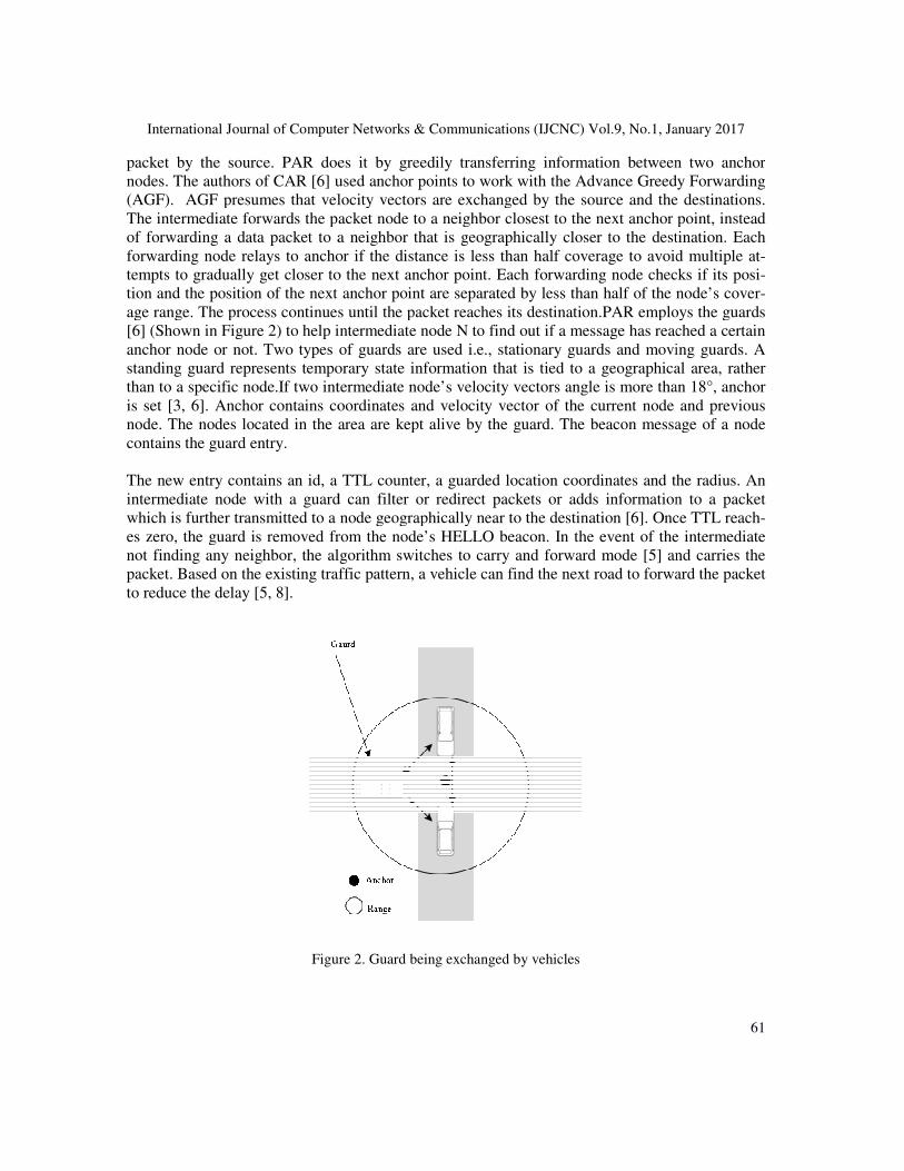
age range. The process continues until the packet reaches its destination.PAR employs the guards
[6] (Shown in Figure 2) to help intermediate node N to find out if a message has reached a certain
anchor node or not. Two types of guards are used i.e., stationary guards and moving guards. A
standing guard represents temporary state information that is tied to a geographical area, rather
than to a specific node.If two intermediate node’s velocity vectors angle is more than 18
is set [3, 6]. Anchor contains coordinates and velocity vector of the current node and previous
the area are kept alive by the guard. The beacon message of a node
The new entry contains an id, a TTL counter, a guarded location coordinates and the radius. An
intermediate node with a guard can filter or redirect packets or adds information to a packet
which is further transmitted to a node geographically near to the destination [6]. Once TTL reac
es zero, the guard is removed from the node’s HELLO beacon. In the event of the intermediate
not finding any neighbor, the algorithm switches to carry and forward mode [5] and carries the
packet. Based on the existing traffic pattern, a vehicle can find the next road to forward the packet
Figure 2. Guard being exchanged by vehicles
International Journal of Computer Networks & Communications (IJCNC) Vol.9, No.1, January 2017
61
packet by the source. PAR does it by greedily transferring information between two anchor
nodes. The authors of CAR [6] used anchor points to work with the Advance Greedy Forwarding
(AGF). AGF presumes that velocity vectors are exchanged by the source and the destinations.
next anchor point, instead
of forwarding a data packet to a neighbor that is geographically closer to the destination. Each
forwarding node relays to anchor if the distance is less than half coverage to avoid multiple at-
he next anchor point. Each forwarding node checks if its posi-
tion and the position of the next anchor point are separated by less than half of the node’s cover-
PAR employs the guards
[6] (Shown in Figure 2) to help intermediate node N to find out if a message has reached a certain
anchor node or not. Two types of guards are used i.e., stationary guards and moving guards. A
ied to a geographical area, rather
s velocity vectors angle is more than 18°, anchor
is set [3, 6]. Anchor contains coordinates and velocity vector of the current node and previous
the area are kept alive by the guard. The beacon message of a node
The new entry contains an id, a TTL counter, a guarded location coordinates and the radius. An
dds information to a packet
which is further transmitted to a node geographically near to the destination [6]. Once TTL reach-
of the intermediate
m switches to carry and forward mode [5] and carries the
packet. Based on the existing traffic pattern, a vehicle can find the next road to forward the packet
International Journal of Computer Networks & Communications (IJCNC) Vol.9, No.1, January 2017
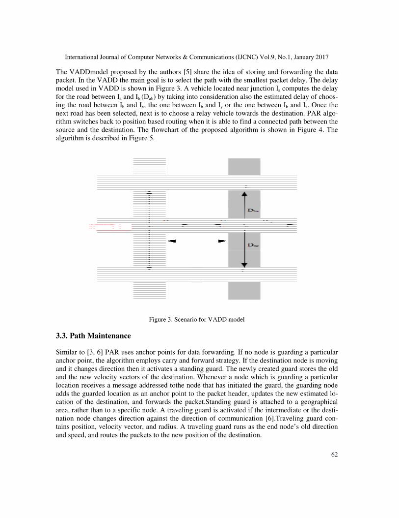
The VADDmodel proposed by the authors [5] share the idea of storing and forwarding the data
packet. In the VADD the main goal is to select the path with the smallest packet delay. The delay
model used in VADD is shown in Figure 3. A vehicle located near junction I
for the road between Ia and Ib (Dab
ing the road between Ib and Ix, the one between I
next road has been selected, next is to
rithm switches back to position based routing when it is able to find a connected path between the
source and the destination. The flowchart of the proposed algorithm is shown in Figure 4. The
algorithm is described in Figure 5.
Figure
3.3. Path Maintenance
Similar to [3, 6] PAR uses anchor points for data forwarding. If no node is guarding a particular
anchor point, the algorithm employs carry and forward strategy. If the destination node is moving
and it changes direction then it activates a standing guard.
and the new velocity vectors of the destination. Whenever a node which is guarding a particular
location receives a message addressed
adds the guarded location as an anchor point to the packet header, updates the new estimated l
cation of the destination, and forwards the packet.
area, rather than to a specific node. A traveling guard is activated if the intermediate
nation node changes direction against the direction of communication [6].Traveling guard co
tains position, velocity vector, and radius. A traveling guard runs as the end node
and speed, and routes the packets to the new positi
International Journal of Computer Networks & Communications (IJCNC) Vol.9, No.1, January 2017
d by the authors [5] share the idea of storing and forwarding the data
packet. In the VADD the main goal is to select the path with the smallest packet delay. The delay
model used in VADD is shown in Figure 3. A vehicle located near junction Ia computes the delay
ab) by taking into consideration also the estimated delay of choo
, the one between Ib and Iy or the one between Ib and I
next road has been selected, next is to choose a relay vehicle towards the destination. PAR alg
rithm switches back to position based routing when it is able to find a connected path between the
source and the destination. The flowchart of the proposed algorithm is shown in Figure 4. The
hm is described in Figure 5.
Figure 3. Scenario for VADD model
Similar to [3, 6] PAR uses anchor points for data forwarding. If no node is guarding a particular
anchor point, the algorithm employs carry and forward strategy. If the destination node is moving
and it changes direction then it activates a standing guard. The newly created guard stores the old
and the new velocity vectors of the destination. Whenever a node which is guarding a particular
location receives a message addressed tothe node that has initiated the guard, the guarding node
on as an anchor point to the packet header, updates the new estimated l
cation of the destination, and forwards the packet.Standing guard is attached to a geographical
area, rather than to a specific node. A traveling guard is activated if the intermediate
nation node changes direction against the direction of communication [6].Traveling guard co
tains position, velocity vector, and radius. A traveling guard runs as the end node’s old direction
and speed, and routes the packets to the new position of the destination.
International Journal of Computer Networks & Communications (IJCNC) Vol.9, No.1, January 2017
62
d by the authors [5] share the idea of storing and forwarding the data
packet. In the VADD the main goal is to select the path with the smallest packet delay. The delay
computes the delay
) by taking into consideration also the estimated delay of choos-
and Iz. Once the
choose a relay vehicle towards the destination. PAR algo-
rithm switches back to position based routing when it is able to find a connected path between the
source and the destination. The flowchart of the proposed algorithm is shown in Figure 4. The
Similar to [3, 6] PAR uses anchor points for data forwarding. If no node is guarding a particular
anchor point, the algorithm employs carry and forward strategy. If the destination node is moving
The newly created guard stores the old
and the new velocity vectors of the destination. Whenever a node which is guarding a particular
the node that has initiated the guard, the guarding node
on as an anchor point to the packet header, updates the new estimated lo-
Standing guard is attached to a geographical
area, rather than to a specific node. A traveling guard is activated if the intermediate or the desti-
nation node changes direction against the direction of communication [6].Traveling guard con-
s old direction
International Journal of Computer Networks & Communications (IJCNC) Vol.9, No.1, January 2017
63
3.4 Error Recovery
PAR algorithm uses preferred group broadcasting (PGB) to find connected paths between the
source and the destination. It uses store and forward technique until next junction if gets stuck up
in local maximum [2]. It uses only anchor nodes for data forwarding to the destination. Due to the
varying network density, routing errors may still cause problems. A message may reach the esti-
mated destination position but fails to find the node there. This happened as destination node be-
fore moving could not activate guard due to lack of neighbors in its radio range.The algorithm in
such cases uses store carry and forward method and hands over the packet as soon as it finds any
node moving in its vicinity and geographically closer to the destination. In another case, the in-
termediate node changes its direction from the direction ofthe communicationand does not find
any neighbor to activate a guard then it sends an error notification to the source node. Source
stops sending any data packet on the current discovered path and starts a new path discovery
process.
4.PERFORMANCE EVALUATION
To evaluate the proposed routing algorithm, PAR, we have used a simulator based on SUMO [18]
for traffic simulation and NS2 [20] for network simulation. We have also simulated GPSR [13],
GPCR [2], and CAR [6] for comparison with PAR algorithm.
4.1. Performance Metrics
The prime goal of any routing scheme is to increase packet delivery or service ratio and at the
same time reduce average packet delay betweenthe source and the destination. A good routing
algorithm should also have low message overhead. We use the following metrics for performance
evaluation.
• Service ratio (%). Itis defined as the ratio of the number of packets sent by the source ve-
hicle to the number of packets received by the destination vehicle. A better routing algorithm
should have a high service ratio.
• Average delay of a data packet (s). It is the average time taken by the packets from the
source vehicle to the destination vehicle.

International Journal of Computer Networks & Communications (IJCNC) Vol.9, No.1, January 2017
4.2 Experimental Setup
The experiment is based on a 2000x2000
roads, mobility pattern and vehicles are generated by using SUMO [18]. The generated mobility
trace is transformed into a data format that is used as input to NS2 [20]. To have different ne
work densities, the number of vehicles moving into the area has been varied between 10 and 60.
All these vehicles are moving forward and backward during the simulation to have the continuous
traffic flow in the street area. When one vehicle reaches the end of the r
hicle will move out of the grid area, it no more participates in the network. Various simulation
parameters with their corresponding values are listed in Table 1.
1. Node S get destination D location from location server
the starting words)
2. Construct neighbor table from one hop beacon packets
3. Forward the packet to the neighbor that is geographically closer to destin
tion
4. If intermediate nodes N towards destination is in range i.e.
go to Step 6
5. Otherwise, carry the packet until next junction
6. If node N is in junction or angle between communicating
7. Set anchors Ii and tie it to that particular locatio
8. Keep forwarding packet to the next node until reaches the destination D or
its TTL = 0
9. Destination D waits for some time record all possible Route Requests
10. Destination D selects the
11. Use the recoded anchors in packet header of Route Reply to transfer data
12. Set static guard for moving stationary source, intermediate or destination
node
13. Set moving guard for a node which moves opposite to the direction of
communication
International Journal of Computer Networks & Communications (IJCNC) Vol.9, No.1, January 2017
Figure 4. PAR algorithm
2000x2000m2 square street area in a grid layout. The street layout,
roads, mobility pattern and vehicles are generated by using SUMO [18]. The generated mobility
trace is transformed into a data format that is used as input to NS2 [20]. To have different ne
ities, the number of vehicles moving into the area has been varied between 10 and 60.
All these vehicles are moving forward and backward during the simulation to have the continuous
traffic flow in the street area. When one vehicle reaches the end of the road, which means the v
hicle will move out of the grid area, it no more participates in the network. Various simulation
parameters with their corresponding values are listed in Table 1.
get destination D location from location server (I have capitalized
neighbor table from one hop beacon packets
packet to the neighbor that is geographically closer to destin
intermediate nodes N towards destination is in range i.e.
carry the packet until next junction
node N is in junction or angle between communicating nodes is > 180
anchors Ii and tie it to that particular location
forwarding packet to the next node until reaches the destination D or
D waits for some time record all possible Route Requests
D selects the lowest delay path to send route reply to source
the recoded anchors in packet header of Route Reply to transfer data
static guard for moving stationary source, intermediate or destination
moving guard for a node which moves opposite to the direction of
International Journal of Computer Networks & Communications (IJCNC) Vol.9, No.1, January 2017
64
square street area in a grid layout. The street layout,
roads, mobility pattern and vehicles are generated by using SUMO [18]. The generated mobility
trace is transformed into a data format that is used as input to NS2 [20]. To have different net-
ities, the number of vehicles moving into the area has been varied between 10 and 60.
All these vehicles are moving forward and backward during the simulation to have the continuous
oad, which means the ve-
hicle will move out of the grid area, it no more participates in the network. Various simulation
(I have capitalized
packet to the neighbor that is geographically closer to destina-
nodes is > 180
forwarding packet to the next node until reaches the destination D or
lowest delay path to send route reply to source
the recoded anchors in packet header of Route Reply to transfer data
static guard for moving stationary source, intermediate or destination
moving guard for a node which moves opposite to the direction of

International Journal of Computer Networks & Communications (IJCNC) Vol.9, No.1, January 2017
Figure
Maximum Communication Range
International Journal of Computer Networks & Communications (IJCNC) Vol.9, No.1, January 2017
Figure 5. Flowchart of PAR algorithm
Table 1.Simulation Parameters.
Parameter Value
Simulation Time 1000s
Maximum Communication Range 200m
Vehicle Speed 30km/hour
Transmission Rate 11Mbps
International Journal of Computer Networks & Communications (IJCNC) Vol.9, No.1, January 2017
65

International Journal of Computer Networks & Communications (IJCNC) Vol.9, No.1, January 2017
Inter Vehicle Distance
Vehicle Beacon Interval
We have evaluated GPSR, GPCR, CAR and the proposed algorithm
formance.
4.3 Results
Effect of Vehicle Density on Service Ratio
Figure 6 shows the service ratio as a function of vehicle density in the area. The item size is set to
2500 bytes for the experiment. The vehicle density
mum 60 vehicles in the grid area. For all traffic volumes, GPSR does not perform well as it has a
poor delivery ratio. The GPSR does not perform well in this scenario because it uses
warding for selection of the next hop so more often gets stuck up in local maximum. The GPCR
however has a better delivery ratio as compared to GPSR and
the area. This uses perimeter coordinator routing for se
The CAR protocol uses preferred group broadcasting for route discovery and uses advance gre
dy forwarding for data forwarding so achieves high service ratio. The service of CAR increases
with number of vehicles as chances of void in the network are reduced.
Figure 6.
The performance of PAR is almost similar or better than CAR algorithm as the number of v
hicles increase from 10 to 60. The PAR algorithm uses two modes
in mode one, when a vehicle is not able to find a neighbor to route
International Journal of Computer Networks & Communications (IJCNC) Vol.9, No.1, January 2017
Item Size 10B-4KB
Inter Vehicle Distance 20m
Vehicle Beacon Interval 0.5sec
Packet TTL 128sec
GPSR, GPCR, CAR and the proposed algorithm, PAR, and compared the pe
Effect of Vehicle Density on Service Ratio
Figure 6 shows the service ratio as a function of vehicle density in the area. The item size is set to
experiment. The vehicle densityvaries between minimum 10 vehicles to max
mum 60 vehicles in the grid area. For all traffic volumes, GPSR does not perform well as it has a
poor delivery ratio. The GPSR does not perform well in this scenario because it uses
warding for selection of the next hop so more often gets stuck up in local maximum. The GPCR
however has a better delivery ratio as compared to GPSR and increaseswith number of vehicles in
the area. This uses perimeter coordinator routing for selection of next hop so better service ratio.
The CAR protocol uses preferred group broadcasting for route discovery and uses advance gre
dy forwarding for data forwarding so achieves high service ratio. The service of CAR increases
as chances of void in the network are reduced.
Figure 6. Effect of vehicle density on service ratio
The performance of PAR is almost similar or better than CAR algorithm as the number of v
hicles increase from 10 to 60. The PAR algorithm uses two modes and works similar to CAR [6]
in mode one, when a vehicle is not able to find a neighbor to route a packet to the destination and
International Journal of Computer Networks & Communications (IJCNC) Vol.9, No.1, January 2017
66
and compared the per-
Figure 6 shows the service ratio as a function of vehicle density in the area. The item size is set to
between minimum 10 vehicles to maxi-
mum 60 vehicles in the grid area. For all traffic volumes, GPSR does not perform well as it has a
poor delivery ratio. The GPSR does not perform well in this scenario because it uses greedy for-
warding for selection of the next hop so more often gets stuck up in local maximum. The GPCR
with number of vehicles in
lection of next hop so better service ratio.
The CAR protocol uses preferred group broadcasting for route discovery and uses advance gree-
dy forwarding for data forwarding so achieves high service ratio. The service of CAR increases
The performance of PAR is almost similar or better than CAR algorithm as the number of ve-
and works similar to CAR [6]
packet to the destination and
International Journal of Computer Networks & Communications (IJCNC) Vol.9, No.1, January 2017
switches to VADD [5] mode. The
radio range then it carries the packet until the next junction.
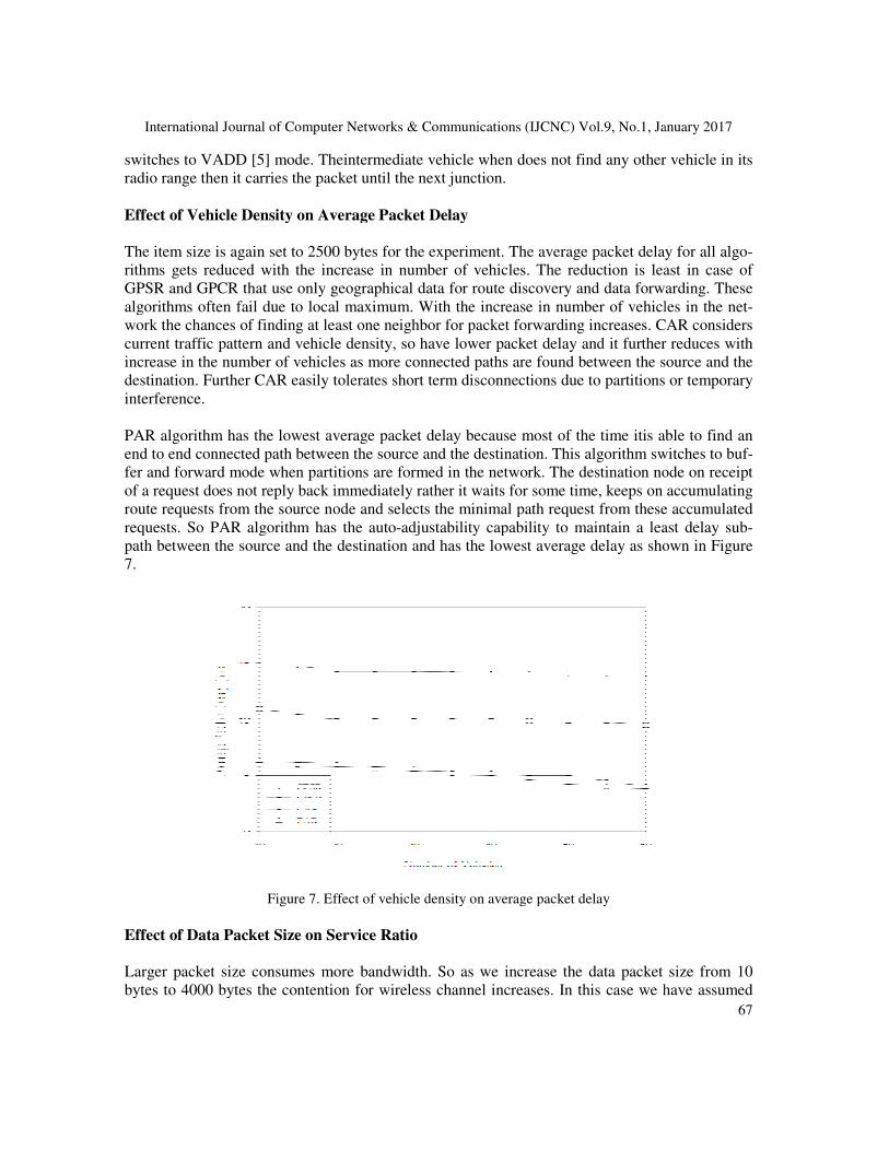
Effect of Vehicle Density on Average Packet Delay
The item size is again set to 2500 bytes for the experiment. The average packet delay for all alg
rithms gets reduced with the increase in number of vehicles. The
GPSR and GPCR that use only geographical data for route discovery and data forwarding. These
algorithms often fail due to local maximum. With the increase in number of vehicles in the ne
work the chances of finding at least on
current traffic pattern and vehicle density, so have lower packet delay and it further reduces with
increase in the number of vehicles as more connected paths are found between the source and the
destination. Further CAR easily tolerates short term disconnections due to partitions or temporary
interference.
PAR algorithm has the lowest average packet delay because most of the
end to end connected path between the source and
fer and forward mode when partitions are formed in the network. The destination node on receipt
of a request does not reply back immediately rather it waits for some time, keeps on accumulating
route requests from the source node and selects the minimal path request from these accumulated
requests. So PAR algorithm has the auto
path between the source and the destination and has the lowest average delay as
7.
Figure 7. Effect of vehicle density on average packet delay
Effect of Data Packet Size on Service Ratio
Larger packet size consumes more bandwidth. So as we increase the data packet size from 10
bytes to 4000 bytes the contention for wireless channel increases. In this case we have assumed
International Journal of Computer Networks & Communications (IJCNC) Vol.9, No.1, January 2017
Theintermediate vehicle when does not find any other vehicle in its
packet until the next junction.
Effect of Vehicle Density on Average Packet Delay
The item size is again set to 2500 bytes for the experiment. The average packet delay for all alg
rithms gets reduced with the increase in number of vehicles. The reduction is least in case of
GPSR and GPCR that use only geographical data for route discovery and data forwarding. These
algorithms often fail due to local maximum. With the increase in number of vehicles in the ne
work the chances of finding at least one neighbor for packet forwarding increases. CAR considers
current traffic pattern and vehicle density, so have lower packet delay and it further reduces with
increase in the number of vehicles as more connected paths are found between the source and the
stination. Further CAR easily tolerates short term disconnections due to partitions or temporary
PAR algorithm has the lowest average packet delay because most of the time itis able to find an
end to end connected path between the source and the destination. This algorithm switches to bu
fer and forward mode when partitions are formed in the network. The destination node on receipt
of a request does not reply back immediately rather it waits for some time, keeps on accumulating
from the source node and selects the minimal path request from these accumulated
requests. So PAR algorithm has the auto-adjustability capability to maintain a least delay sub
path between the source and the destination and has the lowest average delay as shown in Figure
Effect of vehicle density on average packet delay
Effect of Data Packet Size on Service Ratio
Larger packet size consumes more bandwidth. So as we increase the data packet size from 10
bytes to 4000 bytes the contention for wireless channel increases. In this case we have assumed
International Journal of Computer Networks & Communications (IJCNC) Vol.9, No.1, January 2017
67
ntermediate vehicle when does not find any other vehicle in its
The item size is again set to 2500 bytes for the experiment. The average packet delay for all algo-
reduction is least in case of
GPSR and GPCR that use only geographical data for route discovery and data forwarding. These
algorithms often fail due to local maximum. With the increase in number of vehicles in the net-
e neighbor for packet forwarding increases. CAR considers
current traffic pattern and vehicle density, so have lower packet delay and it further reduces with
increase in the number of vehicles as more connected paths are found between the source and the
stination. Further CAR easily tolerates short term disconnections due to partitions or temporary
is able to find an
the destination. This algorithm switches to buf-
fer and forward mode when partitions are formed in the network. The destination node on receipt
of a request does not reply back immediately rather it waits for some time, keeps on accumulating
from the source node and selects the minimal path request from these accumulated
adjustability capability to maintain a least delay sub-
shown in Figure
Larger packet size consumes more bandwidth. So as we increase the data packet size from 10
bytes to 4000 bytes the contention for wireless channel increases. In this case we have assumed
International Journal of Computer Networks & Communications (IJCNC) Vol.9, No.1, January 2017
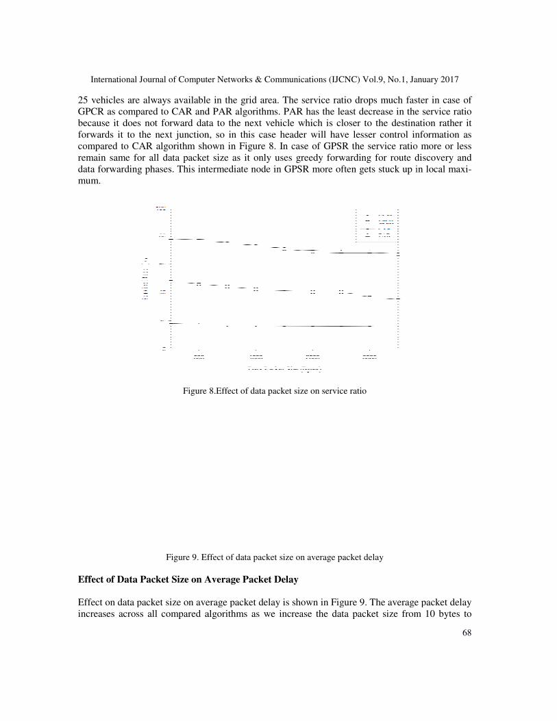
25 vehicles are always available in the grid area. The service ratio
GPCR as compared to CAR and PAR algorithms. PAR has the least decrease in the service ratio
because it does not forward data to the next vehicle which is closer to the destination rather it
forwards it to the next junction, so
compared to CAR algorithm shown in Figure 8. In case of GPSR the service ratio more or less
remain same for all data packet size as it only uses greedy forwarding for route discovery and
data forwarding phases. This intermediate node in GPSR more often gets stuck up in local max
mum.
Figure
Figure 9. Effect of data packet size on average packet delay
Effect of Data Packet Size on Average Packet
Effect on data packet size on average packet delay is shown in Figure 9. The average packet delay
increases across all compared algorithms as we increase the data packet size from 10 bytes to
International Journal of Computer Networks & Communications (IJCNC) Vol.9, No.1, January 2017
25 vehicles are always available in the grid area. The service ratio drops much faster in case of
GPCR as compared to CAR and PAR algorithms. PAR has the least decrease in the service ratio
because it does not forward data to the next vehicle which is closer to the destination rather it
next junction, so in this case header will have lesser control information as
compared to CAR algorithm shown in Figure 8. In case of GPSR the service ratio more or less
remain same for all data packet size as it only uses greedy forwarding for route discovery and
arding phases. This intermediate node in GPSR more often gets stuck up in local max
8.Effect of data packet size on service ratio
Effect of data packet size on average packet delay
Effect of Data Packet Size on Average Packet Delay
Effect on data packet size on average packet delay is shown in Figure 9. The average packet delay
increases across all compared algorithms as we increase the data packet size from 10 bytes to
International Journal of Computer Networks & Communications (IJCNC) Vol.9, No.1, January 2017
68
drops much faster in case of
GPCR as compared to CAR and PAR algorithms. PAR has the least decrease in the service ratio
because it does not forward data to the next vehicle which is closer to the destination rather it
in this case header will have lesser control information as
compared to CAR algorithm shown in Figure 8. In case of GPSR the service ratio more or less
remain same for all data packet size as it only uses greedy forwarding for route discovery and
arding phases. This intermediate node in GPSR more often gets stuck up in local maxi-
Effect on data packet size on average packet delay is shown in Figure 9. The average packet delay
increases across all compared algorithms as we increase the data packet size from 10 bytes to

International Journal of Computer Networks & Communications (IJCNC) Vol.9, No.1, January 2017
69
4000 bytes. The large data packet size will consume more bandwidth so less fewer wireless chan-
nels remains available. So more data packets get dropped as the bit error rate (BER) increases
which in turn increases the average packet delay in the network. In this case also we have taken
total 25 vehicles for the experiment. The experiment is carried out with a fixed transmission rate.
The GPCR observers more increase as compared to CAR and PAR both of them very much simi-
lar increase in average packet delay. This pattern is because the packet forwarding is not done
hop-by-hop rather it is done junction wise in CAR and PAR.
5. CONCLUSIONS In this paper we have proposed a Position based Adaptive Routing (PAR) scheme which is scala-
ble to different densities of vehicular ad hoc networks. This scheme uses preferred group broad-
casting for route discovery. In this mode, after broadcasting the request for route discovery the
source node starts listening to the channel. If the packet is not further rebroadcasted by any
neighbor in a set timeout, then it repeats the broadcast. This process is repeated until the request
reaches the destination. The destination keeps on accumulating route requests coming from dif-
ferent paths until apredefined time. It then chooses the least cost path as route reply. It uses the set
of traversed anchors for sending the unicast route reply to the source node. PAR uses advance
greedy forwarding for data forwarding and greedily forwards the data packet to the next anchor
towards destination node. It switches to carry and forward mode once it finds gaps in the network.
The node buffers the packet till next junction and switches back to position based scheme and
greedily forwards it to the next node in its range which is closest to the destination. To have an
end to end connected path, it uses guards to guard anchors tied to the different junction(s) and
geographical locations in the network. The algorithm is scalable and exploits (the) advantages of
existing techniques already developed for the specific scenarios in VANET.
REFERENCES [1] Z. Haas, J. Halpernand and L. Li, “Gossip Based Ad Hoc Routing,” Proceedings of IEEE INFOCOM,
pp. 1707–1716, 2002.
[2] C. Lochert, M. Mauve, H. Hartenstein and S. Holger, “Geographic Routing in City Scenarios,” ACM
SIGMOBILE Mobile Computing and Communications Review, Vol. 9, No. 1, pp. 69-72, 2005.
[3] V. Naumou, R. Baumann and T. Gross, “An Evaluation of Inter-Vehicle Ad Hoc Networks Based on
Realistic Vehicular Traces,” ACM International Symposium on Mobile Ad Hoc Networking and
Computing, Florence, Italy, pp. 108-119, 2006.
[4] M. Jerbi, S. Senouci, M. Meraihi and R. Ghamri, “An Improved Vehicular Ad Hoc Routing Protocol
for City Environments,” IEEE International Conference on Communications (ICC 2007), Glasgow,
Scotland, pp. 3972-3979, 24-28 June 2007.
[5] J. Zhao and C. Cao, “VADD: Vehicle-Assisted Data Delivery in Vehicular Ad Hoc Networks,” IEEE
International Conference on Computer Communications (INFOCOM 2006), pp. 1-12, 2006.
[6] V. Naumov, and T. Gross, “Connectivity Aware Routing (CAR) in Vehicular Ad Hoc Networks,”
IEEE International Conference on Computer Communications (INFOCOM 2007), pp. 1919-1927,
2007.
[7] K. Katsaros, M Dianati and K. Roscher, “A Position-Based Routing Module for Simulation of
VANETs in ns-3,” SIMUTOOLS '12, pp 345-352, 2012.
[8] M. Boban, G. Misek and O. Tonguz, "What is best acheivableQos for Unicast routing in VANETs ?,”
IEEE GLOBECOM Workshops, pp.1-10, Jan 2008.

International Journal of Computer Networks & Communications (IJCNC) Vol.9, No.1, January 2017
70
[9] S. Wang, "The Effects Of Wireless Transmission Range On Path Lifetime In Vehicle-Formed Mobile
Ad-Hoc Networks On Highways,” IEEE International Conference on Communications, Vol. 5, pp.
3177-3181, May 2005.
[10] D.E. Cooper, P. Ezhilchelvan and I. Mitrani, “A Family of Encounter-Based Broadcast Protocols for
Mobile Ad-Hoc Networks,” International Workshop of the EURO-NGI Network of Excellence, pp.
235-248, June 2004.
[11] F. Bonnet, P. Ezhilchelvan and E. Vollset, “Quiescent Consensus in Mobile Ad- Hoc Networks Using
Eventually Storage-Free Broadcasts,” Annual ACM Symposium on Applied Computing, pp. 670-674,
April 2006.
[12] O. Abedi, M. Fathy and J. Taghiloo, “Enhancing AODV Routing Protocol Using Mobility Parameters
in VANET,” IEEE/ACS International Conference on Computer Systems and Applications, pp. 229-
235, 2008.
[13] B. Karp and H. T. Kung, “Greedy Perimeter Stateless Routing for Wireless Networks,” Proc. of 6th
Annual ACM/IEEE Int. Conf. on Mobile Computing, pp. 243-54, Aug 2000.
[14] C. Lochert, H. Hartenstein, J. Tian, H. Fubler, D. Hermann and M. Mauve, “A Routing Strategy for
Vehicular Ad Hoc Networks in City Environments,” Proc. of IEEE on Intelligent Vehicles Sympo-
sium, pp. 156-161, June 2003.
[15] B. Seet, G. Liu, B. Lee, C. Foh, K. Wong and K. Lee, “A-STAR: A Mobile Ad Hoc Routing Strategy
for Metropolis Vehicular Communications,” Lecture Notes in Computer Science, Vol. 3042, pp. 989-
999, Jan 2004.
[16] J. Tian, L. Han, K. Rothermel and C. Cesh, “Spatially Aware Packet Routing for Mobile Ad Hoc Inter
Vehicle Radio Networks,” Proc. of IEEE on Intelligent Transportation systems, Vol. 2, pp. 1546-
1551, Oct 2003.
[17] A. Vahdat and D. Becker, “Epidemic Routing for Partially Connected Ad Hoc
[18] MOVE (Mobility model generator for vehicular networks), http://lens.csie.ncku.edu.tw/.
[19] NoW (Network on Wheels), http://www.network-on-wheels.de.
[20] NS2 (the Network Simulator), http://www.isi.edu/nsmam/ns/.