Embed Size (px)
Citation preview
1
ApplicationInformation
Hardness03/01
Information:Product Sales Price Application
-- -- -- H-10
PPoorrttaabblleeHHaarrddnneessss TTeessttiinngg
-- AApppplliiccaattiioonn GGuuiiddee --
Dr. Stefan Frank(February 2001)

2
ApplicationInformation
Hardness03/01
Information:Product Sales Price Application
-- -- -- H-10
1. Introduction ................................................................................................................. 31.1 What is hardness? 41.2 Why hardness testing? 41.3 On-site hardness testing? 4
2. The UCI Method (MIC 10) .......................................................................................... 52.1 Selecting the MIC probe 6
3. The Rebound method................................................................................................. 8
4. Application ................................................................................................................ 104.1 Selecting the method 104.2 Indentation size 114.3 Test piece mass requirements 144.4 Wall thickness requirements 154.5 Surface quality / roughness 164.6 Handling, Alignment and Fixing 174.7 Calibration 184.8 Verifying instrument performance 20
5. Solution of the test task ............................................................................................ 21

3
ApplicationInformation
Hardness03/01
Information:Product Sales Price Application
-- -- -- H-10
1. Introduction
Mobile hardness testing is on the advance: In these times of cost pressures and higher quality require-ments there is a quick and economical supplement to stationary hardness testing in the modern produc-tion process. The application possibilities are far ranging, this includes large as well as small parts, andespecially applies to positions which are difficult to access.There are two different physical methods which are particularly recognized in the practical field: the staticUCI method and dynamic rebound hardness testing. The decision as to which method is used mainly de-pends on the test task.
Fig. 1: Hardness testing with a UCI instrument on the tooth flanks of a pinion shaft.
Fig. 2: Hardness testing with a rebound tester on the drive wheel of a large hydraulic digger.
Krautkramer offers two series of portable hardness testers, one operating on the UCI Ultrasonic ContactImpedance principle (MIC 10) and the other on the rebound principle (DynaMIC and DynaPOCKET).
This paper explains the basic principles of both test methods and compares, using examples from thepractical field (e.g. hardness testing in the heat affected zone of welds), the application possibilities of bothmethods. In addition to this, the subjects critically discussed are the factors of influence on hardness test-ing, such as surface preparation or the wall thickness of parts to be tested, e.g. pipelines.

4
ApplicationInformation
Hardness03/01
Information:Product Sales Price Application
-- -- -- H-10
1.1 What is hardness?
With regards to metals, hardness has always been a subject of much discussion among technical people,resulting in a wide range of definitions. Hardness properties include such varied attributes as resistance toabrasives, resistance to plastic deformation, high modulus of elasticity, high yield point, high strength,absence of elastic damping, brittleness or lack of ductility.To a metallurgist, hardness is a material’s resistance to penetration. In general, an indenter is pressed intothe surface of the material to be tested under a specific load for a definite time interval, and a measure-ment is made of the size or depth of the indentationHardness is not a fundamental property of a material, but a response to a particular test method. Basicallyhardness values are arbitrary, and there are no absolute standards for hardness. Hardness has no quan-titative value, except in terms of a given load applied in a specific, reproducible manner and with a speci-fied indentor shape.Static indentation tests in which a ball, cone or pyramid penetrates into the surface of the material beingtested are widespread. The relationship of load to the area or depth of indentation is the measure of hard-ness, such as in common bench-top Brinell, Rockwell, Vickers or Knoop hardness testers.The different methods and differently shaped indenters used by e.g. Brinell and Rockwell produce dis-similar responses of the material under test. Tables relating to HRC and HB values are only approxima-tions – there exists no mathematical equation to transfer measurements from one scale to another. So-called conversion tables have to be determined empirically by experimental evaluation of a specific mate-rial’s hardness with the different test methods. To compare the hardness of two different samples, bothmust be measured using the same hardness scale, or a scale must be developed to convert from onemeasurement to the other. Hardness scales are only in relationship to themselves!
1.2 Why hardness testing?
In manufacturing applications, materials are primarily tested for two reasons: either to research the char-acteristics of a new material or as a quality check to ensure that the sample meets a particular specifica-tion.
1.3 On-site hardness testing?
Conventional hardness testers such as Rockwell, Brinell or Vickers machines require the test piece bebrought to the testing device; but this is not always possible. Portable testing devices have been devel-oped that permit in-situ hardness measurements.One popular device measures the frequency shift of a resonating rod with a Vickers-diamond tip, whichoccurs when the diamond penetrates into the test material by applying a specific test load. The frequencyshift is evaluated and electronically converted to hardness value displayed on the LCD. The MICRODUR10 instrument (Krautkramer) works according this method, the so called UCI (Ultrasonic Contact Imped-ance) method.Another well-known principle for portable hardness testers is the rebound method. The DynaMIC orDynaPOCKET (Krautkramer), for example, measures the velocity of a propelled impact body directly be-fore and after the impact onto the test material’s surface. The ratio between both velocities indicates thehardness of the material, which can be converted into different scales by using conversion tables stored inthe instrument for different materials.

5
ApplicationInformation
Hardness03/01
Information:Product Sales Price Application
-- -- -- H-10
2. The UCI Method (MIC 10)
As in standard Vickers or Brinell hardness testing, the question as to the size of the test indentation in thematerial generated by a certain test load also arises in Vickers hardness testing according to the UCI (Ul-trasonic Contact Impedance) method. However, the diagonals of the test indentation, which have to beknown in order to determine the Vickers Hardness value, are not evaluated optically as usual, but theindentation area is electronically detected by measuring the shift of an ultrasonic frequency. This can beillustrated by a small imaginary experiment.A UCI probe typically consists of a Vickers diamond attached to the end of a metal rod (Fig. 3). This rod isexcited into longitudinal oscillation at about 70 kHz by piezoelectric transducers. Imagine instead of themetal rod (we refer to it as oscillation rod) a large spiral spring held at the end and oscillating at a resonantfrequency of 70 kHz at the free end (Fig. 4).At the very top of this spring (free end) there is a contact plate, the Vickers diamond. The test material,with which the Vickers diamond comes into contact, can also be imagined as being a system of smallerspiral springs positioned vertically to the surface - an atomic bonding, two atoms inter-linked via a "spring".If only one of these "atomic springs" is touched by the Vickers diamond in this imaginary experiment - likevery hard material in which the diamond only slightly penetrates and thus produces a small indentation –then an additional spring, i.e. mass, is coupled to the large spiral spring. By doing this, the resonant fre-quency shifts due to this additional mass / spring.
Fig 3: Schematic description of the UCI probe Fig 4. UCI principle in an imaginary experiment: an oscillating spring in contact with material. The spring symbolizes the oscillating rod, the contact plate symbolizes the diamond, the material springs symbolize the material and its elastic constants.
This frequency shift will become greater when additional "springs" are touched, that means if the diamondpenetrates deeper into a material of medium hardness, and the test indentation becomes larger. Analo-gously, the largest frequency shift is produced by soft test materials; the diamond penetrates deeper intothe material and leaves a large indentation.This is the secret of UCI hardness testing: the frequency shift is proportional to the size of the test inden-tation produced by the Vickers diamond. Equation (1) describes this basic relation in comparison to thedefinition of the Vickers hardness value.
Piezo Transducer
Vickers Diamond
Oscillating Rod
Piezo Receiver
Material
Fixture
Spring
Material Springs
Contact Plate

6
ApplicationInformation
Hardness03/01
Information:Product Sales Price Application
-- -- -- H-10
AEf elast ⋅≈∆ AFHV = (1)
Equation 1: The Frequency shift is proportional to the indentation size of a Vickers indentor.f∆ = frequency shift, A = area of indentation, elastE = Young’s modulus, HV = Vickers hardness
value, and F= Force applied in the Vickers hardness test.
The frequency shift nevertheless also depends on the Young's modulus of elasticity, which is a materialconstant such as the spring constant in our mental experiment. For the practical application of the UCI-method the Young's modulus, therefore, has to be considered. The instrument has to be calibrated whenthe hardness of different materials with different values of the Young's modulus has to be determined.
After completing the calibration, the UCI method can be used for all materials showing this modulus ofelasticity. When being manufactured, the probes are calibrated on low-alloyed or unalloyed steels; how-ever, modern test instruments can be calibrated quickly, also at the test location, to other materials aswell, such as titanium or copper.
2.1 Selecting the MIC probe
To carry out the UCI principle, a probe containing a rod with a Vickers diamond attached to the contactend is resonated by piezoelectric ceramics at an ultrasonic frequency.A spring applies the load and the frequency of the rod changes in proportion to the contact area of theindentation produced by the Vickers diamond. Therefore the hardness value is not visually determinedby the diagonals of the indent, as would normally be the case with a workbench hardness tester, but byan electronic measurement of the frequency shift within seconds.The instrument constantly monitors the frequency, performs the calculation and instantaneously displaysthe hardness value.The UCI method is best suited for testing homogeneous materials. Five different loads are employed bythe various models of UCI probes.
100
300
500
700
900
2 2,5 3 3,5 4 4,5 5Frequency shift [kHz]
HV
Fig 5: Vickers Hardness value versus frequency shift of the oscillating rod.

7
ApplicationInformation
Hardness03/01
Information:Product Sales Price Application
-- -- -- H-10
Load Available Models Advantage or Benefit Typical Applications98 N MIC-2010
Standard LengthHandheld Style
Largest indentation; requiresminimal surface preparation
Small forgings, weld testing, HAZ
50 N MIC-205Standard LengthHandheld Style
MIC-205LExtended LengthHandheld Style
MIC 205SShort ProbeHandheld Style
Solves most general applications
30mm extended length
Reduced length, 90 mm, electron-ics in separate housing
Induction or carburized machinedparts, e.g. camshafts, turbines,weld inspection, HAZ.
Measurement in grooves, geartooth flanks and roots
Turbine blades,inside tubes with ∅ > 90mm
10 N MIC-201Standard LengthHandheld Style
MIC-201LExtended LengthHandheld Style
MIC 201SShort ProbeHandheld Style
Load is easy to apply; providescontrol to test on a sharp radius
Measurement on complicatedgeometries
Reduced length, 90 mm, electron-ics in separate housing
Ion-nitrided stamping dies andmolds, forms, presses, thin walledparts
Bearings, tooth flanks
Turbine blades,inside tubes with ∅ > 90 mm
8 N MIC-211Motor Probe Style
Use with urethane fixtures forcomplex shapes
Finished precision parts, gears,bearing raceways
3 N MIC-2103Motor Probe Style
Shallowest indentation Layers, e.g. copper or chromiumlayers on steel cylinders(≥ 40 µm),Copper Rotogravure cylinders,Coatings, Hardened layers(≥ 20 µm)
Table 1 UCI (MIC 10) probe models, their benefits and typical applications.

8
ApplicationInformation
Hardness03/01
Information:Product Sales Price Application
-- -- -- H-10
3. The Rebound method(DynaMIC and DynaPOCKET Hardness Testing according ASTM A 956-00)
Hardness testers using Leeb's method operate ina slightly different manner. Although the size of thetest indentation generated is connected with thematerial hardness even in this case, it is indirectlymeasured via the loss of energy of a so-calledimpact body. Fig. 6 illustrates the physical principleof measurement. A mass is accelerated to thesurface of the test object and impinges on it at adefined speed, i.e. kinetic energy. The impactcreates a plastic deformation of the surface, i.e. anindentation, due to which the impact body losespart of its original speed - or energy. It will losemore speed by creating a bigger indentation and,thus, at softer material. Technically, this principle
of measurement is implemented by means of an impact body which has a spherical tungsten carbide tipand which is accelerated onto the test surface by spring force.The velocities after and before the impact are each measured in a non-contact mode. This is done by asmall permanent magnet within the impact body (Fig. 7) which generates an induction voltage during itspassage through a coil, with this voltage being proportional to the speed (Fig. 8).The inventor of this method, D. Leeb, defined his own hardness value, the Leeb hardness value. TheLeeb hardness value, HL, is calculated from the ratio of the impact and rebound speed according to:
1000vv
HLIR ⋅= (2)
RI v,v = speed before / after the impact
Impact Rebound
Fig. 6: The basic principle of the rebound hardness testd= diameter of indentation, Epot= potential energy,Ekin= kinetic energy.
Epot = mghI
Epot = mghR
Ekin = mvR2/2
Ekin = mvI2/2
d
hI
hR
vR
vI
Fig. 7: Cross-cut of a typical impact device Fig. 8: Voltage signal generated by the impact bodytraveling through the coil. The signal is shownbefore and after the impact.

9
ApplicationInformation
Hardness03/01
Information:Product Sales Price Application
-- -- -- H-10
You might asked yourself: "Who wants to measure the hardness value in Leeb?". The answer is: as amatter of fact, anybody who uses the rebound hardness testing method does it because the Leeb hard-ness value is, by definition in the equation (2), the actual physical measurement value behind this method.However, nearly no user indicates the Leeb hardness value HL in his specifications or test reports. Wemostly convert into the required hardness scales (HV, HB, HS, HRC, HRB, N/mm2). For this reason, onlyconversion brings the rebound hardness method to life. Therefore, conversion tables, like in Fig. 9, arestored in all instruments.
Fig. 9: Conversion of Hardness Leeb, HL, into HRC as a typical example for conversion tables stored in reboundhardness testers. These curves are experimentally generated by material samples of different hardnessmeasured by rebound and Rockwell tests.
The series of rebound hardness testers includes the DynaMIC and DynaMIC DL instruments and threemodels of interchangeable impact devices as well as the compact DynaPOCKET hardness tester.To apply the principle, an impact device uses a spring to propel an impact body through a guide tube to-wards the test piece. As it travels towards the test piece, a magnet contained within the impact body gen-erates a signal in a coil encircling the guide tube. After the impact, it rebounds from the surface inducing asecond signal into the coil. The Krautkramer instrument calculates the hardness value using the ratio ofthe voltages and analyzes their phases to automatically compensate for changes in orientation. Due to thepatented signal processing there is no need for any manual correction for the impact direction. TheKrautkramer hardness tester DynaMIC and DynaPOCKET offer this autobalancing feature.Application solutions are determined by the force and indenter of the impact body. The operator can selectfrom three models of impact devices for the DynaMIC (Dyna D, Dyna E and Dyna G) as well as theDynaPOCKET.
Model Indenter ImpactEnergy
Typical Applications
Dyna D 3 mm Tungsten Carbide Ball 12 N mm General purpose testing of homogeneous materialDyna E 3 mm Diamond 12 N mm >50 HRC, e.g. forged and hardened steel mill rollsDyna G 5 mm Tungsten Carbide Ball 90 N mm <650 HB, e.g. Large castings and forgings, lower
surface requirements (n9 as opposed to n7 withDyna D)
DynaPOCKET 3 mm Tungsten Carbide Ball 12 N mm Compact, integrated rebound hardness tester
Table 2: DynaPOCKET and DynaMIC Series Impact Devices, their benefits and typical applications.
10,0
20,0
30,0
40,0
50,0
60,0
70,0
80,0
500 600 700 800 900
HLD
HRC

10
ApplicationInformation
Hardness03/01
Information:Product Sales Price Application
-- -- -- H-10
4. Application
4.1 Selecting the method
The UCI method is recommended for testing fine grained material having any shape and size. It is espe-cially used where material properties are to be processed with narrow tolerances, e.g. for determination ofstrain hardening on drop forged parts. Rebound hardness testing is carried out on large, coarse grainedmaterials, forged parts and all types of casted materials because the spherical tip of the impact deviceproduces a rather larger indent than the Vickers diamond and therefore processes the characteristics ofthe casting structure better. With the small indent of the Microdur UCI probes, determination of the hard-ness can be made on welded parts in the critical area of the weld, the heat affected zone (HAZ). A num-ber of probes and impact devices having different test loads open up different areas of application.
(++ especially suited / + well suited / o suited sometimes / - not recommended)
Table 3: Applications for UCI and rebound hardness testing.
For rebound hardness testing, impact devices are offered with different test loads. In addition to the im-pact device Dyna D, which covers standard applications, there is the impact device Dyna G, having animpact energy which is nine times higher and has a larger tungsten carbide tip, designed for testing solidcasted or forged parts; the impact device Dyna E is recommended for parts above a hardness of 650HV/56 HRC and has a diamond tip instead of a tungsten carbide tip.
Application UCI testing Rebound testing
Solid parts + ++
Coarse grain materials - ++
Steel and aluminum casted alloys o ++
HAZ with welds ++ -
Tubes: wall thicknesses > 20 mm ++ ++
Tubes: wall thicknesses < 20 mm ++ -
Inhomogeneous surfaces - +
Thin layers ++ -
Difficult to access positions ++ +

11
ApplicationInformation
Hardness03/01
Information:Product Sales Price Application
-- -- -- H-10
4.2 Indentation size
In general, the larger the area sampled by an indentation the more consistent the test results. The varia-tions in microstructure of non-homogeneous materials or those comprised of large coarse grains are av-eraged out and consistent hardness values can be achieved. Also a larger indentation puts fewer de-mands on the surface finish and requires less surface preparation.
Fig. 10: Comparison of indentation width for Dyna D impact device and MIC 2010, MIC 205, MIC 201probe
In comparison, the indentations yielded by the various impact devices of rebound testers are much largerthan those created by any UCI probe. When testing large castings and forgings the rebound tester is rec-ommended. Testing small homogenous materials that are surface hardened require the shallower inden-tations produced by UCI probes. Table 4 a + b are provided to compare the indentation size of reboundimpact devices and UCI probes at three levels of hardness.
Dyna G5 mm ball,90 N mm
Dyna D3 mm ball12 N mm
MIC 201098 N
MIC 20550 N
MIC 20110 N
MIC 21033 N
64 HRC 350 152 107 48 2555 HRC 898 449 175 124 56 2830 HRC 1030 541 249 175 79 41
Table 4a: Approximate indentation width (in µm) at different hardness levels.
Dyna G5 mm ball,90 N mm
Dyna D3 mm ball12 N mm
MIC 201098 N
MIC 20550 N
MIC 20110 N
MIC 21033 N
800 HV 16 22 16 7 4600 HV 63 28 25 20 9 5300 HV 83 35 35 25 11 6
Table 4b: Approximate indentation depth (in µm) at different hardness levels.
Relation of Penetration Depth and Minimum Thickness for Coatings
For Vickers hardness testing, the thickness or depth of hardened layer or coating like chromium on steelrolls must be substantial enough to support the indentation. As a rule, the thickness should be a minimumof ten times the indentation depth.

12
ApplicationInformation
Hardness03/01
Information:Product Sales Price Application
-- -- -- H-10
You can easily calculate the penetration depth of the Vickers diamond if you know the force of the probeand approximately the hardness by using equation 2. This formula is just based on geometry of the Vick-ers diamond. Therefore, the equation is only valid for a Vickers test.(Remember: Newton, 10 N ≈ 1 kgf.)
Equation 2: Penetration depth of a Vickers diamond
Fig. 11: Penetration depth of the Vickers-Diamond vs. the hardness for different test loads
Penetration depth]HV[HardnessVickers
]N[LoadTest062.0]mm[d ⋅=
Minimum thickness d10s ⋅=

13
ApplicationInformation
Hardness03/01
Information:Product Sales Price Application
-- -- -- H-10
Hardness Testing at HAZ
Hardness testing on welded parts is another excellent example of showing the importance of the indenta-tion size. Hardness measurements , especially in the HAZ determine whether the welding was done prop-erly or not. For example, high martensite content in the HAZ very often causes cracks at the weld. A highhardness peak in the HAZ, therefore, gives a good indication about the material’s condition.Of course, only those techniques can be used which just measure in this small critical area of about 0.2 to0.3 mm. Using Brinell or even the Telebrineller (which is still very often used to check welds on pipes etc.)results in quite large indentation sizes. Obviously, those measurements will give just an average and,therefore, a lower hardness value than the “real hardness” of the HAZ, due to the overlapping measure-ment zone with zones of lower hardness. This may lead to the conclusion that no further heat treatment ofthe weld will be necessary. Whether this was a wise decision or not must be left to the opinion of thereader.It clearly comes out that just Vickers hardness testing with low loads (HV5 or HV10) results in indentationsizes which are located within the small critical area.
Fig. 12: Hardness Testing at a heat affected zone (HAZ)

14
ApplicationInformation
Hardness03/01
Information:Product Sales Price Application
-- -- -- H-10
4.3 Test piece mass requirements
Consideration must be given to the mass of the test piece. Although the requirement for the Leeb methodis much greater than that for the UCI method, both methods can be influenced by the weight and thick-ness of the test piece.The Leeb method creates a large force of short duration during the impact. Thin and lightweight materialsflex causing erroneous values. A solution for testing small simple shaped components is a machined sup-port that matches the contour of the back surface of the part. The support reinforces the part to make itridged. Extremely thin materials may also require the use of a light grease or paste to couple the part tothe support.The UCI method is based on measuring a frequency shift. Parts less than about 0.3 kg can go into self-oscillation causing erroneous or erratic readings. The support plate and coupling technique describedabove is also an effective method to make small components non-resonating. If the use of a support plateis not feasible, select a probe with a lower load to reduce the effects of self oscillation.Table 5 is provided as a guideline for determining support requirements. How precisely the supportmatches the contour of the part determines its effectiveness.
Dyna D & E DynaG UCI Probes
No support required > 5 Kg > 15 Kg > 0.3 KgRequires Support 2 to 5 Kg 5 to 15 Kg 0.1 to 0.3 KgRequires Support & coupling paste .05 to 2 Kg .5 to 5 Kg 0.01 to 0.1 Kg
Table 5: Mass Requirements

15
ApplicationInformation
Hardness03/01
Information:Product Sales Price Application
-- -- -- H-10
4.4 Wall thickness requirements
Wall thickness of tubes, pipelines or valves are critical for portable hardness testing. As an example, athin wall will start to oscillate like the skin of a drum when it’s hit by the impact body in a rebound test.
The test object’s minimum mass is indicated for the rebound method which should not exceed the specifi-cations given in Table 5. But the wall thickness also plays an important part in selection of the testmethod. It can influence the hardness value even when the test object is solid and weighs a few tons.
Table 6: Recommended minimum wall thickness. Certain geometries could stiffen the test piece allowingmeasurement of lower wall thickness’.
Despite the impact device’s small mass and the low impact energy, there is a high force of about 900 Nproduced at the time of impact (as a comparison: the maximum force of a MIC UCI probe is 98 N). That issufficient to produce vibrations, the same as the skin of a drum, with a wall thickness of under 20 mm -which can cause smaller hardness values and large amounts of scatter. In such cases, preference shouldbe given to the UCI method.
Fig.13 shows the hardness values measured by a standard Vickers test with a 10 kp (98 N) force andthose values measured by a Dyna D impact device.For a wall thickness higher than 20 mm, both tests show the same results. Below 20 mm, the Vickersvalue measured by the rebound test is lower than the true value resulting in a deviation from the horizontalline.
Hardness testingmethod
Wall thicknessin mm
Wall thicknessin inches
Rebound 20 mm 0.79
UCI 2-3 mm 0.08 – 0.12
Fig. 13: Standard Vickers values (HV10) compared with Rebound values (HVR) for different wall thick-ness’ of tubes.

16
ApplicationInformation
Hardness03/01
Information:Product Sales Price Application
-- -- -- H-10
4.5 Surface quality / roughness
All hardness testing methods require smooth surfaces free of oxide scale, paint, lubricants, oil, plasticcoating due to corrosion protection or metal coating for better conductivity. The indentation depth shouldbe large in comparison to the surface roughness.If surface preparation is necessary, care must be taken not to alter the surface hardness by overheating orcold working. These values are based on values given in the specific hardness testing standards. Morepractical results can be achieved by using a battery driven, high speed (>12000 rpm) handheld grinder.Use 180 grid to get a smooth surface. It takes just 10 seconds.
Fig. 14: Range of measured Hardness values versus surface preparation. HVR indicates converted Vickershardness values measured by rebound hardness testing

17
ApplicationInformation
Hardness03/01
Information:Product Sales Price Application
-- -- -- H-10
4.6 Handling, Alignment and Fixing
Move the MIC handheld probe with slow and steady speed. The probe should be rectangular with respectto the surface. Maximum angular deviation from the straight axis should be less than 5 degrees. Avoidturning, don’t drill. There should be no lateral forces on the diamond.The DynaMIC impact device must be within two or three degrees of being perpendicular to the surface.Support rings for the impact devices and probe shoes for the UCI probe ensure proper alignment.
The standard support rings provided with each Dyna D and Dyna E are used to test convex or concaveradii greater than 30 mm. The larger diameter of the Dyna G standard support ring requires the radius tobe greater than 50 mm. Support rings for the Dyna D and Dyna E impact devices are available to coverthe range of r = 10-30 mm for testing the ID’s or OD’s of cylindrical and spherical shaped parts (see Dyna41 and Dyna 42). Customized support rings are available on request.
For standard length UCI probes, the MIC-270 and MIC-271 probe shoes are offered as accessories. TheMIC-271 is recommended for testing cylindrical parts with radii of 3-75 mm. The flat probe shoe is de-signed to test flat surfaces but aids in testing radii greater than 75 mm.

18
ApplicationInformation
Hardness03/01
Information:Product Sales Price Application
-- -- -- H-10
4.7 Calibration
Elastic modulus (or Young’s Modulus) is a material property that can influence instrument calibration.Proper calibration is required to ensure the accuracy of the test results!
To calibrate the DynaMIC, the operator first must select one of nine material groups from Table 7. Select-ing the appropriate material provides a rough calibration and the type of impact device connected to theinstrument determines the available conversions. A more precise calibration is possible for a specific ma-terial if samples of known hardness are used to calibrate the instrument. To perform the calibration, sev-eral readings are taken on the sample and the displayed average value is adjusted to the actual “real”hardness. This establishes a precise calibration and a calibration offset value for that specific material thatcan be used to recalibrate the instrument.
Material Group HV HB HRB HRC HS N/mm2
1 Steel – Plain, Low Alloy or Cast D, E, G D, E, G D, E, G D, E, G D, E, G
2 Tool Steel D, E D, E
3 Stainless Steel D D D D
4 Gray Cast Iron D, G
5 Nodular Cast Iron D, G
6 Cast Aluminum D D
7 Brass D D
8 Bronze D
9 Copper D
Table 7: Material groups and available DynaMIC conversions
UCI probes compatible with the MIC 10 series are calibrated on steel test blocks having an elasticmodulus of 210,000 MPA. Because non-alloyed or low alloyed steels have a similar elastic modulus, accu-rate results are obtained with the standard calibration. In many cases, the difference in elastic modulus ofmedium and high alloy steels is so insignificant that the error created falls within the allowable tolerancesof the part.However, the elastic modulus for non-ferrous materials require special calibrations. Several readings aretaken on a test piece sample of known hardness to perform the calibration. The displayed average valueis then adjusted to the actual hardness. This calibrates the instrument and also establishes a calibrationoffset value for that specific material that can be used to recalibrate the instrument.Calibration offset values are referenced from a 0000 value for steel. Note that they can be either a positiveor negative value. Table 8 contains a listing of approximate calibration values that can be referenced forsome common materials.

19
ApplicationInformation
Hardness03/01
Information:Product Sales Price Application
-- -- -- H-10
Material Calibration Offset Value
Aluminum -8800
Chromium +0250
Copper -5800
Cast iron -4800
Titanium -6500
300 Series Stainless -1500
400 Series Stainless -0900
Table 8: Approximate UCI Calibration Offset Values
20
ApplicationInformation
Hardness03/01
Information:Product Sales Price Application
-- -- -- H-10
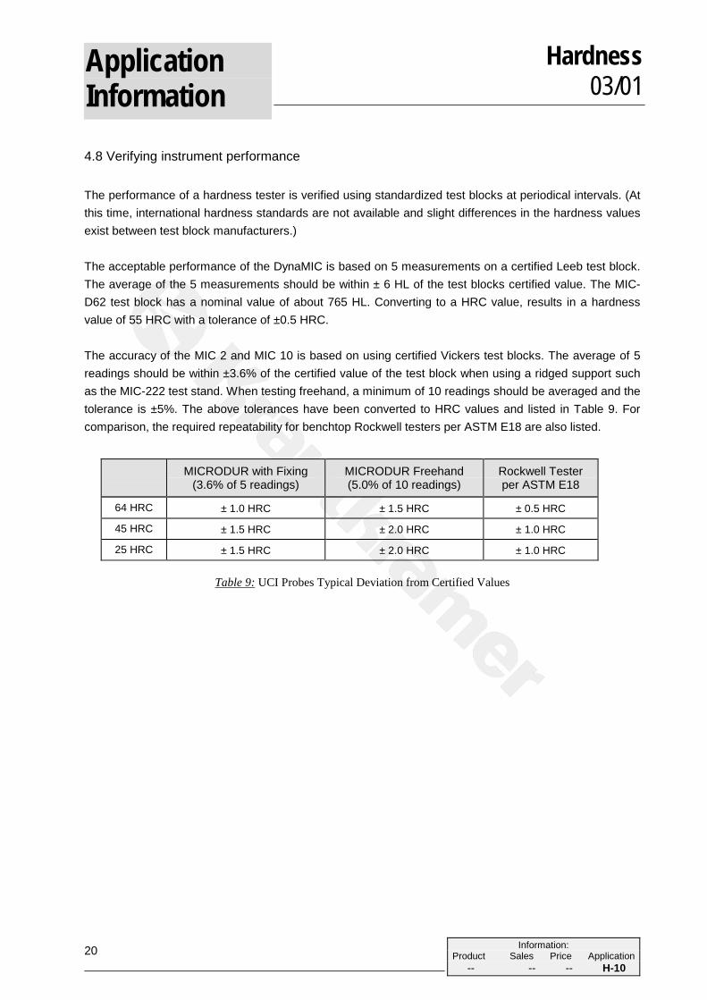
4.8 Verifying instrument performance
The performance of a hardness tester is verified using standardized test blocks at periodical intervals. (Atthis time, international hardness standards are not available and slight differences in the hardness valuesexist between test block manufacturers.)
The acceptable performance of the DynaMIC is based on 5 measurements on a certified Leeb test block.The average of the 5 measurements should be within ± 6 HL of the test blocks certified value. The MIC-D62 test block has a nominal value of about 765 HL. Converting to a HRC value, results in a hardnessvalue of 55 HRC with a tolerance of ±0.5 HRC.
The accuracy of the MIC 2 and MIC 10 is based on using certified Vickers test blocks. The average of 5readings should be within ±3.6% of the certified value of the test block when using a ridged support suchas the MIC-222 test stand. When testing freehand, a minimum of 10 readings should be averaged and thetolerance is ±5%. The above tolerances have been converted to HRC values and listed in Table 9. Forcomparison, the required repeatability for benchtop Rockwell testers per ASTM E18 are also listed.
MICRODUR with Fixing(3.6% of 5 readings)
MICRODUR Freehand(5.0% of 10 readings)
Rockwell Testerper ASTM E18
64 HRC ± 1.0 HRC ± 1.5 HRC ± 0.5 HRC
45 HRC ± 1.5 HRC ± 2.0 HRC ± 1.0 HRC
25 HRC ± 1.5 HRC ± 2.0 HRC ± 1.0 HRC
Table 9: UCI Probes Typical Deviation from Certified Values

21
ApplicationInformation
Hardness03/01
Information:Product Sales Price Application
-- -- -- H-10
5. Solution of the test task
The test task determines whether the UCI method is to be used or the rebound method of hardness test-ing (Table 3). It is not always immediately clear about the most suitable method. Therefore the best an-swer to the testing problem can mostly be given by an experienced sales engineer directly at the test loca-tion.