Embed Size (px)
Citation preview
The author(s) shown below used Federal funds provided by the U.S.Department of Justice and prepared the following final report:
Document Title: Portable Concealed Weapon Detection UsingMillimeter Wave FMCW Radar Imaging
Author(s): Yu-Wen Chang ; Michael Johnson
Document No.: 189918
Date Received: August 30, 2001
Award Number: 1998-DT-CX-K001
This report has not been published by the U.S. Department of Justice.To provide better customer service, NCJRS has made this Federally-funded grant final report available electronically in addition totraditional paper copies.
Opinions or points of view expressed are thoseof the author(s) and do not necessarily reflect
the official position or policies of the U.S.Department of Justice.
Cd I Portable Concealed Weapon Detection Using Millimeter Wave FMCW Radar Imaging
FINAL REPORT
PERlOD OF PERFORMANCE: (February 10,1998 through August 3 1,2000)
NATIONAL INSTITUTE OF JUSTICE OFFICE OF SCIENCE AND TECHNOLOGY
Gk4NT NO, 98-DT-CX-KO01
Date: 1 August 2001
PROPERTY OF Notional Criminal Justice Reference Service (NCJRS) Box 6000 Rockviile, MD 20849-6000
Principal Investigator:Dr. Yu-Wen Chang Principal Engineer: Michael Johnson
CHANG Industry h c . 1925 McKinley Ave. Suite F, La Verne, CA 91750 -
Tel: (909) 596-7888 Fax: (909) 596-8388
This document is a research report submitted to the U.S. Department of Justice. This report has not been published by the Department. Opinions or points of view expressed are those of the author(s) and do not necessarily reflect the official position or policies of the U.S. Department of Justice.
Portable Concealed Weapon Detection Using Millimeter Wave Fh4CW Radar Imaging
TABLE OF CONTENTS
SECTION NUMBER
1 .O ABSTRACT
2.0 INTRODUCTION
3.0 SYSTEM DESCRIPTION 3.1 94 GHz Radar System 3.2 Gimbaled Fast Scan Antenna System 3.3 Data Acquisition 3.4 Hand Held Operation
4.0 DATA ANALYSIS 4.1 FMCW Radar Waveform Processing 4.2 3D Feature Extraction 4.3 Image Processing 4.4 Selected Data
5.0 SAFETY IMPACT CALCULATION 0 - 6.0 CONCLUSIONS AND RECOMMANDATIONS
7.0 ACKNOWLEDGEMENT
8.0 REFERENCE
PAGE NUMBER
i
2
4 5 6 8
11
12 13 14 16 18
23
24
26
27
CHANGIndust~yInc. 98-DT-CX-KO0 1 11
This document is a research report submitted to the U.S. Department of Justice. This report has not been published by the Department. Opinions or points of view expressed are those of the author(s) and do not necessarily reflect the official position or policies of the U.S. Department of Justice.
Portable Concealed Weapon Detection Using Millimeter Wave FMCW Radar Imaging
1.0 ABSTRACT
Unobtrusive detection of concealed weapons on persons or in abandoned bags would provide law enforcement a powerful tool to focus resources and increase traffic throughput in high-risk situations. Under a National Institute of Justice, Office of Science and Technology Grant, Number 98-DT-CX-KOO1, we have developed a fast image scanning 94GHz radar system that is suitable for portable operation and remote viewing of radar data. This system includes a novel fast image- scanning antenna that allows for the acquisition of medium resolution three dimensional millimeter wave images of stationary targets with frame times on order of one second. The three-dimensional radar data allows for potential isolation of concealed weapons from body and environmental clutter such as nearby furniture or other people. The radar is an active system different from the millimeter wave passive imaging system that depends on millimeter wave emissiodreflection contrast between the weapon and the bodyklothing. Therefore, the radar returned image data is the same indoor and outdoor. The 94 GHz radar emitted power of approximately 1mW is low and poses no health concerns for operator or targets. The low power operation is still sufficient to penetrate heavy clothing or material. Small system size allows for easy transport and rapid deployment of the system as well as an easy migration path to future hand held systems with a special image scan technique invented by us. A much faster scanning antenna and data acquisition system is deemed feasible for handheld concealed weapon detection as a result of this research.
Keywords: concealed weapon detection, abandoned bag search, millimeter-wave, short-range radar, fast image scan radar, portable radar, full body scan
CHANGIndustry Inc. 98-DT-CX-KO0 1 1
This document is a research report submitted to the U.S. Department of Justice. This report has not been published by the Department. Opinions or points of view expressed are those of the author(s) and do not necessarily reflect the official position or policies of the U.S. Department of Justice.
Portable Concealed Weapon Detection Using Millimeter Wave FMCW Radar Imaging
2.0 INTRODUCTION
The ability to detect a concealed weapon under clothing at a standoff distance of 10 feet and longer can greatly enhance potential threat detection in situations such as crowd control, school safety, airport security and et. al. The detection can be outdoor and/or indoor. The detector can be handheld for portable short-range detection, or fixedhehicle-mounted for scanning a crowd. Because of the clothing, visible detection of a concealed weapon is impossible. Detection with an infrared thermal detector is also not practical because of the very small temperature contrast of a concealed weapon under clothing and especially heavy clothing. Several techniques are currently being investigated under National Institute of Justice contracts: Ultrasound echo detection of concealed weapon through clothing, microwave signal reflection through clothing and body to detect concealed weapon, passive millimeter wave imaging to detect temperature contrast of the concealed weapon with the body through clothing, and the millimeter wave radar (active) imaging through clothing. There was also a concept of using a magnetometer array for ferric metal weapon detection. Each of the above techniques has its advantages and drawbacks. This research project under National Institute of Justice, Office of Science and Technology sponsorship was to investigate an active millimeter wave imaging techniques and technologies that could enable the design of handheld detectors with a fast image scan time frame to detect concealed weapon at a minimum range of 10 feet. Our research results also indicated further work to be conducted in conjunction with the motion of the person, and the potential limitations of the technique.
Active millimeter-wave imaging of subjects for the purpose of non-invasive search has many attractive aspects: it is possible to produce a reasonable small beam with an antenna compatible with portable or handheld use, system performance is not affected by weather or indoor operation, and fast frame times with good signal to noise ratios can be obtained with low power non-destructive radiation. Though such a system has many attractive aspects, millimeter-wave radar images show a marked difference fiom their visible cousins. The signal and image processing challenges arising fiom specular reflection, glint, phase cancellation, and environmental clutter require a good way to gather data in a variety of environments.
CHANG Industry Inc. has developed a portable fast scanning millimeter-wave radar imaging system that will be able to gather data on a variety of subjects in a variety of roles. The system is suitable for tripod mounting and data can be visualized remotely on a laptop or desktop computer system. This form factor allows the system to be deployed as an entry portal scanner, as an abandoned bag scanner, or as a patrol car mounted system. This flexibility will allow the collection of a large amount of data fiom a variety of missions leading to solution of the signal processing problems that will allow a handheld, or a small commercially available system to be produced.
The selection of the 94GHz band was driven by the compatibility of the required antenna size with handheld or small portable operation. Using only a ten-inch antenna it is possible to generate a beam spot size of less than two inches at a ten-foot standoff distance. A spot size of less than one inch is achievable at five feet, which is compatible with abandoned bag search. This spot size yields an image of metallic and possibly non-metallic targets with a reasonable resolution that can be over- sampled for image processing and target identification purposes. By using an active system the image quality is not dependent on “temperature contrast” or the presence of cold sky radiation and alleviates the need for an extremely high sensitivity receiver. Using less than 1 mW of radiated power there is sufficient signal to noise ratio that a fast frame time is possible by scanning a single
CHANGIndustry Inc. 98-DT-CX-KO0 1 2
This document is a research report submitted to the U.S. Department of Justice. This report has not been published by the Department. Opinions or points of view expressed are those of the author(s) and do not necessarily reflect the official position or policies of the U.S. Department of Justice.
Portable Concealed Weapon Detection Using Millimeter Wave FMCW Radar Imaging
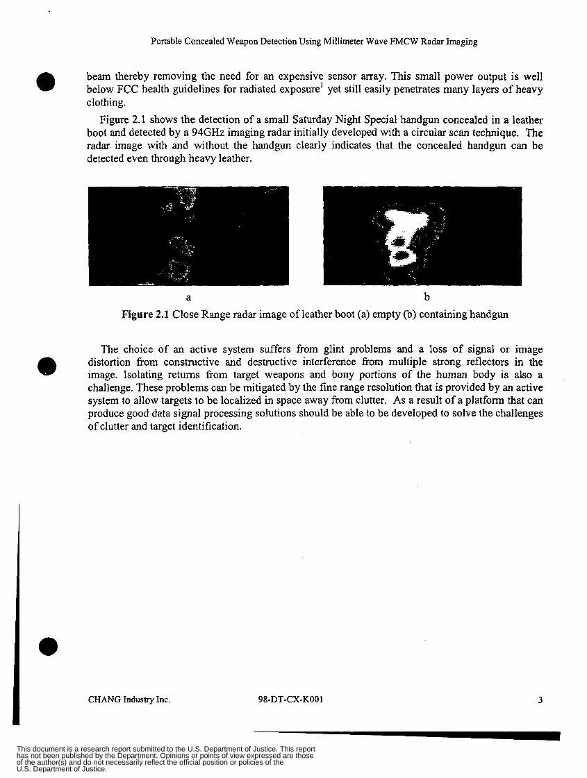
beam thereby removing the need for an expensive sensor array. This small power output is well below FCC health guidelines for radiated exposure’ yet still easily penetrates many layers of heavy clothing.
Figure 2.1 shows the detection of a small Saturday Night Special handgun concealed in a leather boot and detected by a 94GHz imaging radar initially developed with a circular scan technique, The radar. image with and without the handgun clearly indicates that the concealed handgun can be detected even through heavy leather.
0
a
a b Figure 2.1 Close Range radar image of leather boot (a) empty (b) containing handgun
The choice of an active system suffers from glint problems and a loss of signal or image distortion from constructive and destructive interference from multiple strong reflectors in the image. Isolating returns from target weapons and bony portions of the human body is also a challenge. These problems can be mitigated by the fine range resolution that is provided by an active system to allow targets to be localized in space away from clutter. As a result of a platform that can produce good data signal processing solutions should be able to be developed to solve the challenges of clutter and target identification.
CHANG Industry Inc. 98-DT-CX-KO0 1 3
This document is a research report submitted to the U.S. Department of Justice. This report has not been published by the Department. Opinions or points of view expressed are those of the author(s) and do not necessarily reflect the official position or policies of the U.S. Department of Justice.
Portable Concealed Weapon Detection Using Millimeter Wave FMCW Radar Imaging
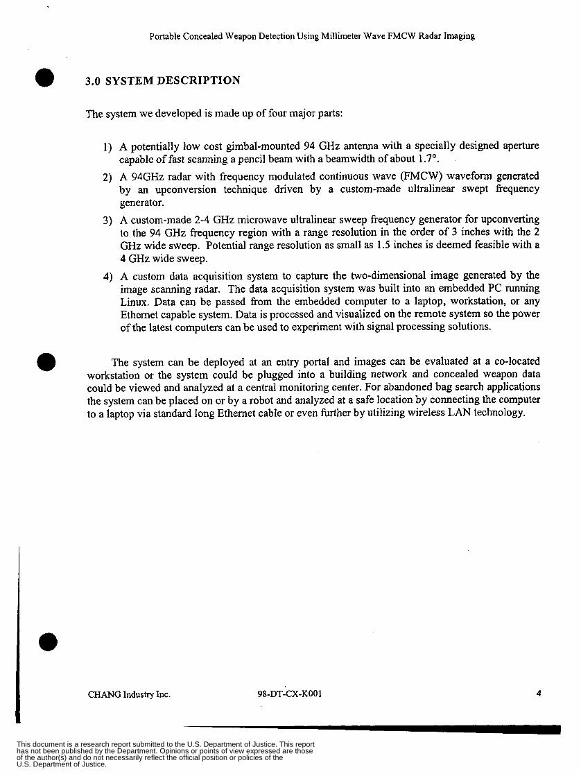
3.0 SYSTEM DESCRIPTION
The system we developed is made up of four major parts:
1) A potentially low cost gimbal-mounted 94 GHz antenna with a specially designed aperture capable of fast scanning a pencil beam with a beamwidth of about 1.7".
2) A 94GHz radar with frequency modulated continuous wave (FMCW) waveform generated by an upconversion technique driven by a custom-made ultralinear swept frequency generator.
3) A custom-made 2-4 GHz microwave ultralinear sweep frequency generator for upconverting to the 94 GHz frequency region with a range resolution in the order of 3 inches with the 2 GHz wide sweep. Potential range resolution as small as 1.5 inches is deemed feasible with a 4 GHz wide sweep.
4) A custom data acquisition system to capture the two-dimensional image generated by the image scanning radar. The data acquisition system was built into an embedded PC running Linux. Data can be passed from the embedded computer to a laptop, workstation, or any Ethernet capable system. Data is processed and visualized on the remote system so the power of the latest computers can be used to experiment with signal processing solutions.
The system can be deployed at an entry portal and images can be evaluated at a co-located workstation or the system could be plugged into a building network and concealed weapon data could be viewed and analyzed at a central monitoring center. For abandoned bag search applications the system can be placed on or by a robot and analyzed at a safe location by connecting the computer to a laptop via standard long Ethernet cable or even hrther by utilizing wireless LAN technology.
CHANG Industry Inc. 98-DT-CX-KO01 4
This document is a research report submitted to the U.S. Department of Justice. This report has not been published by the Department. Opinions or points of view expressed are those of the author(s) and do not necessarily reflect the official position or policies of the U.S. Department of Justice.
Portable Concealed Weapon Detection Using Millimeter Wave FMCW Radar Imaging
Sweep Bandwidth (SBW)
Sweep Period (7,)
3.1 94GHz Radar System.
2GHz
12.6pS
2-4Gl-l~ vco
Number of Samples
Linear
256
1 I 91 GHz Gunn Oscillator
f l Acquisition system
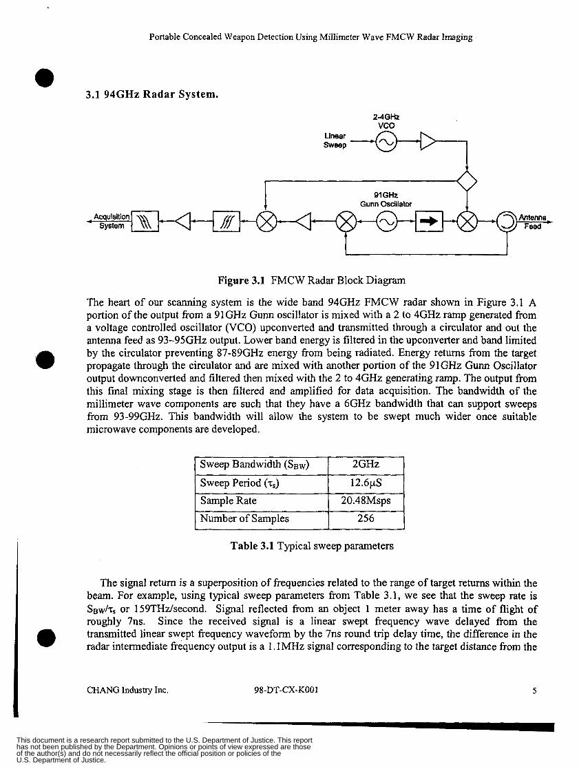
Figure 3.1 FMCW Radar Block Diagram
The heart of our scanning system is the wide band 94GHz FMCW radar shown in Figure 3.1 A portion of the output from a 91GHz Gunn oscillator is mixed with a 2 to 4GHz ramp generated from a voltage controlled oscillator (VCO) upconverted and transmitted through a circulator and out the antenna feed as 93-95GHz output. Lower band energy is filtered in the upconverter and band limited by the circulator preventing 87-89GHz energy from being radiated. Energy returns from the target propagate through the circulator and are mixed with another portion of the 91GHz Gunn Oscillator output downconverted and filtered then mixed with the 2 to 4GHz generating ramp. The output from this final mixing stage is then filtered and amplified for data acquisition. The bandwidth of the millimeter wave components are such that they have a 6GHz bandwidth that can support sweeps from 93-99GHz. This bandwidth will allow the system to be swept much wider once suitable microwave components are developed.
I
Sample Rate 1 20.48Msps
Table 3.1 Typical sweep parameters
e
The signal return is a superposition of frequencies related to the range of target returns within the beam. For example, using typical sweep parameters from Table 3.1, we see that the sweep rate is SB&, or 159THdsecond. Signal reflected from an object 1 meter away has a time of flight of roughly 7ns. Since the received signal is a linear swept frequency wave delayed from the transmitted linear swept frequency waveform by the 7ns round trip delay time, the difference in the radar intermediate frequency output is a 1.1 MHz signal corresponding to the target distance from the
CHANG Industry Inc. 98-DT-CX-KO01 5
This document is a research report submitted to the U.S. Department of Justice. This report has not been published by the Department. Opinions or points of view expressed are those of the author(s) and do not necessarily reflect the official position or policies of the U.S. Department of Justice.
Portable Concealed Weapon Detection Using Millimeter Wave FMCW Radar Imaging
radar. We would like to investigate a wider sweep of 4 GHz or wider to produce 1.5 inch or even 1 inch range resolution. This fast sweep rate places the signals of interest in the 1-5MHz range which is more easily filtered from the near carrier l/f noise and is still low enough to be easily acquired by modem analog to digital converters.
To generate target return signals with very sharp frequency characteristics and hence accurate range information, it is necessary to have a very linear frequency sweep to drive the system. Frequency generating technologies that produce very linear frequency responses are available such as YIG oscillators and phase locked systems. However, none of these can generate a sweep at the speeds necessary for an imaging-radar of this type. A standard VCO (Voltage Controlled Oscillator) was used and the ramp used to modulate the VCO is modified to produce a linear frequency response at the output. This waveform is generated initially by checking the frequency response of the VCO with laboratory test equipments and then optimizing the driving waveform by sharpening the signal return from a known target with the adjustment of the voltage driving waveform while the VCO is in the system. This technique is quite successful and consistently has produced good results. In a fielded system a way to recalibrate the system in the field may still be required. Some work to develop techniques analyze recalibration requirements to allow in system field calibration were performed.
The current system yields a range resolution of roughly 3 inches.
3.2 Gimbaled Fast Scan Antenna System.
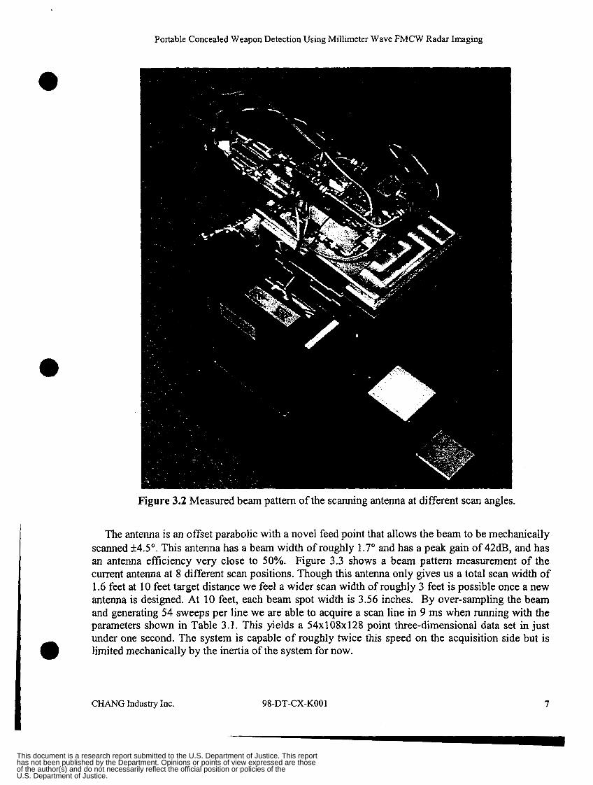
The radar is mounted on a two-axis gimbal system that allows the system to be coarsely aimed at a target or subject. Currently the operator accomplishes course aiming manually. In the fbture a collocated video camera and some simple image processing could automatically aim the system. The system utilizes a fast horizontal line scan generated by our fast scanning antenna and a slow vertical scan generated by the gimbal to scan images. Figure 3.2 is a photo of the development system consisting of the FMCW radar, acquisition system and embedded control solution mounted on a two-axis gimbal.
CHANGIndustryInc. 98-DT-CX-KO0 1 6
This document is a research report submitted to the U.S. Department of Justice. This report has not been published by the Department. Opinions or points of view expressed are those of the author(s) and do not necessarily reflect the official position or policies of the U.S. Department of Justice.
Portable Concealed Weapon Detection Using Millimeter Wave FMCW Radar Imaging
Figure 3.2 Measured beam pattern of the scanning antenna at different scan angles.
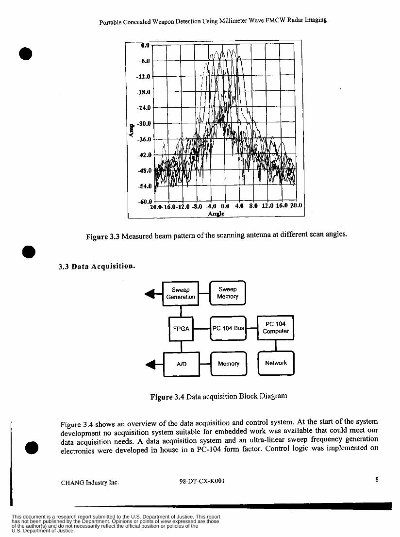
The antenna is an offset parabolic with a novel feed point that allows the beam to be mechanically scanned k4.5". This antenna has a beam width of roughly 1.7" and has a peak gain of 42dB, and has an antenna efficiency very close to 50%. Figure 3.3 shows a beam pattern measurement of the current antenna at 8 different scan positions. Though this antenna only gives us a total scan width of 1.6 feet at 10 feet target distance we feel a wider scan width of roughly 3 feet is possible once a new antenna is designed. At 10 feet, each beam spot width is 3.56 inches. By over-sampling the beam and generating 54 sweeps per line we are able to acquire a scan line in 9 ms when running with the parameters shown in Table 3.1. This yields a 54x108~128 point three-dimensional data set in just under one second. The system is capable of roughly twice this speed on the acquisition side but is limited mechanically by the inertia of the system for now. 0
CHANG Industry Inc. 98-DT-CX-KO0 1 7
This document is a research report submitted to the U.S. Department of Justice. This report has not been published by the Department. Opinions or points of view expressed are those of the author(s) and do not necessarily reflect the official position or policies of the U.S. Department of Justice.
Portable Concealed Weapon Detection Using Millimeter Wave FMCW Radar Imaging
Sweep Generation
- Sweep Memory
Figure 3.3 Measured beam pattern of the scanning antenna at different scan angles.
t 5
pc lo4 Bus - FPGA \ r
3.3 Data Acquisition.
PC 104 Computer
AID - Memory Network
Figure 3.4 Data acquisition Block Diagram
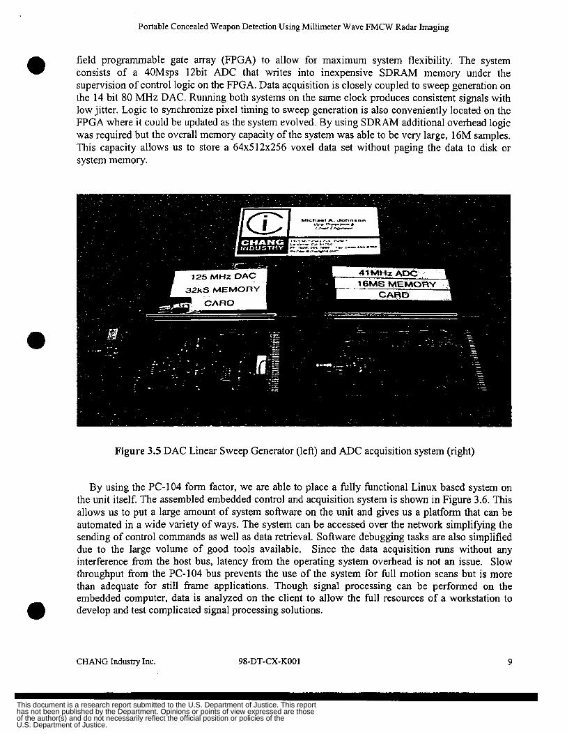
Figure 3.4 shows an overview of the data acquisition and control system. At the start of the system development no acquisition system suitable for embedded work was available that could meet our data acquisition needs. A data acquisition system and an ultra-linear sweep frequency generation electronics were developed in house in a PC-104 form factor. Control logic was implemented on
98-DT-CX-KO01 8 CHANG Industry Inc.
This document is a research report submitted to the U.S. Department of Justice. This report has not been published by the Department. Opinions or points of view expressed are those of the author(s) and do not necessarily reflect the official position or policies of the U.S. Department of Justice.
Portable Concealed Weapon Detection Using Millimeter Wave FMCW Radar Imaging
field programmable gate array (FPGA) to allow for maximum system flexibility. The system consists of a 40Msps 12bit ADC that writes into inexpensive SDRAM memory under the supervision of control logic on the FPGA. Data acquisition is closely coupled to sweep generation on the 14 bit 80 MHz DAC. Running both systems on the same clock produces consistent signals with low jitter. Logic to synchronize pixel timing to sweep generation is also conveniently located on the FPGA where it could be updated as the system evolved. By using SDRAM additional overhead logic was required but the overall memory capacity of the system was able to be very large, 16M samples. This capacity allows us to store a 64x512~256 voxel data set without paging the data to disk or system memory.
0
Figure 3.5 DAC Linear Sweep Generator (left) and ADC acquisition system (right)
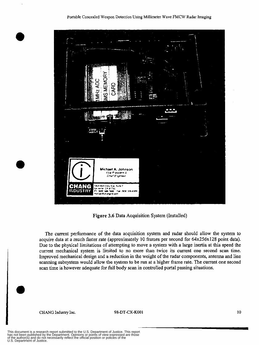
By using the PC-104 form factor, we are able to place a fully functional Linux based system on the unit itself. The assembled embedded control and acquisition system is shown in Figure 3.6. This allows us to put a large amount of system software on the unit and gives us a platform that can be automated in a wide variety of ways. The system can be accessed over the network simplifying the sending of control commands as well as data retrieval. Software debugging tasks are also simplified due to the large volume of good tools available. Since the data acquisition runs without any interference from the host bus, latency from the operating system overhead is not an issue. Slow throughput from the PC-I04 bus prevents the use of the system for full motion scans but is more than adequate for still frame applications. Though signal processing can be performed on the embedded computer, data is analyzed on the client to allow the full resources of a workstation to develop and test complicated signal processing solutions. 0
CHANG Industrylnc. 98-DT-CX-KO01 9
U.S. Department of Justice.of the author(s) and do not necessarily reflect the official position or policies of thehas not been published by the Department. Opinions or points of view expressed are thoseThis document is a research report submitted to the U.S. Department of Justice. This report
Portable Concealed Weapon Detection Using Millimeter Wave FMCW Radar Imaging
Figure 3.6 Data Acquisition System (Installed)
The current performance of the data acquisition system and radar should allow the system to acquire data at a much faster rate (approximately 10 frames per second for 64x256~128 point data). Due to the physical limitations of attempting to move a system with a large inertia at this speed the current mechanical system is limited to no more than twice its current one second scan time. Improved mechanical design and a reduction in the weight of the radar components, antenna and line scanning subsystem would allow the system to be run at a higher fiame rate. The current one second scan time is however adequate for full body scan in controlled portal passing situations.
CHANG Industry Inc. 98-DT-CX-KO01 10
This document is a research report submitted to the U.S. Department of Justice. This report has not been published by the Department. Opinions or points of view expressed are those of the author(s) and do not necessarily reflect the official position or policies of the U.S. Department of Justice.
Portable Concealed Weapon Detection Using Millimeter Wave FMCW Radar Imaging
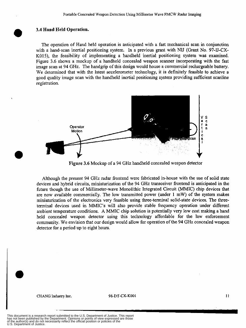
3.4 Hand Held Operation. 0 The operation of Hand held operation is anticipated with a fast mechanical scan in conjunction
with a hand-scan inertial positioning system. In a previous grant with NU (Grant No. 97-IJ-CX- KO1 5) , the feasibility of implementing a handheld inertial positioning system was examined. Figure 3.6 shows a mockup of a handheld concealed weapon scanner incorporating with the fast image scan at 94 GHz. The handgrip of this design would house a commercial rechargeable battery. We determined that with the latest accelerometer technology, it is definitely feasible to achieve a good quality image scan with the handheld inertial positioning system providing sufficient scanline registration.
Figure 3.6 Mockup of a 94 GHz handheld concealed weapon detector
Although the present 94 GHz radar frontend were fabricated in-house with the use of solid state devices and hybrid circuits, miniaturization of the 94 GHz transceiver frontend is anticipated in the fbture though the use of Millimeter-wave Monolithic Integrated Circuit (MMIC) chip devices that are now available commercially. The low transmitted power (under 1 mW) of the system makes miniaturization of the electronics very feasible using three-terminal solid-state devices. The three- terminal devices used in MMIC’s will also provide stable frequency operation under different ambient temperature conditions. A MMIC chip solution is potentially very low cost making a hand held concealed weapon detector using this technology affordable for the law enforcement community. We envision that our design would allow for operation of the 94 GHz concealed weapon detector for a period up to eight hours.
CHANG Industry Inc. 98-DT-CX-KO0 1 1 1
This document is a research report submitted to the U.S. Department of Justice. This report has not been published by the Department. Opinions or points of view expressed are those of the author(s) and do not necessarily reflect the official position or policies of the U.S. Department of Justice.
Portable Concealed Weapon Detection Using Millimeter Wave FMCW Radar Imaging
4.0 DATA ANALYSIS
The signal processing challenges consist of three major parts. The first challenge is to process the raw FMCW radar returns, remove noise, system artifacts, and pre-scale data. The second challenge is much larger and consists of processing the data volumes to remove effects of system phenomenology that can obscure the meaning of the data. The third challenge is formatting and presenting the data in such a way that an operator or computer algorithm can better understand and interpret the data.
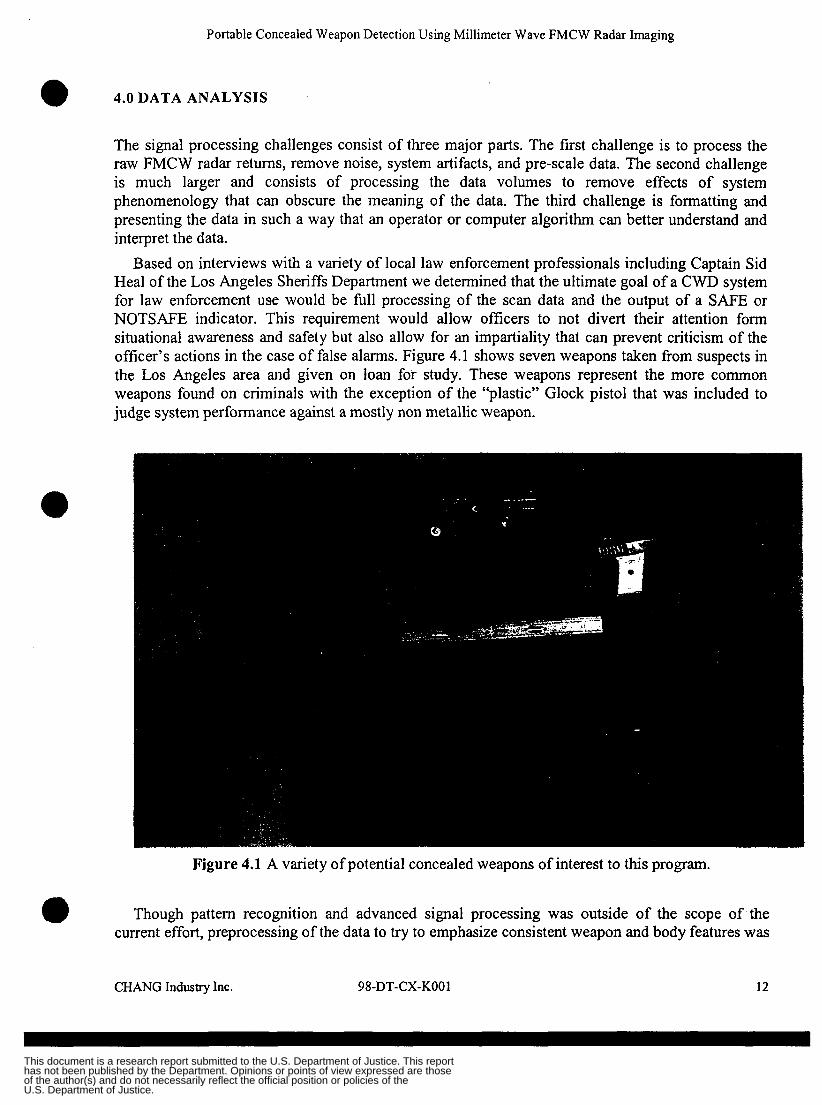
Based on interviews with a variety of local law enforcement professionals including Captain Sid Heal of the Los Angeles Sheriffs Department we determined that the ultimate goal of a CWD system for law enforcement use would be full processing of the scan data and the output of a SAFE or NOTSAFE indicator. This requirement would allow officers to not divert their attention form situational awareness and safety but also allow for an impartiality that can prevent criticism of the officer’s actions in the case of false alarms. Figure 4.1 shows seven weapons taken from suspects in the Los Angeles area and given on loan for study. These weapons represent the more common weapons found on criminals with the exception of the “plastic” Glock pistol that was included to judge system performance against a mostly non metallic weapon.
Figure 4.1 A variety of potential concealed weapons of interest to this program.
Though pattern recognition and advanced signal processing was outside of the scope of the current effort, preprocessing of the data to try to emphasize consistent weapon and body features was
a CHANG Industry Inc. 98-DT-CX-KO0 1 12
This document is a research report submitted to the U.S. Department of Justice. This report has not been published by the Department. Opinions or points of view expressed are those of the author(s) and do not necessarily reflect the official position or policies of the U.S. Department of Justice.
Portable Concealed Weapon Detection Using Millimeter Wave FMCW Radar Imaging
undertaken. In addition since a potential intermediate application of the system would be the scanning of stationary targets, such as abandoned bags, by trained operators some effort to produce recognizable images was performed. Processing of the radar data acquired from the system requires three stages before reduced data sets that could be used for pattern recognition research are required: FMCW Waveform processing, 3D feature extraction and image processing.
0
4.1 FMCW Waveform Radar Processing
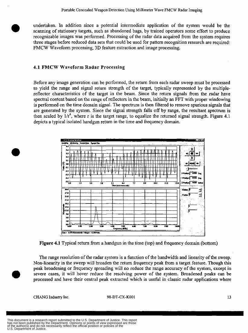
Before any image generation can be performed, the return from each radar sweep must be processed to yield the range and signal return strength of the target, typically represented by the multiple- reflector characteristics of the target in the beam. Since the return signals from the radar have spectral content based on the range of reflectors in the beam, initially an FFT with proper windowing is performed on the time domain signal. The spectrum is then filtered to remove spurious signals that are generated by the system. Since the signal strength falls off by range, the resultant spectrum is then scaled by lh4, where r is the target range, to equalize the returned signal strength. Figure 4.1 depicts a typical isolated handgun return in the time and frequency domain.
Figure 4.1 Typical return from a handgun in the time (top) and frequency domain (bottom)
The range resolution of the radar system is a function of the bandwidth and linearity of the sweep. Non-linearity in the sweep will broaden the return frequency peak from a target feature. Though this peak broadening or frequency spreading will no reduce the range accuracy of the system, except in severe cases, it will hover reduce the resolving power of the system. Broadened peaks can be processed and have their central peak extracted which is useful in classic radar applications where a CHANGIndustry Inc. 98-DT-CX-KO01 13
This document is a research report submitted to the U.S. Department of Justice. This report has not been published by the Department. Opinions or points of view expressed are those of the author(s) and do not necessarily reflect the official position or policies of the U.S. Department of Justice.
Portable Concealed Weapon Detection Using Millimeter Wave FMCW Radar Imaging
target range is of primary interest. In an imaging radar application for purposes of CWD broadened peaks are problematic however as they do no allow closely spaced features to be resolved. CWD applications are characterized by an abundance of clutter reflectors that have radar cross-sections on the same order of magnitude as the target signals.
Due to this need for good range resolution great effort was put into generating an ultra-linear sweep and proving a wide sweep bandwidth. Investigation into peak sharpening routines and ways of characterizing residual sweep non-linearities were also investigated. Ultimately however the best solution is to provide as wide a frequency sweep as possible with the greatest degree of linearity. The radar front end used for test was capable of a 6Ghz sweep but was only swept 2GHz due to the difficulty of producing a multi octave linear sweep as well as the general lack of appropriate wide bandwidth high performance IF components.
0
4.2 3D Feature Extraction
Due to the three dimensional nature of the datasets produced by the imaging FMCW radar system it is possible to isolate target returns based not only by position in the frame but also by range from the radar. Imaging sensors must first remove background clutter from an image to isolate the target being scanned and prevent recognition algorithms from having to ignore background clutter. In an imaging sensor system that does not provide range information this can be a daunting task in of itself. The FMCW radar return datasets however produce full three dimensional data sets which can easily remove background and foreground clutter. In a simplified example Figure 4.2 shows a radar return dataset overlaid onto a computer model of the physical setup it had scanned. 0
C H U G Industry Inc. 98-DT-CX-KO01 14
This document is a research report submitted to the U.S. Department of Justice. This report has not been published by the Department. Opinions or points of view expressed are those of the author(s) and do not necessarily reflect the official position or policies of the U.S. Department of Justice.
Portable Concealed Weapon Detection Using Millimeter Wave FMCW Radar Imaging
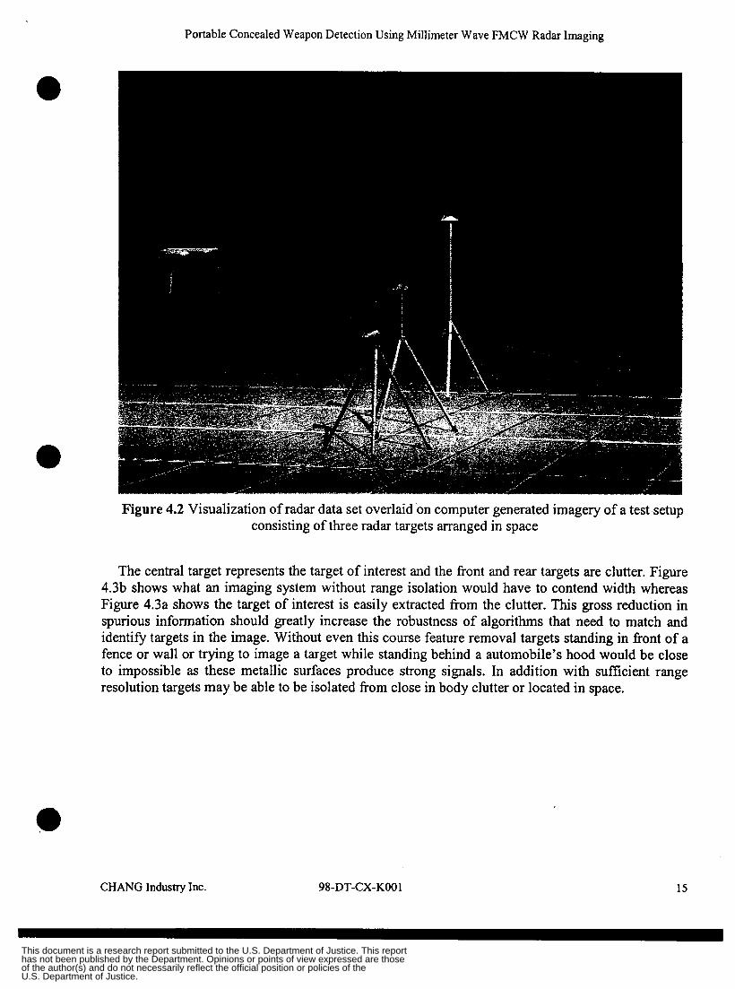
Figure 4.2 Visualization of radar data set overlaid on computer generated imagery of a test setup consisting of three radar targets arranged in space
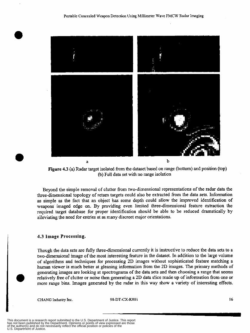
The central target represents the target of interest and the front and rear targets are clutter. Figure 4.3b shows what an imaging system without range isolation would have to contend width whereas Figure 4.3a shows the target of interest is easily extracted from the clutter. This gross reduction in spurious information should greatly increase the robustness of algorithms that need to match and identify targets in the image. Without even this course feature removal targets standing in front of a fence or wall or trying to image a target while standing behind a automobile’s hood would be close to impossible as these metallic surfaces produce strong signals. In addition with sufficient range resolution targets may be able to be isolated from close in body clutter or located in space.
CHANG Industry Inc. 98-DT-CX-KO0 1 15
This document is a research report submitted to the U.S. Department of Justice. This report has not been published by the Department. Opinions or points of view expressed are those of the author(s) and do not necessarily reflect the official position or policies of the U.S. Department of Justice.
Portable Concealed Weapon Detection Using Millimeter Wave FMCW Radar Imaging
a b Figure 4.3 (a) Radar target isolated from the dataset based on range (bottom) and position (top)
(b) Full data set with no range isolation
Beyond the simple removal of clutter from two-dimensional representations of the radar data the three-dimensional topology of return targets could also be extracted from the data sets. Information as simple as the fact that an object has some depth could allow the improved identification of weapons imaged edge on. By providing even limited three-dimensional feature extraction the required target database for proper identification should be able to be reduced dramatically by alleviating the need for entries at as many discreet major orientations.
4.3 Image Processing.
Though the data sets are fdly three-dimensional currently it is instructive to reduce the data sets to a two-dimensional image of the most interesting feature in the dataset. In addition to the large volume of algorithms and techniques for processing 2D images without sophisticated feature matching a human viewer is much better at gleaning information from the 2D images. The primary methods of generating images are looking at spectrograms of the data sets and then choosing a range that seems relatively fiee of clutter or noise then generating a 2D data slice made up of information from one or more range bins. Images generated by the radar in this way show a variety of interesting effects.
CHANG Industry Inc. 98-DT-CX-KO01 16
This document is a research report submitted to the U.S. Department of Justice. This report has not been published by the Department. Opinions or points of view expressed are those of the author(s) and do not necessarily reflect the official position or policies of the U.S. Department of Justice.
Portable Concealed Weapon Detection Using Millimeter Wave FMCW Radar Imaging
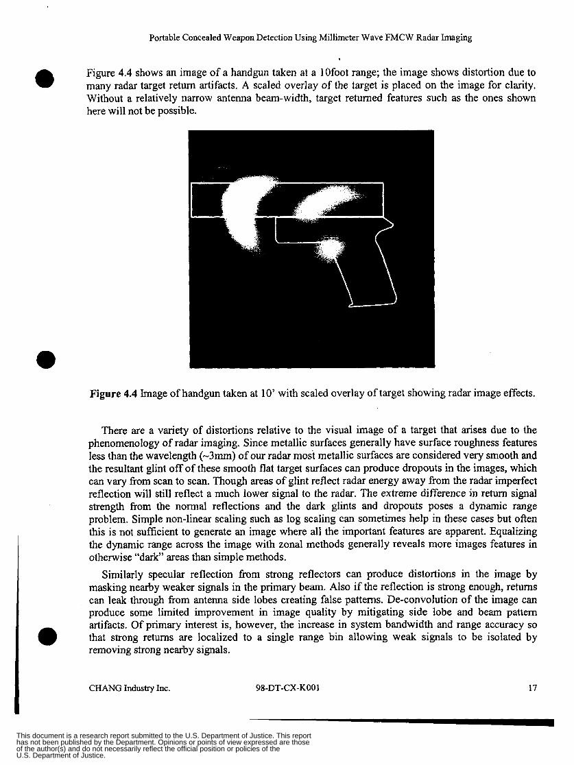
Figure 4.4 shows an image of a handgun taken at a lOfoot range; the image shows distortion due to many radar target return artifacts. A scaled overlay of the target is placed on the image for clarity. Without a relatively narrow antenna beam-width, target returned features such as the ones shown here will not be possible.
Figure 4.4 Image of handgun taken at 10’ with scaled overlay of target showing radar image effects.
There are a variety of distortions relative to the visual image of a target that arises due to the phenomenology of radar imaging. Since metallic surfaces generally have surface roughness features less than the wavelength (-3mm) of our radar most metallic surfaces are considered very smooth and the resultant glint off of these smooth flat target surfaces can produce dropouts in the images, which can vary fi-om scan to scan. Though areas of glint reflect radar energy away from the radar imperfect reflection will still reflect a much lower signal to the radar. The extreme difference in return signal strength from the normal reflections and the dark glints and dropouts poses a dynamic range problem. Simple non-linear scaling such as log scaling can sometimes help in these cases but often this is not sufficient to generate an image where all the important features are apparent. Equalizing the dynamic range across the image with zonal methods generally reveals more images features in otherwise “dark” areas than simple methods.
Similarly specular reflection from strong reflectors can produce distortions in the image by masking nearby weaker signals in the primary beam. Also if the reflection is strong enough, returns can leak through from antenna side lobes creating false patterns. De-convolution of the image can produce some limited improvement in image quality by mitigating side lobe and beam pattern artifacts. Of primary interest is, however, the increase in system bandwidth and range accuracy so that strong returns are localized to a single range bin allowing weak signals to be isolated by removing strong nearby signals.
CHANG Industry Inc. 98-DT-CX-KO0 1 17
This document is a research report submitted to the U.S. Department of Justice. This report has not been published by the Department. Opinions or points of view expressed are those of the author(s) and do not necessarily reflect the official position or policies of the U.S. Department of Justice.
Portable Concealed Weapon Detection Using Millimeter Wave FMCW Radar Imaging
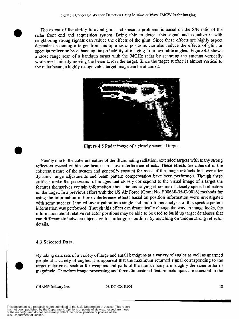
The extent of the ability to avoid glint and specular problems is based on the S/N ratio of the radar front end and acquisition system. Being able to detect this signal and equalize it with neighboring strong signals can reduce the effects of the glint. Since these effects are highly aspect dependent scanning a target from multiple radar positions can also reduce the effects of glint or specular reflection by enhancing the probability of imaging from favorable angles. Figure 4.5 shows a close range scan of a handgun target with the 94GHz radar by scanning the antenna vertically while mechanically moving the beam across the target. Since the target surface is almost vertical to the radar beam, a highly recognizable target image can be obtained.
Figure 4.5 Radar image of a closely scanned target.
Finally due to the coherent nature of the illuminating radiation, extended targets with many strong reflectors spaced within one beam can show interference effects. These effects are inherent in the coherent nature of the system and generally account for most of the image artifacts left over after dynamic range adjustments and beam pattern compensation have been performed. Though these artifacts make the generation of images that closely correspond to the visual image of a target the features themselves contain infomation about the underlying structure of closely spaced reflectors on the target. In a previous effort with the US Air Force (Grant No. F08630-95-C-0018) methods for using the information in these interference effects based on position information were investigated with some success. Limited investigation into single and multi kame analysis of this speckle pattern information was performed. Though this effect can dramatically change the way an image looks, the information about relative reflector positions may be able to be used to build up target databases that can differentiate between objects with similar gross outlines by matching on unique strong reflector details.
4.3 Selected Data.
By taking data sets of a variety of large and small handguns at a variety of angles as well as unarmed people at a variety of angles, it is apparent that the maximum returned signal corresponding to the target radar cross section for weapons and parts of the human body are roughly the same order of magnitude. Therefore image processing and three dimensional feature techniques are essential to the
CHANGIndustryInc. 98-DT-CX-KO01 18
This document is a research report submitted to the U.S. Department of Justice. This report has not been published by the Department. Opinions or points of view expressed are those of the author(s) and do not necessarily reflect the official position or policies of the U.S. Department of Justice.
Portable Concealed Weapon Detection Using Millimeter Wave FMCW Radar Imaging
Target
#1 Glock #3 Colt #4 Raven #6 Davis #7 Beretta #8 Colt #9 Ruger
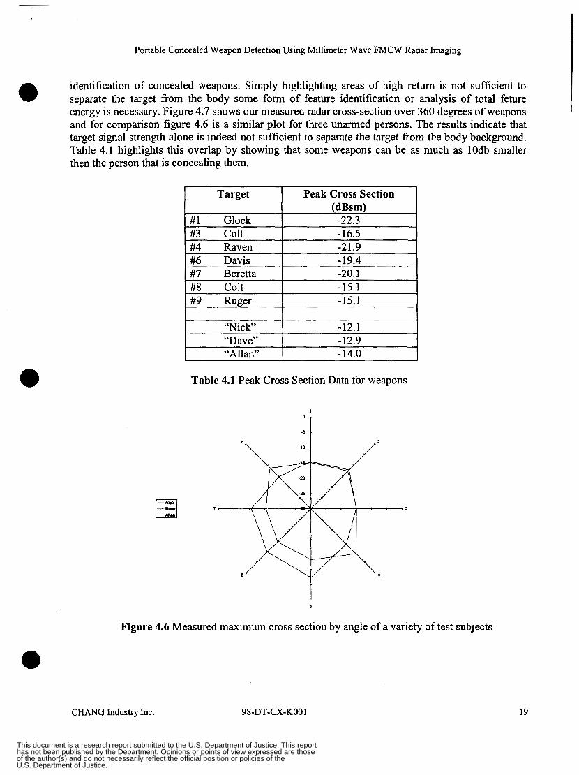
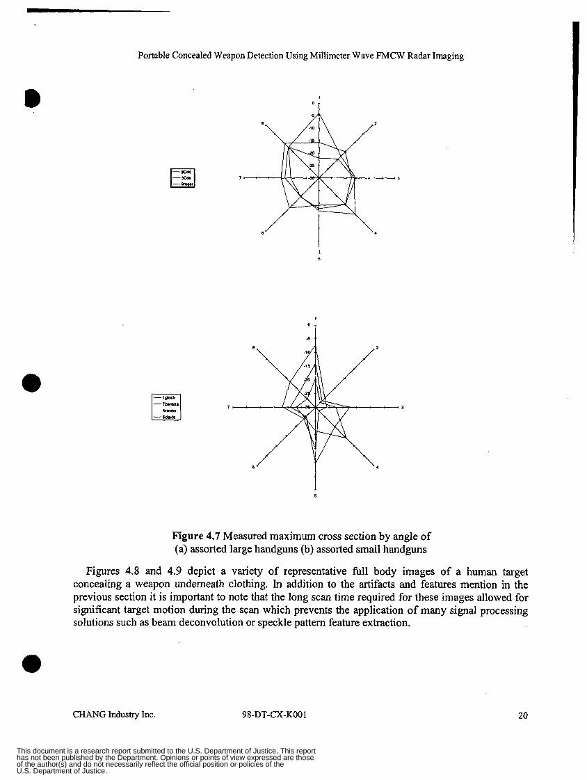
identification of concealed weapons. Simply highlighting areas of high return is not sufficient to separate the target from the body some form of feature identification or analysis of total feture energy is necessary. Figure 4.7 shows our measured radar cross-section over 360 degrees of weapons and for comparison figure 4.6 is a similar plot for three unarmed persons. The results indicate that target signal strength alone is indeed not sufficient to separate the target from the body background. Table 4.1 highlights this overlap by showing that some weapons can be as much as lOdb smaller then the person that is concealing them.
Peak Cross Section (dBsm) -22.3 -16.5 -21.9 -19.4 -20.1 -15.1 -15.1
-12.9
Table 4.1 Peak Cross Section Data for weapons
1
Figure
3
5
4.6 Measured maximum cross section by angle of a variety of test subjects
CHANG Industry Inc. 98-DT-CX-KO0 1 19
This document is a research report submitted to the U.S. Department of Justice. This report has not been published by the Department. Opinions or points of view expressed are those of the author(s) and do not necessarily reflect the official position or policies of the U.S. Department of Justice.
Portable Concealed Weapon Detection Using Millimeter Wave FMCW Radar Imaging
1
7- 3
6
5
Figure 4.7 Measured maximum cross section by angle of (a) assorted large handguns (b) assorted small handguns
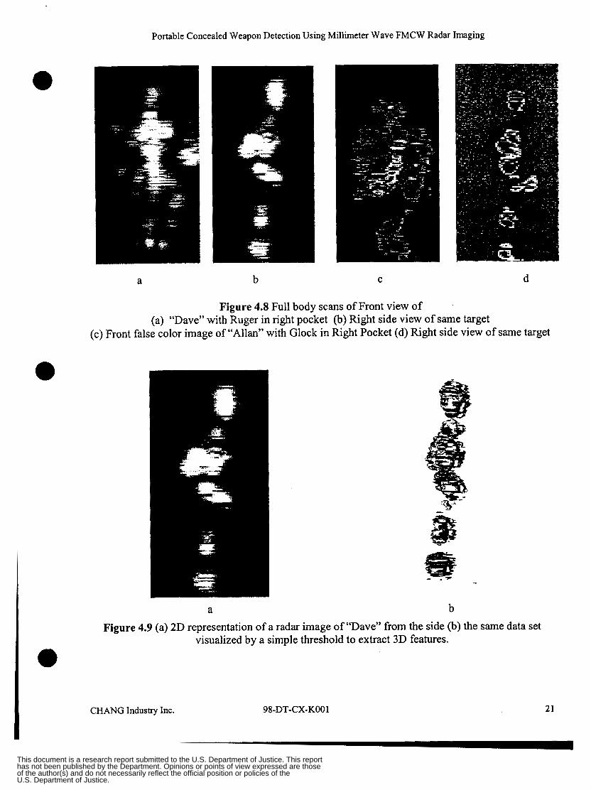
Figures 4.8 and 4.9 depict a variety of representative full body images of a human target concealing a weapon underneath clothing. In addition to the artifacts and features mention in the previous section it is important to note that the long scan time required for these images allowed for significant target motion during the scan which prevents the application of many signal processing solutions such as beam deconvolution or speckle pattern feature extraction.
CHANGIndustry Jnc. 98-DT-CX-KO01 20
This document is a research report submitted to the U.S. Department of Justice. This report has not been published by the Department. Opinions or points of view expressed are those of the author(s) and do not necessarily reflect the official position or policies of the U.S. Department of Justice.
Portable Concealed Weapon Detection Using Millimeter Wave FMCW Radar Imaging
a b C d
Figure 4.8 Full body scans of Front view of (a) “Dave” with Ruger in right pocket (b) Right side view of same target
(c) Front false color image of “Allan” with Glock in Right Pocket (d) Right side view of same target
b a Figure 4.9 (a) 2D representation of a radar image of “Dave” from the side (b) the same data set
visualized by a simple threshold to extract 3D features.
21 CHANG Industry Inc. 98-DT-CX-KO0 1
This document is a research report submitted to the U.S. Department of Justice. This report has not been published by the Department. Opinions or points of view expressed are those of the author(s) and do not necessarily reflect the official position or policies of the U.S. Department of Justice.
Portable Concealed Weapon Detection Using Millimeter Wave FMCW Radar Imaging
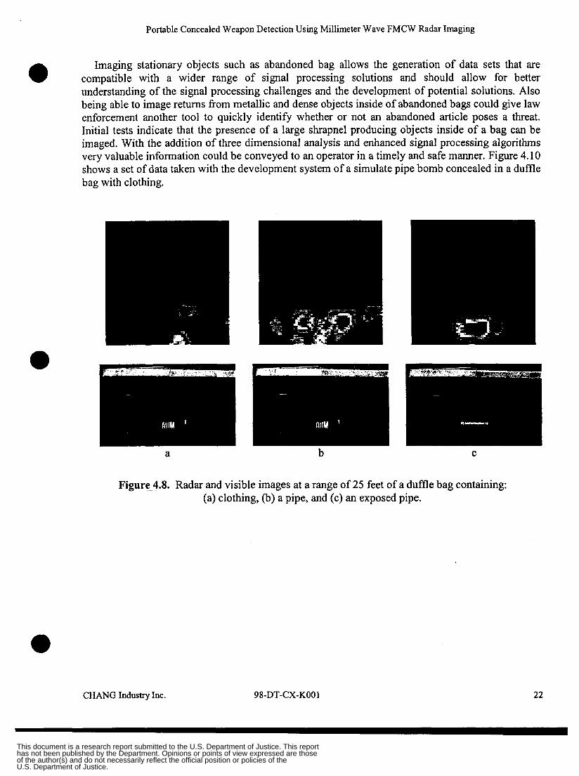
Imaging stationary objects such as abandoned bag allows the generation of data sets that are compatible with a wider range of signal processing solutions and should allow for better understanding of the signal processing challenges and the development of potential solutions. Also being able to image returns from metallic and dense objects inside of abandoned bags could give law enforcement another tool to quickly identify whether or not an abandoned article poses a threat. Initial tests indicate that the presence of a large shrapnel producing objects inside of a bag can be imaged. With the addition of three dimensional analysis and enhanced signal processing algorithms very valuable information could be conveyed to an operator in a timely and safe manner. Figure 4.10 shows a set of data taken with the development system of a simulate pipe bomb concealed in a duffle bag with clothing.
0
a b C
Figure-4.8. Radar and visible images at a range of 25 feet of a duffle bag containing: (a) clothing, (b) a pipe, and (c) an exposed pipe.
CHANG Industry Inc. 98-DT-CX-KO0 1 22
This document is a research report submitted to the U.S. Department of Justice. This report has not been published by the Department. Opinions or points of view expressed are those of the author(s) and do not necessarily reflect the official position or policies of the U.S. Department of Justice.
Portable Concealed Weapon Detection Using Millimeter Wave FMCW Radar Imaging
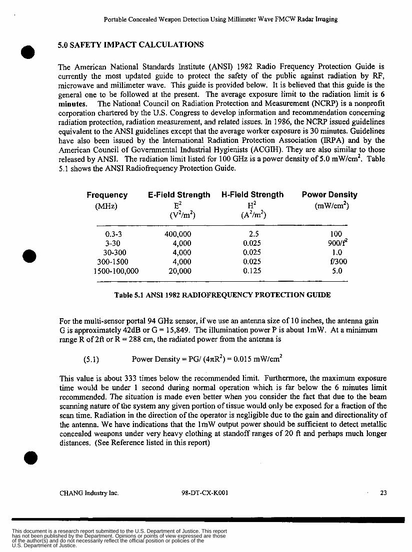
5.0 SAFETY IMPACT CALCULATIONS 0 The American National Standards Institute (ANSI) 1982 Radio Frequency Protection Guide is currently the most updated guide to protect the safety of the public against radiation by RF, microwave and millimeter wave. This guide is provided below. It is believed that this guide is the general one to be followed at the present. The average exposure limit to the radiation limit is 6 minutes. The National Council on Radiation Protection and Measurement (NCRP) is a nonprofit corporation chartered by the U.S. Congress to develop information and recommendation concerning radiation protection, radiation measurement, and related issues. In 1986, the NCRP issued guidelines equivalent to the ANSI guidelines except that the average worker exposure is 30 minutes. Guidelines have also been issued by the International Radiation Protection Association (IRPA) and by the American Council of Governmental Industrial Hygienists (ACGM). They are also similar to those released by ANSI. The radiation limit listed for 100 GHz is a power density of 5.0 mW/cm2. Table 5.1 shows the ANSI Radiofkequency Protection Guide.
Frequency E-Field Strength H-Field Strength Power Density (MHd E2 H2 (mW/cm2)
(V2/m2) ( A2/m2)
0.3-3 400,000 2.5 3-30 4,000 0.025
30-300 4,000 0.025 300- 1 500 4,000 0.025
1500-1 00,000 20,000 0.125
100
1 .o €7300 5.0
9oo/e
Table 5.1 ANSI 1982 RADIOFREQUENCY PROTECTION GUIDE
For the multi-sensor portal 94 GHz sensor, if we use an antenna size of 10 inches, the antenna gain G is approximately 42dB or G = 15,849. The illumination power P is about 1mW. At a minimum range R of 2ft or R = 288 cm, the radiated power from the antenna is
(5.1) Power Density = PG/ (4nR2) = 0.01 5 mW/cm2
This value is about 333 times below the recommended limit. Furthermore, the maximum exposure time would be under 1 second during normal operation which is far below the 6 minutes limit recommended. The situation is made even better when you consider the fact that due to the beam scanning nature of the system any given portion of tissue would only be exposed for a fiaction of the scan time. Radiation in the direction of the operator is negligible due to the gain and directionality of the antenna. We have indications that the 1mW output power should be sufficient to detect metallic concealed weapons under very heavy clothing at standoff ranges of 20 ft and perhaps much longer distances. (See Reference listed in this report)
CHANG IndustryInc. 98-DT-CX-KO0 1 ' 23
This document is a research report submitted to the U.S. Department of Justice. This report has not been published by the Department. Opinions or points of view expressed are those of the author(s) and do not necessarily reflect the official position or policies of the U.S. Department of Justice.
Portable Concealed Weapon Detection Using Millimeter Wave FMCW Radar Imaging
6.0 CONCLUSIONS AND RECOMMANDATIONS.
Even though active radar images of concealed weapons have some drawbacks such as glint and specular reflection or artifacts such as coherent interference these problems should be able to be overcome or used to our advantage once enough data is available to tackle the problem fully. In addition to building up a library of data on radar returns from body parts nearby clutter targets can already be isolated by range resolution that could be increased by another 50%, the concealing clothing itself can reduce glint and specular reflections, and positional jitter and large fiequency shifts show some promise in reducing or making use of interference effects.
Using a millimeter wave 94GHz radar for concealed weapon imaging has the following advantages:
Relatively small antenna size to generate a narrow antenna beam for sharp lateral resolution in a form factor compatible with portable or handheld use. Very small transmitted power at 94GHz making handheld portable detector possible
Very small transmitted power at 94GHz will be cause damage to the human body and eyes Ability to penetrate relatively heavy clothing including leather
Ability to generate consistent images indoors and outdoors independent of weather
Potential low final system cost
Three dimensional data for better target identification
Generates data that is machine decipherable so should not raise privacy concerns
0
0
When compared to food, clothing, shoes etc. shrapnel producing metal objects in abandoned bags should show up easily even at long stand off distances. The potential usefulness for bag search could be great. Since the bag is stationary, by obtaining repeated image scans of the three-dimensional data sets the expert information needed to determine the existence of the pipe bomb could be greatly reduced.
For future active radar imaging concealed weapon detection, the following recommendations are provided for consideration:
Development of faster scan to counter body motion
Development of fast scanning, rugged and light gimbal system
Miniaturization of the 94GHz radar frontend based on low cost MMIC electronics
Collection of a large number of concealed weapon radar signal data through different possible clothing types to establish the data base for target recognition software development Extensive analysis of concealed weapon data sets to produce robust target isolation and identification algorithms.
CHANG Industry Inc. 98-DT-CX-KO0 1 24
This document is a research report submitted to the U.S. Department of Justice. This report has not been published by the Department. Opinions or points of view expressed are those of the author(s) and do not necessarily reflect the official position or policies of the U.S. Department of Justice.
Portable Concealed Weapon Detection Using Millimeter Wave FMCW Radar Imaging
Therefore, we conclude that further development effort is necessary to bring this technology to its maturity and to the law enforcement market place.
CHANG Industry Inc. 98-DT-CX-KO01 25
This document is a research report submitted to the U.S. Department of Justice. This report has not been published by the Department. Opinions or points of view expressed are those of the author(s) and do not necessarily reflect the official position or policies of the U.S. Department of Justice.
Portable Concealed Weapon Detection Using Millimeter Wave FMCW Radar Imaging
7.0 ACKNOWLEDGMENTS
This work was sponsored by the National Institute of Justice under contract 98-DT-CX-K001. Background work was also performed under NU contract 97-U-CX-KOlS. The authors would like to thank Mr. Dave Ferris and Mr. Nicholas Cume for all of the insightful discussions and help with data collection. We would also like to thank Dr. Pete Nacci (program manager) and Mr. David Beaupre as well as Mr. Irv Smietan (former program manager), Ms. Jodi Tumer, and for all of the contract support help. Finally we would like to thank Lt. Sid Heal and the Los Angeles County Sheriffs Department for supplying handgun targets and a healthy dose of the real world.
PROPERTY OF National Criminal Justice Reference Service (NCJRS) Box 6000 Rockville, MD 20849-6000 -,/- - I
CHANGIndustryInc. 98-DT-CX-KO01 26
This document is a research report submitted to the U.S. Department of Justice. This report has not been published by the Department. Opinions or points of view expressed are those of the author(s) and do not necessarily reflect the official position or policies of the U.S. Department of Justice.
Portable Concealed Weapon Detection Using Millimeter Wave FMCW Radar Imaging
0 8.0 REFERENCE
I . FCC OET Bulletin No. 56, Questions and Answers About the Biological Effects and Potential Hazards of Radiofrequency Electromagnetic Fields.
98-DT-CX-KO01 27 CHANG Industry Inc.
This document is a research report submitted to the U.S. Department of Justice. This report has not been published by the Department. Opinions or points of view expressed are those of the author(s) and do not necessarily reflect the official position or policies of the U.S. Department of Justice.

![3D Holographic Millimeter-Wave Imaging for Concealed Metallic … · 2018. 6. 27. · Various imaging techniques include infrared imaging [ 5, 6], passive millimeter-wave (MMW) imaging](https://img.pdfslide.us/doc/110x75/60cad3ad9597fd36557ea88e/3d-holographic-millimeter-wave-imaging-for-concealed-metallic-2018-6-27-various.jpg)