Embed Size (px)
Citation preview
1
Concealed Weapon Detection Using Terahertz Technology
Report on Winter Project
By
Ramit Mukherjee, Krishnendu Chakraborty, Anik Batabyal,
Jayanta Das and Subham Kr. Bhagat
Department of Electronics and Telecommunication Engineering
IIEST, Shibpur
Under the supervision of
Prof. B.K. Sarkar
Kalpana Chawla Space Technology Cell
Indian Institute of Technology, Kharagpur
December 2014
2
CONTENTS
Page No.
1. Acknowledgement 3
2. Abstract 4
3. Introduction 4
4. Advantages and Disadvantages of Terahertz Radiation 5
5. Generation 6
5.1. Solid State Generation 6
5.2. Optical Generation 6
5.2.1. Photoconduction 6
5.2.2. Optical Rectification 6
6. Detection 7
6.1. Photoconductive Antenna 7
6.2. Electro-Optic Sampling 9
7. Existing Techniques of Concealed Weapon Detection 10
7.1. Microwave and Millimetre Wave Imaging 10
7.2. Infrared Imaging 11
7.3. X-Ray Imaging 11
7.4. Detection using Magnetometers 11
7.5. Detection using Induction Loop 11
8. Comparison between active and passive imaging 12
9. Different Terahertz Imaging Techniques 12
9.1. Time Domain Spectroscopy (TDS) 13
9.2. Real Time Terahertz Imaging using Electro-Optic Sampling 13
9.3. Terahertz Imaging using a Microbolometer 16
10. Azimuth-Elevation Imaging Scheme 16
10.1.Resolution Cell 17
10.2.Variation of reflectivity of different materials with frequency 18
10.3.Frequency Scanning Technique 22
10.3.1.System Topology for the Frequency Scanning Technique 22
11. Typical Imaging System for Concealed Weapon Detection 23
11.1.Limitations of the typical imaging system 25
12. References 27

3
ACKNOWLEDGEMENT
We would like to express our gratitude to a number of people who
supported us while preparing this report. First we want to thank the
chairman of Kalpana Chawla Space Technology Cell, Prof. D. Roy
Chowdhury for allowing us to work on the winter project. We would
also want to thank our supervisor Prof. B.K. Sarkar for the nice
advices he has given us regarding our work and for the freedom that
he allowed us to have in developing it. Secondly, we are extremely
grateful to Anindya Ghosh for his invaluable help and for his patience
in answering all our technical questions during this project. We would also like to say thanks to all the staff members of Kalpana
Chawla Space Technology Cell who had helped us throughout this
entire project.
Subham Kr. Bhagat
Jayanta Das
Anik Batabyal
Krishnendu Chakraborty
Ramit Mukherjee
Kharagpur
December, 2014
4
Abstract
The use of Terahertz (THz) technology for concealed weapon detection is becoming a very
important aspect of modern day security screening at airports, railway stations, ferries
and other public checkpoints. This report initially provides a brief understanding of the
generation, detection and imaging techniques used in terahertz technology, talks about the
prospects and challenges of existing systems and establishes the superiority of the
terahertz technology over the former. However, the report primarily focuses on a typical
system with the use of these techniques aiming to achieve better resolution and hence a
more accurate detection of concealed and potentially hazardous objects in the human
body.
1. Introduction
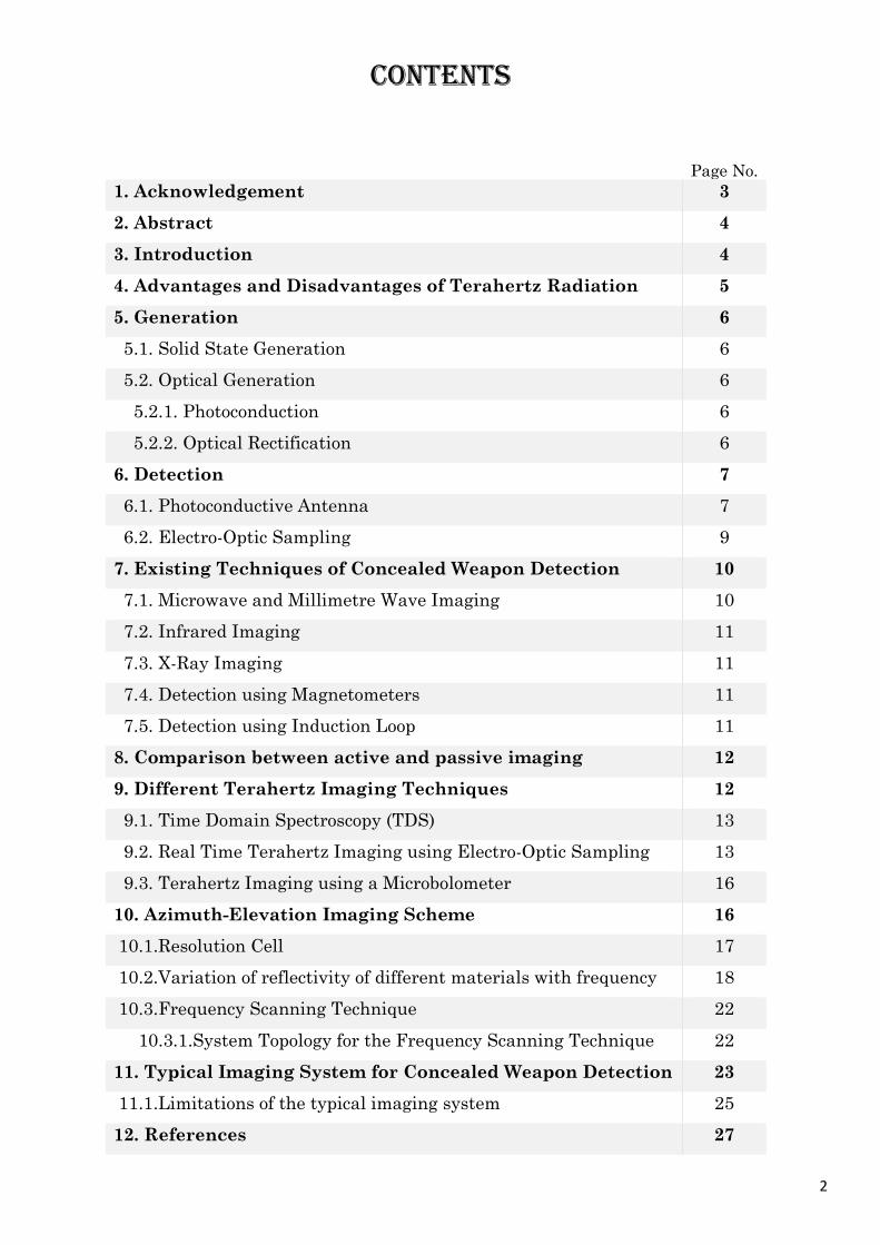
The Terahertz frequency region extends from 0.3 THz to 3 THz [1] and lies between the
microwave and infrared regions in the electromagnetic spectrum [2] as shown in fig.1 [3].
The increase in terrorist activities like aircraft hijackings, railway bombings, etc. over the
past few years have led to an unprecedented increase in the demand for security
screening of passengers at such ports. Terahertz radiations (which are known as
submillimetre waves) have small wavelengths, high penetrability and most significantly
is not hazardous to the human body and hence its use in concealed weapon detection
has been a field of intense interest and research. The main limitation to the use of
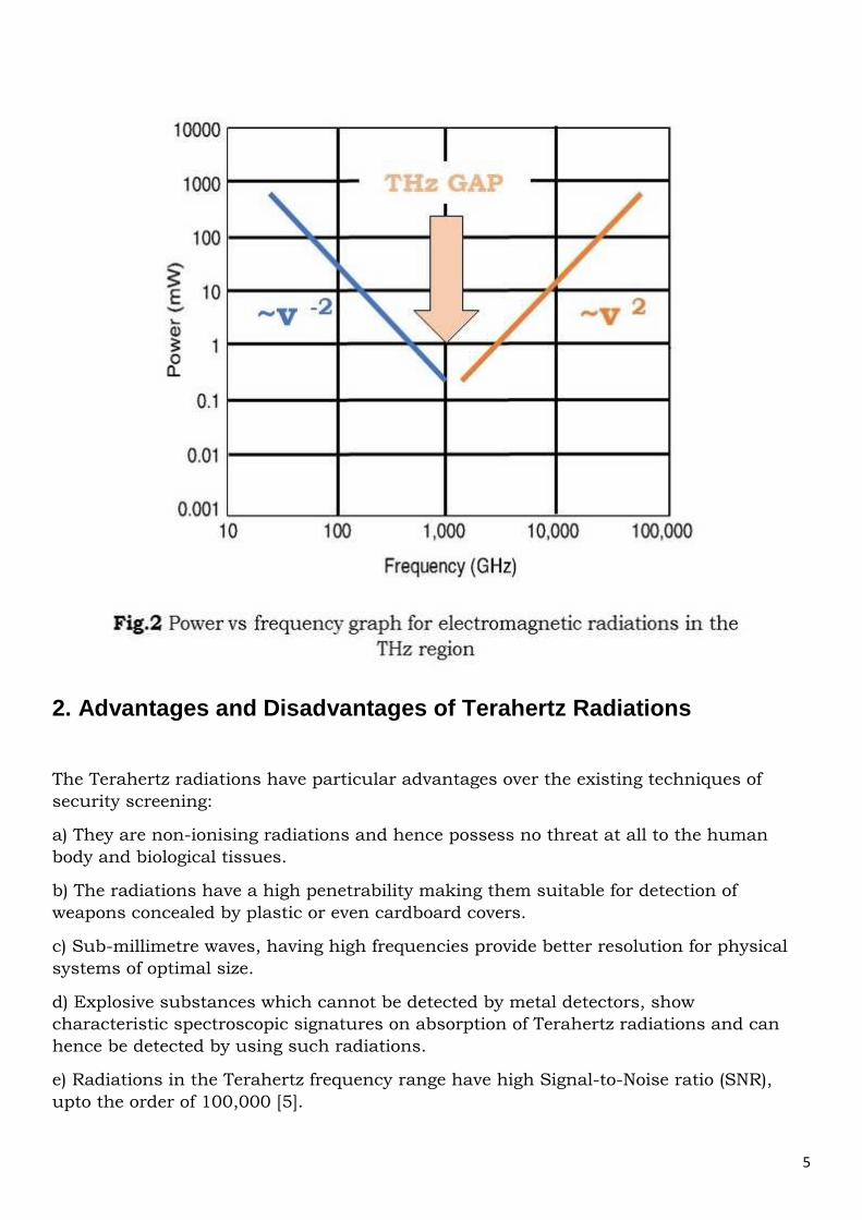
Terahertz technology however, is the low power of the signals as shown in fig.2 [4] and
hence the difficulty in detecting it by ordinary detection systems. As a result of this, the
Terahertz region has remained inaccessible for a long period of time and the void in
scientific knowledge thus produced is known as “Terahertz gap”.
5
2. Advantages and Disadvantages of Terahertz Radiations
The Terahertz radiations have particular advantages over the existing techniques of
security screening:
a) They are non-ionising radiations and hence possess no threat at all to the human
body and biological tissues.
b) The radiations have a high penetrability making them suitable for detection of
weapons concealed by plastic or even cardboard covers.
c) Sub-millimetre waves, having high frequencies provide better resolution for physical
systems of optimal size.
d) Explosive substances which cannot be detected by metal detectors, show
characteristic spectroscopic signatures on absorption of Terahertz radiations and can
hence be detected by using such radiations.
e) Radiations in the Terahertz frequency range have high Signal-to-Noise ratio (SNR),
upto the order of 100,000 [5].
6
The Terahertz imaging and detection systems are mostly limited by high absorption in
water, biological tissues and other polar liquids. The present systems of Terahertz
imaging is constrained by low acquisition speed while the generation systems are
controlled by low frequency bandwidth. While frequencies upto 3 or 4 THz can be
generated by photoconduction techniques, higher frequencies about 30 THz can be
generated by processes like optical rectification which seriously compromise the Signal-
to-Noise Ratio (SNR). The Terahertz sensing and imaging techniques although affordable
for research purposes are quite expensive for commercial usage.
3. Generation
One of the reasons for the limited usage of Terahertz frequencies in concealed weapon
detection is the difficulty in its generation. Two relevant methods of Terahertz wave
generation is the process of Solid-State Generation and the process of Optical
Generation. Recently, processes related to and properties of Semiconductor sources are
being used to generate sub-millimetre waves. The following section discusses about the
various methods of generation of Terahertz waves.
I. Solid-State Generation
Although a very effective way for generation of Infrared waves, the main limitation this
method faces in the generation of THz waves is the unsuitability of the semiconductor
devices for this type of excitation. The method presently being researched is the
quantum cascade concept. Unlike semiconductor lasers that emit electromagnetic
radiations through electron-hole pair recombination, the quantum cascade lasers
achieves laser emissions through intersubband transitions [6]. This method is however
incapable of generating frequencies less than 10 THz at room temperature. At cryogenic
temperatures, this process can generate waves of frequencies as low as 4.4 THz.
II. Optical Generation
This method does not make use of any semiconductor bands for emission of THz waves.
Instead it uses laser of pulse width 10fs to 200fs which is either reflected or transmitted
through a THz generator. Photoconduction and Optical Rectification are the two sub
parts of the method of optical generation.
A. Photoconduction
In this process an optical laser (pulse width = 100 fs or less) is used to overcome the
forbidden energy gap GaSe semiconductor. This process results in a small amount of
current which is used to drive the radiating antennae. This process generates THz waves
of more power as compared to the optical rectification process.
B. Optical Rectification
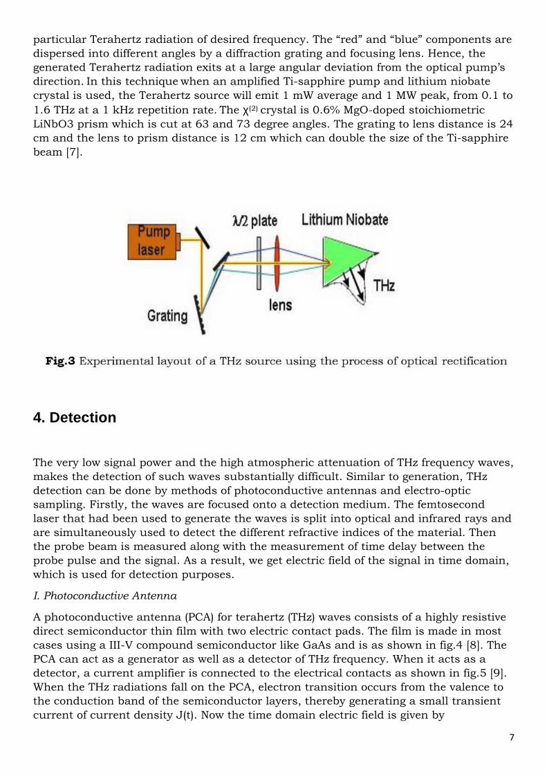
In this technique χ(2) crystals and optical pumps are used to convert optical frequency to
Terahertz frequency. This frequency conversion technique is a non-linear one and is
called optical rectification. The generation of Terahertz frequency from the setup as
shown in fig.3 [7] may be described as follows: the 115 fs pulse generated by the laser
pump contains numerous Terahertz frequency components. So the ‘red’ and ‘blue’
components of a single optical pulse is made to ‘mix’ in a χ(2) crystal producing a
7
particular Terahertz radiation of desired frequency. The “red” and “blue” components are
dispersed into different angles by a diffraction grating and focusing lens. Hence, the
generated Terahertz radiation exits at a large angular deviation from the optical pump’s
direction. In this technique when an amplified Ti-sapphire pump and lithium niobate
crystal is used, the Terahertz source will emit 1 mW average and 1 MW peak, from 0.1 to
1.6 THz at a 1 kHz repetition rate. The χ(2) crystal is 0.6% MgO-doped stoichiometric
LiNbO3 prism which is cut at 63 and 73 degree angles. The grating to lens distance is 24
cm and the lens to prism distance is 12 cm which can double the size of the Ti-sapphire
beam [7].
4. Detection
The very low signal power and the high atmospheric attenuation of THz frequency waves,
makes the detection of such waves substantially difficult. Similar to generation, THz
detection can be done by methods of photoconductive antennas and electro-optic
sampling. Firstly, the waves are focused onto a detection medium. The femtosecond
laser that had been used to generate the waves is split into optical and infrared rays and
are simultaneously used to detect the different refractive indices of the material. Then
the probe beam is measured along with the measurement of time delay between the
probe pulse and the signal. As a result, we get electric field of the signal in time domain,
which is used for detection purposes.
I. Photoconductive Antenna
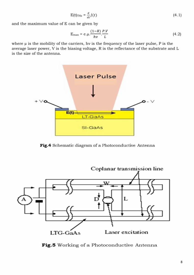
A photoconductive antenna (PCA) for terahertz (THz) waves consists of a highly resistive
direct semiconductor thin film with two electric contact pads. The film is made in most
cases using a III-V compound semiconductor like GaAs and is as shown in fig.4 [8]. The
PCA can act as a generator as well as a detector of THz frequency. When it acts as a
detector, a current amplifier is connected to the electrical contacts as shown in fig.5 [9].
When the THz radiations fall on the PCA, electron transition occurs from the valence to
the conduction band of the semiconductor layers, thereby generating a small transient
current of current density J(t). Now the time domain electric field is given by
8
E(t)THz = �
���(�) (4.1)
and the maximum value of E can be given by
Emax = e.µ.(��)
�.�.�
� (4.2)
where µ is the mobility of the carriers, hν is the frequency of the laser pulse, P is the
average laser power, V is the biasing voltage, R is the reflectance of the substrate and L
is the size of the antenna.
9
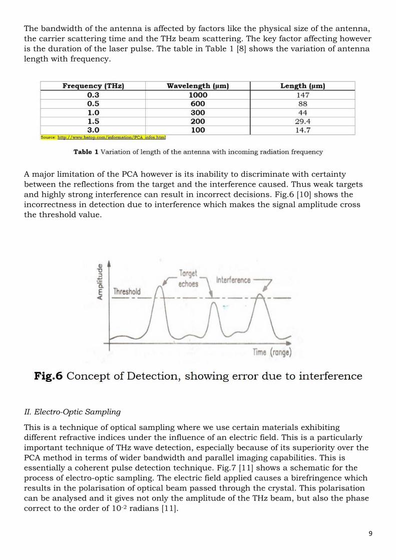
The bandwidth of the antenna is affected by factors like the physical size of the antenna,
the carrier scattering time and the THz beam scattering. The key factor affecting however
is the duration of the laser pulse. The table in Table 1 [8] shows the variation of antenna
length with frequency.
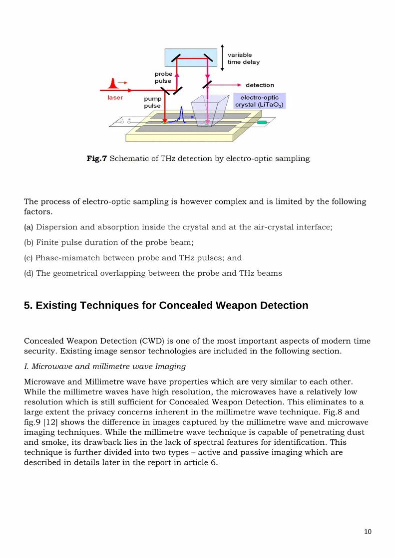
A major limitation of the PCA however is its inability to discriminate with certainty
between the reflections from the target and the interference caused. Thus weak targets
and highly strong interference can result in incorrect decisions. Fig.6 [10] shows the
incorrectness in detection due to interference which makes the signal amplitude cross
the threshold value.
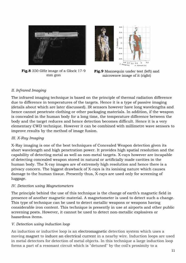
II. Electro-Optic Sampling
This is a technique of optical sampling where we use certain materials exhibiting
different refractive indices under the influence of an electric field. This is a particularly
important technique of THz wave detection, especially because of its superiority over the
PCA method in terms of wider bandwidth and parallel imaging capabilities. This is
essentially a coherent pulse detection technique. Fig.7 [11] shows a schematic for the
process of electro-optic sampling. The electric field applied causes a birefringence which
results in the polarisation of optical beam passed through the crystal. This polarisation
can be analysed and it gives not only the amplitude of the THz beam, but also the phase
correct to the order of 10-2 radians [11].
10
The process of electro-optic sampling is however complex and is limited by the following
factors.
(a) Dispersion and absorption inside the crystal and at the air-crystal interface;
(b) Finite pulse duration of the probe beam;
(c) Phase-mismatch between probe and THz pulses; and
(d) The geometrical overlapping between the probe and THz beams
5. Existing Techniques for Concealed Weapon Detection
Concealed Weapon Detection (CWD) is one of the most important aspects of modern time
security. Existing image sensor technologies are included in the following section.
I. Microwave and millimetre wave Imaging
Microwave and Millimetre wave have properties which are very similar to each other.
While the millimetre waves have high resolution, the microwaves have a relatively low
resolution which is still sufficient for Concealed Weapon Detection. This eliminates to a
large extent the privacy concerns inherent in the millimetre wave technique. Fig.8 and
fig.9 [12] shows the difference in images captured by the millimetre wave and microwave
imaging techniques. While the millimetre wave technique is capable of penetrating dust
and smoke, its drawback lies in the lack of spectral features for identification. This
technique is further divided into two types – active and passive imaging which are
described in details later in the report in article 6.
11
II. Infrared Imaging
The infrared imaging technique is based on the principle of thermal radiation difference
due to difference in temperatures of the targets. Hence it is a type of passive imaging
(details about which are later discussed). IR sensors however have long wavelengths and
hence cannot penetrate clothing or other packaging materials. In addition, if the weapon
is concealed in the human body for a long time, the temperature difference between the
body and the target reduces and hence detection becomes difficult. Hence it is a very
elementary CWD technique. However it can be combined with millimetre wave sensors to
improve results by the method of image fusion.
III. X-Ray Imaging
X-Ray imaging is one of the best techniques of Concealed Weapon detection given its
short wavelength and high penetration power. It provides high spatial resolution and the
capability of detecting metal as well as non-metal targets. X-rays however are incapable
of detecting concealed weapon stored in natural or artificially made cavities in the
human body. The X-ray images are of extremely high resolution and hence there is a
privacy concern. The biggest drawback of X-rays is its ionising nature which causes
damage to the human tissue. Presently thus, X-rays are used only for screening of
luggage.
IV. Detection using Magnetometers
The principle behind the use of this technique is the change of earth’s magnetic field in
presence of another magnetic material. A magnetometer is used to detect such a change.
This type of technique can be used to detect metallic weapons or weapons having
considerable iron content. This technique is presently in use at airports and other public
screening posts. However, it cannot be used to detect non-metallic explosives or
hazardous items.
V. Detection using induction loop
An induction or inductive loop is an electromagnetic detection system which uses a
moving magnet to induce an electrical current in a nearby wire. Induction loops are used
in metal detectors for detection of metal objects. In this technique a large induction loop
forms a part of a resonant circuit which is "detuned" by the coil's proximity to a
12
conductive object. Apart from metallic, conductive or capacitive objects can also be
detected.
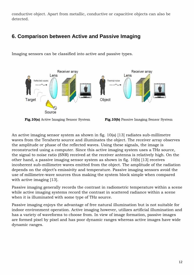
6. Comparison between Active and Passive Imaging
Imaging sensors can be classified into active and passive types.
An active imaging sensor system as shown in fig. 10(a) [13] radiates sub-millimetre
waves from the Terahertz source and illuminates the object. The receiver array observes
the amplitude or phase of the reflected waves. Using these signals, the image is
reconstructed using a computer. Since this active imaging system uses a THz source,
the signal to noise ratio (SNR) received at the receiver antenna is relatively high. On the
other hand, a passive imaging sensor system as shown in fig. 10(b) [13] receives
incoherent sub-millimetre waves emitted from the object. The amplitude of the radiation
depends on the object’s emissivity and temperature. Passive imaging sensors avoid the
use of millimetre-wave sources thus making the system block simple when compared
with active imaging [13].
Passive imaging generally records the contrast in radiometric temperature within a scene
while active imaging systems record the contrast in scattered radiance within a scene
when it is illuminated with some type of THz source.
Passive imaging enjoys the advantage of free natural illumination but is not suitable for
indoor environment operation. Active imaging however, utilizes artificial illumination and
has a variety of waveforms to choose from. In view of image formation, passive images
are formed pixel by pixel and has poor dynamic ranges whereas active images have wide
dynamic ranges.
13
7. Different Terahertz Imaging Techniques
The objective of T-ray imaging is to produce images with ‘component contrast’. T-ray
imaging techniques, having longer wavelengths compared to microwaves can provide
enhanced contrast because of lower scattering ability. Various T-ray imaging techniques
include Time Domain Spectroscopy (TDS), electro-optic sampling, tomographic and
single shot imaging. Imaging with electromagnetic pulses in the Terahertz region is also
popular for real world applications as it can provide non-invasive monitoring methods.
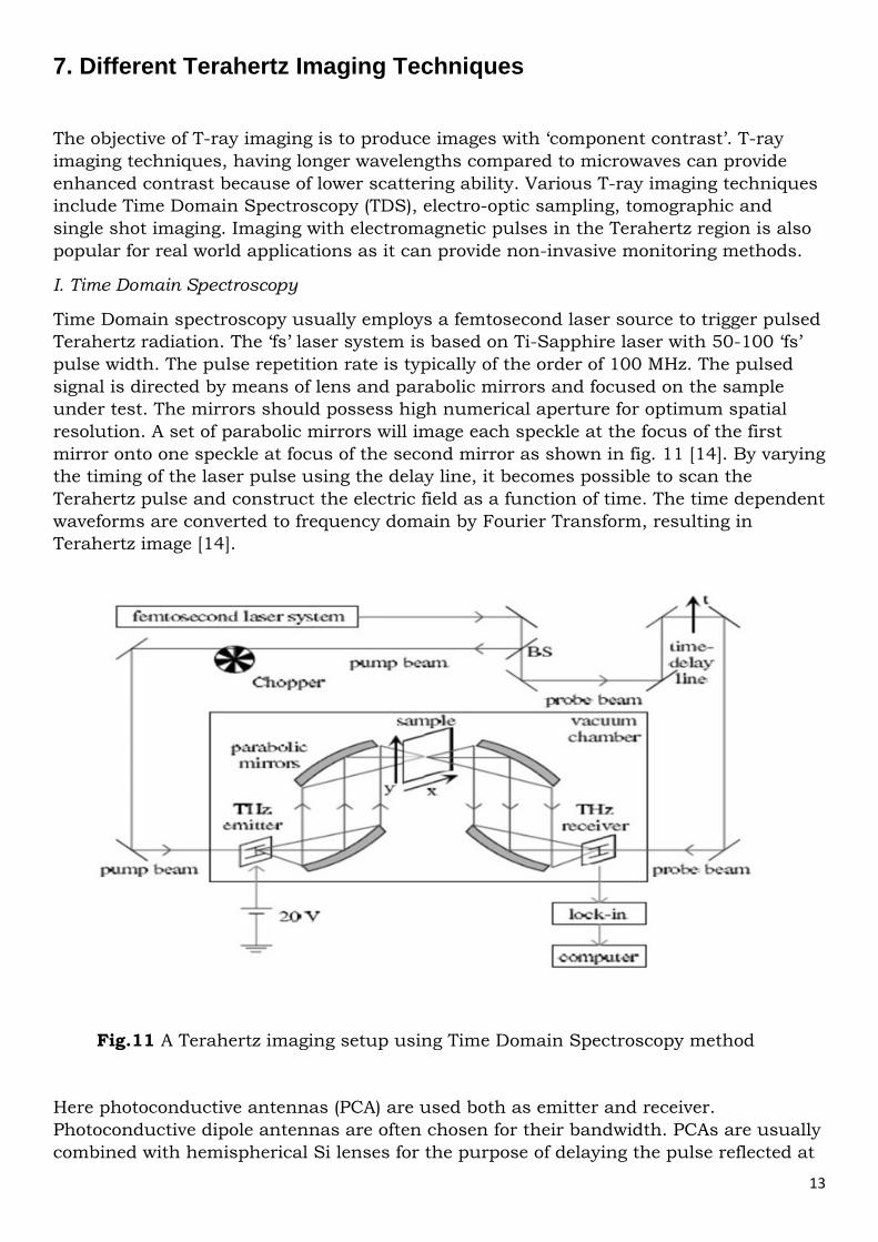
I. Time Domain Spectroscopy
Time Domain spectroscopy usually employs a femtosecond laser source to trigger pulsed
Terahertz radiation. The ‘fs’ laser system is based on Ti-Sapphire laser with 50-100 ‘fs’
pulse width. The pulse repetition rate is typically of the order of 100 MHz. The pulsed
signal is directed by means of lens and parabolic mirrors and focused on the sample
under test. The mirrors should possess high numerical aperture for optimum spatial
resolution. A set of parabolic mirrors will image each speckle at the focus of the first
mirror onto one speckle at focus of the second mirror as shown in fig. 11 [14]. By varying
the timing of the laser pulse using the delay line, it becomes possible to scan the
Terahertz pulse and construct the electric field as a function of time. The time dependent
waveforms are converted to frequency domain by Fourier Transform, resulting in
Terahertz image [14].
Here photoconductive antennas (PCA) are used both as emitter and receiver.
Photoconductive dipole antennas are often chosen for their bandwidth. PCAs are usually
combined with hemispherical Si lenses for the purpose of delaying the pulse reflected at
Fig.11 A Terahertz imaging setup using Time Domain Spectroscopy method
14
the second surface of the antenna chip and thus preventing oscillations in the Terahertz
spectrum.
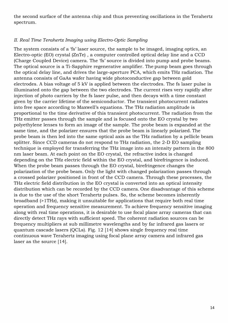
II. Real Time Terahertz Imaging using Electro-Optic Sampling
The system consists of a ‘fs’ laser source, the sample to be imaged, imaging optics, an
Electro-optic (EO) crystal (ZnTe) , a computer controlled optical delay line and a CCD
(Charge Coupled Device) camera. The ‘fs’ source is divided into pump and probe beams.
The optical source is a Ti-Sapphire regenerative amplifier. The pump beam goes through
the optical delay line, and drives the large-aperture PCA, which emits THz radiation. The
antenna consists of GaAs wafer having wide photoconductive gap between gold
electrodes. A bias voltage of 5 kV is applied between the electrodes. The fs laser pulse is
illuminated onto the gap between the two electrodes. The current rises very rapidly after
injection of photo carriers by the fs laser pulse, and then decays with a time constant
given by the carrier lifetime of the semiconductor. The transient photocurrent radiates
into free space according to Maxwell’s equations. The THz radiation amplitude is
proportional to the time derivative of this transient photocurrent. The radiation from the
THz emitter passes through the sample and is focused onto the EO crystal by two
polyethylene lenses to form an image of the sample. The probe beam is expanded at the
same time, and the polarizer ensures that the probe beam is linearly polarized. The
probe beam is then led into the same optical axis as the THz radiation by a pellicle beam
splitter. Since CCD cameras do not respond to THz radiation, the 2-D EO sampling
technique is employed for transferring the THz image into an intensity pattern in the 800
nm laser beam. At each point on the EO crystal, the refractive index is changed
depending on the THz electric field within the EO crystal, and birefringence is induced.
When the probe beam passes through the EO crystal, birefringence changes the
polarization of the probe beam. Only the light with changed polarization passes through
a crossed polarizer positioned in front of the CCD camera. Through these processes, the
THz electric field distribution in the EO crystal is converted into an optical intensity
distribution which can be recorded by the CCD camera. One disadvantage of this scheme
is due to the use of the short Terahertz pulses. So, the scheme becomes inherently
broadband (>1THz), making it unsuitable for applications that require both real time
operation and frequency sensitive measurement. To achieve frequency sensitive imaging
along with real time operations, it is desirable to use focal plane array cameras that can
directly detect THz rays with sufficient speed. The coherent radiation sources can be
frequency multipliers at sub millimetre wavelengths and by far infrared gas lasers or
quantum cascade lasers (QCLs). Fig. 12 [14] shows single frequency real time
continuous wave Terahertz imaging using focal plane array camera and infrared gas
laser as the source [14].
15
Fig.12 A schematic diagram of the real time THz imaging using electro-optic sampling
16
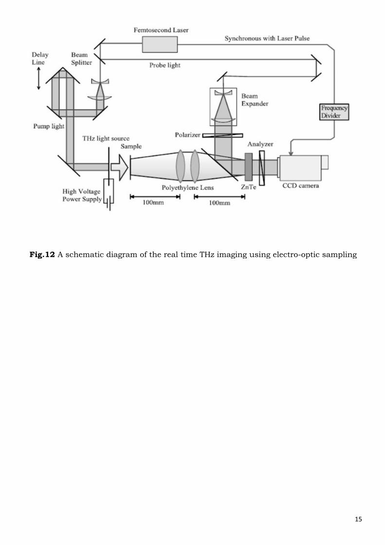
III. Terahertz Imaging using a micro-bolometer
The Terahertz imaging system shown in fig.13 [15] is an uncooled micro bolometer focal plane array camera. The Terahertz beam is allowed to expand at 1.4◦ divergence angle of the laser. The reflected beam backlights an object with a maximum area of roughly 4cm×4cm and the transmitted light is received by a germanium camera lens. The focal plane is situated approximately 1.1 cm behind the germanium camera lens. A 6.5 mm thick sheet of high density polyethylene (HDPE) is placed directly in front of the camera to provide uniform background. The distance between the off-axis paraboloid and the germanium lens is fixed to collimate the light emerging from the lens. Concentrating the signal over a smaller area improves the signal/noise ratio (SNR). At the brightest illumination point, the centre of the image, the SNR is estimated to be 13 dB. Significant improvements in SNR and spatial resolution can be made by designing focal-plane micro bolometer cameras specifically optimized for THz frequencies.
8. Azimuth-Elevation Imaging Schemes
Concealed Weapon detection using Terahertz frequency mainly involves active imaging
techniques. Passive imaging is usually not used because of some disadvantages which
have been already discussed. So, we basically require a radar like system. The Azimuth-
Elevation imaging scheme is a popular one that can be used.
An azimuth is an angular measurement in a spherical coordinate system. The vector
from an observer to a point of interest is projected perpendicularly onto a reference
Fig.13 Experimental setup of THz imaging using a microbolometer
17
plane. The angle between the projected vector and a reference vector on the reference
plane is called the azimuth.
Elevation is defined as the angle between the object and the observer’s local horizon.
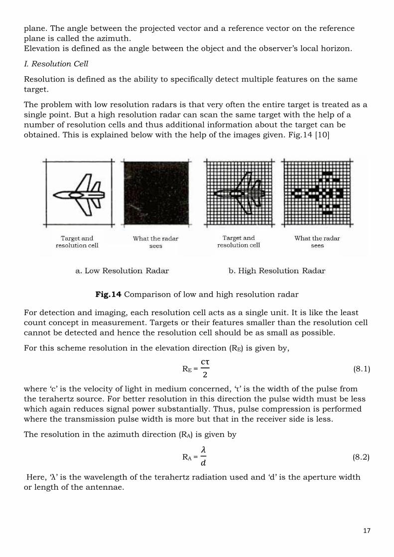
I. Resolution Cell
Resolution is defined as the ability to specifically detect multiple features on the same
target.
The problem with low resolution radars is that very often the entire target is treated as a
single point. But a high resolution radar can scan the same target with the help of a
number of resolution cells and thus additional information about the target can be
obtained. This is explained below with the help of the images given. Fig.14 [10]
For detection and imaging, each resolution cell acts as a single unit. It is like the least
count concept in measurement. Targets or their features smaller than the resolution cell
cannot be detected and hence the resolution cell should be as small as possible.
For this scheme resolution in the elevation direction (RE) is given by,
RE = ��
� (8.1)
where ‘c’ is the velocity of light in medium concerned, ‘τ’ is the width of the pulse from
the terahertz source. For better resolution in this direction the pulse width must be less
which again reduces signal power substantially. Thus, pulse compression is performed
where the transmission pulse width is more but that in the receiver side is less.
The resolution in the azimuth direction (RA) is given by
RA = �
� (8.2)
Here, ‘λ’ is the wavelength of the terahertz radiation used and ‘d’ is the aperture width
or length of the antennae.
Fig.14 Comparison of low and high resolution radar
18
The basic principle of the detection and imaging by this scheme is given next.
We can begin with the radar equations [10]. The power that is radiated effectively in the
direction of the main beam is called effective radiated power (ERP) given by
ERP (in Watts) = (PTGT) (8.3)
Here, PT is the transmit power delivered to the antenna (Watts) and GT is the gain of the
radar’s transmit antenna. The transmit power is actually the power from the THz source
(we are using an active imaging system).
Next, we consider the forward (illumination) power density at the target, P/A which is
given by
�
� (in Watts per square meter) =
��
������
(8.4)
Here, RT is the range from radar transmitted to target (in meters) and 4ПRT2 is the
surface area of the sphere of radius RT. This power density (P/A) is the amount of power
falling on each unit area of a plane perpendicular to the axis of the antenna at a
distance RT from the radar.
The effective power reflected by the target in the direction of the radar (Ptgt) is directly
proportional to P/A and reflection characteristics of the target which is given by
Ptgt = �
� σ (8.5)
where, σ is the target’s radar cross-section which depends mainly on the reflection
characteristics of the target.
The energy reflected from the target propagates away from it at the propagation velocity.
The power density in the backscattered wave at the radar is the power effectively
isotropically radiated by the target divided by the surface of a sphere of radius equal to
the range from target to radar. There is no gain factor in backscatter propagation since
the target is treated as though it were isotropic. In a monostatic radar, the range from
the target to the radar’s receiving antenna equals the range from radar’s transmitting
antenna to target. This is given by the following equation
�
�� =
�����
�������
� (8.6)
where, P/AB is the backscatter power density at the radar’s receiving antenna (Watts
per square meter) and RR is the range from the target to the radar’s receiving antenna
(meters).
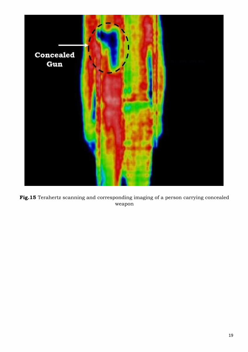
II. Variation of Reflectivity of different materials with frequency
Depending on varying σ, the different parts of the target pick up different colours or
signatures on the detected image as shown in the fig.15 [17].
19
Fig.15 Terahertz scanning and corresponding imaging of a person carrying concealed
weapon
20
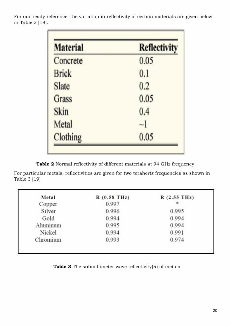
For our ready reference, the variation in reflectivity of certain materials are given below
in Table 2 [18].
For particular metals, reflectivities are given for two terahertz frequencies as shown in
Table 3 [19]
Table 2 Normal reflectivity of different materials at 94 GHz frequency
Table 3 The submillimeter wave reflectivity(R) of metals
21
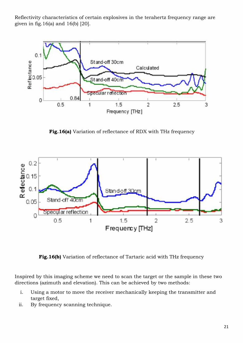
Reflectivity characteristics of certain explosives in the terahertz frequency range are
given in fig.16(a) and 16(b) [20].
Inspired by this imaging scheme we need to scan the target or the sample in these two
directions (azimuth and elevation). This can be achieved by two methods:
i. Using a motor to move the receiver mechanically keeping the transmitter and
target fixed,
ii. By frequency scanning technique.
Fig.16(a) Variation of reflectance of RDX with THz frequency
Fig.16(b) Variation of reflectance of Tartaric acid with THz frequency
22
III. Frequency Scanning Technique
Frequency scanning antennas, which scan beams by changing frequency are widely
used in imaging applications. Such antennas often utilize the characteristics of a leaky
wave antenna that comprises of a slotted waveguide, where the slot works as the
antenna aperture. The waveguide acts as the transmission line for propagating the
waves radiated from the slot [21].
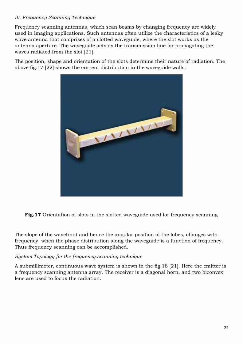
The position, shape and orientation of the slots determine their nature of radiation. The
above fig.17 [22] shows the current distribution in the waveguide walls.
The slope of the wavefront and hence the angular position of the lobes, changes with
frequency, when the phase distribution along the waveguide is a function of frequency.
Thus frequency scanning can be accomplished.
System Topology for the frequency scanning technique
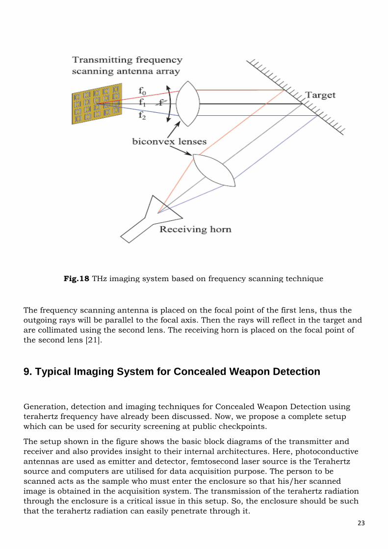
A submillimeter, continuous wave system is shown in the fig.18 [21]. Here the emitter is
a frequency scanning antenna array. The receiver is a diagonal horn, and two biconvex
lens are used to focus the radiation.
Fig.17 Orientation of slots in the slotted waveguide used for frequency scanning
23
The frequency scanning antenna is placed on the focal point of the first lens, thus the
outgoing rays will be parallel to the focal axis. Then the rays will reflect in the target and
are collimated using the second lens. The receiving horn is placed on the focal point of
the second lens [21].
9. Typical Imaging System for Concealed Weapon Detection
Generation, detection and imaging techniques for Concealed Weapon Detection using
terahertz frequency have already been discussed. Now, we propose a complete setup
which can be used for security screening at public checkpoints.
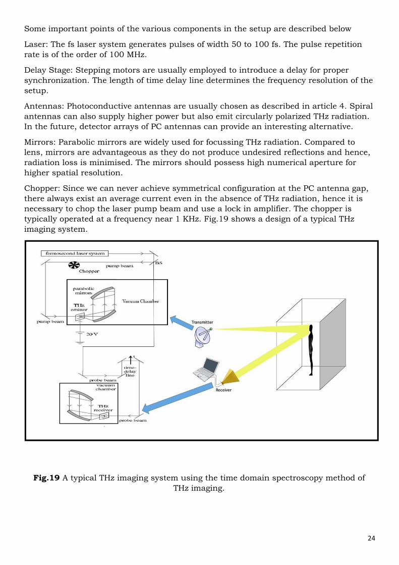
The setup shown in the figure shows the basic block diagrams of the transmitter and
receiver and also provides insight to their internal architectures. Here, photoconductive
antennas are used as emitter and detector, femtosecond laser source is the Terahertz
source and computers are utilised for data acquisition purpose. The person to be
scanned acts as the sample who must enter the enclosure so that his/her scanned
image is obtained in the acquisition system. The transmission of the terahertz radiation
through the enclosure is a critical issue in this setup. So, the enclosure should be such
that the terahertz radiation can easily penetrate through it.
Fig.18 THz imaging system based on frequency scanning technique
24
Some important points of the various components in the setup are described below
Laser: The fs laser system generates pulses of width 50 to 100 fs. The pulse repetition
rate is of the order of 100 MHz.
Delay Stage: Stepping motors are usually employed to introduce a delay for proper
synchronization. The length of time delay line determines the frequency resolution of the
setup.
Antennas: Photoconductive antennas are usually chosen as described in article 4. Spiral
antennas can also supply higher power but also emit circularly polarized THz radiation.
In the future, detector arrays of PC antennas can provide an interesting alternative.
Mirrors: Parabolic mirrors are widely used for focussing THz radiation. Compared to
lens, mirrors are advantageous as they do not produce undesired reflections and hence,
radiation loss is minimised. The mirrors should possess high numerical aperture for
higher spatial resolution.
Chopper: Since we can never achieve symmetrical configuration at the PC antenna gap,
there always exist an average current even in the absence of THz radiation, hence it is
necessary to chop the laser pump beam and use a lock in amplifier. The chopper is
typically operated at a frequency near 1 KHz. Fig.19 shows a design of a typical THz
imaging system.
Fig.19 A typical THz imaging system using the time domain spectroscopy method of
THz imaging.
25
I. Limitations of the Typical Imaging System
i. As discussed earlier, a crucial issue in the design of such a system is the
material with which the enclosure is made. The enclosure should be made of a
material that can be penetrated by THz radiations. ii. Another limitation of the system is the problems that arise due to the near and
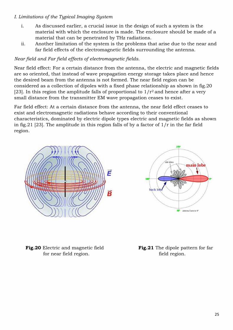
far field effects of the electromagnetic fields surrounding the antenna. Near field and Far field effects of electromagnetic fields.
Near field effect: For a certain distance from the antenna, the electric and magnetic fields
are so oriented, that instead of wave propagation energy storage takes place and hence
the desired beam from the antenna is not formed. The near field region can be
considered as a collection of dipoles with a fixed phase relationship as shown in fig.20
[23]. In this region the amplitude falls of proportional to 1/r2 and hence after a very
small distance from the transmitter EM wave propagation ceases to exist.
Far field effect: At a certain distance from the antenna, the near field effect ceases to
exist and electromagnetic radiations behave according to their conventional
characteristics, dominated by electric dipole types electric and magnetic fields as shown
in fig.21 [23]. The amplitude in this region falls of by a factor of 1/r in the far field
region.
Fig.20 Electric and magnetic field Fig.21 The dipole pattern for far
for near field region. field region.
26
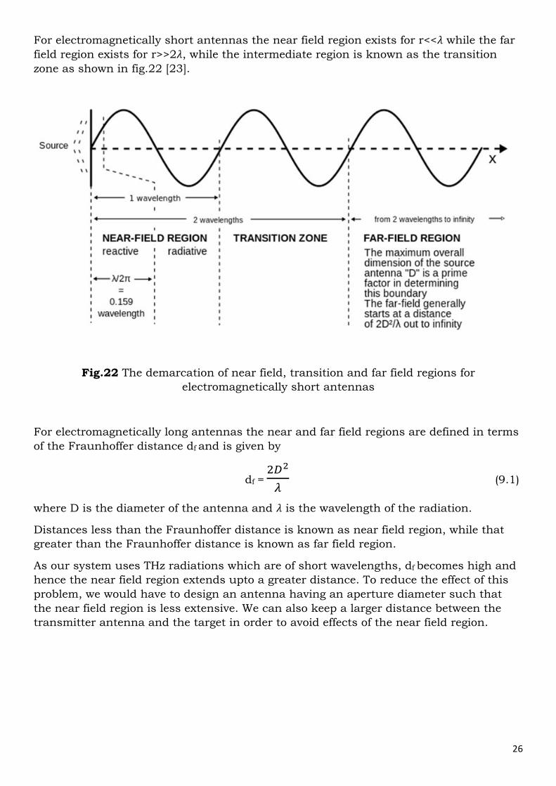
For electromagnetically short antennas the near field region exists for r<<� while the far
field region exists for r>>2�, while the intermediate region is known as the transition
zone as shown in fig.22 [23].
For electromagnetically long antennas the near and far field regions are defined in terms
of the Fraunhoffer distance df and is given by
df = � �
� (9.1)
where D is the diameter of the antenna and � is the wavelength of the radiation.
Distances less than the Fraunhoffer distance is known as near field region, while that
greater than the Fraunhoffer distance is known as far field region.
As our system uses THz radiations which are of short wavelengths, df becomes high and
hence the near field region extends upto a greater distance. To reduce the effect of this
problem, we would have to design an antenna having an aperture diameter such that
the near field region is less extensive. We can also keep a larger distance between the
transmitter antenna and the target in order to avoid effects of the near field region.
Fig.22 The demarcation of near field, transition and far field regions for
electromagnetically short antennas
27
References
1. M. C. Kemp, ‘Detecting hidden objects: Security imaging using millimetre-waves and terahertz (Overview talk)’.
2. Wikipedia – Terahertz radiation.
(http://en.wikipedia.org/wiki/Terahertz_radiation)
3. A disruptive terahertz technology. (http://teracascade.com/technology.php?lang=en)
4. Source: (http://opticalengineering.spiedigitallibrary.org/article.aspx?articleid=1668918).
5. X-C Zhang, ‘Terahertz wave imaging - horizons and hurdles’.
6. R.F. Kazarinov and R.A. Suris, ‘Possibility of amplification of electromagnetic waves in a semiconductor with a super lattice’.
7. Jerry C. Chen, M. Jalal Khan, Zong-Long Liau and Sumanth Kaushik ‘Terahertz generation and detection using nonlinear frequency conversion’.
8. PCA - Photoconductive Antenna for THz Applications. (http://www.batop.com/information/PCA_infos.html)
9. An Introduction to Terahertz Electromagnetic Waves Generation, Detection, Properties and Applications.
10. ‘Radar: Principles, Technology and Application’ by Byron Edde. 11. Time-resolved optoelectronics measurement techniques. 12. Source: (http://www.ptb.de/cms/en/fachabteilungen/abt2/fb-25/ag-254/time-
resolved-optoelectronic-measurement-techniques.html) 13. Leonardo Carrer, ‘Concealed Weapon Detection (Microwave Imaging Approach)’. 14. Masaru Sato and Kozi Muzino, ‘Millimeter-Wave Imaging Sensors’. 15. Michael Herrmann, Ryoichi Fukasawa and Osamu Morikawa, ‘Terahertz imaging’. 16. Alan Wei Min Lee and Qing Hu, ‘Real-Time, continuous-wave terahertz imaging by
use of a microbolometer focal-plane array’. 17. Source: (http://www.gizmag.com/prototype-handheld-scanner-police-
search/11925/). 18. Roger Appleby and Rupert N. Anderton, ‘Millimeter-Wave and Submillimeter-Wave
Imaging for Security and Surveillance’. 19. Robert H. Giles, ‘Characterization of Material Properties at Terahertz Frequencies’. 20. N.Palka, ‘THz Reflection Spectroscopy of Explosives measured by Time Domain
Spectroscopy’. 21. R. Camblor, S. Ver Hoeye, C. Vazquez, G. Hotopan , M. Fernandez , A. Hadarig
and F. Las-Heras, ‘Sub-millimeter Wave Imaging System based on Frequency Scanning Antenna’.
22. Source: (http://www.miwavetechnoventures.com/horn-antennas.html). 23. Wikipedia – Near and far field.
(http://en.wikipedia.org/wiki/Near_and_far_field)