Embed Size (px)
Citation preview
TDW France-22-E-03-09
1
POLYSTOPP for PE PIPE Big sizes 315 - 355 mm
Operation and Maintenance Instructions*
*The present transitional version of the manual should be updated, upon the
launching of the new design valves.

TDW France-22-E-03-09
2

TDW France-22-E-03-09
3
© Copyright 2019
All rights reserved
T.D. Williamson France
NOTICE
Any operation involving work on pipe containing
liquids or gases under pressure is potentially
hazardous. It is necessary, therefore, that correct
procedures be followed in the use of this equipment to
maintain a safe working environment.
No person should use this equipment who is not fully
trained in the procedures stated in this manual, and
who is not fully aware of the potential hazards
connected with work on pipe containing liquids or
gases under pressure.
The purchaser of this equipment is responsible for the
manner in which this equipment is used and the
training and competence of the operators.
Should any difficulty arise at any time in the use of
this equipment, please contact TDW immediately.
T.D. Williamson (France) S.A.S.
11, rue de l’Atome – Z.I.
B.P. 50081
67802 BISCHHEIM cedex - France
Phone : +33 (0)3 88 19 72 38
Fax +33 (0)3 88 19 72 19
E-mail: [email protected]
Visit TDW’s Web Site at www.tdwilliamson.com
™ Trademark of T.D. Williamson, Inc. in the United States and foreign countries.
® Registered trademark of T.D. Williamson, Inc. in the United States and foreign countries.
TDW France-22-E-03-09
4
Table of Contents
Paragraph Title Page Section I: Introduction
1.0 Description 5
2.0 Scope of Applications 6
3.0 System Components 7
4.0 Safety 9
5.0 Equipment Orientation 9
Section II: Installation and operation of the TDW SHORTCUTT 10 inch valve
1.0 Introduction 10
2.0 Operating instructions 11
Section III: Tapping 315 and 355 mm Lines with the T-203 Tapping Machine 1.0 Introduction 13
2.0 General Information 13
3.0 Preparations 13
4.0 Tapping the Line 18
Section IV: Plugging the Line
1.0 Introduction 20
2.0 Plugging the Main Line 20
Section V: Setting the Completion Plug with the POLYSTOPP Completion Machine
1.0 Preparing the completion machine 30
2.0 Installing the plug 31
3.0 Removal of the valve 32
Section VI: Maintenance
1.0 Introduction 34
2.0 SHORTSTOPP II Plugging Machine 34
3.0 POLYSTOPP completion machine 37
4.0 SHORTCUTT valve 37
Appendix Parts Lists 39

TDW France-22-E-03-09
5
Section I: Introduction
1.0 Description
The POLYSTOPP® Tapping and Plugging
System is designed for use on 315 and 355 mm
polyethylene pipe.
The system is designed for use with TDW
Electrofusion Saddle Fittings. The fittings
permit access to a line to plug it while line work
is being performed.
The entire system includes equipment for
tapping into the line, plugging the main, and
installing a completion plug in the fitting in order
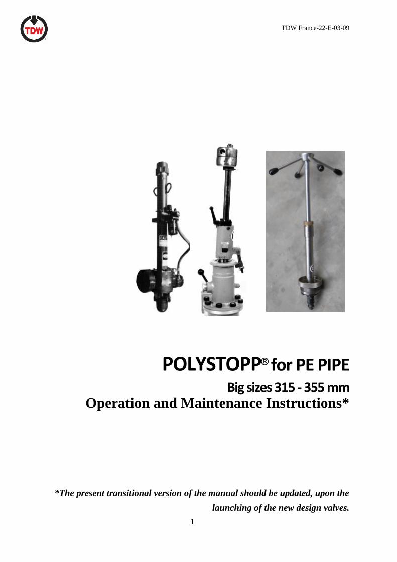
to remove the tapping valve. Some components
of the 315-355 mm system are shown in Figure
1.
Tapping Plugging
Completion
Figure 1. POLYSTOPP System big sizes
for PE Pipe 315-355 mm
This manual describes the procedures for using
this tapping, plugging and completion system to:
• plug the main line, keeping the line in
service.
• to complete the job by setting a
completion plug, enabling removal of
all tapping/plugging equipment.
TDW France-22-E-03-09
6
This manual is intended to aid the safe operation
and proper maintenance of POLYSTOPP® big
sizes 315-355 mm equipment. Read this
manual carefully before attempting to
operate the equipment. If any portion of this
manual is not clearly understood, or if any
questions arise concerning the equipment's use,
contact T.D. Williamson, S.A. or the nearest
factory representative.
WARNING: Do not attempt a plugging and
completion operation without
following the procedures
contained in this manual. A
departure from prescribed
procedures could present a
hazardous situation causing
injury to personnel and
damage to equipment.
Do not alter this equipment or
any of its component parts.
Use only replacement parts
manufactured or
recommended by TDW.
Any alteration of this
equipment, or use of parts not
manufactured or
recommended by TDW could
cause the machine to
malfunction, causing damage
to the equipment and/or injury
to personnel.
Before taking this equipment to the field for an
actual plugging operation, conduct a tapping and
plugging exercise on a length of test pipe to
become familiar with the operational
characteristics of the equipment.
2.0 Scope of Applications
The POLYSTOPP® big sizes equipment can be
used on polyethylene pipe, for tapping and
plugging SDR 11 and SDR 17.6 pipe in sizes 315
and 355 mm for the following applications:
• To temporarily stop flow in the line (using
one plugging machine).
• To isolate a section of the line (using two
plugging machines).
• To set a completion plug in the TDW
polyethylene electrofusion saddle fitting.
A complete job will consist of the following
major steps:
• Installation and testing of the fitting(s).
• Tapping the line through the fitting (s).
• Plugging the main line.
• Setting the completion plug.
• Removing the equipment.

TDW France-22-E-03-09
7
3.0 System Components
3.1 Primary System
A. The tapping machine used with this system
is the TDW T-203 tapping machine for both
315 and 355 mm pipe.
B. The T-203 tapping machine is an air or
hydraulic driven tapping machine used for
315 and 355 mm taps. See figure 2.
Figure 2. T-203 Tapping Machine
C. The SHORTSTOPP II 8x12 Folding Head
Plugging Machine is used with this system
to plug 315- and 355 mm lines. This
plugging machine consist of a control bar,
housing, a jacking mechanism for lowering
and raising the plugging head, and a folding
plugging head which opens into the line,
stopping flow. An example of a folding head
plugging machine is shown in figure 3.
Figure 3. SHORTSTOPP II Plugging Machine
TDW France-22-E-03-09
8
D. When tapping and plugging work is done, a
completion plug must be inserted into the
neck of the fitting using the POLYSTOPP
completion machine. The completion plug
is lowered through the valve and threaded
into position in the neck of the fitting. An
O-ring provides a seal. The completion
machine is shown in Figure 4.
Figure 4. POLYSTOPP Completion Machine
3.2 Accessory Equipment
A. The POLYSTOPP 10" Valve is used with
the POLYSTOPP Big Sizes Plugging
System. See figure 5.
Figure 5. POLYSTOPP 10" Valve (valve design will
be changed after September 2019)
B. Tapping and plug setting machine adapters
are used to connect various equipment
components to the POLYSTOPP 10"
valve. They are flanged on the lower end to
match the valve and threaded on the upper
end to match related equipment. Two such
adapters are shown in Figure 6.
Completion machine Adapter in 2
parts
T-203 Adapter
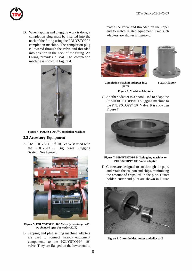
Figure 6. Machine Adapters
C. Another adapter is a spool used to adapt the
8" SHORTSTOPP® II plugging machine to
the POLYSTOPP 10" Valve. It is shown in
Figure 7.
Figure 7. SHORTSTOPP® II plugging machine to
POLYSTOPP 10" Valve adapter
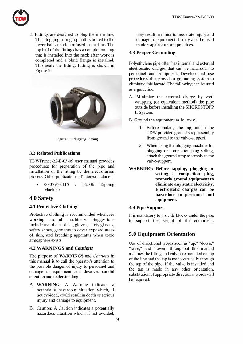
D. Cutters are designed to cut through the pipe,
and retain the coupon and chips, minimizing
the amount of chips left in the pipe. Cutter
holder, cutter and pilot are shown in Figure
8.
Figure 8. Cutter holder, cutter and pilot drill
TDW France-22-E-03-09
9
E. Fittings are designed to plug the main line.
The plugging fitting top half is bolted to the
lower half and electrofused to the line. The
top half of the fittings has a completion plug
that is installed into the neck after work is
completed and a blind flange is installed.
This seals the fitting. Fitting is shown in
Figure 9.
Figure 9 : Plugging Fitting
3.3 Related Publications
TDWFrance-22-E-03-09 user manual provides
procedures for preparation of the pipe and
installation of the fitting by the electrofusion
process. Other publications of interest include:
• 00-3795-0115 : T-203b Tapping
Machine
4.0 Safety
4.1 Protective Clothing
Protective clothing is recommended whenever
working around machinery. Suggestions
include use of a hard hat, gloves, safety glasses,
safety shoes, garments to cover exposed areas
of skin, and breathing apparatus when toxic
atmosphere exists.
4.2 WARNINGS and Cautions
The purpose of WARNINGS and Cautions in
this manual is to call the operator's attention to
the possible danger of injury to personnel and
damage to equipment and deserves careful
attention and understanding.
A. WARNING: A Warning indicates a
potentially hazardous situation which, if
not avoided, could result in death or serious
injury and damage to equipment.
B. Caution: A Caution indicates a potentially
hazardous situation which, if not avoided,
may result in minor to moderate injury and
damage to equipment. It may also be used
to alert against unsafe practices.
4.3 Proper Grounding
Polyethylene pipe often has internal and external
electrostatic charges that can be hazardous to
personnel and equipment. Develop and use
procedures that provide a grounding system to
eliminate this hazard. The following can be used
as a guideline.
A. Minimize the external charge by wet-
wrapping (or equivalent method) the pipe
outside before installing the SHORTSTOPP
II System.
B. Ground the equipment as follows:
1. Before making the tap, attach the
TDW provided ground strap assembly
from ground to the valve-support.
2. When using the plugging machine for
plugging or completion plug setting,
attach the ground strap assembly to the
valve-support.
WARNING: Before tapping, plugging or
setting a completion plug,
properly ground equipment to
eliminate any static electricity.
Electrostatic charges can be
hazardous to personnel and
equipment.
4.4 Pipe Support
It is mandatory to provide blocks under the pipe
to support the weight of the equipment.
5.0 Equipment Orientation
Use of directional words such as "up," "down,"
"raise," and "lower" throughout this manual
assumes the fitting and valve are mounted on top
of the line and the tap is made vertically through
the top of the pipe. If the valve is installed and
the tap is made in any other orientation,
substitution of appropriate directional words will
be required.
TDW France-22-E-03-09
10
Section II: Installation and operation
of the POLYSTOPP 10" Valve
1.0 Introduction
The POLYSTOPP 10" Valve is a full-opening temporary valve used with TDW drilling or tapping machines and
SHORTSTOPP® II plugging equipment. It is recoverable after the tap is complete and a completion plug is set in
the TDW SHORTSTOPP® or POLYSTOPP® fitting.
1.1 Site Preparation
The POLYSTOPP 10" Valve matches ANSI Class 150 bolt patterns.
The compact design of the POLYSTOPP 10" Valve minimizes drilling machine boring bar length required to
complete the tap.
TDW France-22-E-03-09
2.0 Operating instructions
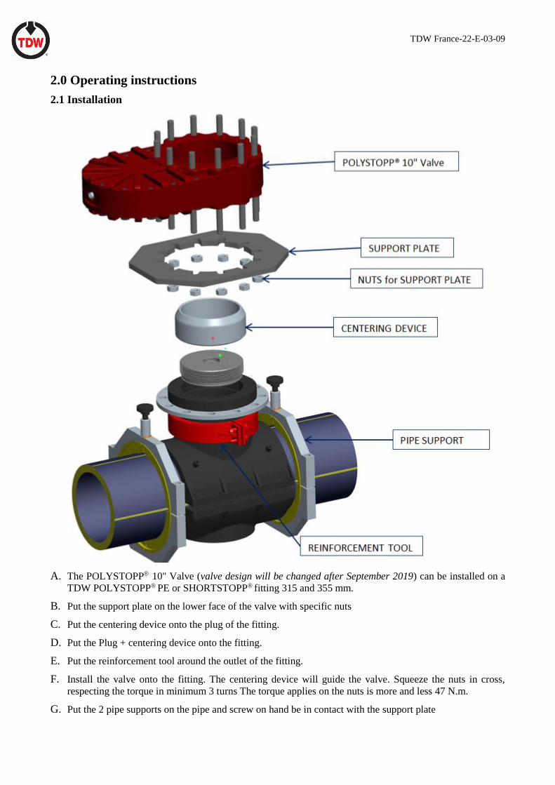
2.1 Installation
A. The POLYSTOPP 10" Valve (valve design will be changed after September 2019) can be installed on a
TDW POLYSTOPP® PE or SHORTSTOPP® fitting 315 and 355 mm.
B. Put the support plate on the lower face of the valve with specific nuts
C. Put the centering device onto the plug of the fitting.
D. Put the Plug + centering device onto the fitting.
E. Put the reinforcement tool around the outlet of the fitting.
F. Install the valve onto the fitting. The centering device will guide the valve. Squeeze the nuts in cross,
respecting the torque in minimum 3 turns The torque applies on the nuts is more and less 47 N.m.
G. Put the 2 pipe supports on the pipe and screw on hand be in contact with the support plate
TDW France-22-E-03-09
H. Remove the centering device with the completion machine. With the effort to remove the plug is too
important, unscrew a little the lower nuts of the valve.
I. The operating handle is used for both opening and closing the valve seat.
2.2 Operation
A. When the valve is installed, and before tapping the pipe, open and close the valve disc. The index indicates
the operating disk is in position fully open.
CAUTION: do not use force to open or close a POLYSTOPP 10" Valve. If a valve will not seal with normal
force, foreign material may be in the path of the valve disc travel, or an O-ring, damaged by failure to
equalize pressure properly, can cause leakage. In these cases, excessive force will not cause a valve to
seal and can damage the valve, possibly resulting in personal injury.
Do not use any tool other than the handle provided to operate the valve.
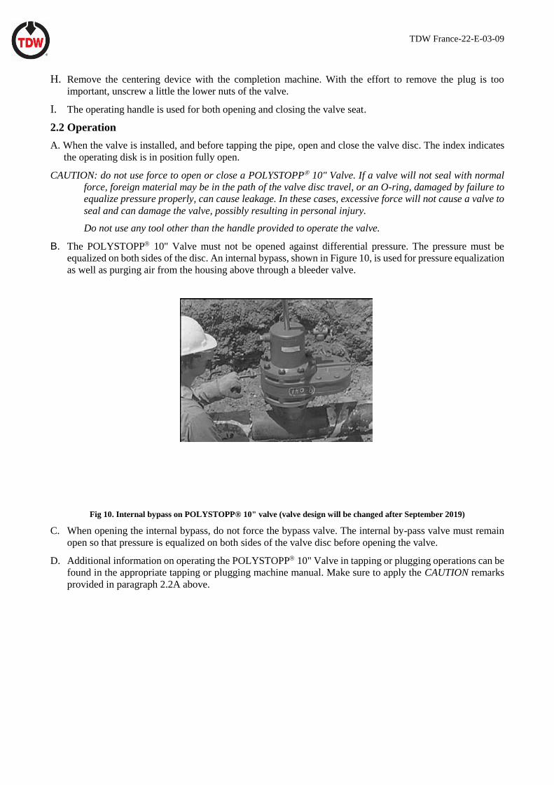
B. The POLYSTOPP 10" Valve must not be opened against differential pressure. The pressure must be
equalized on both sides of the disc. An internal bypass, shown in Figure 10, is used for pressure equalization
as well as purging air from the housing above through a bleeder valve.
Fig 10. Internal bypass on POLYSTOPP® 10" valve (valve design will be changed after September 2019)
C. When opening the internal bypass, do not force the bypass valve. The internal by-pass valve must remain
open so that pressure is equalized on both sides of the valve disc before opening the valve.
D. Additional information on operating the POLYSTOPP 10" Valve in tapping or plugging operations can be
found in the appropriate tapping or plugging machine manual. Make sure to apply the CAUTION remarks
provided in paragraph 2.2A above.
TDW France-22-E-03-09
Section III: Tapping 315 and 355 mm Lines
w/the T-203 Tapping Machine
1.0 Introduction
When tapping a 315 or 355 line, the T-203
Tapping machine is used to make the tap.
It is important that the entire operation be planned
carefully in advance to make sure that all
equipment and fittings necessary to do the job are
readily available.
2.0 General Information
2.1 Procedures
If the line is to be temporarily plugged after
tapping, it should be tapped with product flowing
so that the tapping chips will disperse. If the chips
have been dispersed, a better seal is likely when
the line is plugged off.
2.3 Keeping Line in Service
If a section of line is to be isolated and repaired,
and it is desired to keep the line in service, as
many as six taps of varying sizes could be
required.
A. Two to isolate the section of line.
B. Two to connect a bypass around the isolated
section.
C. One of two connections for blow-down of the
isolated section and equalization of pressure.
D. After the scope of the work has been defined,
the equipment must be selected, assembled,
and inspected to ensure proper working order.
3.0 Preparation
3.1 Fitting
Attach fitting to pipeline following fitting
installation instructions.
3.2 Valve
A. For installing the valve, see the paragraph
2.1 above.
3.3 Tapping Machine
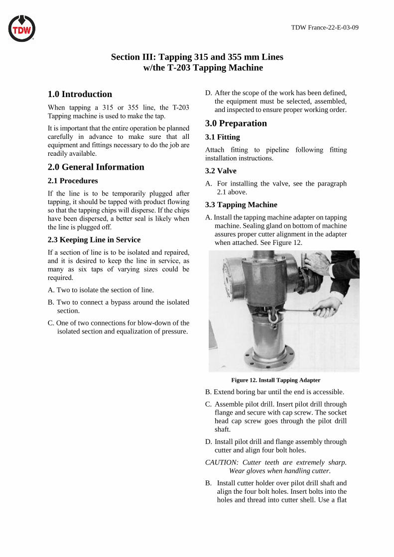
A. Install the tapping machine adapter on tapping
machine. Sealing gland on bottom of machine
assures proper cutter alignment in the adapter
when attached. See Figure 12.
Figure 12. Install Tapping Adapter
B. Extend boring bar until the end is accessible.
C. Assemble pilot drill. Insert pilot drill through
flange and secure with cap screw. The socket
head cap screw goes through the pilot drill
shaft.
D. Install pilot drill and flange assembly through
cutter and align four bolt holes.
CAUTION: Cutter teeth are extremely sharp.
Wear gloves when handling cutter.
B. Install cutter holder over pilot drill shaft and
align the four bolt holes. Insert bolts into the
holes and thread into cutter shell. Use a flat
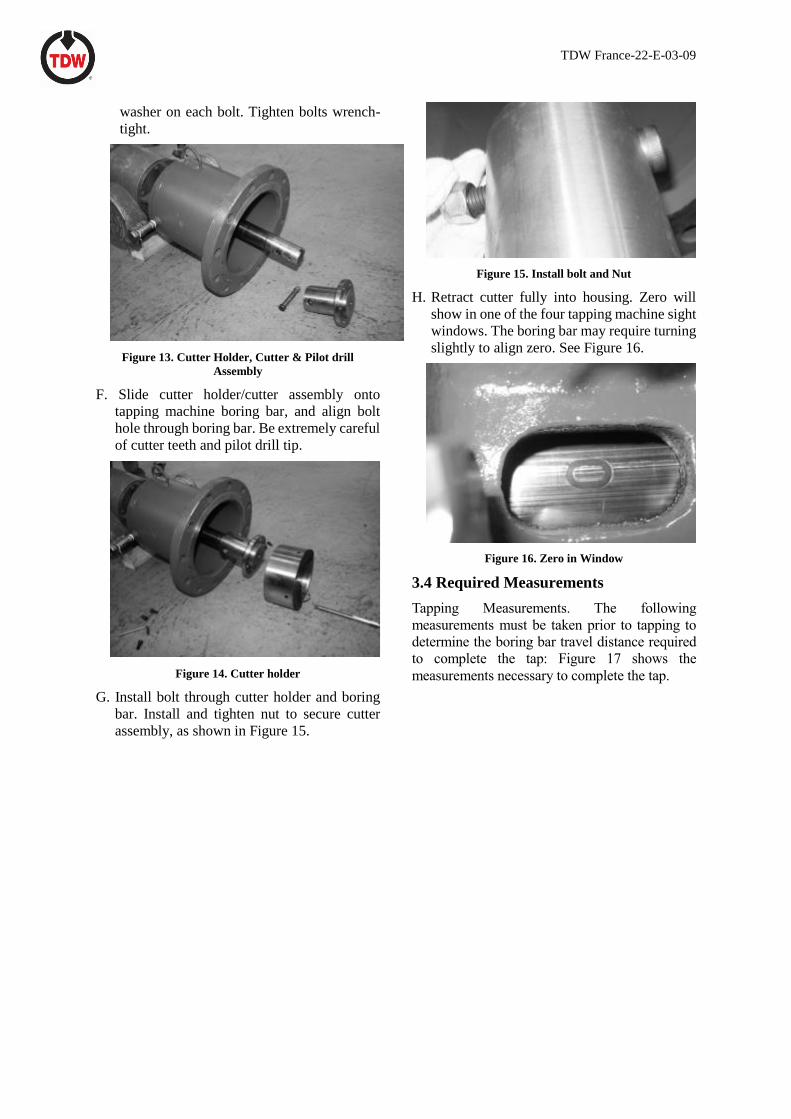
TDW France-22-E-03-09
washer on each bolt. Tighten bolts wrench-
tight.
Figure 13. Cutter Holder, Cutter & Pilot drill
Assembly
F. Slide cutter holder/cutter assembly onto
tapping machine boring bar, and align bolt
hole through boring bar. Be extremely careful
of cutter teeth and pilot drill tip.
Figure 14. Cutter holder
G. Install bolt through cutter holder and boring
bar. Install and tighten nut to secure cutter
assembly, as shown in Figure 15.
Figure 15. Install bolt and Nut
H. Retract cutter fully into housing. Zero will
show in one of the four tapping machine sight
windows. The boring bar may require turning
slightly to align zero. See Figure 16.
Figure 16. Zero in Window
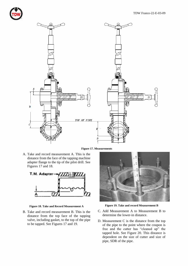
3.4 Required Measurements
Tapping Measurements. The following
measurements must be taken prior to tapping to
determine the boring bar travel distance required
to complete the tap: Figure 17 shows the
measurements necessary to complete the tap.
TDW France-22-E-03-09
Figure 17. Measurements
A. Take and record measurement A. This is the
distance from the face of the tapping machine
adapter flange to the tip of the pilot drill. See
Figures 17 and 18.
Figure 18. Take and Record Measurement A
B. Take and record measurement B. This is the
distance from the top face of the tapping
valve, including gasket, to the top of the pipe
to be tapped. See Figures 17 and 19.
Figure 19. Take and record Measurement B
C. Add Measurement A to Measurement B to
determine the lower-in distance.
D. Measurement C is the distance from the top
of the pipe to the point where the coupon is
free and the cutter has “cleaned up” the
tapped hole. See Figure 20. This distance is
dependent on the size of cutter and size of
pipe, SDR of the pipe.
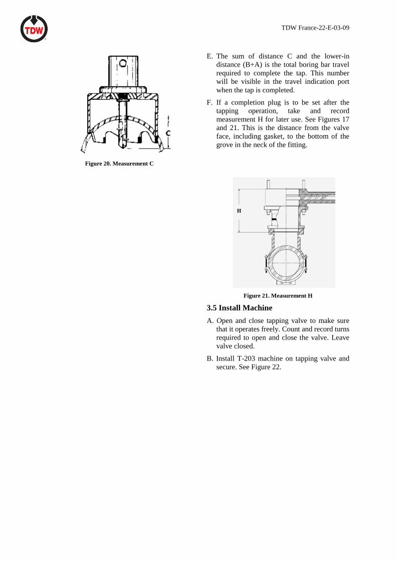
TDW France-22-E-03-09
Figure 20. Measurement C
E. The sum of distance C and the lower-in
distance (B+A) is the total boring bar travel
required to complete the tap. This number
will be visible in the travel indication port
when the tap is completed.
F. If a completion plug is to be set after the
tapping operation, take and record
measurement H for later use. See Figures 17
and 21. This is the distance from the valve
face, including gasket, to the bottom of the
grove in the neck of the fitting.
Figure 21. Measurement H
3.5 Install Machine
A. Open and close tapping valve to make sure
that it operates freely. Count and record turns
required to open and close the valve. Leave
valve closed.
B. Install T-203 machine on tapping valve and
secure. See Figure 22.

TDW France-22-E-03-09
Figure 22. Install T-203 Tapping Machine (valve design
will be changed after September 2019)
C. Install bleeder valve. See figure 23.
Figure 23. Install Bleeder Valve
3.6 Conduct Pressure Test
A. Using the bleeder valve for access, conduct
pressure test on tapping
machine/adapter/valve/fitting installation.
Make sure tapping valve is open for test. Test
to pipeline pressure.
CAUTION: Do not exceed pipe pressure when
conducting pressure test. Exceeding the
piping system internal pressure may
cause damage to the carrier pipe making
it difficult or impossible to complete the
tapping and/or line plugging operation.
B. After test is completed, leave tapping valve
and bleeder valve open.
3.7 Selecting Power Unit
A. If using air motor drive:
1. Prepare air motor. Minimum air supply
must be 105 cfm (2,9736 cubic meter per
minute) at 90 psi (6 bar).
2. Be sure air supply hose is blown clear of
dirt and moisture. Compressor should
have baffled receiver to keep liquid out
of supply line.
3. Attach air hose. See Figure 24.
Figure 24. Connect Air Supply
4. Adjust lubricator to supply approximately
10 drops of oil per minute. A good grade
of SAE 10W engine oil is recommended.
5. Check operation of motor by opening and
closing control valve.

TDW France-22-E-03-09
4.0 Tapping the Line
4.1 Making the Tap
A. Turn feed screw adjusting cap
counterclockwise to relieve spring tension.
See Figure 25.
Figure 25. Turn Feed Screw Adjusting Cap
B. Install lower-in crank in top of machine and
turn counterclockwise, lowering boring bar
until pilot drill touches top of pipe. The
computed lower-in distance (measurements
A and B) should appear in the travel indicator
port. Retract boring bar one revolution and
remove hand crank.
Note: One revolution of the hand crank will lower
the boring bar 1/8 inch. If, for example, the
lower-in distance was 20 inches, it would
require 160 revolutions of the hand crank to
lower the boring bar to this point.
CAUTION: Do not use the air motor or
hydraulic motor to lower the boring bar.
Damage to the cutter and pilot may
occur.
C. Open air control valve (Figure 26) to start
rotation of boring bar. Adjust filter regulator
knob until desired rpm is obtained. The
recommended RPM is between 15 & 20
RPM.
Figure 26. Open Air Control Valve
Note: RPM can be checked easily by observing
the numbers as they come around in the travel
indication port. Count for 15 seconds and
multiply by four to determine rpm.
CAUTION: Speeds higher than 37 rpm may
cause damage and premature wear to
the air motor.
E. Turn feed adjusting cap clockwise to feed pilot
into pipe. Stop adjustment when air motor
begins to load up.
F. As the pilot drill penetrates the pipe wall,
allow line pressure to completely fill valve
and fittings. Blow line liquid or gas through
bleeder valve a few seconds to purge all air.
Close bleeder valve tightly. The machine can
continue tapping during the air purging
process.
WARNING: Vent pressure bleed valve away
from work area and personnel.
Stand clear of vent when
bleeder valve is opened,
otherwise personal injury can
result from blowing material.
G. If the machine stalls, stop and retract cutter a
few turns of the hand crank and resume
tapping.
H. When tap is complete, check number on
boring bar in travel indication port to make
sure computed travel distance has been
reached.
I. Turn off air control valve or close hydraulic
valve to stop boring bar rotation.
J. Turn feed adjusting cap fully counter-
clockwise to stop feed.
K Place hand crank on top of machine and turn
clockwise, fully retracting cutter into tapping
TDW France-22-E-03-09
machine adapter. Zero should appear in the
travel indication port. Remember that it takes
eight turns to retract boring bar 1 inch.
L. Close tapping valve.
M. Open bleeder valve to bleed off pressure in
adapter.
WARNING: Vent pressure bleed valve away
from work area and personnel.
Stand clear of vent when
bleeder valve is opened,
otherwise personal injury can
result from blowing material.
4.2 Remove Tapping Machine
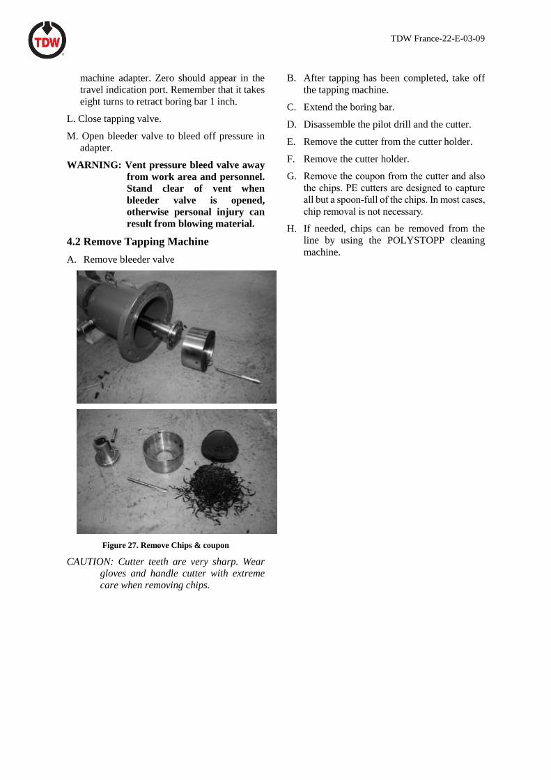
A. Remove bleeder valve
Figure 27. Remove Chips & coupon
CAUTION: Cutter teeth are very sharp. Wear
gloves and handle cutter with extreme
care when removing chips.
B. After tapping has been completed, take off
the tapping machine.
C. Extend the boring bar.
D. Disassemble the pilot drill and the cutter.
E. Remove the cutter from the cutter holder.
F. Remove the cutter holder.
G. Remove the coupon from the cutter and also
the chips. PE cutters are designed to capture
all but a spoon-full of the chips. In most cases,
chip removal is not necessary.
H. If needed, chips can be removed from the
line by using the POLYSTOPP cleaning
machine.

TDW France-22-E-03-09
Section IV: Plugging the Line
1.0 Introduction
This section provides procedures for temporarily plugging 315-355 mm line while work is being performed.
The line may be kept in service during plugging operations by plugging it at two locations to isolate the line
section in between and running a bypass around the isolated area.
2.0 Plugging the Main Line
All parts that makeup the plugging head assembly must be clean and in good condition. Remove all dirt and
any rust scale from all mating surfaces and bolt holes. All internal threads should be inspected for wear, and
a light coating of lubricating oil applied to reduce friction.
If using a plugging machine with a jack, check the drag on the jacking mechanism following the instructions
in Section VI, Maintenance. Make sure this test is done without the sealing element attached.
2.1 Install the Plugging Head
A. Extend the control bar through the plugging head housing and insert the control bar handles in the
handle connectors. Twist the upper handle to disengage the locking pin. Turn the control bar handles
to align the keyways on the lower end of the external and internal bars, as shown in Figure 28.
Figure 28. Align Control Bar Keyways
B. Plugging head halves are shown in Figure 29.
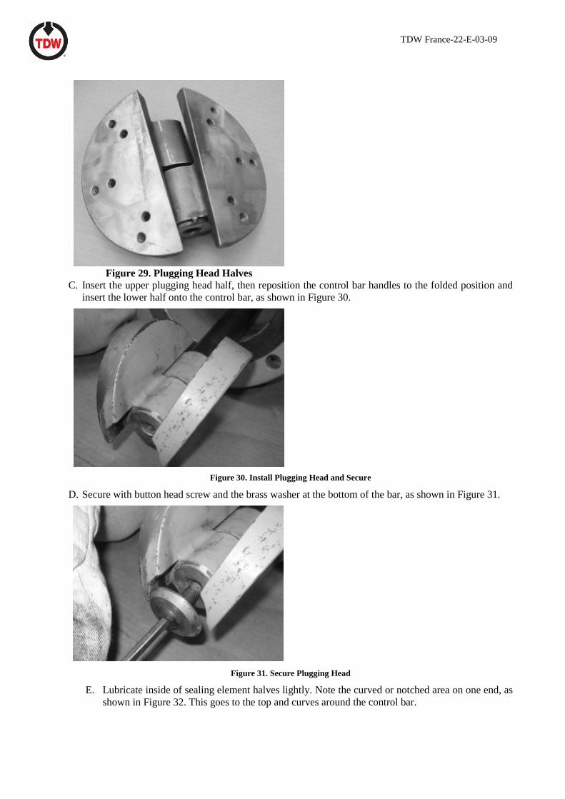
TDW France-22-E-03-09
Figure 29. Plugging Head Halves
C. Insert the upper plugging head half, then reposition the control bar handles to the folded position and
insert the lower half onto the control bar, as shown in Figure 30.
Figure 30. Install Plugging Head and Secure
D. Secure with button head screw and the brass washer at the bottom of the bar, as shown in Figure 31.
Figure 31. Secure Plugging Head
E. Lubricate inside of sealing element halves lightly. Note the curved or notched area on one end, as
shown in Figure 32. This goes to the top and curves around the control bar.
TDW France-22-E-03-09
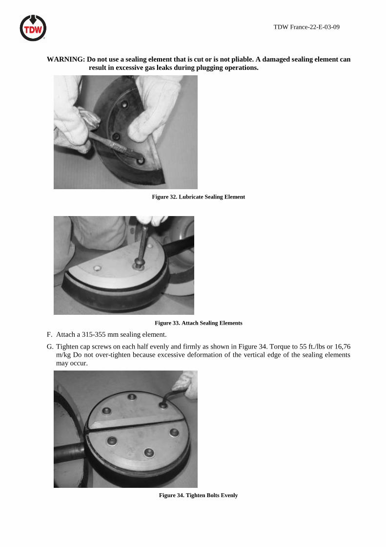
WARNING: Do not use a sealing element that is cut or is not pliable. A damaged sealing element can
result in excessive gas leaks during plugging operations.
Figure 32. Lubricate Sealing Element
Figure 33. Attach Sealing Elements
F. Attach a 315-355 mm sealing element.
G. Tighten cap screws on each half evenly and firmly as shown in Figure 34. Torque to 55 ft./lbs or 16,76
m/kg Do not over-tighten because excessive deformation of the vertical edge of the sealing elements
may occur.
Figure 34. Tighten Bolts Evenly
TDW France-22-E-03-09
E. When both sealing element halves are secure, fully open the folding plugging head until the pin locks
into position. Check to make sure the sealing elements meet across the entire mating surfaces, as shown
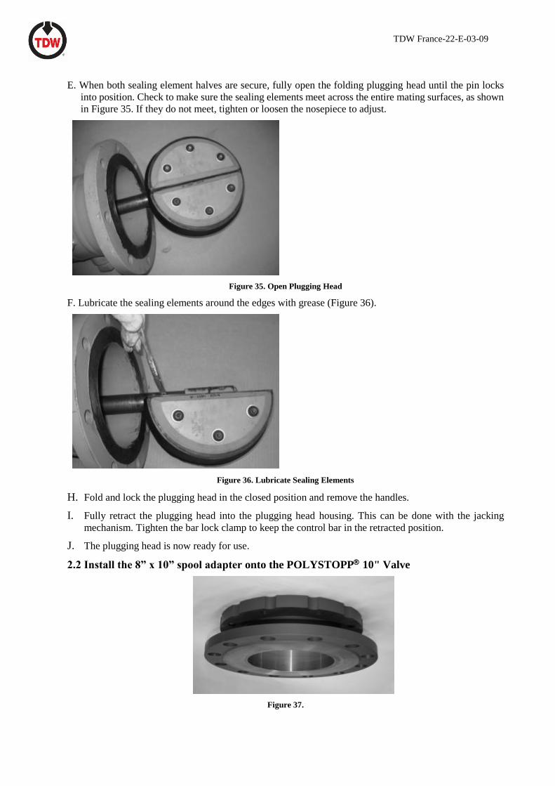
in Figure 35. If they do not meet, tighten or loosen the nosepiece to adjust.
Figure 35. Open Plugging Head
F. Lubricate the sealing elements around the edges with grease (Figure 36).
Figure 36. Lubricate Sealing Elements
H. Fold and lock the plugging head in the closed position and remove the handles.
I. Fully retract the plugging head into the plugging head housing. This can be done with the jacking
mechanism. Tighten the bar lock clamp to keep the control bar in the retracted position.
J. The plugging head is now ready for use.
2.2 Install the 8” x 10” spool adapter onto the POLYSTOPP 10" Valve
Figure 37.
TDW France-22-E-03-09
2.3 Install the Plugging Machine
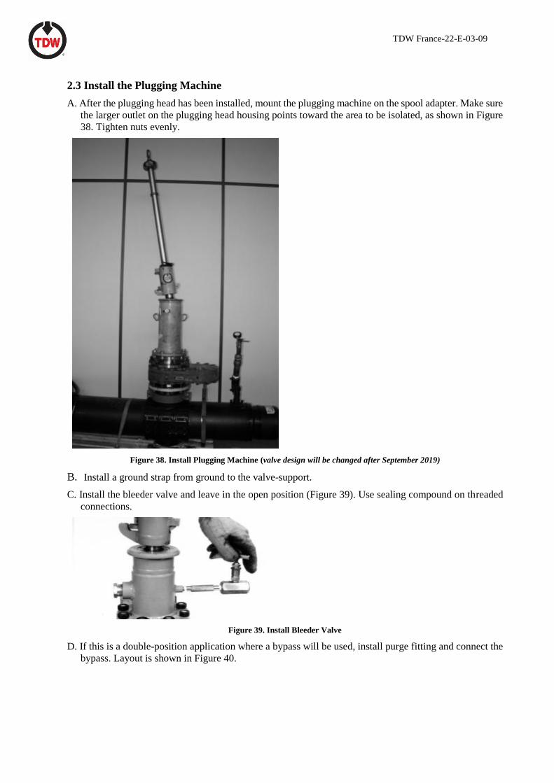
A. After the plugging head has been installed, mount the plugging machine on the spool adapter. Make sure
the larger outlet on the plugging head housing points toward the area to be isolated, as shown in Figure
38. Tighten nuts evenly.
Figure 38. Install Plugging Machine (valve design will be changed after September 2019)
B. Install a ground strap from ground to the valve-support.
C. Install the bleeder valve and leave in the open position (Figure 39). Use sealing compound on threaded
connections.
Figure 39. Install Bleeder Valve
D. If this is a double-position application where a bypass will be used, install purge fitting and connect the
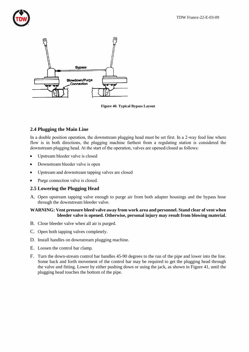
bypass. Layout is shown in Figure 40.
TDW France-22-E-03-09
Figure 40. Typical Bypass Layout
2.4 Plugging the Main Line
In a double position operation, the downstream plugging head must be set first. In a 2-way feed line where
flow is in both directions, the plugging machine farthest from a regulating station is considered the
downstream plugging head. At the start of the operation, valves are opened/closed as follows:
• Upstream bleeder valve is closed
• Downstream bleeder valve is open
• Upstream and downstream tapping valves are closed
• Purge connection valve is closed.
2.5 Lowering the Plugging Head
A. Open upstream tapping valve enough to purge air from both adapter housings and the bypass hose
through the downstream bleeder valve.
WARNING: Vent pressure bleed valve away from work area and personnel. Stand clear of vent when
bleeder valve is opened. Otherwise, personal injury may result from blowing material.
B. Close bleeder valve when all air is purged.
C. Open both tapping valves completely.
D. Install handles on downstream plugging machine.
E. Loosen the control bar clamp.
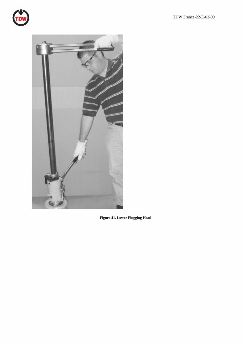
F. Turn the down-stream control bar handles 45-90 degrees to the run of the pipe and lower into the line.
Some back and forth movement of the control bar may be required to get the plugging head through
the valve and fitting. Lower by either pushing down or using the jack, as shown in Figure 41, until the
plugging head touches the bottom of the pipe.
TDW France-22-E-03-09
Figure 41. Lower Plugging Head
TDW France-22-E-03-09
WARNING: Do not stand over the control bar while lowering or raising control bar with the jack.
2.6 Setting the Plugging Head
A. If this is a double position job, set the down- stream plugging head first. Twist the top control bar handle
clockwise to disengage the locking pin. Open handles until the locking pin snaps back into the locked-
open position, as shown in Figure 42. Some "jockeying" of the plugging head, by turning the handles
back and forth and even lowering or raising slightly, may be required as it opens.
Note: Handles may rotate several degrees beyond 180 degrees before locking in the open position.
Figure 42. Open Plugging Head
B. When the handles lock in the open position, turn the plugging head until the arrow on the top handle
connector points to the isolated section of pipe (handles perpendicular to the pipe) and pull back while
slightly turning the handles side to side. This action sets the plugging head in the pipe (Figure 43).
Figure 43. Set the Plugging Head
C. Turn the jack or bar lock mechanism on the control bar to place the control bar latch in the latching
position, opposite from the isolated section. This holds the plugging head in the set position. Set and
tighten the latch as shown in Figure 44.

TDW France-22-E-03-09
Figure 44. Set Control Bar Latch
D. Tighten the control bar clamp (Figure 45). The plugging head is now in a secure position. Remove the
control bar handles.
Figure 45 Tighten Control Bar Clamp
E. If this is a double-position job, set the upstream plugging head. Repeat steps A through D.
F. Bleed off pressure and purge the isolated section. Plugging head(s) are set when pressure in the isolated
section is zero psi (or zero bar), and handles are properly positioned.
G. Snug up the control bar latches, if necessary, after purging.
H. Remove the handles from the plugging machine control bar.
CAUTION: After the plugging head has been set, remove handles from the control bar. Leaving them in
the machine increases the possibility of the plugging head being accidentally dislodged.
I. Purge, cut and perform necessary work.
2.7 Removing the Plugging Head
When removing a double system setup, purge and pressure equalize the isolated section, then remove the
upstream plugging head-first.
TDW France-22-E-03-09
A. Install the control bar handles in the upstream plugging machine.
B. Loosen and unlatch the control bar latch.
C. Slightly loosen the control bar clamp.
D. Turn the control bar to break the plugging head seal.
E. Purge the isolated section.
F. Turn the upper handle to unlock the plugging head, and fold the plugging head by bringing the handles
together. At the same time, turn the plugging head 45 degrees to the run of the pipe.
G. Allow the pin to snap back to lock the folding plugging head in the closed position.
WARNING: Do not stand above plugging machine. Line pressure will tend to force the control bar
upward when the seal is broken. This could cause injury.
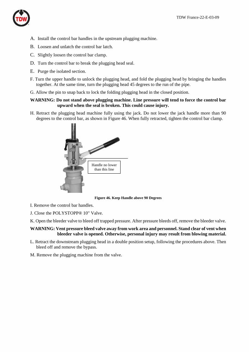
H. Retract the plugging head machine fully using the jack. Do not lower the jack handle more than 90
degrees to the control bar, as shown in Figure 46. When fully retracted, tighten the control bar clamp.
Figure 46. Keep Handle above 90 Degrees
I. Remove the control bar handles.
J. Close the POLYSTOPP® 10" Valve.
K. Open the bleeder valve to bleed off trapped pressure. After pressure bleeds off, remove the bleeder valve.
WARNING: Vent pressure bleed valve away from work area and personnel. Stand clear of vent when
bleeder valve is opened. Otherwise, personal injury may result from blowing material.
L. Retract the downstream plugging head in a double position setup, following the procedures above. Then
bleed off and remove the bypass.
M. Remove the plugging machine from the valve.
Handle no lower
than this line
TDW France-22-E-03-09
Section V: Setting the Completion Plug
with the POLYSTOPP® completion machine
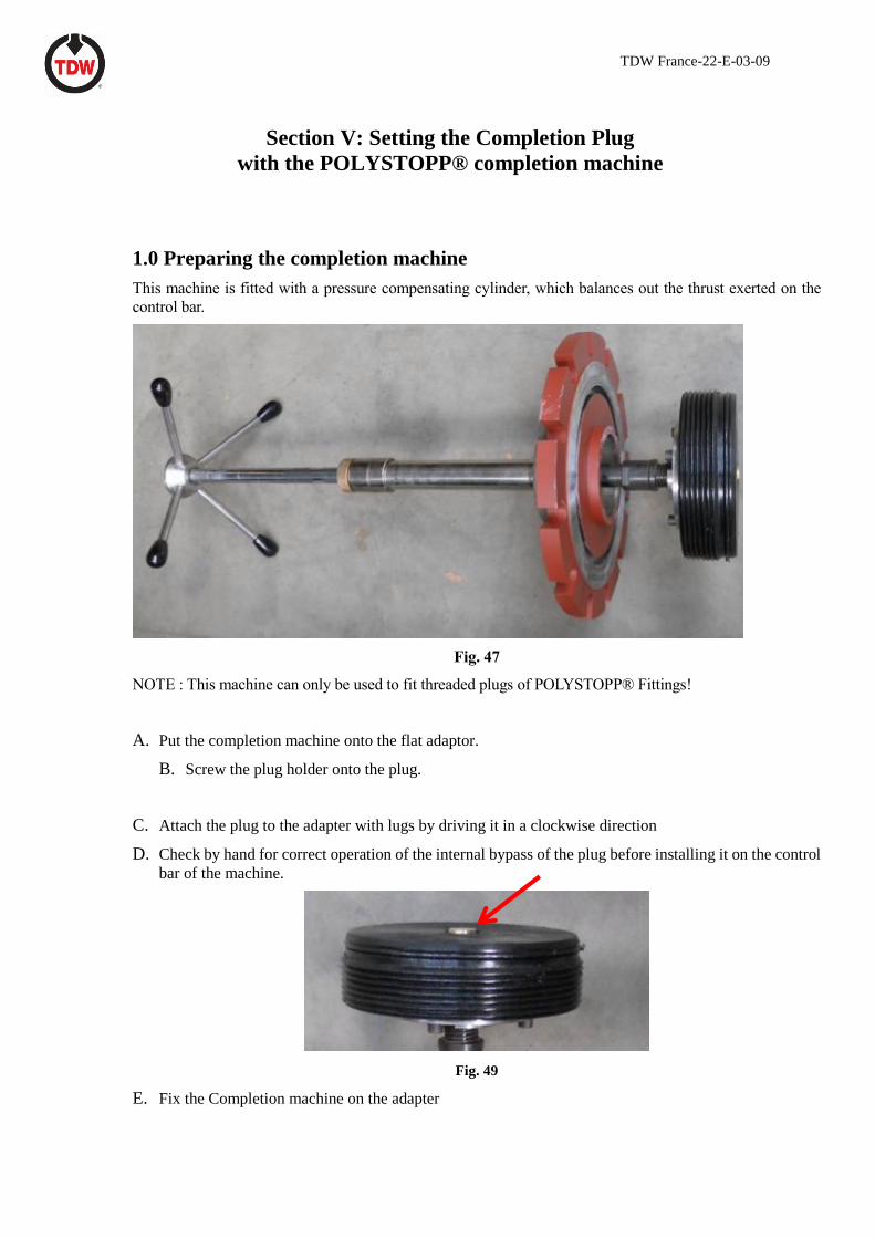
1.0 Preparing the completion machine
This machine is fitted with a pressure compensating cylinder, which balances out the thrust exerted on the
control bar.
Fig. 47
NOTE : This machine can only be used to fit threaded plugs of POLYSTOPP® Fittings!
A. Put the completion machine onto the flat adaptor.
B. Screw the plug holder onto the plug.
C. Attach the plug to the adapter with lugs by driving it in a clockwise direction
D. Check by hand for correct operation of the internal bypass of the plug before installing it on the control
bar of the machine.
Fig. 49
E. Fix the Completion machine on the adapter
TDW France-22-E-03-09
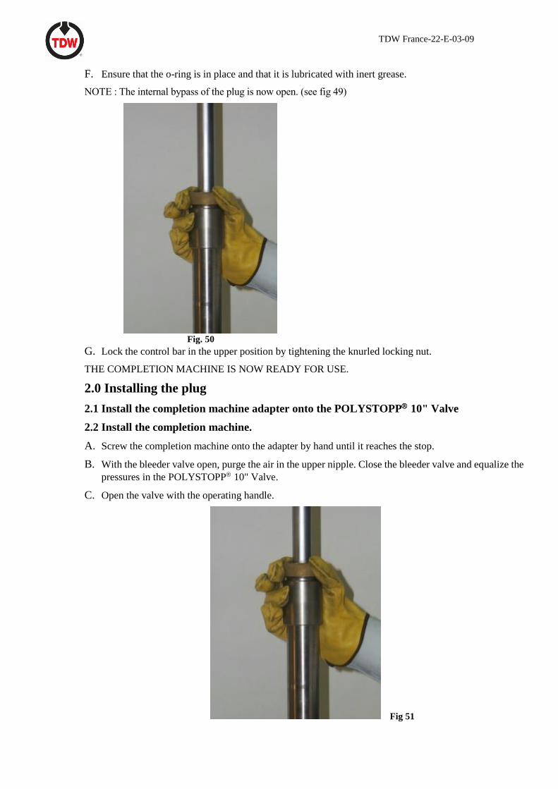
F. Ensure that the o-ring is in place and that it is lubricated with inert grease.
NOTE : The internal bypass of the plug is now open. (see fig 49)
Fig. 50
G. Lock the control bar in the upper position by tightening the knurled locking nut.
THE COMPLETION MACHINE IS NOW READY FOR USE.
2.0 Installing the plug
2.1 Install the completion machine adapter onto the POLYSTOPP 10" Valve
2.2 Install the completion machine.
A. Screw the completion machine onto the adapter by hand until it reaches the stop.
B. With the bleeder valve open, purge the air in the upper nipple. Close the bleeder valve and equalize the
pressures in the POLYSTOPP 10" Valve.
C. Open the valve with the operating handle.
Fig 51
TDW France-22-E-03-09
D. Unlock the control bar with the knurled nut.
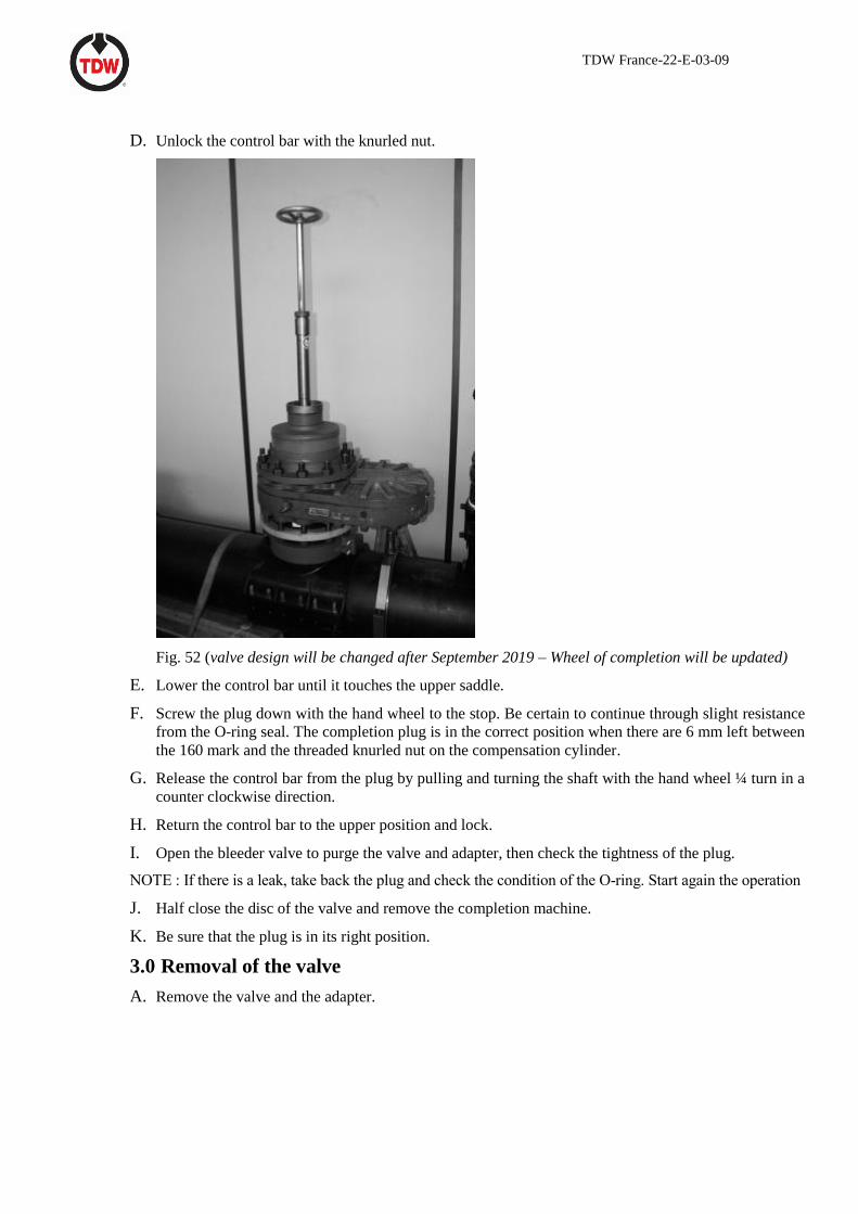
Fig. 52 (valve design will be changed after September 2019 – Wheel of completion will be updated)
E. Lower the control bar until it touches the upper saddle.
F. Screw the plug down with the hand wheel to the stop. Be certain to continue through slight resistance
from the O-ring seal. The completion plug is in the correct position when there are 6 mm left between
the 160 mark and the threaded knurled nut on the compensation cylinder.
G. Release the control bar from the plug by pulling and turning the shaft with the hand wheel ¼ turn in a
counter clockwise direction.
H. Return the control bar to the upper position and lock.
I. Open the bleeder valve to purge the valve and adapter, then check the tightness of the plug.
NOTE : If there is a leak, take back the plug and check the condition of the O-ring. Start again the operation
J. Half close the disc of the valve and remove the completion machine.
K. Be sure that the plug is in its right position.
3.0 Removal of the valve
A. Remove the valve and the adapter.
TDW France-22-E-03-09
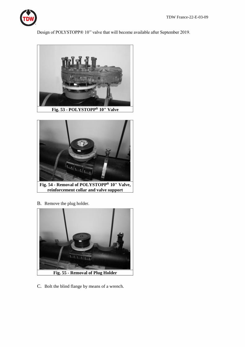
Design of POLYSTOPP® 10’’ valve that will become available after September 2019.
Fig. 53 - POLYSTOPP 10" Valve
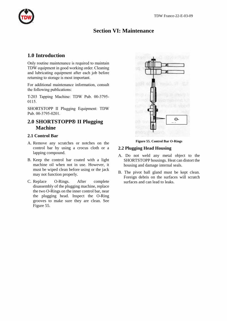
Fig. 54 - Removal of POLYSTOPP 10" Valve,
reinforcement collar and valve support
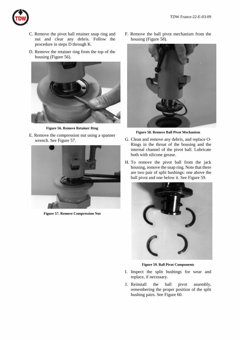
B. Remove the plug holder.
Fig. 55 - Removal of Plug Holder
C. Bolt the blind flange by means of a wrench.
TDW France-22-E-03-09
Section VI: Maintenance
1.0 Introduction
Only routine maintenance is required to maintain
TDW equipment in good working order. Cleaning
and lubricating equipment after each job before
returning to storage is most important.
For additional maintenance information, consult
the following publications:
T-203 Tapping Machine: TDW Pub. 00-3795-
0115.
SHORTSTOPP II Plugging Equipment: TDW
Pub. 00-3795-0201.
2.0 SHORTSTOPP II Plugging
Machine
2.1 Control Bar
A. Remove any scratches or notches on the
control bar by using a crocus cloth or a
lapping compound.
B. Keep the control bar coated with a light
machine oil when not in use. However, it
must be wiped clean before using or the jack
may not function properly.
C. Replace O-Rings. After complete
disassembly of the plugging machine, replace
the two O-Rings on the inner control bar, near
the plugging head. Inspect the O-Ring
grooves to make sure they are clean. See
Figure 55.
Figure 55. Control Bar O-Rings
2.2 Plugging Head Housing
A. Do not weld any metal object to the
SHORTSTOPP housings. Heat can distort the
housing and damage internal seals.
B. The pivot ball gland must be kept clean.
Foreign debris on the surfaces will scratch
surfaces and can lead to leaks.
O-
Rings
TDW France-22-E-03-09
C. Remove the pivot ball retainer snap ring and
nut and clear any debris. Follow the
procedure in steps D through K.
D. Remove the retainer ring from the top of the
housing (Figure 56).
Figure 56. Remove Retainer Ring
E. Remove the compression nut using a spanner
wrench. See Figure 57.
Figure 57. Remove Compression Nut
F. Remove the ball pivot mechanism from the
housing (Figure 58).
Figure 58. Remove Ball Pivot Mechanism
G. Clean and remove any debris, and replace O-
Rings in the throat of the housing and the
internal channel of the pivot ball. Lubricate
both with silicone grease.
H. To remove the pivot ball from the jack
housing, remove the snap ring. Note that there
are two pair of split bushings: one above the
ball pivot and one below it. See Figure 59.
Figure 59. Ball Pivot Components
I. Inspect the split bushings for wear and
replace, if necessary.
J. Reinstall the ball pivot assembly,
remembering the proper position of the split
bushing pairs. See Figure 60.
TDW France-22-E-03-09
Figure 60. Reinstall Ball Pivot Assembly
K. When reinstalling the compression nut, snug
lightly then install the retainer ring.
2.3 Control Bar Lock/Jack
Occasionally, it is necessary to remove the control
bar jack system for lubrication or maintenance, or
for use on another housing. Remove as follows:
A. Remove the plugging head from the control
bar, and remove the control bar from the
housing.
B. Disassemble and clean all jack components
then reinstall them dry. No lubricant is
necessary and may, in fact, attract
contaminants.
C. Remove the ball pivot assembly, following the
procedures in paragraph 3.2 above.
D. The Belleville washers must be stacked in a
series, i.e. OD to OD and ID to ID. The lower
washer starts with the ID down.
E. Note size of flat spot wear on upper and lower
actuators. These actuators should be replaced
when the small flat spots that develop with
use exceed .045 inches. See Figure 61.
Figure 62. Inspect Actuators for Wear
F. Reinstall the jack or control bar lock unit on
the ball pivot of the plugging housing.
2.4 Adjusting Jack System Drag
A. The jack system drag needs to be checked
prior to each job with the plugging head,
without the sealing element, attached.
Continual adjustments may be required in
the field as components wear or break.
B. Additional drag can be created by advancing
the drag adjust set screw (Figure 62).
Turning the adjustment clockwise increases
the tension while counterclockwise turning
decreases it.
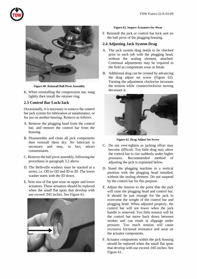
Figure 62. Drag Adjust Set Screw
C. Do not over-tighten as jacking effort may
become difficult. Too little drag may allow
the control bar to rise suddenly under higher
pressures. Recommended method of
adjusting the jack is explained below.
D. Stand the plugging machine in a vertical
position with the plugging head installed,
without the sealing element. Do not suspend
by the control bar for this purpose.
E. Adjust the tension to the point that the jack
will raise the plugging head and control bar.
It should be just enough for the jack to
overcome the weight of the control bar and
plugging head. When adjusted properly, the
control bar will not lower when the jack
handle is removed. Too little tension will let
the control bar move back down between
strokes and can result in slippage under
pressure. Too much tension will cause
excessive frictional resistance and wear on
the actuator components.
F. Actuator components within the jack housing
should be replaced when the small flat spots
that develop with use exceed .045 inches. See
Figure 61.
TDW France-22-E-03-09
3.0 POLYSTOPP Completion
Machine
3.1 Disassembly Procedures
On a clean workbench with easy access, the
disassembly and assembly should be carried out in
the order given below,, using a 6 Ø pin punch and
a hammer.
A. Remove the plug holder from the control bar
by removing the flexible pin.
B. Remove the hand wheel from the control bar
using a 24 mm spanner. The remove the key
from the end of the control bar.
C. Remove the head of the compensating
cylinder, the knurled locking nut , the
locking ring with the two stops.
D. Remove the control bar from the pressure
compensating cylinder.
3.2 Maintenance of the completion
machine
A. When the completion machine has been
completely disassembled, replace all the
following O-rings.
B. Inspect the cover. Carefully clean the cover,
the inside, the outer thread and the O-ring
grooves.
C. Protect the surfaces. Use a light oil,
compatible with the substance in which the
completion machine is to operate.
3.3 Reassembling the completion machine
After dismantling and maintenance, reassemble in
the following order.
A. The control bar : Insert the bar into the
compensating cylinder.
B. When the completion machine has been
completely disassembled, replace all the
following O-rings.
CAUTION : Take care not to damage the O-ring.
C. Install the compensating cylinder head with
all tits components (washer + locking ring).
D. Install the hand wheel with the key.
E. Screw the plug holder on the control bar and
drive again the flexible pin.
4.0 SHORTCUTT Valve
The SHORTCUTT® Valve is relatively
maintenance-free. Any component can be
replaced easily. A parts list and assembly diagram
are shown below.
When not in use, the valve should be stored with
the disc closed. A light coating of oil should be
applied to the disc prior to storing.
5.1 Disassembly and Inspection
The valve should be disassembled and inspected
every 30 days during continued use and at least
annually when occasionally used.
A. Inspect and lubricate bearings, the operating
stem, and bypass valve stem.
B. If replacing the thrust collar/bearing (item 24
in Parts List No. 1), delete the item 28 thrust
washer and replace with the extra washer
furnished with the 00-1014-0007-01 bearing,
as shown in Figure 63.
Figure 63. Replacing Thrust Collar/Bearing
TDW France-22-E-03-09
Table 1
Thrust Collar/Bearing
Ite
m
Qty. Description Part Number
1 1 Thrust Bearing 00-7447-002
2 1 Thrust Washer 0-6813-0001
3 2 Thrust Washer 00-6813-0002
1. Replacement Bearing 00-1014-
0007-01 re-places Bearing 00-1014-0007
and Thrust Washer 00-1407-0001.
2. The 00-1014-0007 thrust bearing
used prior to January 1994 has been
discontinued by the bearing
manufacturer, with no direct replacement
available. Because of the size similarity
of the new bearing’s thrust washers and
the old 00-1407-0001 thrust washer, it is
necessary to discard the old, softer, thrust
washer and use the new, harder, thrust
washer to ensure the softer one does not
become a bearing race.
C. Inspect all O-rings and replace if cut, cracked,
flattened, or hardened.
D. A retaining plate, shown in View B of the
assembly drawing, prevents the operating
stem from backing out of the valve if properly
operated. It must be removed to replace the
stem O-ring. When reinstalling this plate,
torque the two hex-head bolts holding it to the
following values:
Table 2
Cap Screw Torque Values
Size Torque Range
10" 250-350 in. lbs
E. Socket stud nuts and hex-head bolts holding
the two side plates together should be torqued
to the following values:
Table 3
Stud Torque Values
Size Minimum Maximum
10" 170 ft lbs. 222 ft lbs.
TDW France-22-E-03-09
Appendix I: Parts Lists
Parts List No. 1
POLYSTOPP System for PE Pipes Big Sizes
315-355 mm
Description Part Number
T-203 Drilling Machine 12303981
SHORTSTOPP Plugging Machine
8 x 12
08.3501081.0000.00
POLYSTOPP Completion Machine
75.0537.0100.0400.10
POLYSTOPP 10" Valve
TBD
TDW France-22-E-03-09
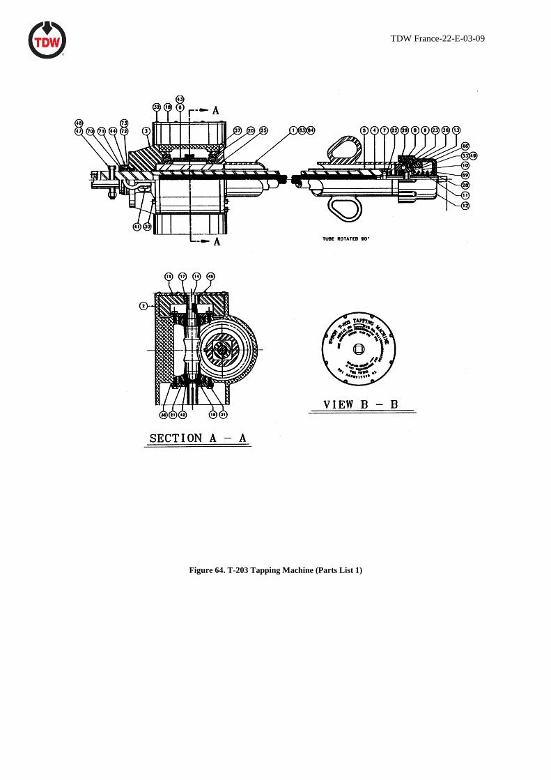
Figure 64. T-203 Tapping Machine (Parts List 1)

TDW France-22-E-03-09
Parts List 2
T-203 Tapping Machine
Item Description Part Number
Air Drive
Tapping Machine 05-2173-0000
1 Body Tube 05-0261-0001
2 Gear Case 05-0222-0002
3 Seal Gland 05-0261-0003
4 Boring Bar 05-0353-0004
5 Drive Tube 06-0261-0005
6 Worm Gear 00-1663-0001
7 Feed Screw 05-0261-0007
8 Feed Ball Race 05-2171-0008
9 Feed Ball Drive Plate 05-2171-0009
10 Cam Feed Plate 05-2171-0010
11 Feed Adjuster 05-2171-0011
12 Feed Adjusting Cap 05-2171-0012
13 Feed Assist Spring 00-0136-0170
14 Worm 05-0261-0014
15 Flywheel 05-0222-0015
16 Worm Bearing Retainer 05-0261-0016
17 Taper-Lock Bushing 00-1641-0003
18 Flywheel Cover 05-0972-0018
19 Lower-in Crank (not shown) 00-0635-0002
20 Worm Gear Bearing 00-0124-0013
21 Worm Shaft Bearing 00-0124-0014
22 Thrust Bearing 00-1014-0014
23 Steel Ball 00-0460-0005
25 O-ring 00-0118-0018
28 Oil Seal 00-2683-0001
29 O-ring 00-0117-0016
30 Socket Head Cap Screw 00-0130-0600-10
31 Bolt 00-0203-0600-08
32 Button Head Screw 00-3336-1000-16
33 Light Thin ESNA Nut 00-0232-0010
36 Dowel Pin 00-0854-0002
37 Gear Case Shim Set 00-0800-0002
38 Worm Shaft Shim Set 00-0798-0002
39 Relief Fitting (not shown) 00-1665-0001

TDW France-22-E-03-09
Parts List 3
T-203 Tapping Machine (Continued)
Item Description Part Number
Air Drive
40 Pipe Bushing (not shown) 00-0644-0002
41 Anchor Shackle with Round Pin 00-1666-0001
42 Seal 00-0114-0038
43 Square Key 00-0642-0007
44 O-ring 00-0118-0002
45 Square Key 00-0640-0004
46 Square Key 00-0639-0014
47 Shoulder Screw 00-0204-01000-22
48 ESNA Nut 00-0003-0005
49 Spring Washer 00-5753-0001
50 Bleeder Valve (not shown) 00-0774-0001
51 Nipple (not shown) 00-0220-0001
52 Square Key 00-0640-0002
53 Bolt 00-0203-1000-10
54 Boring Bar Protector (not shown) 05-0222-0054
66 Hex Socket Plug 00-0018-0005
69 Feed Adjusting Spring 00-0136-0169
70 Packing Nut 05-0222-0070
71 Packing spring 00-0136-0033
72 Packing Washer 05-0222-0072
73 Packing 00-1768-0001
74 Packing Nut Wrench (not shown) 00-1767-0001
83 Caution Decal 00-3302-0003
84 Danger Decal 00-3303-0001
85 Instruction Manual 00-3795-0115
TDW France-22-E-03-09
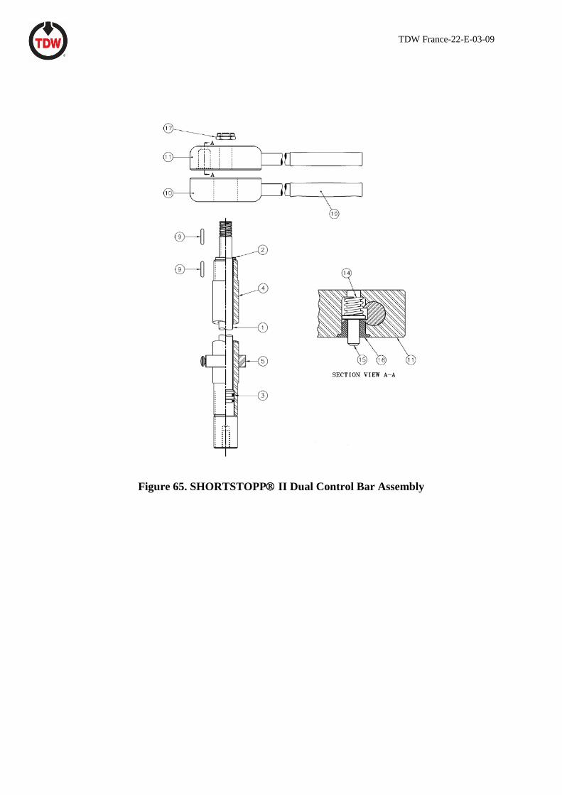
Figure 65. SHORTSTOPP II Dual Control Bar Assembly
TDW France-22-E-03-09
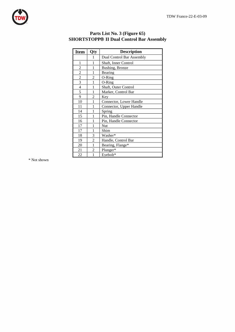
Parts List No. 3 (Figure 65)
SHORTSTOPP II Dual Control Bar Assembly
Item Qty Description
1 Dual Control Bar Assembly
1 1 Shaft, Inner Control
2 1 Bushing, Bronze
2 1 Bearing
2 2 O-Ring
3 1 O-Ring
4 1 Shaft, Outer Control
5 1 Marker, Control Bar
9 2 Key
10 1 Connector, Lower Handle
11 1 Connector, Upper Handle
14 1 Spring
15 1 Pin, Handle Connector
16 1 Pin, Handle Connector
17 1 Nut
17 1 Shim
18 3 Washer*
19 2 Handle, Control Bar
20 1 Bearing, Flange*
21 2 Plunger*
22 1 Eyebolt*
* Not shown

TDW France-22-E-03-09
Figure 66. SHORTSTOPPII Jack Assembly
TDW France-22-E-03-09
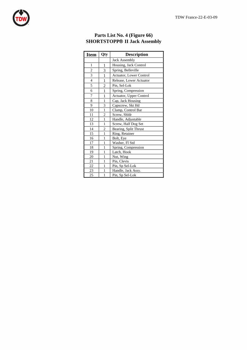
Parts List No. 4 (Figure 66)
SHORTSTOPP II Jack Assembly
Item Qty Description
Jack Assembly
1 1 Housing, Jack Control
2 3 Spring, Belleville
3 1 Actuator, Lower Control
4 1 Release, Lower Actuator
5 2 Pin, Sel-Lok
6 1 Spring, Compression
7 1 Actuator, Upper Control
8 1 Cap, Jack Housing
9 3 Capscrew, Skt Hd
10 1 Clamp, Control Bar
11 2 Screw, Shldr
12 1 Handle, Adjustable
13 1 Screw, Half Dog Set
14 2 Bearing, Split Thrust
15 1 Ring, Retainer
16 1 Bolt, Eye
17 1 Washer, Fl Std
18 1 Spring, Compression
19 1 Latch, Hook
20 1 Nut, Wing
21 1 Pin, Clevis
22 1 Pin, Sp Sel-Lok
23 1 Handle, Jack Assy.
25 1 Pin, Sp Sel-Lok
TDW France-22-E-03-09
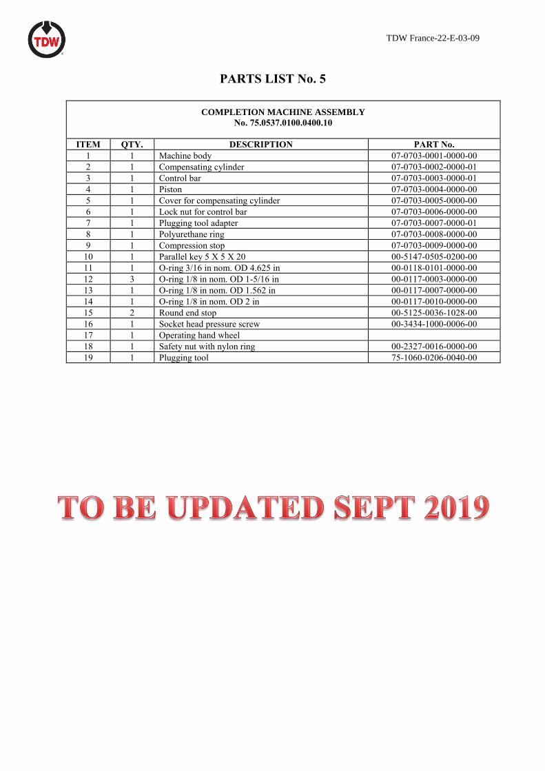
PARTS LIST No. 5
COMPLETION MACHINE ASSEMBLY
No. 75.0537.0100.0400.10
ITEM QTY. DESCRIPTION PART No.
1 1 Machine body 07-0703-0001-0000-00
2 1 Compensating cylinder 07-0703-0002-0000-01
3 1 Control bar 07-0703-0003-0000-01
4 1 Piston 07-0703-0004-0000-00
5 1 Cover for compensating cylinder 07-0703-0005-0000-00
6 1 Lock nut for control bar 07-0703-0006-0000-00
7 1 Plugging tool adapter 07-0703-0007-0000-01
8 1 Polyurethane ring 07-0703-0008-0000-00
9 1 Compression stop 07-0703-0009-0000-00
10 1 Parallel key 5 X 5 X 20 00-5147-0505-0200-00
11 1 O-ring 3/16 in nom. OD 4.625 in 00-0118-0101-0000-00
12 3 O-ring 1/8 in nom. OD 1-5/16 in 00-0117-0003-0000-00
13 1 O-ring 1/8 in nom. OD 1.562 in 00-0117-0007-0000-00
14 1 O-ring 1/8 in nom. OD 2 in 00-0117-0010-0000-00
15 2 Round end stop 00-5125-0036-1028-00
16 1 Socket head pressure screw 00-3434-1000-0006-00
17 1 Operating hand wheel
18 1 Safety nut with nylon ring 00-2327-0016-0000-00
19 1 Plugging tool 75-1060-0206-0040-00
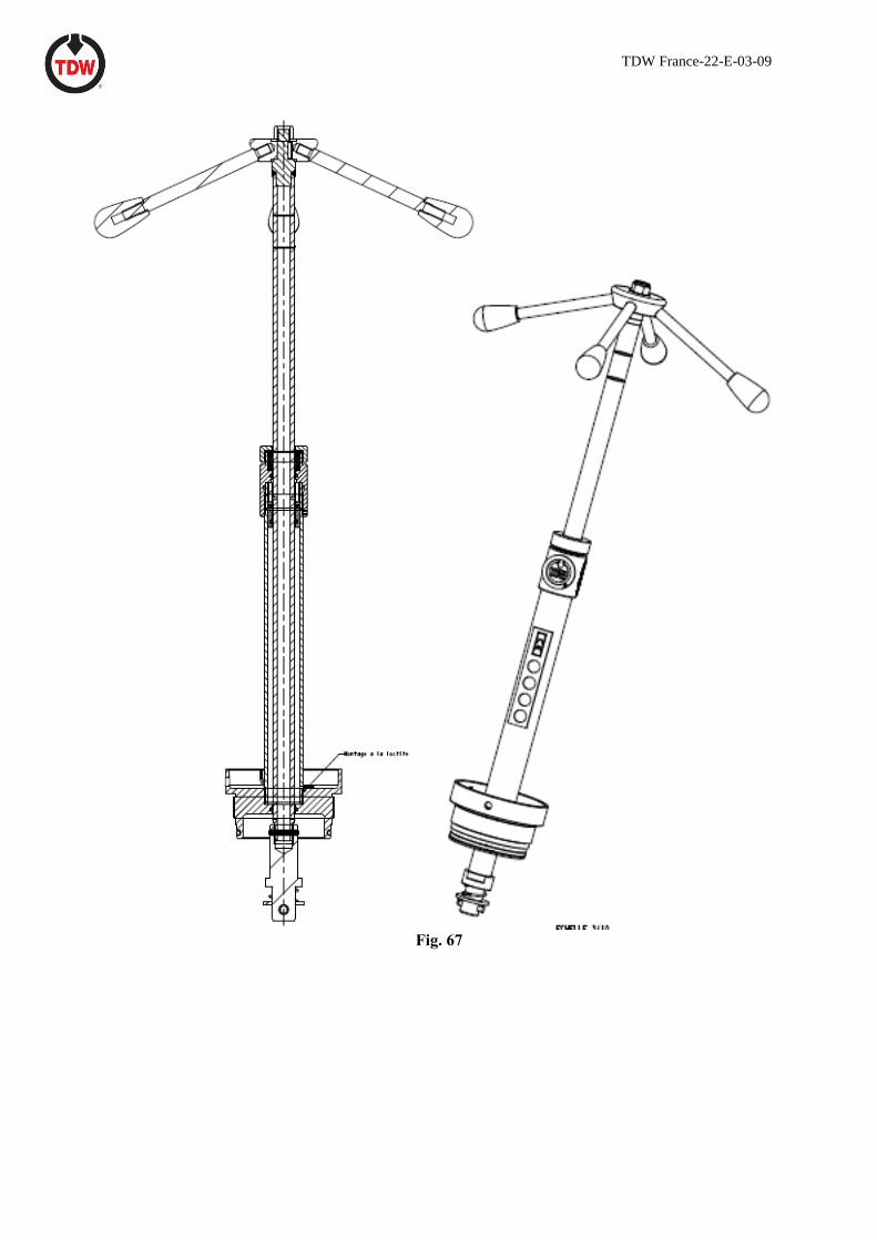
TDW France-22-E-03-09
Fig. 67

TDW France-22-E-03-09
Parts List No. 7 POLYSTOPP® Valve, 10"
(See Figure 68)
TO BE ADDED UPON NEW DESIGN VALVE LAUNCHING

TDW France-22-E-03-09
TO BE ADDED UPON NEW DESIGN VALVE LAUNCHING
Fig. 68
TDW France-22-E-03-09
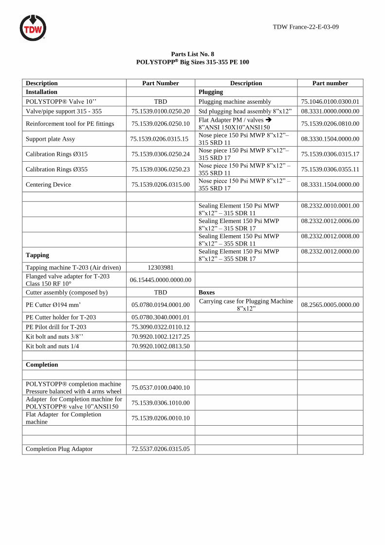
Parts List No. 8
POLYSTOPP Big Sizes 315-355 PE 100
Description Part Number Description Part number
Installation Plugging
POLYSTOPP® Valve 10’’ TBD Plugging machine assembly 75.1046.0100.0300.01
Valve/pipe support 315 - 355 75.1539.0100.0250.20 Std plugging head assembly 8”x12” 08.3331.0000.0000.00
Reinforcement tool for PE fittings 75.1539.0206.0250.10 Flat Adapter PM / valves ➔
8”ANSI 150X10”ANSI150 75.1539.0206.0810.00
Support plate Assy 75.1539.0206.0315.15 Nose piece 150 Psi MWP 8”x12”–
315 SRD 11 08.3330.1504.0000.00
Calibration Rings Ø315 75.1539.0306.0250.24 Nose piece 150 Psi MWP 8”x12”–
315 SRD 17 75.1539.0306.0315.17
Calibration Rings Ø355 75.1539.0306.0250.23 Nose piece 150 Psi MWP 8”x12” –
355 SRD 11 75.1539.0306.0355.11
Centering Device 75.1539.0206.0315.00 Nose piece 150 Psi MWP 8”x12” –
355 SRD 17 08.3331.1504.0000.00
Sealing Element 150 Psi MWP
8”x12” – 315 SDR 11
08.2332.0010.0001.00
Sealing Element 150 Psi MWP
8”x12” – 315 SDR 17
08.2332.0012.0006.00
Sealing Element 150 Psi MWP
8”x12” – 355 SDR 11
08.2332.0012.0008.00
Tapping Sealing Element 150 Psi MWP
8”x12” – 355 SDR 17
08.2332.0012.0000.00
Tapping machine T-203 (Air driven) 12303981
Flanged valve adapter for T-203
Class 150 RF 10° 06.15445.0000.0000.00
Cutter assembly (composed by) TBD Boxes
PE Cutter Ø194 mm’ 05.0780.0194.0001.00 Carrying case for Plugging Machine
8”x12” 08.2565.0005.0000.00
PE Cutter holder for T-203 05.0780.3040.0001.01
PE Pilot drill for T-203 75.3090.0322.0110.12
Kit bolt and nuts 3/8’’ 70.9920.1002.1217.25
Kit bolt and nuts 1/4 70.9920.1002.0813.50
Completion
POLYSTOPP® completion machine
Pressure balanced with 4 arms wheel 75.0537.0100.0400.10
Adapter for Completion machine for
POLYSTOPP® valve 10”ANSI150 75.1539.0306.1010.00
Flat Adapter for Completion
machine 75.1539.0206.0010.10
Completion Plug Adaptor 72.5537.0206.0315.05

T.D. Williamson (France) S.A.S. 11, Rue de l’Atome – ZI - BP 50081
67802 – Bischheim Cedex Phone. +33 (0)3 88 19 72 38 – Fax +33 (0)3 88 19 72 19
E-mail : [email protected]
Visit TDW’s website at :
www.tdwilliamson.com
TDWFrance Pub. 22-E-03-09 MAY 2019 © Copyright 2019
All rights reserved
T.D. Williamson (France) S.A.S