Embed Size (px)
Citation preview
88 TRANSPORTATION RESEARCH RECORD 1231
Polyethylene Pipe Under High Fill
DANIEL N. ADAMS, TENNYSON MurNDI, AND ERNEST T. SELIG
Because little field performance experience was available for highdensity polyethylene pipe under high earth load, a test installation was carried out with a 24-in.-diameter (610 mm) pipe placed beneath a 100-ft-high (30.5 m) embankment. The pipe was corrugated; and in some sections, a smooth interior wall was added. The pipe was embedded in a shallow trench near the base of the embankment and backfilled with compacted crushed limestone. Instruments were used to measure pipe wall strain, pipe diameter change, earth pressure acting on the pipe, vertical soil strain adjacent to the pipe, and pipe wall temperature. The paper presents results obtained with 95 ft (29 m) of fill over the pipe. No material distress was observed. The pipe remained relatively round, with about 4 percent vertical diameter decrease and 0.4 percent horizontal diameter increase. The average compression strain at the springline was 1.2 percent, and the bending strain was 0.3 percent. The vertical deflection was primarily the result of a 1.4 percent circumference shortening. This shortening resulted in substantial positive arching-measured earth pressure on the pipe crown was only about 20 percent of the vertical embankment earth pressure.
A field study was undertaken to evaluate the performance of a 24-in.-inside-diameter (610 mm) corrugated polyethylene pipe to be loaded by a 100-ft-high (30.5 m) embankment. The embankment is part of the extension of Interstate 279, north of Pittsburgh, Pennsylvania.
The pipe used in this study was manufactured by Advanced Drainage Systems, Inc., of Columbus, Ohio. The pipe has an inside diameter of 24 in. (610 mm); the wall corrugations are 1.6 in. (41 mm) deep; and the wall is 0.22 in. (5.6 mm) thick. The pipe is extruded in 20-ft ( 6.1 m) sections, with the corrugations set on a 7-deg pitch , longitudinally. The joints were connected with wraparound fittings. In some of the pipe sections, a smooth interior wall was adqed (designated N-12). Both types of pipe had a minimum stiffness of 34 psi (235 kPa) in accordance with standard specifications (AASHTO M294-86) .
In this paper, the field investigation is described and the main experimental results obtained during construction of the embankment up to a fill height of 95 ft (29 m) are presented. Further details are available in a research report (1).
FIELD MEASUREMENTS
The following field measurements were made to determine pipe performance:
• Vertical soil strain-Three inductance coils of 12-in. diameter (305 mm) were placed in the embankment to mea-
D. N. Adams and T. Muindi, Haley & Aldrich, Inc., 58 Charles St., Cambridge , Mass. 02141. E. T . Selig, University of Massachusetts, Marston Hall, Amherst, Mass. 01003 .
sure vertical compression of the earth fill at the elevation of the pipe. A pair of coils was also placed in the trench encompassing the pipe to measure vertical compression of the pipe from the outside.
• Pipe wall strain-Three inductance coils of 1-in. diameter (25 mm) were fastened to the pipe wall at the springline to measure bending and compression strains in the pipe wall.
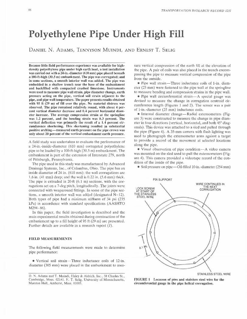
• Pipe wall circumferential strain-A special gauge was devised to measure the change in corrugation centroid circumference length (Figures 1 and 2) . The sensor was a pair of 1-in.-diameter (25 mm) inductance coils .
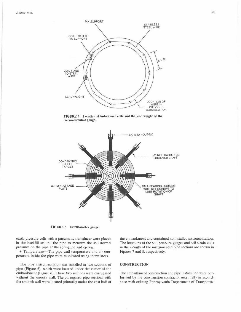
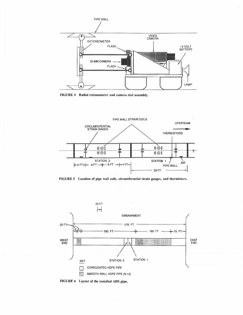
• Internal diameter change-Radial extensometers (Figure 3) were constructed to measure the change in pipe diameter in four directions (vertical, horizontal, and both 45° diagonals). This device was attached to a sled and pulled through the pipe (Figure 4). A 35-mm camera with flash lighting was used to photograph the extensometer arms against a target to provide a record of the movement at selected locations along the pipe.
• Visual observation of pipe condition-A video camera was mounted on the sled used to pull the extensometers (Figure 4) . This camera provided a videotape record of the condition of the inside of the pipe.
• Soil pressure on pipe-Oil-filled 10-in.-diameter (254 mm)
PIN SUPPORT
WIRE CONTINUED IN THE NEXT
CORRUGATION
STAINLESS STEEL WIRE
FIGURE 1 Locauon of pins and stainless steel wire for the circumferential gauge in the pipe helical corrugation.
Adams el al.
PIN SUPPORT
COIL FIXED TO PIN SUPPORT
LEAD WEIGHT
STAINLESS STEEL WIRE
LOCATION OF WIRE IN
PREVIOUS CORRUGATION
89
FIGURE 2 Location of inductance coils and the lead weight of the circumferential gauge.
FIGURE 3 Extensometer gauge.
earth pressure cells with a pneumatic transducer were placed in the backfill around the pipe to measure the soil normal pressure on the pipe at the springline and crown.
• Temperature-The pipe wall temperature and air temperature inside the pipe were monitored using thermistors .
The pipe instrumentation was installed in two sections of pipe (Figure 5), which were located under the center of the embankment (Figure 6). These two sections were corrugated without the smooth wall. The corrugated pipe sections with the smooth wall were located primarily under the east half of
1/2 INCH HARDENED ~--- GROOVED SHAFT
BALL-BEARING HOUSING WITH SET SCREWS TO
LIMIT ROTATION OF SHAFT
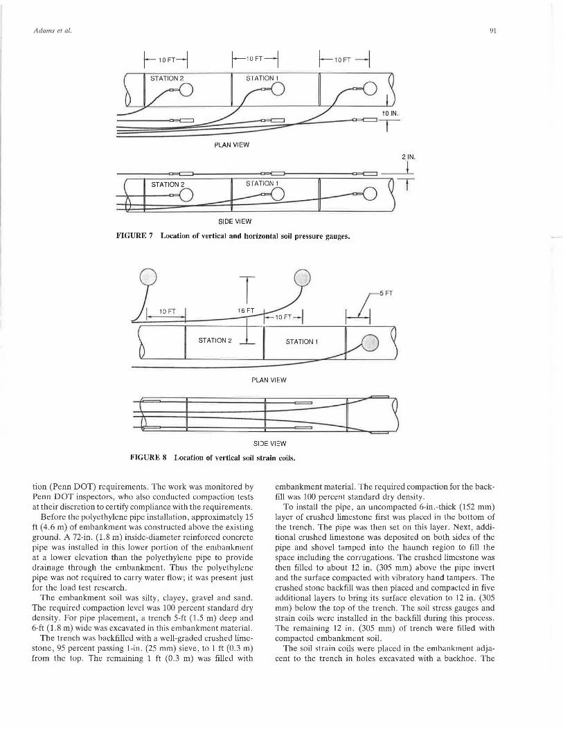
the embankment and contained no installed instrumentation. The locations of the soil pressure gauges and soil strain coils in the vicinity of the instrumented pipe sections are shown in Figures 7 and 8, respectively.
CONSTRUCTION
The embankment construction and pipe installation were performed by the construction contractor essentially in accordance with existing Pennsylvania Department of Transporta-
PIPE WALL
VIDEO CAMERA
35 MM CAMERA -
FIGURE 4 Radial extensometer and camera sled assembly.
CIRCUMFERENTIAL STRAIN GAGES
PIPE WALL STRAIN COILS
e0a e0a
12 VOLT BATTERY
LAMP
UPSTREAM
THERMISTORS
STATION 2 STATION 1
j--4 FT+ 6 FT-+ 6 FT -f-4FT-I----- PIPE WALL
20FT
FIGURE 5 Location of pipe wall coils, circumferential strain gauges, and thermistors.
WEST END
)
20 FT
H EMBANKMENT
KEY
I STATION 2
D CORRUGATED HOPE PIPE
D SMOOTH WALL HOPE PIPE (N-12)
\ STATION 1
FIGURE 6 Layout of the installed ADS pipe.
180 FT I 76 FT-
l EAST END
Adams er al . 91
f- 10FT-1 l--10FT--1 j--10FT --l
PLAN VIEW
2 IN.
l
AZD-B~T SIDE VIEW
FIGURE 7 Location of vertical and horizontal soil pressure gauges.
9 T 5FT
~)i~_1o=FT 2======16[:_FT -1DFT-I ~ b STATION 2 i I STATION' J/O ~
PLAN VIEW
j SI DE VIEW
FIGURE 8 Location of vertical soil strain coils.
tion (Penn DOT) requirements. The work was monitored by Penn DOT inspectors, who also conducted compaction tests at their discretion to certify compliance with the requirements.
Before the polyethylene pipe installation, approximately 15 ft ( 4.6 m) of embankment was constructed above the existing ground. A 72-in. (1.8 m) inside-diameter reinforced concrete pipe was installed in this lower portion of the embankment at a lower elevation than the polyethylene pipe to provide drainage through the embankment. Thus the polyethylene pipe was not required to carry water flow; it was present just for the load test research.
The embankment soil was silty, clayey, gravel and sand. The required compaction level was 100 percent standard dry density . For pipe placement, a trench 5-ft (1.5 m) deep and 6-ft (1.8 m) wide was excavated in this embankment material.
The trench was backfilled with a well-graded crushed limestone , 95 percent passing 1-in. (25 mm) sieve, to 1 ft (0.3 m) from the top. The remaining 1 ft (0.3 m) was filled with
embankment material. The required compaction for the backfill was 100 percent standard dry density.
To install the pipe, an uncompacted 6-in.-thick (152 mm) layer of crushed limestone first was placed in the bottom of the trench. The pipe was then set on this layer. Next, additional crushed limestone was deposited on both sides of the pipe and shovel tamped into the haunch region to fill the space including the corrugations. The crushed limestone was then filled to about 12 in. (305 mm) above the pipe invert and the surface compacted with vibratory hand tampers. The crushed stone backfill was then placed and compacted in five additional layers to bring its surface elevation to 12 in . (305 mm) below the top of the trench. The soil stress gauges and strain coils were installed in the backfill during this process . The remaining 12 in. (305 mm) of trench were filled with compacted embankment soil.
The soil strain coils were placed in the embankment adjacent to the trench in holes excavated with a backhoe. The
92
holes were refilled with embankment material compacted using vibratory hand tampers.
To complete the embankment, an additional 7.5 ft (2.3 m) of silty, clayey, gravel and sand were placed and compacted, bringing the fill height to 10 ft (3 m) above the pipe crown. The next 85 ft (26 m) of embankment was constructed of blasted rock fill, placed and compacted in layers not exceeding 3 ft (0.9 m) thick. The rock composition included shale and sandstone.
RESULTS
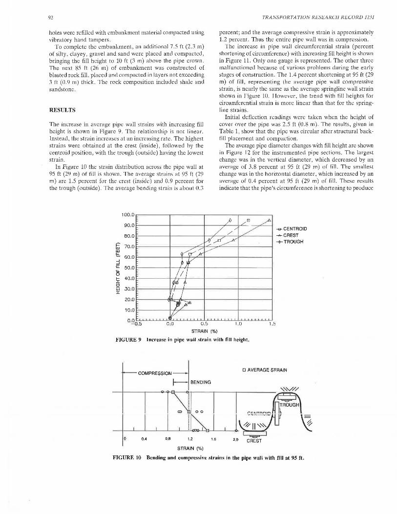
The increase in average pipe wall strains with increasing fill height is shown in Figure 9. The relationship is not linear. Instead, the strain increases at an increasing rate. The highest strains were obtained at the crest (inside), followed by the centroid position, with the trough (outside) having the lowest strain.
In Figure 10 the strain distribution across the pipe wall at 95 ft (29 m) of fi!! is shown. The average strains at 95 ft (29 m) are 1.5 percent for the crest (inside) and 0.9 percent for the trough (outside). The average bending strain is about 0.3
i=' w w !:!:. ....I ....I ii: u.. 0 I-I (!) jjj I
100.0
90.0
80.0
70.0
60.0
50.0
40.0
30.0
20.0
10.0
0.0 0.5
STRAIN (%)
TRANSPORTATION RESEARCH RECORD 1231
percent; and the average compressive strain is approximately 1.2 percent. Thus the entire pipe wall was in compression.
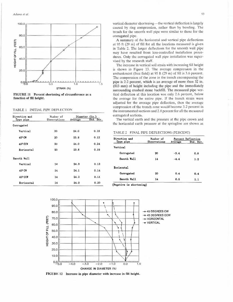
The increase in pipe wall circumferential strain (percent shortening of circumference) with increasing fill height is shown in Figure 11. Only one gauge is represented. The other three malfunctioned because of various problems during the early stages of construction. The 1.4 percent shortening at 95 ft (29 m) of fill, representing the average pipe wall compressive strain, is nearly the same as the average springline wall strain shown in Figure 10. However, the trend with fill heights for circumferential strain is more linear than that for the springline strains.
Initial deflection readings were taken when the height of cover over the pipe was 2.5 ft (0.8 m). The results, given in Table 1, show that the pipe was circular after. structural backfill placement and compaction.
The average pipe diameter changes with fill height are shown in Figure 12 for the instrumented pipe sections. The largest change was in the vertical diameter, which decreased by an average of 3.8 percent at 95 ft (29 m) of fill. The smallest change was in the horizontal diameter, \Vhich increased by an average of 0.4 percent at 95 ft (29 m) of fill. These results indicate that the pipe's circumference is shortening to produce
--e- CENTROID -A-CREST
+TROUGH
1.0 1.5
FIGURE 9 Increase in pipe wall strain with fill height.
COMPRESSION -l 1--1 BENDING
D AVERAGE STRAIN
CD
0 0.4 0.8 1.2 1.6 2·0 CREST
STRAIN(%)
FIGURE 10 Bending and compressive strains in the pipe wall with fill at 95 ft.
Adams el al.
STRAIN(%)
FIGURE 11 Percent shortening of circumference as a function of fill height.
TABLE 1 INITIAL PIPE DEFLECTION
Direction &nd Tree pipe
Corrugated
Vertical
45°cw
450 ccw
Horizontal
Smooth Wall
Vertical
45ocw
45° ccw
Horizontal
NUJDber of Observations
~ w !:!::.
20
20
20
20
14
14
14
14
100.0
90.0
80.0
70.0
Dia.meter ~in.) Average t.d. Dev.
24 .0
23.9
24.0
23.8
24.3
24.1
24 .2
24.0
I\.
~
'"'
0 . 16
0 . 12
0 .24
0.19
0.13
0 . 14
0 . 11
0.20
~
• \ \
60.0 --' --' u:: 50.0 "' u. 0 I- 40.0 :z: Cl iii 30.0 :z: I-
20.0
10.0 I-
h 0·~s.o -4.0 -3.0 -2.0
"'
\
93
vertical diameter shortening-the vertical deflection is largely caused by ring compression, rather than by bending. The trends for the smooth wall pipe were similar to those for the corrugated pipe.
A ummary of the horizontal and vertical pipe deflections at 95 ft (29 m) of fill for all the locations measured is given in Table 2. The larger deflections for the smooth wall pipe may have resulted from less-controlled installation procedures . Only the corrugated wall pipe installation was supervised by the research staff.
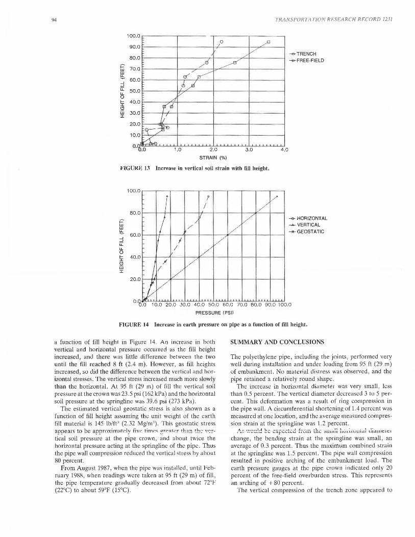
The increase in vertical soil strain with increasing fill height is shown in Figure 13. The average compression in the embankment (free field) at 95 ft (29 m) of fill is 3.6 percent . The compression of the zone in the trench encompassing the pipe i 2.2 percent which is <1 11 average of mor than 32 in . (813 mm) of height including the pipe and the immediately surrounding cru heel . tone ba kfill. T he measured pipe vertical deflection at this location was only 2.6 percent, below the average for the entire pipe. If the trench strain were adjusted for the average pipe deflection, then the average compression of the trench zone would become 3.2 percent in the instrumented sections and 2.8 percent for all the measured corrugated sections.
The vertical earth and the pressure at the pipe crown and the horizontal earth pressure at the springline are shown as
TABLE 2 FINAL PIPE DEFLECTIONS (PERCENT)
Direction &nd Number of '.!l:pe pipe Obser'tations
Vertical
Corrugated 20
Smooth Wall 14
Hori&ontal
Corrug&ted 20
Smooth Wall 14
(Negative is shortening)
h \
\ '\
\ { \ \
\ \ \
\ \ ·~
"""
..
f ; I/
..,a...45 DEGREES CW
-e-45 DEGREES CCW -e- HORIZONTAL _,,_VERTICAL
Percent Deflection Average Std. Dev.
-3.4 0.9
-4 .4 1.2
0.4. 0.4
0.5 1.1
-1 .0 0 .0 1.0
CHANGE IN DIAMETER (%)
FIGURE 12 Increase in pipe diameter with increase in fill height.
94
tii' w !::. --' --' u:: lL 0 1-:I: Cl iii :I:
1.0 2.0
STRAIN(%)
3.0
TRANS PORTA TI ON RESEA RCH RECORD 1231
--e-TRENCH
-<>-FREE-FIELD
4.0
FIGURE 13 Increase in vertical soil strain with fill height.
100.0
r r /'
80.0
r::-w w !::. 60.0 --' --' u:: lL 0 I- 40.0 :I: Cl iii :I:
20.0
I / /
I I /
/ . / - / /
/
I I / •'
I v·
·' , ,,./
/ / ;1 /
/ /
J-V,/
--e- HORIZONTAL
-.... VERTICAL
_,._ GEOSTATIC
0.0 0.0 10.0 20.0 30.0 40.0 50.0 60.0 70.0 80.0 90.0 100.0
PRESSURE tPSll
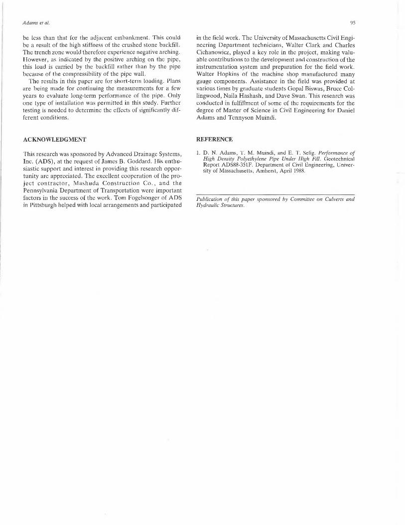
FIGURE 14 Increase in earth pressure on pipe as a function of fill height.
a function of fill height in Figure 14 . An increase in both vertical and horizontal pre · ure occurred as the fill height increa ed, and there was lillle difference between the two until the fill reached 8 t't (2.4 m) . H owever, as fill heights increased, so did the difference between the vertical and horizontal stresses. The vertical stress increased much more slowly th an the horizontal. At 95 ft (29 m) of fill the vertical oil pressure at the crown was 23.5 psi (162 kPa) and the horizontal soil pressure at the springline was 39.6 psi (273 kPa).
The estimated vertical geostatic stress is also shown as a function of fill height assuming the unit weight of the earth fill material is 145 lb/ft 3 (2.32 Mg/m3). This geostatic stress appears to be ap!'roximlltely five time< ~rPMP,.. th ?.!! th~ "~!
tical soil pressure at the pipe crown , and about twice the horizontal pressure acting at the springline of the pipe . Thus the pipe wall compression reduced the vertical stress by about 80 percent.
From August 1987, when the pipe was installed, until February 1988, when readings were taken at 95 ft (29 m) of fill , the pipe temperature gradually decreased from about 72°F (22°C) to about 59°F (15°C) .
SUMMARY AND CONCLUSIONS
The polyethylene pipe, including the joints, performed very well during installation and under loading from 95 ft (29 m) of embankment. No material distress was observed, and the pipe retained a relatively round shape .
The increase in horizontal diameter was very small, less than 0.5 percent . The vertical diameter decreased 3 to 5 percent. This deformation was a result of ring compression in the pipe wall. A circumferential shortening of 1.4 percent was measured at one location, and the average measured compression strain at the springline was 1.2 percent.
/'.. ~ ..... :~~!d 8~ ~~~~ctcd fIVili. ~lJ.c 3 iilal~ h01~Luula1 Jia.111clc1
change, the bending strain at the springline was small, an average of 0.3 percent. Thus the maximum combined strain at the springline was 1.5 percent. The pipe wall compression resulted in positive arching of the embankment load . The earth pressure gauges at the pipe crown indicated only 20 percent of the free-field overburden stress. This represents an arching of + 80 percent.
The vertical compression of the trench zone appeared to
Adams et al.
be less than that for the adjacent embankment. This could be a result of the high stiffness of the crushed stone backfill. The trench zone would therefore experience negative arching. However, as indicated by the positive arching on the pipe, this load is carried by the backfill rather than by the pipe because of the compressibility of the pipe wall.
The results in this paper are for short-term loading. Plans are being made for continuing the measurements for a few years to evaluate long-term performance of the pipe. Only one type of installation was permitted in this study. Further testing is needed to determine the effects of significantly different conditions.
ACKNOWLEDGMENT
This research was sponsored by Advanced Drainage Systems, Inc. (ADS), at the request of James B. Goddard. His enthusiastic support and interest in providing this research opportunity are appreciated. The excellent cooperation of the project contractor, Mashuda Construction Co., and the Pennsylvania Department of Transportation were important factors in the success of the work. Tom Fogelsonger of ADS in Pittsburgh helped with local arrangements and participated
95
in the field work. The University of Massachusetts Civil Engineering Department technicians, Walter Clark and Charles Cichanowicz, played a key role in the project, making valuable contributions to the development and construction of the instrumentation system and preparation for the field work. Walter Hopkins of the machine shop manufactured many gauge components. Assistance in the field was provided at various times by graduate students Gopal Biswas, Bruce Collingwood, Naila Hashash, and Dave Swan. This research was conducted in fulfillment of some of the requirements for the degree of Master of Science in Civil Engineering for Daniel Adams and Tennyson Muindi.
REFERENCE
1. D . N. Adams, T. M. Muindi , and E. T. Selig. Performance of High Density Polyethylene Pipe Under High Fill. Geotechnical Report ADS88-351F. Department of Civil Engineering, University of Massachusetts, Amherst, April 1988.
Publication of this paper sponsored by Committee on Culverts and Hydraulic Structures.