Embed Size (px)
Citation preview
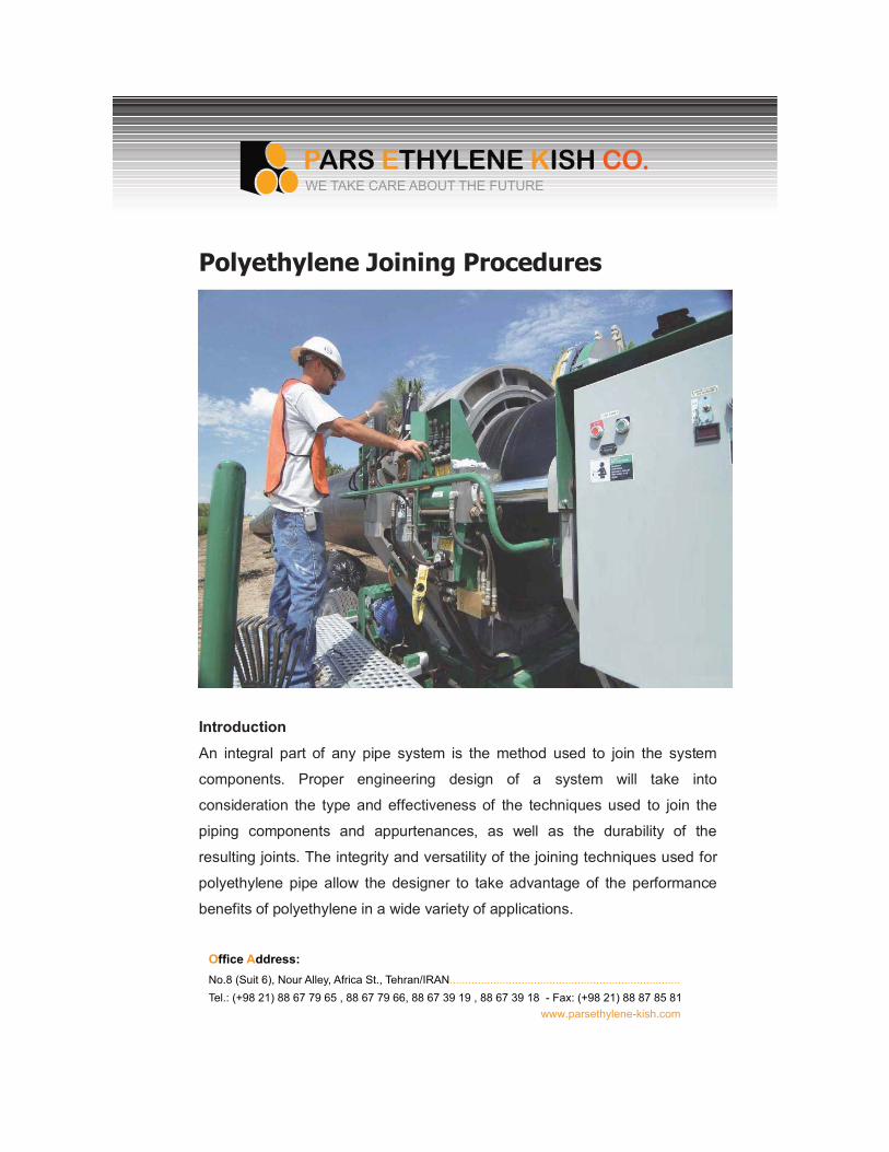
Polyethylene Joining Procedures
Introduction
An integral part of any pipe system is the method used to join the system
components. Proper engineering design of a system will take into
consideration the type and effectiveness of the techniques used to join the
piping components and appurtenances, as well as the durability of the
resulting joints. The integrity and versatility of the joining techniques used for
polyethylene pipe allow the designer to take advantage of the performance
benefits of polyethylene in a wide variety of applications.
O�����A����No.8 (Suit 6), Nour Alley, Africa St., Tehran/IRAN..........................................................................Tel.: (+98 21) 88 67 79 65 , 88 67 79 66, 88 67 39 19 , 88 67 39 18 - Fax: (+98 21) 88 87 85 81
www.parsethylene-kish.com
WE TAKE CARE ABOUT THE FUTURE
General Provisions
Polyethylene pipe or fittings are joined to each other by heat fusion or with
mechanical fittings. Polyethylene may be joined to other materials by means
of compression fittings, flanges, or other quilted types of manufactured
transition fittings. There are many types and styles of fittings available from
which the user may choose. Each offers its particular advantages and
limitations for each joining situation the user may encounter. Contact with the
various manufacturers is advisable for guidance in proper applications and
styles available for joining as described in this document. There will be joining
methods discussed in this document covering both large and small diameter
pipe. Large diameter pipe is considered to be sizes 3" IPS (3.500" OD) and
larger. Those persons who are involved in joining gas piping systems must
note certain qualification requirements of the U.S. Department of
Transportation Pipeline Safety Regulations.
Thermal Heat Fusion MethodsThere are three types of heat fusion joints currently used in the industry; Butt,
Saddle, and Socket Fusion. Additionally, there are two methods for producing
the socket and saddle heat fusion joints.
The principle of heat fusion is to heat two surfaces to a designated
temperature, and then fuse them together by application of a sufficient force.
This force causes the melted materials to flow and mix, thereby resulting in
fusion. When fused according to the pipe and/or fitting manufacturers
procedures, the joint area becomes as strong as, or strongAer than, the pipe
itself in both tensile and pressure properties. As soon as the joint cools to
near ambient temperature, it is ready for handling. The following sections of
this chapter provide a general procedural guideline for each of these heat
fusion methods.
O�����Address:No.8 (Suit 6), Nour Alley, Africa St., Tehran/IRAN..........................................................................Tel.: (+98 21) 88 67 79 65 , 88 67 79 66, 88 67 39 19 , 88 67 39 18 - Fax: (+98 21) 88 87 85 81
www.parsethylene-kish.com
WE TAKE CARE ABOUT THE FUTURE
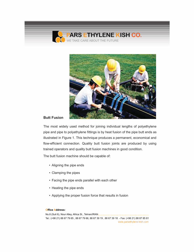
Butt Fusion
The most widely used method for joining individual lengths of polyethylene
pipe and pipe to polyethylene fittings is by heat fusion of the pipe butt ends as
illustrated in Figure 1. This technique produces a permanent, economical and
flow-efficient connection. Quality butt fusion joints are produced by using
trained operators and quality butt fusion machines in good condition.
The butt fusion machine should be capable of:
� Aligning the pipe ends
� Clamping the pipes
� Facing the pipe ends parallel with each other
� Heating the pipe ends
� Applying the proper fusion force that results in fusion
O�����A����No.8 (Suit 6), Nour Alley, Africa St., Tehran/IRAN..........................................................................Tel.: (+98 21) 88 67 79 65 , 88 67 79 66, 88 67 39 19 , 88 67 39 18 - Fax: (+98 21) 88 87 85 81
www.parsethylene-kish.com
WE TAKE CARE ABOUT THE FUTURE
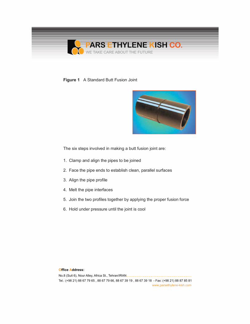
Figure 1 A Standard Butt Fusion Joint
The six steps involved in making a butt fusion joint are:
1. Clamp and align the pipes to be joined
2. Face the pipe ends to establish clean, parallel surfaces
3. Align the pipe profile
4. Melt the pipe interfaces
5. Join the two profiles together by applying the proper fusion force
6. Hold under pressure until the joint is cool
O�����Address:No.8 (Suit 6), Nour Alley, Africa St., Tehran/IRAN..........................................................................Tel.: (+98 21) 88 67 79 65 , 88 67 79 66, 88 67 39 19 , 88 67 39 18 - Fax: (+98 21) 88 87 85 81
www.parsethylene-kish.com
WE TAKE CARE ABOUT THE FUTURE
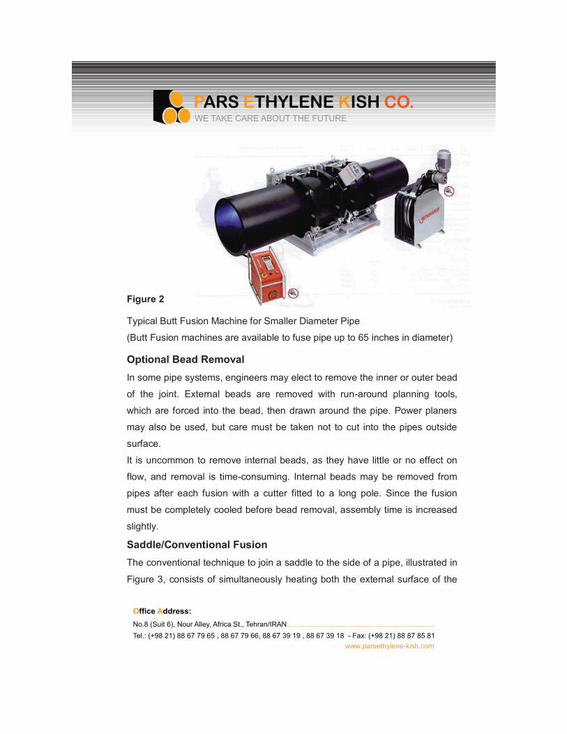
Figure 2
Typical Butt Fusion Machine for Smaller Diameter Pipe
(Butt Fusion machines are available to fuse pipe up to 65 inches in diameter)
Optional Bead RemovalIn some pipe systems, engineers may elect to remove the inner or outer bead
of the joint. External beads are removed with run-around planning tools,
which are forced into the bead, then drawn around the pipe. Power planers
may also be used, but care must be taken not to cut into the pipes outside
surface.
It is uncommon to remove internal beads, as they have little or no effect on
flow, and removal is time-consuming. Internal beads may be removed from
pipes after each fusion with a cutter fitted to a long pole. Since the fusion
must be completely cooled before bead removal, assembly time is increased
slightly.
Saddle/Conventional FusionThe conventional technique to join a saddle to the side of a pipe, illustrated in
Figure 3, consists of simultaneously heating both the external surface of the
O�����Address:No.8 (Suit 6), Nour Alley, Africa St., Tehran/IRAN..........................................................................Tel.: (+98 21) 88 67 79 65 , 88 67 79 66, 88 67 39 19 , 88 67 39 18 - Fax: (+98 21) 88 87 85 81
www.parsethylene-kish.com
WE TAKE CARE ABOUT THE FUTURE
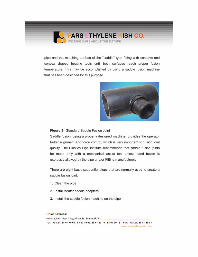
pipe and the matching surface of the "saddle" type fitting with concave and
convex shaped heating tools until both surfaces reach proper fusion
temperature. This may be accomplished by using a saddle fusion machine
that has been designed for this purpose
Figure 3 Standard Saddle Fusion Joint
Saddle fusion, using a properly designed machine, provides the operator
better alignment and force control, which is very important to fusion joint
quality. The Plastics Pipe Institute recommends that saddle fusion joints
be made only with a mechanical assist tool unless hand fusion is
expressly allowed by the pipe and/or Fitting manufacturer.
There are eight basic sequential steps that are normally used to create a
saddle fusion joint:
1. Clean the pipe
2. Install heater saddle adapters
3. Install the saddle fusion machine on the pipe
O�����Address:No.8 (Suit 6), Nour Alley, Africa St., Tehran/IRAN..........................................................................Tel.: (+98 21) 88 67 79 65 , 88 67 79 66, 88 67 39 19 , 88 67 39 18 - Fax: (+98 21) 88 87 85 81
www.parsethylene-kish.com
WE TAKE CARE ABOUT THE FUTURE
4. Prepare the surfaces of the pipe and fitting
5. Align the parts
6. Heat both the pipe and the saddle Fitting
7. Press and hold the parts together
8. Cool the joint and remove the fusion machine
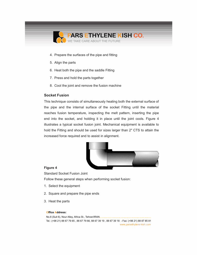
Socket FusionThis technique consists of simultaneously heating both the external surface of
the pipe and the internal surface of the socket Fitting until the material
reaches fusion temperature, inspecting the melt pattern, inserting the pipe
end into the socket, and holding it in place until the joint cools. Figure 4
illustrates a typical socket fusion joint. Mechanical equipment is available to
hold the Fitting and should be used for sizes larger than 2" CTS to attain the
increased force required and to assist in alignment.
Figure 4 Standard Socket Fusion Joint
Follow these general steps when performing socket fusion:
1. Select the equipment
2. Square and prepare the pipe ends
3. Heat the parts
O�����Address:No.8 (Suit 6), Nour Alley, Africa St., Tehran/IRAN..........................................................................Tel.: (+98 21) 88 67 79 65 , 88 67 79 66, 88 67 39 19 , 88 67 39 18 - Fax: (+98 21) 88 87 85 81
www.parsethylene-kish.com
WE TAKE CARE ABOUT THE FUTURE
4. Join the parts
5. Allow to cool
Equipment SelectionSelect the proper size tool faces and heat the tools to the fusion temperature
recommended for the material to be joined. For many years, socket fusion
tools were manufactured without benefit of any industry standardization. As a
result, variances of heater and socket depths and diameters, as well as depth
gauges, do exist. More recently, ASTM F1056(7) was written, establishing
standard dimensions for these tools. Therefore, mixing various manufacturers
heating tools or depth gauges is not recommended unless the tools are
marked "F1056," indicating compliance with the ASTM specification and,
thereby, consistency of tooling sizes.
Square and Prepare PipeCut the end of the pipe square. Chamfer the pipe end for sizes 1¼"-inch
diameter and larger. (Chamfering of smaller pipe sizes is acceptable and
sometimes specified in the instructions.) Remove any scraps, burrs,
shavings, oil, or dirt from the surfaces to be joined. Clamp the cold ring on the
pipe at the proper position, using the integral depth gauge pins or a separate
(thimble type) depth gauge. The cold ring will assist in re- rounding the pipe
and provide a stopping point for proper insertion of the pipe into the heating
tool and coupling during the fusion process.
HeatingCheck the heater temperature. Periodically verify the proper surface
temperature using a pyrometer or other surface temperature measuring
device. If temperature indicating markers are used, do not use them on a
O�����Address:No.8 (Suit 6), Nour Alley, Africa St., Tehran/IRAN..........................................................................Tel.: (+98 21) 88 67 79 65 , 88 67 79 66, 88 67 39 19 , 88 67 39 18 - Fax: (+98 21) 88 87 85 81
www.parsethylene-kish.com
WE TAKE CARE ABOUT THE FUTURE
surface that will come in contact with the pipe or fitting. Bring the hot clean
tool faces Into contact with the outside surface of the end of the pipe and with
the inside surface of the socket fitting, in accordance with pipe and Fitting
manufacturer's instructions. Procedures will vary with different materials.
Follow the instructions carefully.
JoiningSimultaneously remove the pipe and fitting from the tool using a quick Snap
action. Inspect the melt pattern for uniformity and immediately insert the pipe
squarely and fully into the socket of the fitting until the Fitting contacts the
cold ring. Do not twist the pipe or Fitting during or after the insertion, as is a
practice with some joining methods for other pipe materials.
CoolingHold or block the pipe in place so that the pipe cannot come out of the joint
while the mating surfaces are cooling. These cooling times are listed in the
pipe or Fitting manufacturer's instructions.
Electro fusionThis technique of heat fusion joining is somewhat different from the
conventional fusion joining thus far described. The main difference between
conventional heat fusion and electro fusion is the method by which the heat is
applied. In conventional heat fusion joining, a heating tool is used to heat the
pipe and Fitting surfaces. The electro fusion joint is heated internally, either
by a conductor at the interface of the joint or, as in one design, by a
conductive polymer. Heat is created as an electric current is applied to the
conductive material in the Fitting.
O�����Address:No.8 (Suit 6), Nour Alley, Africa St., Tehran/IRAN..........................................................................Tel.: (+98 21) 88 67 79 65 , 88 67 79 66, 88 67 39 19 , 88 67 39 18 - Fax: (+98 21) 88 87 85 81
www.parsethylene-kish.com
WE TAKE CARE ABOUT THE FUTURE
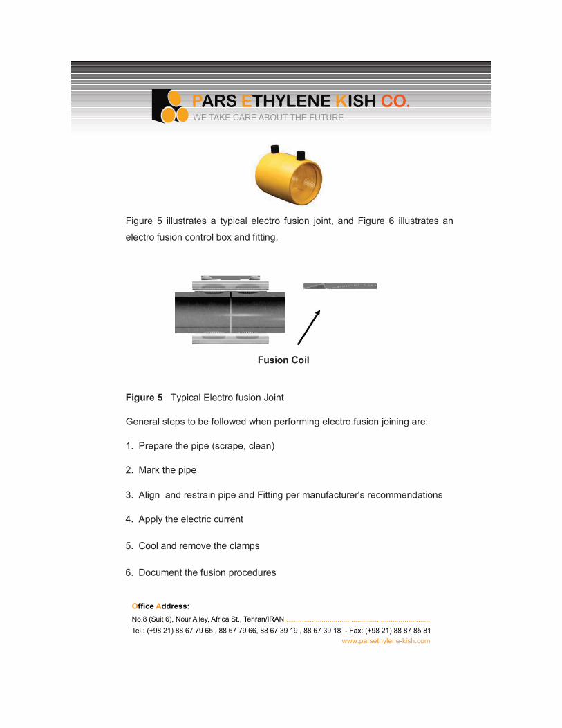
Figure 5 illustrates a typical electro fusion joint, and Figure 6 illustrates an
electro fusion control box and fitting.
Fusion Coil
Figure 5 Typical Electro fusion Joint
General steps to be followed when performing electro fusion joining are:
1. Prepare the pipe (scrape, clean)
2. Mark the pipe
3. Align and restrain pipe and Fitting per manufacturer's recommendations
4. Apply the electric current
5. Cool and remove the clamps
6. Document the fusion procedures
O�����Address:No.8 (Suit 6), Nour Alley, Africa St., Tehran/IRAN..........................................................................Tel.: (+98 21) 88 67 79 65 , 88 67 79 66, 88 67 39 19 , 88 67 39 18 - Fax: (+98 21) 88 87 85 81
www.parsethylene-kish.com
WE TAKE CARE ABOUT THE FUTURE
Prepare the Pipe (Clean and Scrape)
Assure the pipe ends are cut square when joining couplings. The fusion area
must be clean from dirt's or contaminants. This may require the use of water
or 90% isopropyl alcohol (NO ADDITIVES OR NOT DENATURED). Scraping:
The pipe surface in the fusion area must be removed to expose clean virgin
material. This may be achieved by a various manufactured tools.
Mark the Pipe
Mark the pipe for stab depth of couplings and proper fusion location of
saddles. (Caution should be taken to assure that a non-petroleum marker is
used.)
Align and Restrain Pipe or Fitting Per the Manufacturer’s Recommendations
Align and restrain Fitting to pipe per manufacturer's recommendations. Place
the pipe(s) and Fitting in the clamping Fixture to prevent movement of the
pipe(s) or Fitting. Give special attention to proper positioning of the Fitting on
the prepared pipe surfaces. Rerounding of pipe may be required with larger
diameters.
O�����Address:No.8 (Suit 6), Nour Alley, Africa St., Tehran/IRAN..........................................................................Tel.: (+98 21) 88 67 79 65 , 88 67 79 66, 88 67 39 19 , 88 67 39 18 - Fax: (+98 21) 88 87 85 81
www.parsethylene-kish.com
WE TAKE CARE ABOUT THE FUTURE
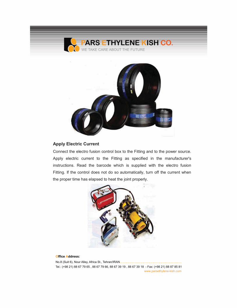
Apply Electric CurrentConnect the electro fusion control box to the Fitting and to the power source.
Apply electric current to the Fitting as specified in the manufacturer's
instructions. Read the barcode which is supplied with the electro fusion
Fitting. If the control does not do so automatically, turn off the current when
the proper time has elapsed to heat the joint properly.
O�����Address:No.8 (Suit 6), Nour Alley, Africa St., Tehran/IRAN..........................................................................Tel.: (+98 21) 88 67 79 65 , 88 67 79 66, 88 67 39 19 , 88 67 39 18 - Fax: (+98 21) 88 87 85 81
www.parsethylene-kish.com
WE TAKE CARE ABOUT THE FUTURE
Typical Electro fusion Control Box and Leads with Clamps and Fittings
Cool Joint and Remove ClampsAllow the joint to cool for the recommended time. If using clamps, premature
removal from the clamps and any strain on a joint that has not fully cooled
can be detrimental to joint performance.
Consult the fitting manufacturer for detailed parameters and procedures.
Documenting FusionThe Electro fusion control box that applies current to the Fitting also controls
and monitors the critical parameters of fusion, (time, temperature, &
pressure). The control box is a micro- processor capable of storing the
specific fusion data for each joint. This information can be downloaded to a
computer for documentation and inspection of the day's work.
Heat Fusion Joining of Unlike Polyethylene Pipe and FittingsResearch has indicated that polyethylene pipe and fittings made from unlike
resins can be heat-fused together to make satisfactory joints. Some gas
companies have been heat-fusion joining unlike polyethylene's for many
years with success.
Mechanical Connections
As in the heat fusion methods, many types of mechanical connection styles
and methods are available. This section is a general description of these
types of Fittings.
Fitting selection is important to the performance of a piping system. Product
performance and application information should be available from the Fitting
O�����Address:No.8 (Suit 6), Nour Alley, Africa St., Tehran/IRAN..........................................................................Tel.: (+98 21) 88 67 79 65 , 88 67 79 66, 88 67 39 19 , 88 67 39 18 - Fax: (+98 21) 88 87 85 81
www.parsethylene-kish.com
WE TAKE CARE ABOUT THE FUTURE
Figure6
manufacturer to assist in the selection process as well as instructions for use
and performance limits, if any. Additional information for these types of
products is also contained in a variety of specifications such as ASTM F1924,
F1973, AWWA C219, and UNI-B-13.
Polyethylene pipe, conduit and Fittings are available in outside diameter
controlled Iron Pipe Sizes (IPS), Ductile Iron Pipe Sizes (DIPS), Copper
Tubing Sizes (CTS) and Metric Sizes. There are also some inside diameter
controlled pipe sizes (SIDR-PR). Before selecting mechanical Fittings,
establish which of the available piping system sizes and types are being
installed to ensure proper Fit and function. The pipe manufacturer can
provide dimensional information, and the Fitting manufacturer can advise on
the correct Fitting selection for the application.
Mechanical Compression Couplings for Small Diameter Pipes
This style of fitting comes in many forms and materials. The components, as
depicted in Figure 7, are generally a body; a threaded compression nut; an
elastomeric seal ring or O-ring; a stiffener; and, with some, a grip ring. The
seal and grip rings, when compressed, grip the outside of the pipe, affecting a
pressure-tight seal and, in most designs, providing pullout resistance which
exceeds the yield strength of the polyethylene pipe. It is important that the
inside of the pipe wall be supported by the stiffener under the seal ring and
under the gripping ring (if incorporated in the design), to avoid deflection of
the pipe. A lack of this support could result in a loss of the seal or the gripping
of the pipe for pullout resistance. This Fitting style is normally used in service
lines for gas or water pipe 2" IPS and smaller. It is also important to consider
that three categories of this type of joining device are available. One type is
recommended to provide a seal only, a second provides a seal and some
restraint from pullout and a third provides a seal plus full pipe restraint against
pullout.O�����Address:No.8 (Suit 6), Nour Alley, Africa St., Tehran/IRAN..........................................................................Tel.: (+98 21) 88 67 79 65 , 88 67 79 66, 88 67 39 19 , 88 67 39 18 - Fax: (+98 21) 88 87 85 81
www.parsethylene-kish.com
WE TAKE CARE ABOUT THE FUTURE
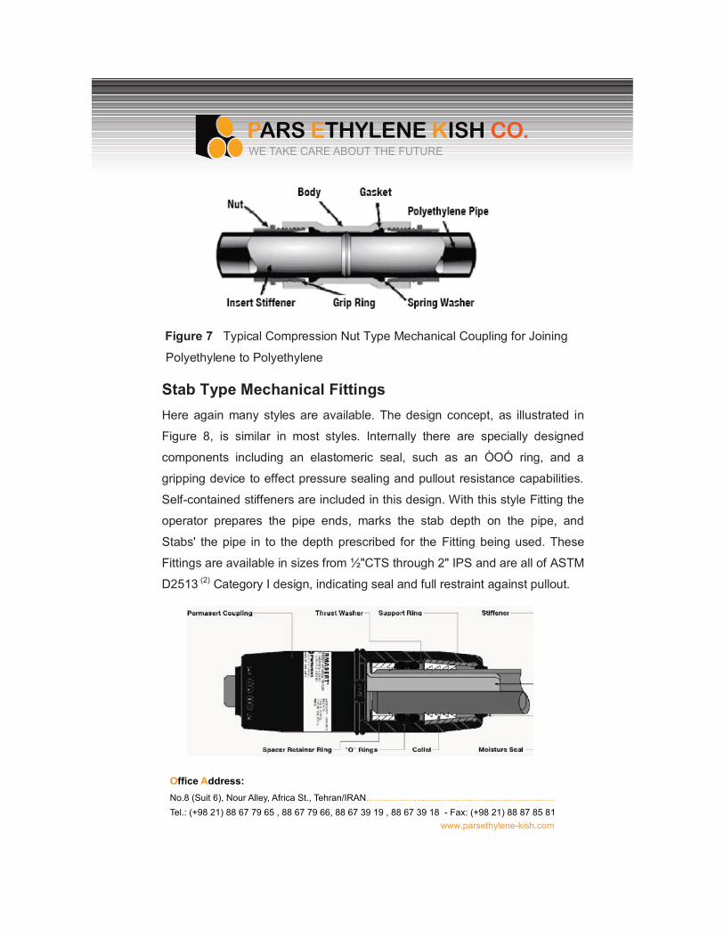
Figure 7 Typical Compression Nut Type Mechanical Coupling for Joining
Polyethylene to Polyethylene
Stab Type Mechanical FittingsHere again many styles are available. The design concept, as illustrated in
Figure 8, is similar in most styles. Internally there are specially designed
components including an elastomeric seal, such as an ÒOÓ ring, and a
gripping device to effect pressure sealing and pullout resistance capabilities.
Self-contained stiffeners are included in this design. With this style Fitting the
operator prepares the pipe ends, marks the stab depth on the pipe, and
Stabs' the pipe in to the depth prescribed for the Fitting being used. These
Fittings are available in sizes from ½"CTS through 2" IPS and are all of ASTM
D2513 (2) Category I design, indicating seal and full restraint against pullout.
O�����Address:No.8 (Suit 6), Nour Alley, Africa St., Tehran/IRAN..........................................................................Tel.: (+98 21) 88 67 79 65 , 88 67 79 66, 88 67 39 19 , 88 67 39 18 - Fax: (+98 21) 88 87 85 81
www.parsethylene-kish.com
WE TAKE CARE ABOUT THE FUTURE
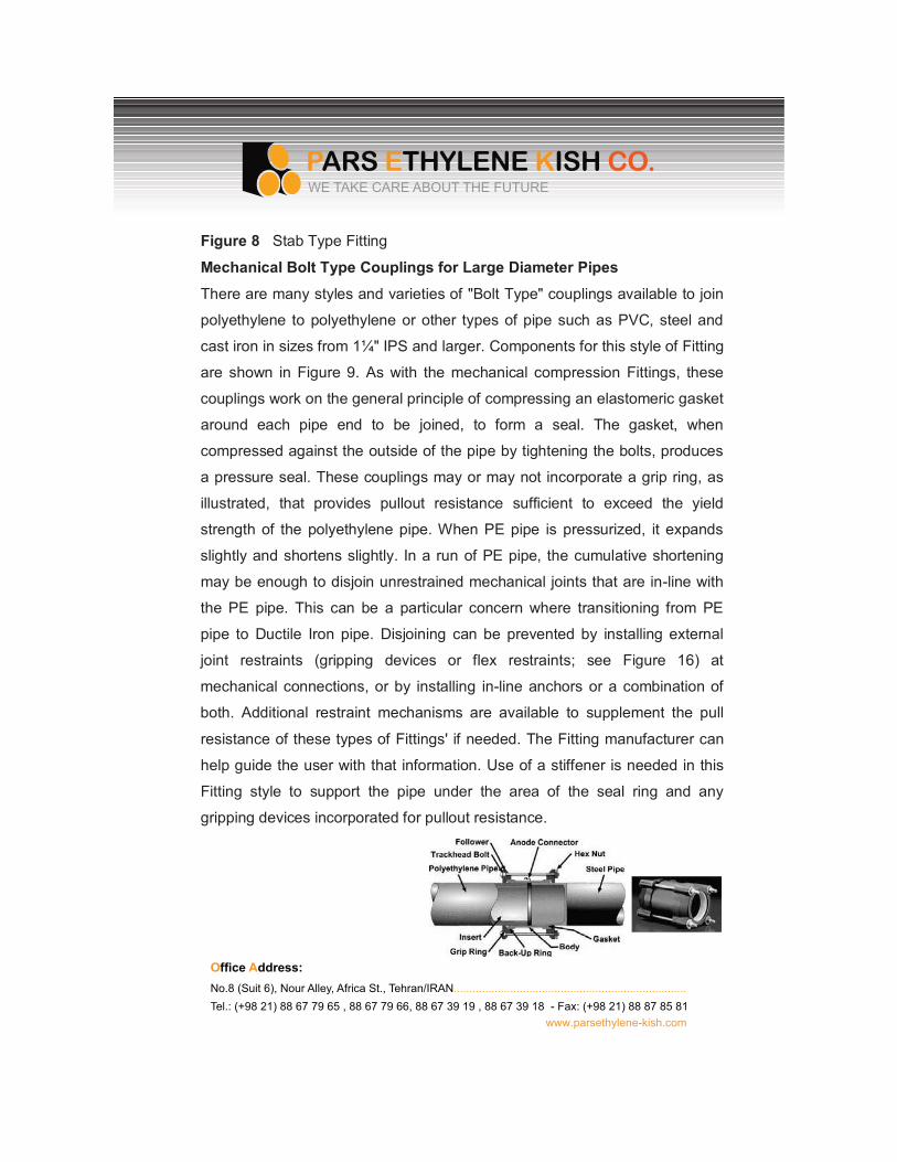
Figure 8 Stab Type Fitting
Mechanical Bolt Type Couplings for Large Diameter Pipes
There are many styles and varieties of "Bolt Type" couplings available to join
polyethylene to polyethylene or other types of pipe such as PVC, steel and
cast iron in sizes from 1¼" IPS and larger. Components for this style of Fitting
are shown in Figure 9. As with the mechanical compression Fittings, these
couplings work on the general principle of compressing an elastomeric gasket
around each pipe end to be joined, to form a seal. The gasket, when
compressed against the outside of the pipe by tightening the bolts, produces
a pressure seal. These couplings may or may not incorporate a grip ring, as
illustrated, that provides pullout resistance sufficient to exceed the yield
strength of the polyethylene pipe. When PE pipe is pressurized, it expands
slightly and shortens slightly. In a run of PE pipe, the cumulative shortening
may be enough to disjoin unrestrained mechanical joints that are in-line with
the PE pipe. This can be a particular concern where transitioning from PE
pipe to Ductile Iron pipe. Disjoining can be prevented by installing external
joint restraints (gripping devices or flex restraints; see Figure 16) at
mechanical connections, or by installing in-line anchors or a combination of
both. Additional restraint mechanisms are available to supplement the pull
resistance of these types of Fittings' if needed. The Fitting manufacturer can
help guide the user with that information. Use of a stiffener is needed in this
Fitting style to support the pipe under the area of the seal ring and any
gripping devices incorporated for pullout resistance.
O�����Address:No.8 (Suit 6), Nour Alley, Africa St., Tehran/IRAN..........................................................................Tel.: (+98 21) 88 67 79 65 , 88 67 79 66, 88 67 39 19 , 88 67 39 18 - Fax: (+98 21) 88 87 85 81
www.parsethylene-kish.com
WE TAKE CARE ABOUT THE FUTURE
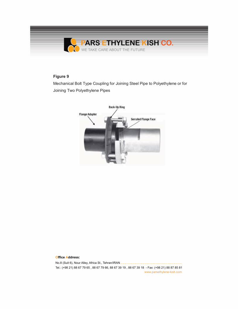
Figure 9
Mechanical Bolt Type Coupling for Joining Steel Pipe to Polyethylene or for
Joining Two Polyethylene Pipes
O�����Address:No.8 (Suit 6), Nour Alley, Africa St., Tehran/IRAN..........................................................................Tel.: (+98 21) 88 67 79 65 , 88 67 79 66, 88 67 39 19 , 88 67 39 18 - Fax: (+98 21) 88 87 85 81
www.parsethylene-kish.com
WE TAKE CARE ABOUT THE FUTURE
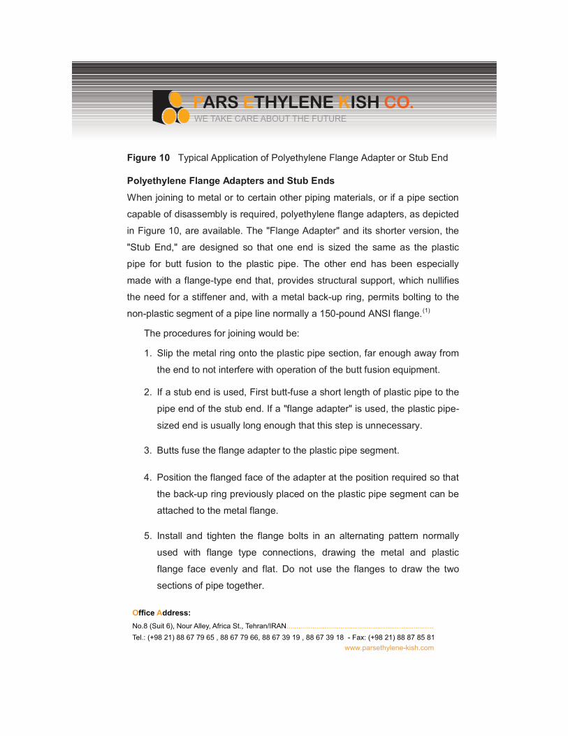
Figure 10 Typical Application of Polyethylene Flange Adapter or Stub End
Polyethylene Flange Adapters and Stub Ends
When joining to metal or to certain other piping materials, or if a pipe section
capable of disassembly is required, polyethylene flange adapters, as depicted
in Figure 10, are available. The "Flange Adapter" and its shorter version, the
"Stub End," are designed so that one end is sized the same as the plastic
pipe for butt fusion to the plastic pipe. The other end has been especially
made with a flange-type end that, provides structural support, which nullifies
the need for a stiffener and, with a metal back-up ring, permits bolting to the
non-plastic segment of a pipe line normally a 150-pound ANSI flange.(1)
The procedures for joining would be:
1. Slip the metal ring onto the plastic pipe section, far enough away from
the end to not interfere with operation of the butt fusion equipment.
2. If a stub end is used, First butt-fuse a short length of plastic pipe to the
pipe end of the stub end. If a "flange adapter" is used, the plastic pipe-
sized end is usually long enough that this step is unnecessary.
3. Butts fuse the flange adapter to the plastic pipe segment.
4. Position the flanged face of the adapter at the position required so that
the back-up ring previously placed on the plastic pipe segment can be
attached to the metal flange.
5. Install and tighten the flange bolts in an alternating pattern normally
used with flange type connections, drawing the metal and plastic
flange face evenly and flat. Do not use the flanges to draw the two
sections of pipe together.
O�����Address:No.8 (Suit 6), Nour Alley, Africa St., Tehran/IRAN..........................................................................Tel.: (+98 21) 88 67 79 65 , 88 67 79 66, 88 67 39 19 , 88 67 39 18 - Fax: (+98 21) 88 87 85 81
www.parsethylene-kish.com
WE TAKE CARE ABOUT THE FUTURE
O�����A����No.8 (Suit 6), Nour Alley, Africa St., Tehran/IRAN..........................................................................Tel.: (+98 21) 88 67 79 65 , 88 67 79 66, 88 67 39 19 , 88 67 39 18 - Fax: (+98 21) 88 87 85 81
www.parsethylene-kish.com
WE TAKE CARE ABOUT THE FUTURE
At lower pressure, typically 80 psi or less, a gasket is usually not required. At
greater pressure, the serrated surface of the flange adapter helps hold the
gasket in place. The flange faces serration's should be individual closed
concentric serration's as opposed to a continuous spiral groove which could
act as a leak path. Standard Back-Up Rings are AWWA C207 Class D for 160
psi and lower pressure ratings, or Class 150 for higher pressure. Back-up ring
materials are steel, primer coated steel, epoxy coated steel, or stainless steel.
Ductile iron and Fiberglass are also available. In below ground service,
coatings and cathodic protection may be appropriate to protect metal back-up
rings from corrosion. One edge of the back-up ring bore must be radiuses or
chamfered. This edge Fits' against the back of the sealing surface flange.
An all-polyethylene flange without a back-up ring is not recommended
because polyethylene flanges require uniform pressure over the entire sealing
surface. Absent a back-up ring, a polyethylene flange will leak between the
bolts.
Flange adapters differ from stub-ends by their overall length. A flange adapter
is longer allowing it to be clamped in a fusion machine like a pipe end. The
back-up ring is Fitted to the flange adapter before fusion, so external fusion
bead removal is not required.
A stub end is short and requires a special stub-end holder for butt fusion.
Once butt fused to the pipe, the external bead must be removed so the back-
up ring can be Fitted behind the sealing surface flange. In the Field, flange
adapters are usually preferred over stub-ends.
Flang��Gak�tA flange gasket may not be required between polyethylene flanges. At lower
pressures (typically 80 psi or less) the serrated flange sealing surface may be
adequate. Gaskets may be needed for higher pressures and for connections
between polyethylene and non-polyethylene flanges. If used, gasket materials
should be chemically and thermally compatible with the internal fluid and the
external environment, and should be of appropriate hardness, thickness and
style. Elevated temperature applications may require higher temperature
capability. Gasket thickness should be about 1/8"-3/16" (3-5mm) and about
55-75 udometer Shore D hardness. Too soft or too thick gaskets may bow out
under pressure. Overly hard gaskets may not seal. Common gasket styles are
full-face or drop-in. Full-face style gaskets are usually applied to larger sizes,
because flange bolts hold a flexible gasket in place while Fitting the
components together. Drop-in style gaskets are usually applied to smaller
pipe sizes.
Flange BoltingMating flanges are usually joined together with hex bolts and hex nuts, or
threaded studs and hex nuts. Bolting materials should have tensile strength
equivalent to at least SAE Grade 3 for pressure pipe service, and to at least
SAE Grade 2 for non-pressure service. Corrosion resistant materials should
be considered for underground, underwater, or other corrosive environments.
Flange bolts are sized 1/8" smaller than the blot hole diameter. Flat washers
should be used between the nut and the back-up ring.
Flange bolts must span the entire width of the flange joint, and provide
sufficient thread length to fully engage the nut.
Flange Assembly
Mating flanges must be aligned together before tightening. Tightening
misaligned flanges can cause flange failure. Surface or above grade flanges
must be properly supported to avoid bending stresses. Below grade flange
connections to heavy appurtenances such as valves or hydrants, or to metal
pipes, require a support foundation of compacted, stable granular soil
(crushed stone), or compacted cement stabilized granular backfill, or
reinforced concrete. Flange connections adjacent to pipes passing through
structural walls must be structurally supported to avoid shear loads.
O�����Address:No.8 (Suit 6), Nour Alley, Africa St., Tehran/IRAN..........................................................................Tel.: (+98 21) 88 67 79 65 , 88 67 79 66, 88 67 39 19 , 88 67 39 18 - Fax: (+98 21) 88 87 85 81
www.parsethylene-kish.com
WE TAKE CARE ABOUT THE FUTURE
Prior to Fit-up, lubricate flange bolt threads, washers, and nuts with a non-
fluid lubricant. Gasket and fl anger sealing surfaces must be clean and free of
significant cuts or gouges. Fit the flange components together loosely. Hand-
tighten bolts and re-check alignment. Adjust alignment if necessary. Flange
bolts should be tightened to the same torque value by turning the nut. Tighten
each bolt according to the patterns and torques recommended by the flange
manufacturer. Polyethylene and the gasket (if used) will undergo some
compression set. Therefore, retightening is recommended about an hour or
so after torquing to the final torque value the First time. In pattern sequence,
retighten each bolt to the final torque value. For high pressure or
environmentally sensitive or critical pipelines, a third tightening, about 4 hours
after the second, is recommended.
Special CasesWhen flanging to brittle materials such as cast iron, accurate alignment, and
careful tightening are necessary. Tightening torque increments should not
exceed 10 ft.-lbs. Polyethylene flange adapters and stub ends are not full-
face, so tightening places a bending stress across the flange face. Over-
tightening, misalignment, or uneven tightening can break brittle material
flanges.
When joining a polyethylene flange adapter or stub end to a flanged butterfly
valve, the inside diameter of the pipe flange should be checked for valve disk
rotation clearance. The open valve disk may extend into the pipe flange.
Valve operation may be restricted if the pipe flange interferes with the disk. If
disk rotation clearance is a problem, a tubular spacer may be installed
between the mating flanges, or the pipe fl ange bore may be chamfered
slightly. At the sealing surface, chamfering must not increase the flange inside
diameter by more than 10%, and not extend into the flange more than 20% of
the flange thickness. Flange bolt length must be increased by the length of
O�����Address:No.8 (Suit 6), Nour Alley, Africa St., Tehran/IRAN..........................................................................Tel.: (+98 21) 88 67 79 65 , 88 67 79 66, 88 67 39 19 , 88 67 39 18 - Fax: (+98 21) 88 87 85 81
www.parsethylene-kish.com
WE TAKE CARE ABOUT THE FUTURE
the spacer.
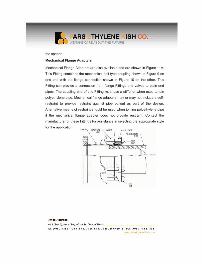
Mechanical Flange Adapters
Mechanical Flange Adapters are also available and are shown in Figure 11A.
This Fitting combines the mechanical bolt type coupling shown in Figure 9 on
one end with the flange connection shown in Figure 10 on the other. This
Fitting can provide a connection from flange Fittings and valves to plain end
pipes. The coupling end of this Fitting must use a stiffener when used to join
polyethylene pipe. Mechanical flange adapters may or may not include a self-
restraint to provide restraint against pipe pullout as part of the design.
Alternative means of restraint should be used when joining polyethylene pipe
if the mechanical flange adapter does not provide restraint. Contact the
manufacturer of these Fittings for assistance in selecting the appropriate style
for the application.
O�����Address:No.8 (Suit 6), Nour Alley, Africa St., Tehran/IRAN..........................................................................Tel.: (+98 21) 88 67 79 65 , 88 67 79 66, 88 67 39 19 , 88 67 39 18 - Fax: (+98 21) 88 87 85 81
www.parsethylene-kish.com
WE TAKE CARE ABOUT THE FUTURE
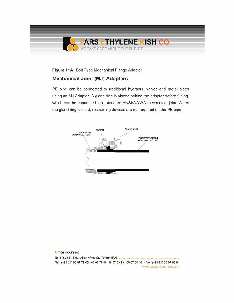
PE pipe can be connected to traditional hydrants, valves and metal pipes
using an MJ Adapter. A gland ring is placed behind the adapter before fusing,
which can be connected to a standard ANSI/AWWA mechanical joint. When
the gland ring is used, restraining devices are not required on the PE pipe.
O�����A����No.8 (Suit 6), Nour Alley, Africa St., Tehran/IRAN..........................................................................Tel.: (+98 21) 88 67 79 65 , 88 67 79 66, 88 67 39 19 , 88 67 39 18 - Fax: (+98 21) 88 87 85 81
www.parsethylene-kish.com
WE TAKE CARE ABOUT THE FUTURE
Figur��11A���Bolt Type Mechanical Flange Adapter
M��hani�al�Joint�(MJ)�Adapt�r
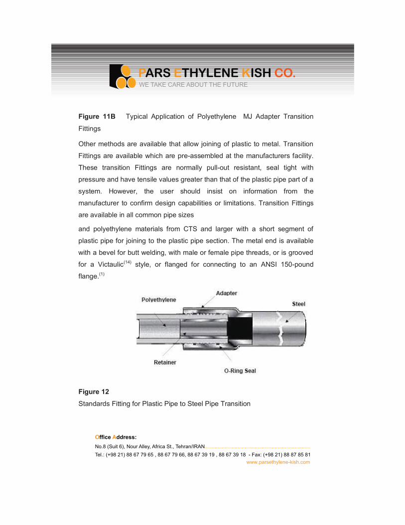
Figure 11B Typical Application of Polyethylene MJ Adapter Transition
Fittings
Other methods are available that allow joining of plastic to metal. Transition
Fittings are available which are pre-assembled at the manufacturers facility.
These transition Fittings are normally pull-out resistant, seal tight with
pressure and have tensile values greater than that of the plastic pipe part of a
system. However, the user should insist on information from the
manufacturer to confirm design capabilities or limitations. Transition Fittings
are available in all common pipe sizes
and polyethylene materials from CTS and larger with a short segment of
plastic pipe for joining to the plastic pipe section. The metal end is available
with a bevel for butt welding, with male or female pipe threads, or is grooved
for a Victaulic(14) style, or flanged for connecting to an ANSI 150-pound
flange.(1)
Figure 12
Standards Fitting for Plastic Pipe to Steel Pipe Transition
O�����Address:No.8 (Suit 6), Nour Alley, Africa St., Tehran/IRAN..........................................................................Tel.: (+98 21) 88 67 79 65 , 88 67 79 66, 88 67 39 19 , 88 67 39 18 - Fax: (+98 21) 88 87 85 81
www.parsethylene-kish.com
WE TAKE CARE ABOUT THE FUTURE
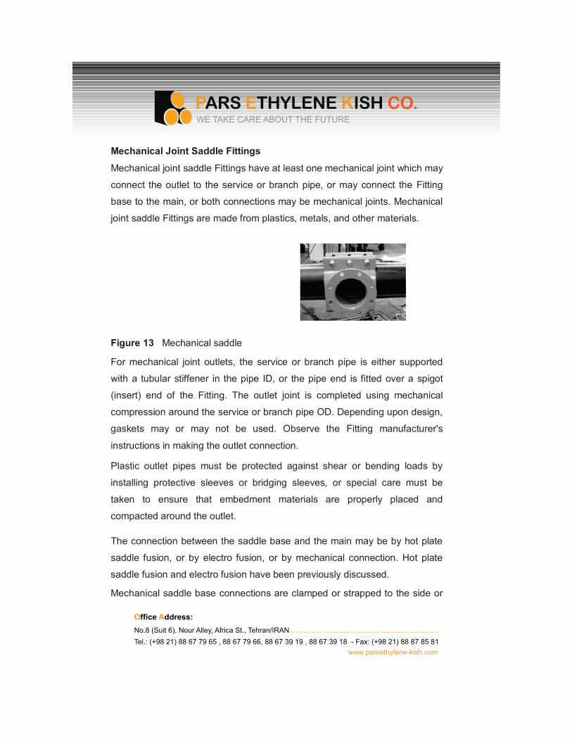
Mechanical Joint Saddle Fittings
Mechanical joint saddle Fittings have at least one mechanical joint which may
connect the outlet to the service or branch pipe, or may connect the Fitting
base to the main, or both connections may be mechanical joints. Mechanical
joint saddle Fittings are made from plastics, metals, and other materials.
Figure 13 Mechanical saddle
For mechanical joint outlets, the service or branch pipe is either supported
with a tubular stiffener in the pipe ID, or the pipe end is fitted over a spigot
(insert) end of the Fitting. The outlet joint is completed using mechanical
compression around the service or branch pipe OD. Depending upon design,
gaskets may or may not be used. Observe the Fitting manufacturer's
instructions in making the outlet connection.
Plastic outlet pipes must be protected against shear or bending loads by
installing protective sleeves or bridging sleeves, or special care must be
taken to ensure that embedment materials are properly placed and
compacted around the outlet.
The connection between the saddle base and the main may be by hot plate
saddle fusion, or by electro fusion, or by mechanical connection. Hot plate
saddle fusion and electro fusion have been previously discussed.
Mechanical saddle base connections are clamped or strapped to the side or
O�����Address:No.8 (Suit 6), Nour Alley, Africa St., Tehran/IRAN..........................................................................Tel.: (+98 21) 88 67 79 65 , 88 67 79 66, 88 67 39 19 , 88 67 39 18 - Fax: (+98 21) 88 87 85 81
www.parsethylene-kish.com
WE TAKE CARE ABOUT THE FUTURE
top of the main pipe. Typically, gaskets or o-rings are used to seal between
the saddle base and the main pipe OD surface to prevent leakage when the
main wall is pierced. Once secured to the main per the Fitting manufacturer's
instructions, the main may be pierced to allow flow into the service or branch
pipe.
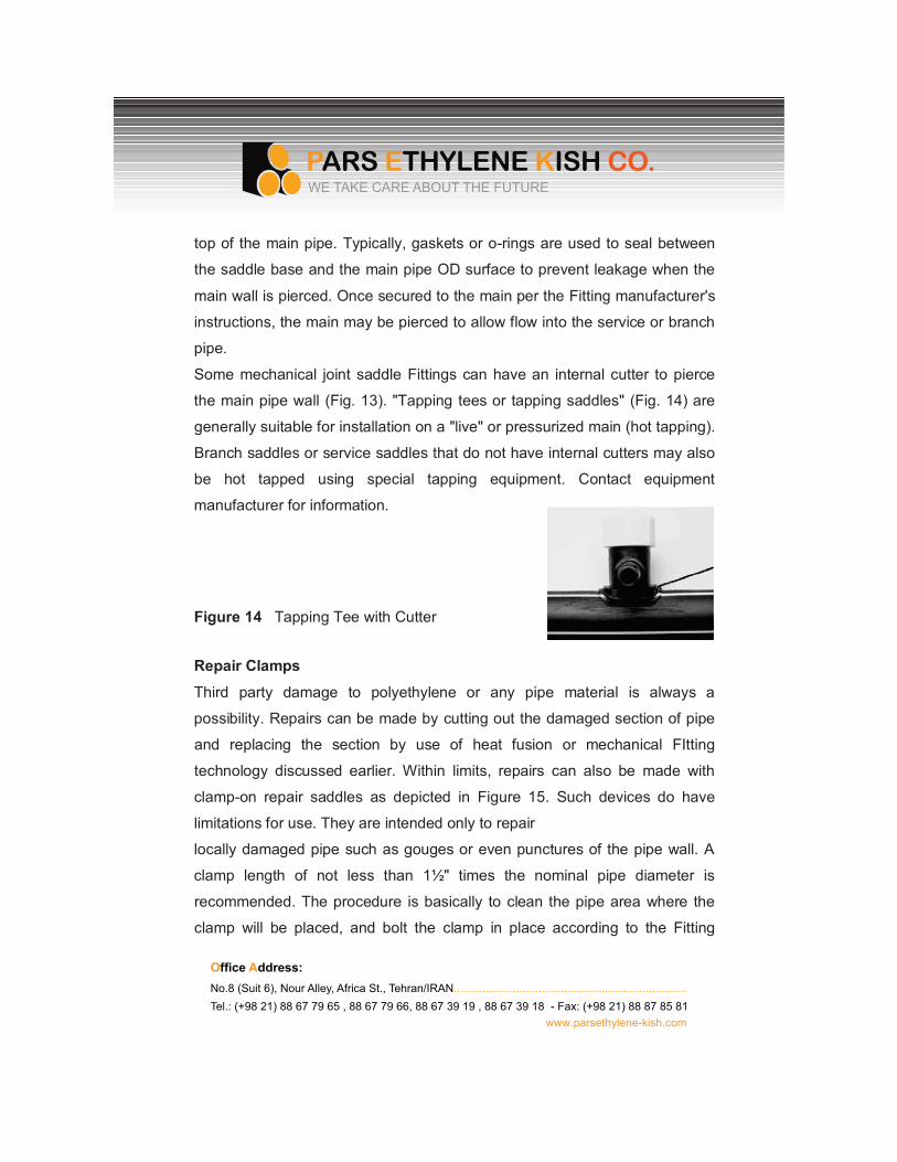
Some mechanical joint saddle Fittings can have an internal cutter to pierce
the main pipe wall (Fig. 13). "Tapping tees or tapping saddles" (Fig. 14) are
generally suitable for installation on a "live" or pressurized main (hot tapping).
Branch saddles or service saddles that do not have internal cutters may also
be hot tapped using special tapping equipment. Contact equipment
manufacturer for information.
Figure 14 Tapping Tee with Cutter
Repair Clamps
Third party damage to polyethylene or any pipe material is always a
possibility. Repairs can be made by cutting out the damaged section of pipe
and replacing the section by use of heat fusion or mechanical FItting
technology discussed earlier. Within limits, repairs can also be made with
clamp-on repair saddles as depicted in Figure 15. Such devices do have
limitations for use. They are intended only to repair
locally damaged pipe such as gouges or even punctures of the pipe wall. A
clamp length of not less than 1½" times the nominal pipe diameter is
recommended. The procedure is basically to clean the pipe area where the
clamp will be placed, and bolt the clamp in place according to the Fitting
O�����Address:No.8 (Suit 6), Nour Alley, Africa St., Tehran/IRAN..........................................................................Tel.: (+98 21) 88 67 79 65 , 88 67 79 66, 88 67 39 19 , 88 67 39 18 - Fax: (+98 21) 88 87 85 81
www.parsethylene-kish.com
WE TAKE CARE ABOUT THE FUTURE
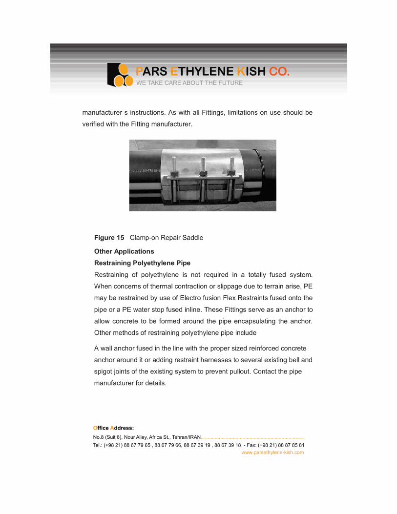
manufacturer s instructions. As with all Fittings, limitations on use should be
verified with the Fitting manufacturer.
Figure 15 Clamp-on Repair Saddle
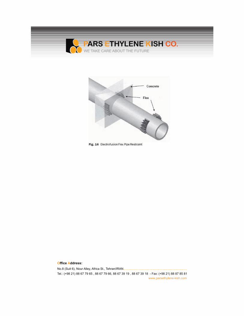
Other ApplicationsRestraining Polyethylene Pipe
Restraining of polyethylene is not required in a totally fused system.
When concerns of thermal contraction or slippage due to terrain arise, PE
may be restrained by use of Electro fusion Flex Restraints fused onto the
pipe or a PE water stop fused inline. These Fittings serve as an anchor to
allow concrete to be formed around the pipe encapsulating the anchor.
Other methods of restraining polyethylene pipe include
A wall anchor fused in the line with the proper sized reinforced concrete
anchor around it or adding restraint harnesses to several existing bell and
spigot joints of the existing system to prevent pullout. Contact the pipe
manufacturer for details.
O�����Address:No.8 (Suit 6), Nour Alley, Africa St., Tehran/IRAN..........................................................................Tel.: (+98 21) 88 67 79 65 , 88 67 79 66, 88 67 39 19 , 88 67 39 18 - Fax: (+98 21) 88 87 85 81
www.parsethylene-kish.com
WE TAKE CARE ABOUT THE FUTURE
O�����A����No.8 (Suit 6), Nour Alley, Africa St., Tehran/IRAN..........................................................................Tel.: (+98 21) 88 67 79 65 , 88 67 79 66, 88 67 39 19 , 88 67 39 18 - Fax: (+98 21) 88 87 85 81
www.parsethylene-kish.com
WE TAKE CARE ABOUT THE FUTURE
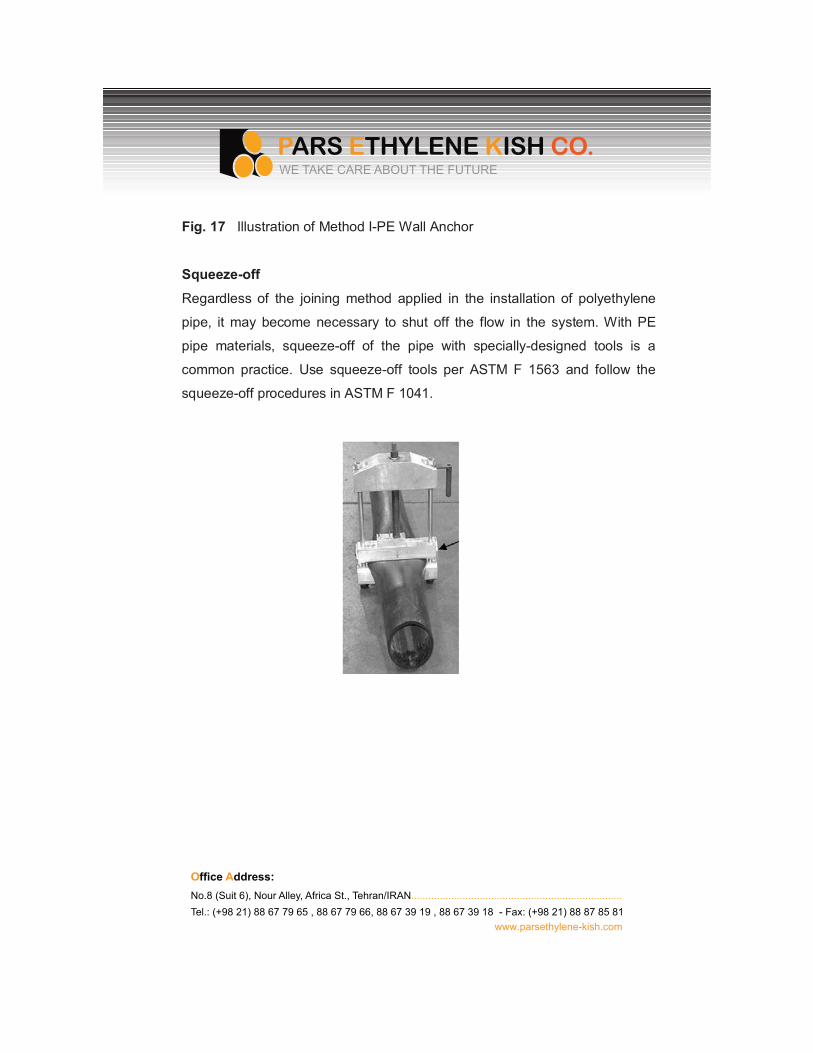
Fig. 17 Illustration of Method I-PE Wall Anchor
Squeeze-off
Regardless of the joining method applied in the installation of polyethylene
pipe, it may become necessary to shut off the flow in the system. With PE
pipe materials, squeeze-off of the pipe with specially-designed tools is a
common practice. Use squeeze-off tools per ASTM F 1563 and follow the
squeeze-off procedures in ASTM F 1041.
O�����Address:No.8 (Suit 6), Nour Alley, Africa St., Tehran/IRAN..........................................................................Tel.: (+98 21) 88 67 79 65 , 88 67 79 66, 88 67 39 19 , 88 67 39 18 - Fax: (+98 21) 88 87 85 81
www.parsethylene-kish.com
WE TAKE CARE ABOUT THE FUTURE
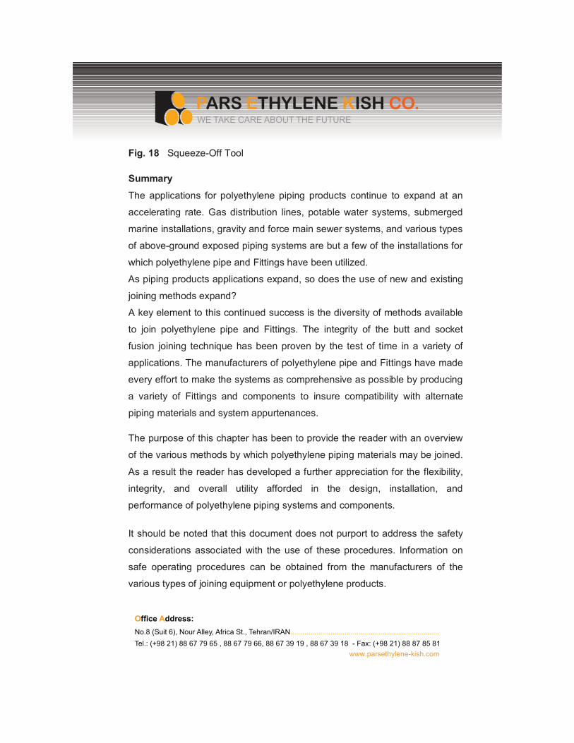
Fig. 18 Squeeze-Off Tool
Summary
The applications for polyethylene piping products continue to expand at an
accelerating rate. Gas distribution lines, potable water systems, submerged
marine installations, gravity and force main sewer systems, and various types
of above-ground exposed piping systems are but a few of the installations for
which polyethylene pipe and Fittings have been utilized.
As piping products applications expand, so does the use of new and existing
joining methods expand?
A key element to this continued success is the diversity of methods available
to join polyethylene pipe and Fittings. The integrity of the butt and socket
fusion joining technique has been proven by the test of time in a variety of
applications. The manufacturers of polyethylene pipe and Fittings have made
every effort to make the systems as comprehensive as possible by producing
a variety of Fittings and components to insure compatibility with alternate
piping materials and system appurtenances.
The purpose of this chapter has been to provide the reader with an overview
of the various methods by which polyethylene piping materials may be joined.
As a result the reader has developed a further appreciation for the flexibility,
integrity, and overall utility afforded in the design, installation, and
performance of polyethylene piping systems and components.
It should be noted that this document does not purport to address the safety
considerations associated with the use of these procedures. Information on
safe operating procedures can be obtained from the manufacturers of the
various types of joining equipment or polyethylene products.
O�����A����No.8 (Suit 6), Nour Alley, Africa St., Tehran/IRAN..........................................................................Tel.: (+98 21) 88 67 79 65 , 88 67 79 66, 88 67 39 19 , 88 67 39 18 - Fax: (+98 21) 88 87 85 81
www.parsethylene-kish.com
WE TAKE CARE ABOUT THE FUTURE
References
1. ASME/ANSI B16.5. (1996). American National Standard on Pipe
Flanges and Flanged Fittings, American National Standards Institute, New
York, NY.
2. ASTM D2513, Standard Specifications for Thermoplastic Gas
Pressure Pipe, Tubing, and Fittings, Annual Book of Standards, ASTM,
West Conshohocken, PA.
3. ASTM D2657, Standard Practice for Heat Fusion Joining of Polyolefin
Pipe and Fittings, Annual Book of Standards, ASTM, West Conshohocken,
PA.
4. ASTM D3140, Standard Practice for Flaring Polyolefin Pipe and
Tubing, Annual Book of Standards, ASTM, West Conshohocken, PA.
5. ASTM F894, Standard Specification for Polyethylene (PE) Large
Diameter Profile Wall Sewer and Drain Pipe, Annual Book of Standards,
ASTM, West Conshohocken, PA.
6. ASTM F1041, Standard Guide for Squeeze-Off of Polyolefin Gas
Pressure Pipe and Tubing, Annual Book of Standards, ASTM, West
Conshohocken, PA.
7. ASTM F1056, Standard Specification for Socket Fusion Tools for Use
in Socket Fusion Joining Polyethylene Pipe or Tubing and Fittings, ASTM,
West Conshohocken, PA.
8. AWWA C901, Polyethylene (PE) Pressure Pipe and Tubing, 1/2 in.
Through 3 in., for Water Service, American Water Works Association,
Denver, CO.
9. Caution Statement on Sidewall Heat Fusion Without Use of
Mechanical Assist Tooling, Statement T. Plastics Pipe Institute,
Washington, DC.
10. Code of Federal Regulations, Title 49, Part 192, Subpart F., Pipeline
Safety Regulations, Washington, DC.
11. General Guidelines for the Heat Fusion of Unlike Polyethylene Pipes
and Fittings, Report TN-13, Plastics Pipe Institute, Washington, DC.
12. IAPMO, International Association of Plumbing and Mechanical
Officials, Walnut, CA.
13. PPFA. Plastics Pipe and Fittings Association, Glen Ellyn, IL.
14. Victaulic General Catalog on Mechanical Piping Systems. (1988).
Victaulic Company of America, Easton, PA.
15. Generic Butt Fusion Procedure for Polyethylene Gas Pipe, PPI TR-33,
Plastics Pipe Institute, Inc., Washington, DC.
16. Generic Saddle Fusion Procedure for Polyethylene Gas Pipe, PPI TR-
41, Plastics Pipe Institute, Inc., Washington, DC.