Embed Size (px)
Citation preview
2.0 | March 2011 | 3725-76302-001D1
Polycom® DMA™ 7000 System Operations Guide
© 2009-2010 Polycom, Inc. All rights reserved.
Polycom, Inc.4750 Willow RoadPleasanton, CA 94588-2708USA
No part of this document may be reproduced or transmitted in any form or by any means, electronic or mechanical, for any purpose, without the express written permission of Polycom, Inc. Under the law, reproducing includes translating into another language or format.
As between the parties, Polycom, Inc., retains title to and ownership of all proprietary rights with respect to the software contained within its products. The software is protected by United States copyright laws and international treaty provision. Therefore, you must treat the software like any other copyrighted material (e.g., a book or sound recording).
Every effort has been made to ensure that the information in this manual is accurate. Polycom, Inc., is not responsible for printing or clerical errors. Information in this document is subject to change without notice.
ii
Trademark Information
Polycom®, the Polycom “Triangles” logo, and the names and marks associated with Polycom’s products are trademarks and/or service marks of Polycom, Inc., and are registered and/or common-law marks in the United States and various other countries.
All other trademarks are the property of their respective owners.
Java is a registered trademark of Oracle and/or its affiliates.
Patent Information
The accompanying product is protected by one or more U.S. and foreign patents and/or pending patent applications held by Polycom, Inc.
End User License Agreement
Use of this software constitutes acceptance of the terms and conditions of the Polycom DMA 7000 system end-user license agreement (EULA).
The EULA is included in the release notes document for your version, which is available on the Polycom Support page for the Polycom DMA 7000 system.
Polycom, Inc. iii
Contents
1 Polycom® DMA™ 7000 System Overview . . . . . . . . . . . . . 1Introduction to the Polycom DMA System . . . . . . . . . . . . . . . . . . . . . . . . . . . 1Polycom Solution Support . . . . . . . . . . . . . . . . . . . . . . . . . . . . . . . . . . . . . . . . . 3Working in the Polycom DMA System . . . . . . . . . . . . . . . . . . . . . . . . . . . . . . 3Open Source Software . . . . . . . . . . . . . . . . . . . . . . . . . . . . . . . . . . . . . . . . . . . . 6
2 Polycom® DMA™ System Initial Configuration Summary . . . 9Add DNS Records for Polycom DMA System . . . . . . . . . . . . . . . . . . . . . . . 10License the Polycom DMA System . . . . . . . . . . . . . . . . . . . . . . . . . . . . . . . . 10Configure Signaling . . . . . . . . . . . . . . . . . . . . . . . . . . . . . . . . . . . . . . . . . . . . . 11Set Up Security . . . . . . . . . . . . . . . . . . . . . . . . . . . . . . . . . . . . . . . . . . . . . . . . . 11Set Up MCUs . . . . . . . . . . . . . . . . . . . . . . . . . . . . . . . . . . . . . . . . . . . . . . . . . . . 12Connect to an Enterprise Directory . . . . . . . . . . . . . . . . . . . . . . . . . . . . . . . . 13Set Up Conference Templates . . . . . . . . . . . . . . . . . . . . . . . . . . . . . . . . . . . . . 14Test the System . . . . . . . . . . . . . . . . . . . . . . . . . . . . . . . . . . . . . . . . . . . . . . . . . 14
3 System Configuration . . . . . . . . . . . . . . . . . . . . . . . . . . . . 17Network . . . . . . . . . . . . . . . . . . . . . . . . . . . . . . . . . . . . . . . . . . . . . . . . . . . . . . . 17System Time . . . . . . . . . . . . . . . . . . . . . . . . . . . . . . . . . . . . . . . . . . . . . . . . . . . 19License and Capabilities . . . . . . . . . . . . . . . . . . . . . . . . . . . . . . . . . . . . . . . . . 20Signaling Configuration . . . . . . . . . . . . . . . . . . . . . . . . . . . . . . . . . . . . . . . . . . 21Logging Configuration . . . . . . . . . . . . . . . . . . . . . . . . . . . . . . . . . . . . . . . . . . 23History Record Retention . . . . . . . . . . . . . . . . . . . . . . . . . . . . . . . . . . . . . . . . 24CMA Integration . . . . . . . . . . . . . . . . . . . . . . . . . . . . . . . . . . . . . . . . . . . . . . . . 24Join CMA Dialog Box . . . . . . . . . . . . . . . . . . . . . . . . . . . . . . . . . . . . . . . . . . . . 26System Configuration Procedures . . . . . . . . . . . . . . . . . . . . . . . . . . . . . . . . . 26
Add Licenses . . . . . . . . . . . . . . . . . . . . . . . . . . . . . . . . . . . . . . . . . . . . . . . . 27Configure Signaling . . . . . . . . . . . . . . . . . . . . . . . . . . . . . . . . . . . . . . . . . 28Configure Logging . . . . . . . . . . . . . . . . . . . . . . . . . . . . . . . . . . . . . . . . . . 30Configure History Record Retention . . . . . . . . . . . . . . . . . . . . . . . . . . . 30Join or Leave a Polycom CMA System . . . . . . . . . . . . . . . . . . . . . . . . . . 31
DMA Operations Guide
iv Polycom, Inc.
4 System Security . . . . . . . . . . . . . . . . . . . . . . . . . . . . . . . . 33Management and Security Overview . . . . . . . . . . . . . . . . . . . . . . . . . . . . . . 33
How Certificates Work . . . . . . . . . . . . . . . . . . . . . . . . . . . . . . . . . . . . . . . 33Forms of Certificates Accepted by the Polycom DMA System . . . . . . 34How Certificates Are Used by the Polycom DMA System . . . . . . . . . 35Frequently Asked Questions . . . . . . . . . . . . . . . . . . . . . . . . . . . . . . . . . . . 36
Certificate Management . . . . . . . . . . . . . . . . . . . . . . . . . . . . . . . . . . . . . . . . . . 36Certificate Information Dialog Box . . . . . . . . . . . . . . . . . . . . . . . . . . . . . 37Certificate Signing Request Dialog Box . . . . . . . . . . . . . . . . . . . . . . . . . 38Install Certificates Dialog Box . . . . . . . . . . . . . . . . . . . . . . . . . . . . . . . . . 38Certificate Details Dialog Box . . . . . . . . . . . . . . . . . . . . . . . . . . . . . . . . . 39
Certificate Procedures . . . . . . . . . . . . . . . . . . . . . . . . . . . . . . . . . . . . . . . . . . . 39Install a Certificate Authority’s Certificate . . . . . . . . . . . . . . . . . . . . . . 40Create a Certificate Signing Request in the DMA System . . . . . . . . . . 41Install a Certificate in the DMA System . . . . . . . . . . . . . . . . . . . . . . . . . 42Remove a Certificate from the DMA System . . . . . . . . . . . . . . . . . . . . 43
Security Configuration . . . . . . . . . . . . . . . . . . . . . . . . . . . . . . . . . . . . . . . . . . . 44Session Configuration . . . . . . . . . . . . . . . . . . . . . . . . . . . . . . . . . . . . . . . . . . . 48Login Banner . . . . . . . . . . . . . . . . . . . . . . . . . . . . . . . . . . . . . . . . . . . . . . . . . . . 48
5 Device Management . . . . . . . . . . . . . . . . . . . . . . . . . . . . 51MCUs . . . . . . . . . . . . . . . . . . . . . . . . . . . . . . . . . . . . . . . . . . . . . . . . . . . . . . . . . 51
Add MCU Dialog Box . . . . . . . . . . . . . . . . . . . . . . . . . . . . . . . . . . . . . . . . 54Edit MCU Dialog Box . . . . . . . . . . . . . . . . . . . . . . . . . . . . . . . . . . . . . . . . 54MCU Procedures . . . . . . . . . . . . . . . . . . . . . . . . . . . . . . . . . . . . . . . . . . . . 55
MCU Zones . . . . . . . . . . . . . . . . . . . . . . . . . . . . . . . . . . . . . . . . . . . . . . . . . . . . 57Add MCU Zone Dialog Box . . . . . . . . . . . . . . . . . . . . . . . . . . . . . . . . . . . 58Edit MCU Zone Dialog Box . . . . . . . . . . . . . . . . . . . . . . . . . . . . . . . . . . . 59MCU Zone Procedures . . . . . . . . . . . . . . . . . . . . . . . . . . . . . . . . . . . . . . . 59
MCU Zone Orders . . . . . . . . . . . . . . . . . . . . . . . . . . . . . . . . . . . . . . . . . . . . . . 60Add MCU Zone Order Dialog Box . . . . . . . . . . . . . . . . . . . . . . . . . . . . . 62Edit MCU Zone Order Dialog Box . . . . . . . . . . . . . . . . . . . . . . . . . . . . . 63MCU Zone Order Procedures . . . . . . . . . . . . . . . . . . . . . . . . . . . . . . . . . 63
6 Conference Setup . . . . . . . . . . . . . . . . . . . . . . . . . . . . . . . 65Conference Templates . . . . . . . . . . . . . . . . . . . . . . . . . . . . . . . . . . . . . . . . . . . 65
Two Types of Templates . . . . . . . . . . . . . . . . . . . . . . . . . . . . . . . . . . . . . 65Template Priority . . . . . . . . . . . . . . . . . . . . . . . . . . . . . . . . . . . . . . . . . . . . 67About Conference IVR Services . . . . . . . . . . . . . . . . . . . . . . . . . . . . . . . 67
Contents
Polycom, Inc. v
About Cascading . . . . . . . . . . . . . . . . . . . . . . . . . . . . . . . . . . . . . . . . . . . . 68Conference Templates List . . . . . . . . . . . . . . . . . . . . . . . . . . . . . . . . . . . . 68Add Conference Template Dialog Box . . . . . . . . . . . . . . . . . . . . . . . . . . 69Edit Conference Template Dialog Box . . . . . . . . . . . . . . . . . . . . . . . . . . 74Select Layout Dialog Box . . . . . . . . . . . . . . . . . . . . . . . . . . . . . . . . . . . . . 79Conference Templates Procedures . . . . . . . . . . . . . . . . . . . . . . . . . . . . . 80
Conference Settings . . . . . . . . . . . . . . . . . . . . . . . . . . . . . . . . . . . . . . . . . . . . . 82Calendaring Service . . . . . . . . . . . . . . . . . . . . . . . . . . . . . . . . . . . . . . . . . . . . . 83
7 Enterprise Directory Integration . . . . . . . . . . . . . . . . . . . . 87Enterprise Directory . . . . . . . . . . . . . . . . . . . . . . . . . . . . . . . . . . . . . . . . . . . . . 87Enterprise Directory Integration Procedure . . . . . . . . . . . . . . . . . . . . . . . . . 92Understanding Base DN . . . . . . . . . . . . . . . . . . . . . . . . . . . . . . . . . . . . . . . . . 95Adding Passwords for Enterprise Users . . . . . . . . . . . . . . . . . . . . . . . . . . . . 97About the System’s Directory Queries . . . . . . . . . . . . . . . . . . . . . . . . . . . . . 99
8 Site Topology Configuration . . . . . . . . . . . . . . . . . . . . . . 105About Site Topology . . . . . . . . . . . . . . . . . . . . . . . . . . . . . . . . . . . . . . . . . . . . 105Sites . . . . . . . . . . . . . . . . . . . . . . . . . . . . . . . . . . . . . . . . . . . . . . . . . . . . . . . . . . 106
Site Information Dialog Box . . . . . . . . . . . . . . . . . . . . . . . . . . . . . . . . . . 106Add Site Dialog Box . . . . . . . . . . . . . . . . . . . . . . . . . . . . . . . . . . . . . . . . 107Edit Site Dialog Box . . . . . . . . . . . . . . . . . . . . . . . . . . . . . . . . . . . . . . . . . 107Add Subnet Dialog Box . . . . . . . . . . . . . . . . . . . . . . . . . . . . . . . . . . . . . 108Edit Subnet Dialog Box . . . . . . . . . . . . . . . . . . . . . . . . . . . . . . . . . . . . . . 108
Site Links . . . . . . . . . . . . . . . . . . . . . . . . . . . . . . . . . . . . . . . . . . . . . . . . . . . . . 109Add Site Link Dialog Box . . . . . . . . . . . . . . . . . . . . . . . . . . . . . . . . . . . . 109
Edit Site Link Dialog Box . . . . . . . . . . . . . . . . . . . . . . . . . . . . . . . . . . . . 109Site-to-Site Exclusions . . . . . . . . . . . . . . . . . . . . . . . . . . . . . . . . . . . . . . . . . . 110
Add Site-to-Site Exclusion Wizard . . . . . . . . . . . . . . . . . . . . . . . . . . . . 110Network Clouds . . . . . . . . . . . . . . . . . . . . . . . . . . . . . . . . . . . . . . . . . . . . . . . 111
Add MPLS Cloud Dialog Box . . . . . . . . . . . . . . . . . . . . . . . . . . . . . . . . 111Edit MPLS Cloud Dialog Box . . . . . . . . . . . . . . . . . . . . . . . . . . . . . . . . 112
Site Topology Configuration Procedures . . . . . . . . . . . . . . . . . . . . . . . . . . 112
9 Users and Groups . . . . . . . . . . . . . . . . . . . . . . . . . . . . . 115User Roles Overview . . . . . . . . . . . . . . . . . . . . . . . . . . . . . . . . . . . . . . . . . . . 116Adding Users Overview . . . . . . . . . . . . . . . . . . . . . . . . . . . . . . . . . . . . . . . . 117Users . . . . . . . . . . . . . . . . . . . . . . . . . . . . . . . . . . . . . . . . . . . . . . . . . . . . . . . . . 118
Add User Dialog Box . . . . . . . . . . . . . . . . . . . . . . . . . . . . . . . . . . . . . . . . 119
DMA Operations Guide
vi Polycom, Inc.
Edit User Dialog Box . . . . . . . . . . . . . . . . . . . . . . . . . . . . . . . . . . . . . . . . 121Conference Rooms Dialog Box . . . . . . . . . . . . . . . . . . . . . . . . . . . . . . . . 123Add Conference Room Dialog Box . . . . . . . . . . . . . . . . . . . . . . . . . . . . 125Edit Conference Room Dialog Box . . . . . . . . . . . . . . . . . . . . . . . . . . . . 126Users Procedures . . . . . . . . . . . . . . . . . . . . . . . . . . . . . . . . . . . . . . . . . . . 127Conference Rooms Procedures . . . . . . . . . . . . . . . . . . . . . . . . . . . . . . . 128
Groups . . . . . . . . . . . . . . . . . . . . . . . . . . . . . . . . . . . . . . . . . . . . . . . . . . . . . . . 130Import Enterprise Groups Dialog Box . . . . . . . . . . . . . . . . . . . . . . . . . 131Edit Group Dialog Box . . . . . . . . . . . . . . . . . . . . . . . . . . . . . . . . . . . . . . 131Enterprise Groups Procedures . . . . . . . . . . . . . . . . . . . . . . . . . . . . . . . 132
10 System Operations . . . . . . . . . . . . . . . . . . . . . . . . . . . . . 135Management and Maintenance Overview . . . . . . . . . . . . . . . . . . . . . . . . . 135
Administrator Responsibilities . . . . . . . . . . . . . . . . . . . . . . . . . . . . . . . 135Administrative Best Practices . . . . . . . . . . . . . . . . . . . . . . . . . . . . . . . . . 136Auditor Responsibilities . . . . . . . . . . . . . . . . . . . . . . . . . . . . . . . . . . . . . 136Auditor Best Practices . . . . . . . . . . . . . . . . . . . . . . . . . . . . . . . . . . . . . . . 137
Recommended Regular Maintenance . . . . . . . . . . . . . . . . . . . . . . . . . . . . . 137Dashboard . . . . . . . . . . . . . . . . . . . . . . . . . . . . . . . . . . . . . . . . . . . . . . . . . . . . 140Monitoring Login Sessions . . . . . . . . . . . . . . . . . . . . . . . . . . . . . . . . . . . . . . 144Change Password Dialog Box . . . . . . . . . . . . . . . . . . . . . . . . . . . . . . . . . . . . 144Tools . . . . . . . . . . . . . . . . . . . . . . . . . . . . . . . . . . . . . . . . . . . . . . . . . . . . . . . . . 145System Log Files . . . . . . . . . . . . . . . . . . . . . . . . . . . . . . . . . . . . . . . . . . . . . . . 147
System Logs Procedures . . . . . . . . . . . . . . . . . . . . . . . . . . . . . . . . . . . . . 148Backing Up and Restoring . . . . . . . . . . . . . . . . . . . . . . . . . . . . . . . . . . . . . . . 149
Backup and Restore Procedures . . . . . . . . . . . . . . . . . . . . . . . . . . . . . . . 150Upgrading the Software . . . . . . . . . . . . . . . . . . . . . . . . . . . . . . . . . . . . . . . . 153
Upgrade Procedures . . . . . . . . . . . . . . . . . . . . . . . . . . . . . . . . . . . . . . . . 154Adding a Second Server . . . . . . . . . . . . . . . . . . . . . . . . . . . . . . . . . . . . . . . . 157
Expanding an Unpatched System . . . . . . . . . . . . . . . . . . . . . . . . . . . . . 157Expanding a Patched System . . . . . . . . . . . . . . . . . . . . . . . . . . . . . . . . . 158
Replacing a Failed Server . . . . . . . . . . . . . . . . . . . . . . . . . . . . . . . . . . . . . . . 160Shutting Down and Restarting . . . . . . . . . . . . . . . . . . . . . . . . . . . . . . . . . . . 160
11 System Reports . . . . . . . . . . . . . . . . . . . . . . . . . . . . . . . 163Call History Report . . . . . . . . . . . . . . . . . . . . . . . . . . . . . . . . . . . . . . . . . . . . . 163
Call Events . . . . . . . . . . . . . . . . . . . . . . . . . . . . . . . . . . . . . . . . . . . . . . . . 164Property Changes . . . . . . . . . . . . . . . . . . . . . . . . . . . . . . . . . . . . . . . . . . 164
Conference History Report . . . . . . . . . . . . . . . . . . . . . . . . . . . . . . . . . . . . . . 165Associated Calls . . . . . . . . . . . . . . . . . . . . . . . . . . . . . . . . . . . . . . . . . . . . 165
Contents
Polycom, Inc. vii
Conference Events . . . . . . . . . . . . . . . . . . . . . . . . . . . . . . . . . . . . . . . . . . 166Property Changes . . . . . . . . . . . . . . . . . . . . . . . . . . . . . . . . . . . . . . . . . . 166
Export CDR Data . . . . . . . . . . . . . . . . . . . . . . . . . . . . . . . . . . . . . . . . . . . . . . 167Enterprise Directory Integration Report . . . . . . . . . . . . . . . . . . . . . . . . . . . 169Orphaned Groups and Users Report . . . . . . . . . . . . . . . . . . . . . . . . . . . . . . 171Conference Room Errors Report . . . . . . . . . . . . . . . . . . . . . . . . . . . . . . . . . 173Export Conference Room Errors Data . . . . . . . . . . . . . . . . . . . . . . . . . . . . . 175Enterprise Password Errors Report . . . . . . . . . . . . . . . . . . . . . . . . . . . . . . . 175Export Enterprise Password Errors Data . . . . . . . . . . . . . . . . . . . . . . . . . . 177
Index . . . . . . . . . . . . . . . . . . . . . . . . . . . . . . . . . . . . . . . 179

DMA Operations Guide
viii Polycom, Inc.
Polycom, Inc. 1
1Polycom® DMA™ 7000 System Overview
This chapter provides an overview of the Polycom® Distributed Media Application™ (DMA™) 7000 system. It includes these topics:
• Introduction to the Polycom DMA System
• Polycom Solution Support
• Working in the Polycom DMA System
• Open Source Software
Introduction to the Polycom DMA System The Polycom DMA system is a highly reliable and scalable multipoint conferencing solution based on the Polycom® Proxias™ application server. It uses advanced routing policies to distribute audio and video calls among multiple media servers (Multipoint Control Units, or MCUs), creating a single resource pool. The system acts much like a virtual MCU, greatly simplifying video conferencing resource management and improving efficiency.
The Polycom DMA system integrates with your enterprise directory, automating the task of provisioning users for video conferencing. Combined with its advanced resource management, this makes reservationless video conferencing on a large scale feasible and efficient, reducing or eliminating the need for conference scheduling.
The Polycom DMA system’s ability to handle multiple MCUs as a single resource pool makes it highly scalable. To expand the system, you can add MCUs on the fly without impacting end users and without requiring re-provisioning.
DMA Operations Guide Introduction to the Polycom DMA System
2 Polycom, Inc.
Two-node Cluster Configuration The two-server configuration of the Polycom DMA system is designed to have no single point of failure within the system that could cause the service to become unavailable. To support this, the system is configured as a cooperative active/active two-node cluster. Both servers are actively registered and can accept and process calls.
The H.323 network topology and choice of gatekeeper determine which server receives a call. When a Polycom CMA system is acting as the gatekeeper, it routes calls destined for the Polycom DMA system to the first server that it finds available. If the first server isn’t available, it automatically routes the call to the second server.
In the event of a single server (node) failure, two things happen:
• All current calls that are being routed through the failed node are terminated. These users simply need to redial the same number. The gatekeeper automatically routes them to the remaining Polycom DMA system server and they’re placed back into conference.
• If the failed server is the active web host for the system management interface, the active user interface sessions end, the web host address automatically migrates to the remaining server, and it becomes the active web host. Administrative users can then log back into the system at the same URL. The system can always be administered via the same address, regardless of which server is actually the web host.
The Polycom DMA system continuously monitors the used and available resources on each MCU. If an MCU suffers a catastrophic failure, the Polycom DMA system adjusts its internal resource counts. All the calls and conferences on the failed MCU are terminated. But as in a server failure, callers can dial back into the system using the exact same number that they used for their initial dial-in. The Polycom DMA system then relocates their new conference to the best available MCU (provided that there is still sufficient MCU capacity remaining in the system).
The internal databases within each Polycom DMA system server are fully replicated to the other node in the cluster. If a catastrophic failure of one of the database engines occurs, the system automatically switches itself over to use the database on the other server.
Single-server Configuration The Polycom DMA system is also available in a single-server configuration. This configuration offers all the advantages of the Polycom DMA system except the redundancy and fault tolerance at a lower price. It can be upgraded to a two-server configuration at any time.
This manual generally assumes a redundant two-node cluster. Where there are significant differences between the two configurations, those are spelled out.
Polycom Solution Support Polycom® DMA™ 7000 System Overview
Polycom, Inc. 3
Polycom Solution Support Polycom Implementation and Maintenance services provide support for Polycom solution components only. Additional services for supported third-party Unified Communications (UC) environments integrated with Polycom solutions are available from Polycom Global Services and its certified Partners. These additional services will help customers successfully design, deploy, optimize, and manage Polycom visual communications within their UC environments.
Professional Services for Microsoft Integration is mandatory for Polycom Conferencing for Microsoft Outlook and Microsoft Office Communications Server integrations. For additional information, please see http://www.polycom.com/services/professional_services/index.html or contact your local Polycom representative.
Working in the Polycom DMA System This section includes some general information you should know when working in the Polycom DMA system. It includes these topics:
• Polycom DMA System Management Interface Access
• Video Tour
• Field Input Requirements
• Settings Dialog Box
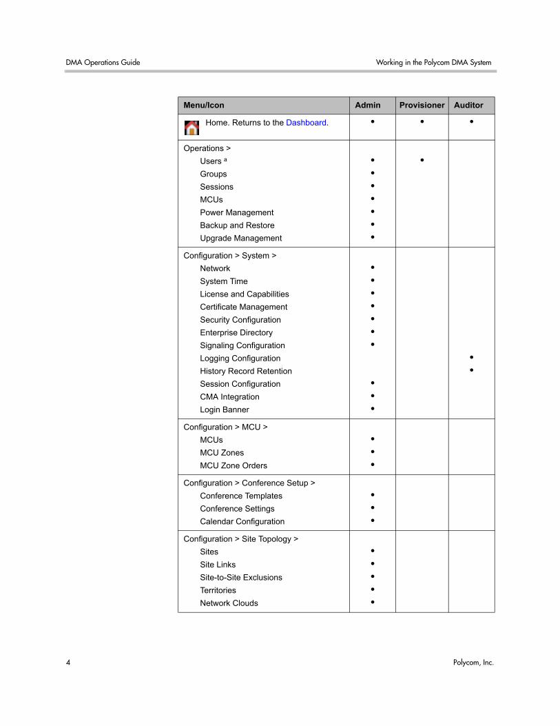
Polycom DMA System Management Interface Access The Polycom DMA system has three system user roles that provide access to the management and operations interface. The functions you can perform and parts of the interface you can access depend on your user role or roles:
DMA Operations Guide Working in the Polycom DMA System
4 Polycom, Inc.
Menu/Icon Admin Provisioner Auditor
Home. Returns to the Dashboard. • • •
Operations >
Users a
Groups
Sessions
MCUs
Power Management
Backup and Restore
Upgrade Management
•
•
•
•
•
•
•
•
Configuration > System >
Network
System Time
License and Capabilities
Certificate Management
Security Configuration
Enterprise Directory
Signaling Configuration
Logging Configuration
History Record Retention
Session Configuration
CMA Integration
Login Banner
•
•
•
•
•
•
•
•
•
•
•
•
Configuration > MCU >
MCUs
MCU Zones
MCU Zone Orders
•
•
•
Configuration > Conference Setup >
Conference Templates
Conference Settings
Calendar Configuration
•
•
•
Configuration > Site Topology >
Sites
Site Links
Site-to-Site Exclusions
Territories
Network Clouds
•
•
•
•
•
Working in the Polycom DMA System Polycom® DMA™ 7000 System Overview
Polycom, Inc. 5
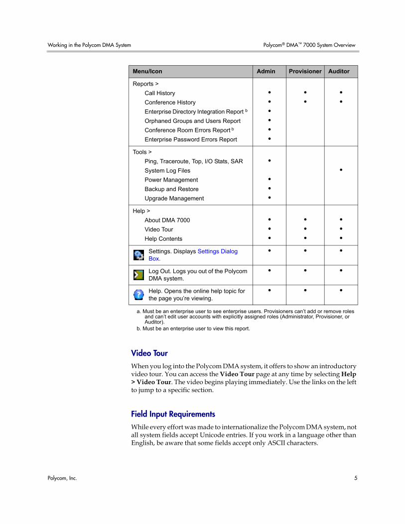
Video Tour When you log into the Polycom DMA system, it offers to show an introductory video tour. You can access the Video Tour page at any time by selecting Help > Video Tour. The video begins playing immediately. Use the links on the left to jump to a specific section.
Field Input Requirements While every effort was made to internationalize the Polycom DMA system, not all system fields accept Unicode entries. If you work in a language other than English, be aware that some fields accept only ASCII characters.
Reports >
Call History
Conference History
Enterprise Directory Integration Report b
Orphaned Groups and Users Report
Conference Room Errors Report b
Enterprise Password Errors Report
•
•
•
•
•
•
•
•
•
•
Tools >
Ping, Traceroute, Top, I/O Stats, SAR
System Log Files
Power Management
Backup and Restore
Upgrade Management
•
•
•
•
•
Help >
About DMA 7000
Video Tour
Help Contents
•
•
•
•
•
•
•
•
•
Settings. Displays Settings Dialog Box.
• • •
Log Out. Logs you out of the Polycom DMA system.
• • •
Help. Opens the online help topic for the page you’re viewing.
• • •
a. Must be an enterprise user to see enterprise users. Provisioners can’t add or remove roles and can’t edit user accounts with explicitly assigned roles (Administrator, Provisioner, or Auditor).
b. Must be an enterprise user to view this report.
Menu/Icon Admin Provisioner Auditor
DMA Operations Guide Open Source Software
6 Polycom, Inc.
Settings Dialog Box The Settings dialog box shows you your user name and information about the server you’re logged into. In addition, you can change the text size used in the Polycom DMA system interface. Note that larger text sizes will affect how much you can see in a given window or screen size and may require frequent scrolling.
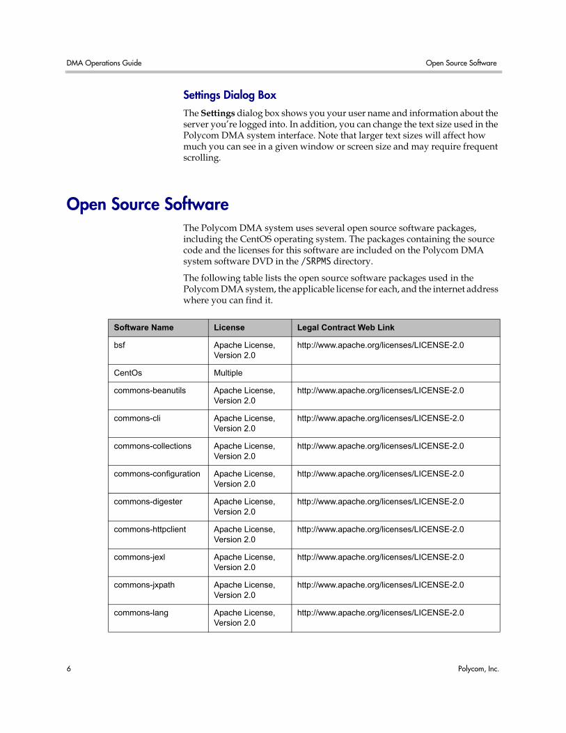
Open Source Software The Polycom DMA system uses several open source software packages, including the CentOS operating system. The packages containing the source code and the licenses for this software are included on the Polycom DMA system software DVD in the /SRPMS directory.
The following table lists the open source software packages used in the Polycom DMA system, the applicable license for each, and the internet address where you can find it.
Software Name License Legal Contract Web Link
bsf Apache License, Version 2.0
http://www.apache.org/licenses/LICENSE-2.0
CentOs Multiple
commons-beanutils Apache License, Version 2.0
http://www.apache.org/licenses/LICENSE-2.0
commons-cli Apache License, Version 2.0
http://www.apache.org/licenses/LICENSE-2.0
commons-collections Apache License, Version 2.0
http://www.apache.org/licenses/LICENSE-2.0
commons-configuration Apache License, Version 2.0
http://www.apache.org/licenses/LICENSE-2.0
commons-digester Apache License, Version 2.0
http://www.apache.org/licenses/LICENSE-2.0
commons-httpclient Apache License, Version 2.0
http://www.apache.org/licenses/LICENSE-2.0
commons-jexl Apache License, Version 2.0
http://www.apache.org/licenses/LICENSE-2.0
commons-jxpath Apache License, Version 2.0
http://www.apache.org/licenses/LICENSE-2.0
commons-lang Apache License, Version 2.0
http://www.apache.org/licenses/LICENSE-2.0
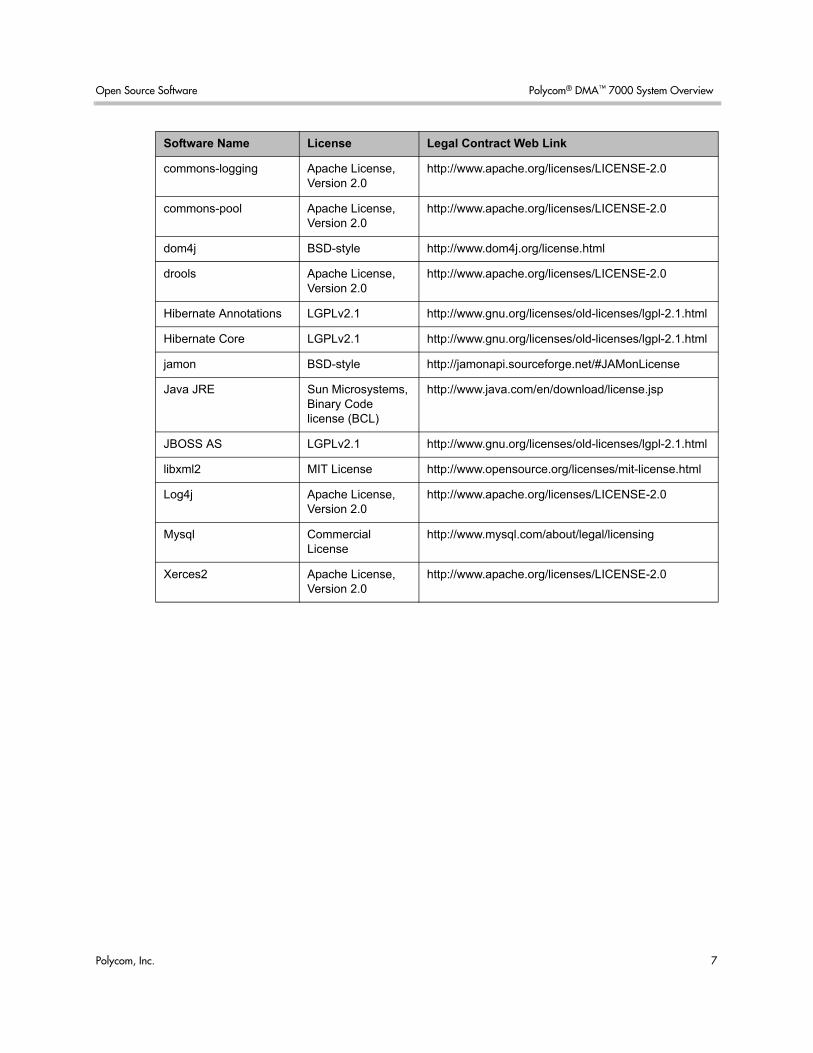
Open Source Software Polycom® DMA™ 7000 System Overview
Polycom, Inc. 7
commons-logging Apache License, Version 2.0
http://www.apache.org/licenses/LICENSE-2.0
commons-pool Apache License, Version 2.0
http://www.apache.org/licenses/LICENSE-2.0
dom4j BSD-style http://www.dom4j.org/license.html
drools Apache License, Version 2.0
http://www.apache.org/licenses/LICENSE-2.0
Hibernate Annotations LGPLv2.1 http://www.gnu.org/licenses/old-licenses/lgpl-2.1.html
Hibernate Core LGPLv2.1 http://www.gnu.org/licenses/old-licenses/lgpl-2.1.html
jamon BSD-style http://jamonapi.sourceforge.net/#JAMonLicense
Java JRE Sun Microsystems, Binary Code license (BCL)
http://www.java.com/en/download/license.jsp
JBOSS AS LGPLv2.1 http://www.gnu.org/licenses/old-licenses/lgpl-2.1.html
libxml2 MIT License http://www.opensource.org/licenses/mit-license.html
Log4j Apache License, Version 2.0
http://www.apache.org/licenses/LICENSE-2.0
Mysql Commercial License
http://www.mysql.com/about/legal/licensing
Xerces2 Apache License, Version 2.0
http://www.apache.org/licenses/LICENSE-2.0
Software Name License Legal Contract Web Link

DMA Operations Guide Open Source Software
8 Polycom, Inc.
Polycom, Inc. 9
2Polycom® DMA™ System Initial Configuration Summary
This chapter describes the configuration tasks required to complete your implementation of a new Polycom® Distributed Media Application™ (DMA™) 7000 system once installation and initial network configuration are complete.
This chapter assumes you’ve completed the Getting Started Guide’s server configuration procedure, logged into the Polycom DMA system’s management interface, and verified that the Network Status section of the Dashboard shows (for a two-server configuration) two cluster members, with healthy enterprise and private network status for both.
Initial configuration includes the following topics:
System configuration
• Add DNS Records for Polycom DMA System
• License the Polycom DMA System
• Configure Signaling
• Set Up Security
• Set Up MCUs
• Connect to an Enterprise Directory
• Set Up Conference Templates
Confirming configuration
• Test the System
Each topic describes the task, provides background and overview information for it, and where appropriate, links to specific step-by-step procedures to follow in order to complete the task.
DMA Operations Guide Add DNS Records for Polycom DMA System
10 Polycom, Inc.
Add DNS Records for Polycom DMA System In order to access your Polycom DMA system by name instead of by IP address, you must create an alias record (or A record) on your DNS server.
For a two-node cluster configuration, at a minimum, create a record for the virtual IP address assigned to the Polycom DMA system. We recommend that you create an alias record for each of the system’s three IP addresses.
The DNS server(s) should also have entries for your Active Directory server (if different from the DNS server) and gatekeeper.
License the Polycom DMA System The Polycom DMA system license you purchased specifies how many and what type of MCUs the system can use as conferencing resources. You should have received either one or two license numbers, depending on whether you ordered a single-server system or a two-server cluster.
You must obtain an activation key code for each server from the Polycom Resource Center. You enter the server’s serial number and the license number that you were given for that server, and the PRC generates an activation key for that server. For a cluster, you repeat the process using the other server’s serial number and its license number. Installing the activation keys activates the licenses for your system.
To activate the system license, follow the procedure in “License and Capabilities” on page 20.
Note These topics outline the configuration tasks that are generally required. You may wish to complete other optional configuration tasks, including:
• Integrate with a Polycom CMA system (see “CMA Integration” on page 24) or enter site topology information (see “Site Topology Configuration” on page 105).
• Enable cascading of conferences (see “About Cascading” on page 68).
• Configure calendaring service (“Calendaring Service” on page 83).
Caution An activation key is linked to a specific server’s serial number. For a two-server cluster, you must generate the activation key for each server using that server’s serial number. Licensing will fail if you generate both activation keys from the same server serial number.
Configure Signaling Polycom® DMA™ System Initial Configuration Summary
Polycom, Inc. 11
Configure Signaling Signaling setup includes enabling H.323, SIP, or both, registering with an H.323 gatekeeper, and setting the prefix for dialing into the system. The Polycom DMA system must be registered with a gatekeeper.
When you configure a two-node Polycom DMA system to use a gatekeeper, each node in the cluster independently registers its IP address with the gatekeeper, using the configured prefix as a service registration.
Once registration is complete, the Polycom DMA system is ready to receive calls using H.323 alias or H.264 addressing.
On the gatekeeper, the two nodes of the system appear as two MCUs using the same prefix.
To configure signaling, follow the procedure in “Signaling Configuration” on page 21.
Set Up Security The first step in securing your Polycom DMA system is to locate it in a secure data center with controlled access, but that topic is beyond the scope of this document.
Secure setup of the Polycom DMA system consists of the following high-level tasks (some of which overlap with subsequent initial setup topics):
1 As the default local administrative user (admin), create a local user account for yourself with the Administrator role, log in using that account, and delete the admin user account. See “Adding Users Overview” on page 117 and “Users Procedures” on page 127.
2 Integrate with the enterprise directory, assign the Administrator role to your named enterprise account, and remove the Polycom DMA system’s user roles (see “User Roles Overview” on page 116) from the service account used to integrate with the enterprise directory. See “Connect to an Enterprise Directory” on page 13 and “Enterprise Directory” on page 87.
3 Log out and log back in using your enterprise user ID and password.
4 Verify that the expected enterprise users are available in the Polycom DMA system and that conference room IDs were successfully created for them. If necessary, adjust enterprise integration settings and correct errors. See “Enterprise Directory” on page 87, “Users Procedures” on page 127, and “Conference Room Errors Report” on page 173.
5 Obtain and install a security certificate from a trusted certificate authority. See “Management and Security Overview” on page 33 and “Certificate Procedures” on page 39.
DMA Operations Guide Set Up MCUs
12 Polycom, Inc.
6 Temporarily enable console access, change the default root password, and then set the system to the recommended maximum security mode. See “Security Configuration” on page 44.
7 Document your current configuration for comparison in the future. We recommend saving screen captures of all the configuration pages.
8 Manually create a backup, download it, and store it in a safe place. See “Backing Up and Restoring” on page 149.
Set Up MCUs Make sure your RMX MCUs are configured to accept encrypted (HTTPS) management connections (required for maximum security mode) and add them to the Polycom DMA system. See “Device Management” on page 51.
The Polycom DMA system uses conference templates to define the conferencing experience associated with a conference room or enterprise group. You can create standalone templates (recommended), setting the conferencing parameters directly in the Polycom DMA system, or link templates to RMX conference profiles (see “Conference Templates” on page 65).
Both methods allow you to specify most conference parameters:
• General information such as line rate, encryption, auto termination, and H.239 settings
• Video settings such as mode (presentation or lecture) and layout
• IVR settings
• Conference recording settings
If you want to create DMA system templates linked to conference profiles on the RMX MCUs, make sure the profiles used by the Polycom DMA system exist on all the RMX MCUs and are defined the same on all of them.
Note The currently installed license determines the number and type of MCUs that the Polycom DMA system can properly provision and communicate with.
Connect to an Enterprise Directory Polycom® DMA™ System Initial Configuration Summary
Polycom, Inc. 13
Connect to an Enterprise Directory Connecting to an enterprise directory (Microsoft Active Directory is currently supported) simplifies the task of deploying conferencing to a large organization. All Polycom DMA system access to the enterprise directory is read-only and minimally impacts the directory performance. See “Enterprise Directory” on page 87.
Before integrating with the enterprise directory, be sure that one or more DNS servers are specified (this should have been done during installation and initial setup). See “Network” on page 17.
Enterprise directory integration automatically makes the enterprise users (directory members) into Conferencing Users in the Polycom DMA system, and can assign each of them a conference room (virtual meeting room). The conference room IDs are typically generated from the enterprise users’ phone numbers.
Once the Polycom DMA system is integrated with an enterprise directory, it reads the directory information daily, so that user and group information is updated automatically as people join and leave the organization. The system caches the data from the enterprise directory. Between updates, it needs to access the directory only to authenticate passwords; all other user information (such as user search results) comes from its cache.
Enterprise groups can have their own conference templates that provide a custom conferencing experience (see “Conference Templates” on page 65). They can also have their own MCU zone order, which preferentially routes conferences to certain MCUs (see “MCU Zone Orders” on page 60).
You can assign Polycom DMA system roles to an enterprise group, applying the roles to all members of the group and enabling them to log into the Polycom DMA system’s management interface with their standard network user names and passwords.
See “User Roles Overview” on page 116, “Groups” on page 130, and “Enterprise Groups Procedures” on page 132.
Note If you’re not knowledgeable about enterprise directories in general and your specific implementation in particular, please consult with someone who is. Enterprise directory integration is a non-trivial matter that should have been thoroughly discussed and planned for prior to system installation.
Note Creating conference rooms (virtual meeting rooms) for enterprise users is optional. If you want to integrate with the enterprise directory to load user and group information into the Polycom DMA system, but don’t want to give all users the ability to host conferences, you can do so. Then you can manually add conference rooms for selected users. See “Conference Rooms Procedures” on page 128.
DMA Operations Guide Set Up Conference Templates
14 Polycom, Inc.
There are security concerns that need to be addressed regarding user accounts, whether local or enterprise. See the high-level process described in “Set Up Security” on page 11.
Set Up Conference Templates The Polycom DMA system uses conference templates and global conference settings to manage system and conference behavior, and it has a default conference template and default global conference settings.
After you’ve added MCUs to the system, you may want to change the global conference settings or create additional templates that specify different conference properties.
If you integrate with an enterprise directory, you can use templates to provide customized conferencing experiences for various enterprise groups.
When you add a custom conference room to a user (either local or enterprise), you can choose which template that conference room uses.
To add conference templates, see “Conference Templates Procedures” on page 80. To change conference settings, see “Conference Settings” on page 82. To customize the conferencing experience for an enterprise group, see “Enterprise Groups Procedures” on page 132.
Test the System On the Dashboard, verify that:
• The MCUs section lists all the MCUs you added, and they’re all connected and in service.
• The Gatekeeper Status section indicates the system is properly registered with the gatekeeper.
• The Network Status section shows that:
— For a two-node cluster, there are two cluster members and that all four network interfaces are up (green up arrow) and in full duplex mode, with the private network speed at 1000 Mbps and the enterprise network speed correct for your network
— For a single-node system, there is one cluster member and that the single network interface is up (green up arrow) and in full duplex mode, with the speed correct for your enterprise network
• The System Information section’s details look correct, including the time, enterprise directory status and conference room count, and custom conference room count.
Test the System Polycom® DMA™ System Initial Configuration Summary
Polycom, Inc. 15
Set up some multipoint conferences by having endpoints dial into enterprise users’ conference rooms (preferably including a custom conference room). Verify that conferencing works satisfactorily, that the system status is good, and that the Dashboard accurately presents the status.
When you’re satisfied that the Polycom DMA system is configured and working properly, manually create a backup, download it, and store it in a safe place. See “Backing Up and Restoring” on page 149.

DMA Operations Guide Test the System
16 Polycom, Inc.
Polycom, Inc. 17
3System Configuration
This chapter describes the following Polycom® Distributed Media Application™ (DMA™) 7000 system configuration topics:
• Network
• System Time
• License and Capabilities
• Signaling Configuration
• Logging Configuration
• History Record Retention
• CMA Integration
• System Configuration Procedures
If you’re performing the initial configuration of your Polycom DMA system, study Chapter 2, “Polycom® DMA™ System Initial Configuration Summary,” before you continue.
Network The following table describes the fields on the Network page. These values are normally set in the USB Configuration Utility during system installation and rarely need to be changed. See the Getting Started Guide.
Caution Changing network settings requires a system restart and terminates all active conferences.
DMA Operations Guide Network
18 Polycom, Inc.
Note You can’t change the system’s network settings while it’s integrated with a Polycom CMA system. The integration must first be terminated. If you try to change network settings while integrated with a Polycom CMA system, the system asks if you want to terminate the integration. If you agree to do so, the system logs you out, terminates the integration, and restarts. Then you can log back in and change network settings.
Alternatively, you can terminate the integration manually before changing network settings. See “CMA Integration” on page 24.
Table 3-1 Fields on the Network page
Field Description
Node 1 Host name and IP address of the primary node.
Host names may contain only letters, numbers, and internal dashes (hyphens), and may not include a domain.
IP addresses must be standard dotted quads.
Node 2 Host name and IP address of the secondary node.
Virtual Virtual host name and IP address.
System domain Fully qualified domain name.
Subnet mask Subnetwork mask.
Default gateway IP address of gateway server for the subnetwork.
Primary DNS server IP address of domain name server. We strongly recommend specifying at least one DNS server. A DNS server must be specified in order to connect to the enterprise directory. See “Enterprise Directory” on page 87.
Secondary DNS server IP address of another domain name server.
Tertiary DNS server IP address of another domain name server.
DNS search domains One or more fully qualified domain names, separated by commas or spaces. The system domain you entered is added automatically, so you need not enter it.
System Time System Configuration
Polycom, Inc. 19
See also:
“System Time” on page 19
“License and Capabilities” on page 20
“Signaling Configuration” on page 21
“Logging Configuration” on page 23
“History Record Retention” on page 24
“CMA Integration” on page 24
“System Configuration Procedures” on page 26
System Time The following table describes the fields on the System Time page. These values are normally set in the USB Configuration Utility during system installation and rarely need to be changed. See the Getting Started Guide.
Caution Changing time settings requires a system restart and terminates all active conferences.
Table 3-2 Fields on the System Time page
Field Description
System time zone Time zone in which the system is located.
Auto adjust for Daylight Saving Time
Leave this checked to avoid a number of potential issues.
Date We don’t recommend setting time and date manually.
Time
NTP Servers Specify up to three time servers for maintaining system time (we recommend three). Enter IP addresses or, if DNS servers are specified, fully qualified domain names.
DMA Operations Guide License and Capabilities
20 Polycom, Inc.
See also:
“Network” on page 17
“License and Capabilities” on page 20
“Signaling Configuration” on page 21
“Logging Configuration” on page 23
“History Record Retention” on page 24
“CMA Integration” on page 24
“System Configuration Procedures” on page 26
License and Capabilities The Polycom DMA system is licensed for the types and maximum number of MCUs it can use and for the capabilities that may be enabled.
The following table describes the fields on the License and Capabilities page.
Table 3-3 Fields on the License and Capabilities page
Field Description
Active License
Licensed number of MCUs
The maximum number of MCUs that the Polycom DMA system can use as conferencing resources.
Licensed MCU types The types of MCUs that the Polycom DMA system can use as conferencing resources.
Activation Keys
A two-server system has two sets of the fields below, one for each node in the cluster.
System serial number The serial number of the specified server.
Activation key The activation key you received from Polycom for this server. The key for each server must be the correct one for that server’s serial number.
Signaling Configuration System Configuration
Polycom, Inc. 21
See also:
“Network” on page 17
“System Time” on page 19
“Signaling Configuration” on page 21
“Logging Configuration” on page 23
“History Record Retention” on page 24
“CMA Integration” on page 24
“System Configuration Procedures” on page 26
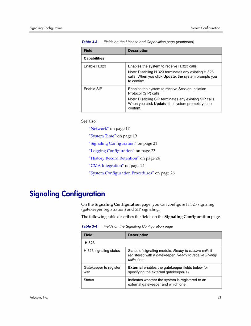
Signaling Configuration On the Signaling Configuration page, you can configure H.323 signaling (gatekeeper registration) and SIP signaling.
The following table describes the fields on the Signaling Configuration page.
Capabilities
Enable H.323 Enables the system to receive H.323 calls.
Note: Disabling H.323 terminates any existing H.323 calls. When you click Update, the system prompts you to confirm.
Enable SIP Enables the system to receive Session Initiation Protocol (SIP) calls.
Note: Disabling SIP terminates any existing SIP calls. When you click Update, the system prompts you to confirm.
Table 3-3 Fields on the License and Capabilities page (continued)
Field Description
Table 3-4 Fields on the Signaling Configuration page
Field Description
H.323
H.323 signaling status Status of signaling module. Ready to receive calls if registered with a gatekeeper, Ready to receive IP-only calls if not.
Gatekeeper to register with
External enables the gatekeeper fields below for specifying the external gatekeeper(s).
Status Indicates whether the system is registered to an external gatekeeper and which one.
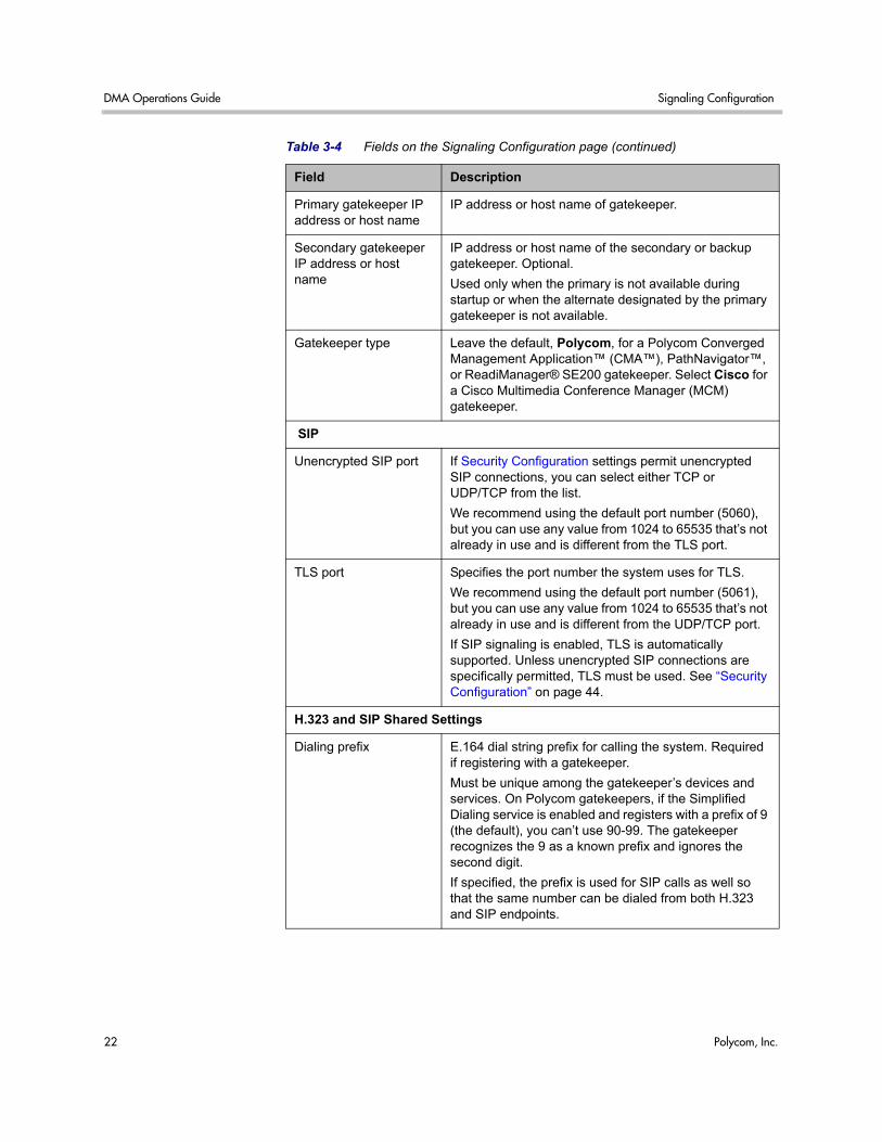
DMA Operations Guide Signaling Configuration
22 Polycom, Inc.
Primary gatekeeper IP address or host name
IP address or host name of gatekeeper.
Secondary gatekeeper IP address or host name
IP address or host name of the secondary or backup gatekeeper. Optional.
Used only when the primary is not available during startup or when the alternate designated by the primary gatekeeper is not available.
Gatekeeper type Leave the default, Polycom, for a Polycom Converged Management Application™ (CMA™), PathNavigator™, or ReadiManager® SE200 gatekeeper. Select Cisco for a Cisco Multimedia Conference Manager (MCM) gatekeeper.
SIP
Unencrypted SIP port If Security Configuration settings permit unencrypted SIP connections, you can select either TCP or UDP/TCP from the list.
We recommend using the default port number (5060), but you can use any value from 1024 to 65535 that’s not already in use and is different from the TLS port.
TLS port Specifies the port number the system uses for TLS.
We recommend using the default port number (5061), but you can use any value from 1024 to 65535 that’s not already in use and is different from the UDP/TCP port.
If SIP signaling is enabled, TLS is automatically supported. Unless unencrypted SIP connections are specifically permitted, TLS must be used. See “Security Configuration” on page 44.
H.323 and SIP Shared Settings
Dialing prefix E.164 dial string prefix for calling the system. Required if registering with a gatekeeper.
Must be unique among the gatekeeper’s devices and services. On Polycom gatekeepers, if the Simplified Dialing service is enabled and registers with a prefix of 9 (the default), you can’t use 90-99. The gatekeeper recognizes the 9 as a known prefix and ignores the second digit.
If specified, the prefix is used for SIP calls as well so that the same number can be dialed from both H.323 and SIP endpoints.
Table 3-4 Fields on the Signaling Configuration page (continued)
Field Description
Logging Configuration System Configuration
Polycom, Inc. 23
See also:
“Network” on page 17
“System Time” on page 19
“License and Capabilities” on page 20
“Logging Configuration” on page 23
“History Record Retention” on page 24
“CMA Integration” on page 24
“System Configuration Procedures” on page 26
Logging Configuration The following table describes the fields on the Logging Configuration page.
See also:
“Network” on page 17
“System Time” on page 19
“License and Capabilities” on page 20
“Signaling Configuration” on page 21
“History Record Retention” on page 24
“CMA Integration” on page 24
“System Configuration Procedures” on page 26
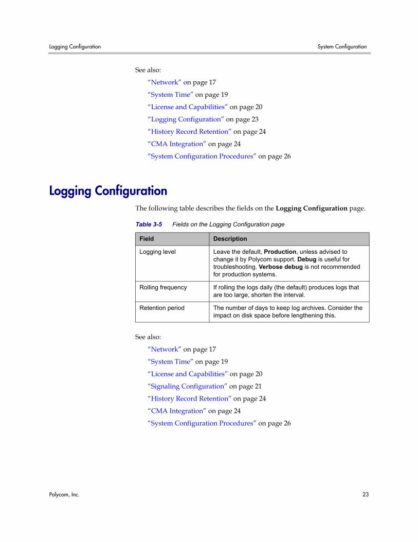
Table 3-5 Fields on the Logging Configuration page
Field Description
Logging level Leave the default, Production, unless advised to change it by Polycom support. Debug is useful for troubleshooting. Verbose debug is not recommended for production systems.
Rolling frequency If rolling the logs daily (the default) produces logs that are too large, shorten the interval.
Retention period The number of days to keep log archives. Consider the impact on disk space before lengthening this.
DMA Operations Guide History Record Retention
24 Polycom, Inc.
History Record Retention The following table describes the fields on the History Record Retention page.
See also:
“Network” on page 17
“System Time” on page 19
“License and Capabilities” on page 20
“Signaling Configuration” on page 21
“Logging Configuration” on page 23
“CMA Integration” on page 24
“System Configuration Procedures” on page 26
CMA Integration Integrating with a Polycom CMA 5000 system provides the Polycom DMA system with site topology information, which is necessary in order to support cascading of conferences (see “Add Conference Template Dialog Box” on page 69).
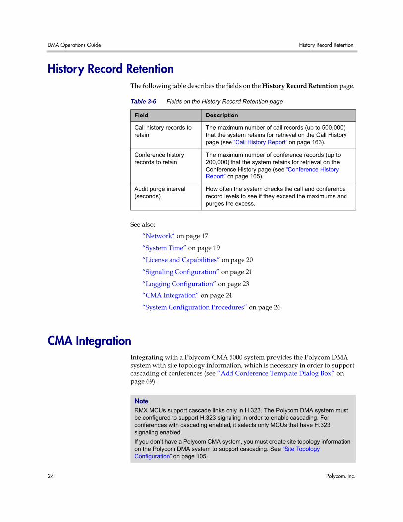
Table 3-6 Fields on the History Record Retention page
Field Description
Call history records to retain
The maximum number of call records (up to 500,000) that the system retains for retrieval on the Call History page (see “Call History Report” on page 163).
Conference history records to retain
The maximum number of conference records (up to 200,000) that the system retains for retrieval on the Conference History page (see “Conference History Report” on page 165).
Audit purge interval (seconds)
How often the system checks the call and conference record levels to see if they exceed the maximums and purges the excess.
Note RMX MCUs support cascade links only in H.323. The Polycom DMA system must be configured to support H.323 signaling in order to enable cascading. For conferences with cascading enabled, it selects only MCUs that have H.323 signaling enabled.
If you don’t have a Polycom CMA system, you must create site topology information on the Polycom DMA system to support cascading. See “Site Topology Configuration” on page 105.
CMA Integration System Configuration
Polycom, Inc. 25
The CMA Integration page contains the Join CMA command, which you use to integrate with your Polycom CMA system. When the system is integrated with a Polycom CMA system, it contains the Leave CMA command, which you use to terminate the integration.
When integrated, in addition to the site topology information, the system receives information about the CMA system. That information is displayed in the list on this page.
The following table describes the fields in the list.
See also:
“Network” on page 17
“System Time” on page 19
“License and Capabilities” on page 20
“Signaling Configuration” on page 21
“Logging Configuration” on page 23
“History Record Retention” on page 24
“System Configuration Procedures” on page 26
Caution Integrating with a Polycom CMA system or terminating the integration requires a system restart and terminates all active conferences.
Only a single Polycom DMA system can be integrated with a Polycom CMA system.
Table 3-7 Fields in the CMA Integration list
Field Description
Host name Name of the system.
IP Address IP address of the system.
Model Type of system (CMA 5000).
Version Software version of the system.
Status Status of last attempt to contact system (OK or Unreachable).
Time Time of last attempt to contact system.
DMA Operations Guide Join CMA Dialog Box
26 Polycom, Inc.
Join CMA Dialog Box Lets you integrate the Polycom DMA system with a Polycom CMA system to obtain site topology information. Site topology information is necessary in order to support cascading of conferences (see “Add Conference Template Dialog Box” on page 69).
The following table describes the fields in the dialog box.
See also:
“CMA Integration” on page 24
“System Configuration Procedures” on page 26
System Configuration Procedures This section describes the following Polycom® Distributed Media Application™ (DMA™) 7000 system configuration procedures:
• Add Licenses
• Configure Signaling
• Configure Logging
• Configure History Record Retention
• Join or Leave a Polycom CMA System
If you’re performing the initial configuration of your Polycom DMA system, study Chapter 2, “Polycom® DMA™ System Initial Configuration Summary,” before you continue. Other tasks are required that are described elsewhere.
Caution Integrating with a Polycom CMA system or terminating the integration requires a system restart and terminates all active conferences. Only a single Polycom DMA system can be integrated with a Polycom CMA system.
Table 3-8 Join CMA dialog box
Field Description
Host name or IP address
The Polycom CMA system with which to integrate.
User name Administrative user ID with which the Polycom DMA system can log into the Polycom CMA system.
Password Password for the administrative user ID.
System Configuration Procedures System Configuration
Polycom, Inc. 27
Add Licenses Adding licenses to your Polycom DMA system is a two-step process:
• Request a software activation key code for each server.
• Enter the activation key codes into the system.
The procedures below describe the process.
To request a software activation key code for each server
1 Log into the Polycom DMA system as an administrator and go to Configuration > System > License and Capabilities.
2 Record the serial number for each Polycom DMA server:
Server A: ____________________________
Server B: ____________________________ (none for single-server system)
3 Go to http://www.polycom.com/activation.
4 If you don’t already have one, register for an account. Then log in.
5 Select Product Activation.
6 In the License Number field, enter the software license number listed on the first (or only) server’s License Certificate (shipped with the product).
7 In the Serial Number field, enter the first (or only) server’s serial number (which you recorded in step 2).
8 Click Generate.
9 When the activation key for the first (or only) server appears, record it:
Server A: __________-__________-_________-___________
10 If you have a single-server Polycom DMA system, you’re finished with this procedure. Continue to the next procedure.
11 If you have a two-server cluster, repeat steps 6–8, this time entering the second license number you received and the second server’s serial number (also recorded in step 2).
12 Click Generate.
13 When the activation key for the second server appears, record it:
Server B: __________-__________-_________-___________
Caution An activation key is linked to a specific server’s serial number. For a two-server cluster, you must generate the activation key for each server using that server’s serial number. Licensing will fail if you generate both activation keys from the same server serial number.
DMA Operations Guide System Configuration Procedures
28 Polycom, Inc.
To enter license activation key codes and enable capabilities
1 Go to Configuration > System > License and Capabilities.
2 In the Activation key field for the first (or only) server, enter the activation key code that was generated for that server’s serial number.
3 If you have a two-server cluster, in the Activation key field for the second server, enter the activation key code that was generated for that server’s serial number.
4 Under Capabilities, select one or both of the protocols.
5 Click Update License.
A dialog box informs you that the licenses have been updated.
6 Click OK.
See also:
“License and Capabilities” on page 20
Configure Signaling
To configure signaling
1 If you’re going to register with a gatekeeper, verify on the gatekeeper that the H.323 prefix you want to use is available.
If you register with a prefix that’s already in use, you receive no warning that something is wrong, but calls to the system will fail.
2 On the Polycom DMA system, go to Configuration > System > License and Capabilities and ensure that Enable H.323 is checked. If you want to make the system accessible from SIP endpoints, make sure Enable SIP is also checked. If necessary, click Update Capabilities.
These capabilities must be available under your license. If they aren’t, contact your Polycom support or sales representative about obtaining a new license.
3 Go to Configuration > System > Signaling Configuration.
4 To set up H.323 access via a gatekeeper:
a Set Gatekeeper to register with. to External to register with an external gatekeeper as the primary gatekeeper.
Caution An activation key is linked to a specific server’s serial number. Each Activation Key field is labeled with a serial number. For a two-server cluster, make sure that the activation key code you enter for each server is the correct one for that server’s serial number.
System Configuration Procedures System Configuration
Polycom, Inc. 29
b Enter the IP address or host name for the primary gatekeeper.
c Enter the IP address or host name for the secondary gatekeeper (optional).
d If registering with a a Cisco Multimedia Conference Manager (MCM) gatekeeper, set Gatekeeper type to Cisco.
5 To set up SIP access:
a If the system’s security settings permit unencrypted SIP connections, optionally select TCP or UDP/TCP from the list.
You must have the Administrator role to change security settings. See “Security Configuration” on page 44.
b Leave the default port numbers (5060 for TCP/UDP, 5061 for TLS) unless you have a good reason for changing them.
6 Enter the dialing prefix to be used to reach the Polycom DMA system.
Users dial this prefix followed by the conference room (virtual meeting room) number. The Polycom DMA system uses this prefix for SIP as well as H.323 so that users dial the same number for a conference regardless of which type of endpoint they’re using. If you enable only SIP, this prefix is optional.
7 Click Update.
A dialog box informs you that the configuration has been updated.
Note The system only answers UDP calls if that transport is enabled. But for communications back to the endpoint (assuming unencrypted connections are permitted), it uses the transport protocol that the endpoint requested.
For more information about this and other aspects of SIP, see RFC 3261.
Note From SIP endpoints, users generally must dial (if a prefix is being used):
<prefix><VMR number>@<DMA virtual host name or IP>
Depending on local DNS configuration, the host name could be the DMA system’s FQDN or a shorter name that DNS can resolve.
For example, if the DMA system’s virtual host name is dma-virt, the E.164 dial string prefix is 77, and the virtual room number of the conference is 1001, SIP endpoint users dial:
771001@dma-virt
Depending on the network infrastructure and proxy server(s), it may be possible to use dial rules to enable numeric-only dialing (for instance, 771001) from SIP endpoints. Doing so is beyond the scope of this topic.
DMA Operations Guide System Configuration Procedures
30 Polycom, Inc.
8 Click OK.
The system processes the configuration and attempts to register with the gatekeeper. The H.323 signaling status and Status fields show the current state.
See also:
“Signaling Configuration” on page 21
Configure Logging
To configure logging
1 Go to Configuration > System > Logging Configuration.
2 Change Rolling frequency and Retention period as desired.
3 If requested to do so by Polycom support, change Logging level.
4 Click Update.
A dialog box informs you that the configuration has been updated.
5 Click OK.
See also:
“Logging Configuration” on page 23
Configure History Record Retention
To configure history record retention
1 Go to Configuration > System > History Record Retention.
2 Specify the number of each type of record to retain.
3 Specify how often you want the system to purge records in excess of those numbers.
4 Click Update.
A dialog box informs you that the configuration has been updated.
5 Click OK.
See also:
“History Record Retention” on page 24
System Configuration Procedures System Configuration
Polycom, Inc. 31
Join or Leave a Polycom CMA System
To integrate with a Polycom CMA system
1 If this is a two-node system, make sure that both nodes are running and clustered. Make sure that there are no calls on the system, and that all MCUs are out of service. See “MCU Procedures” on page 55.
2 Go to Configuration > System > CMA Integration.
3 In the Actions list, select Join CMA.
4 In the Join CMA dialog box, enter the host name or IP address of the Polycom CMA system and the credentials with which to log into it. Then click OK.
5 When asked to confirm that you want to join, click Yes.
The system connects to the Polycom CMA system, establishes the integration, and obtains site topology data (this may take a few minutes). A dialog box informs you when the process is complete and the system is ready to restart. Shortly after that, the system logs you out and restarts.
6 Click OK to log out immediately, or simply wait.
7 Log back into the system, go to Configuration > System > CMA Integration, and verify the CMA integration information.
8 Go to Configuration > Site Topology > Sites, and from there to the other site topology pages, to see the site topology information obtained from the Polycom CMA system.
To terminate the integration with a Polycom CMA system
1 If this is a two-node system, make sure that both nodes are running and clustered. Make sure that there are no calls on the system, and that all MCUs are out of service. See “MCU Procedures” on page 55.
2 Go to Configuration > System > CMA Integration.
3 In the Actions list, select Leave CMA.
Caution Integrating with a Polycom CMA system or terminating the integration requires a system restart and terminates all active conferences.
Note You may need to restart your browser or flush your browser cache in order to log back into the system.
DMA Operations Guide System Configuration Procedures
32 Polycom, Inc.
4 When asked to confirm that you want to leave, click Yes.
The system connects to the Polycom CMA system and terminates the integration. A dialog box informs you when the process is complete and the system is ready to restart. Shortly after that, the system logs you out and restarts.
5 Click OK to log out immediately, or simply wait.
6 Log back into the system, go to Configuration > System > CMA Integration, and verify that the system is no longer integrated with the Polycom CMA system.
See also:
“CMA Integration” on page 24
“Join CMA Dialog Box” on page 26
Note You may need to restart your browser or flush your browser cache in order to log back into the system.
Polycom, Inc. 33
4System Security
This chapter describes the following Polycom® Distributed Media Application™ (DMA™) 7000 system security topics:
• Management and Security Overview
• Certificate Procedures
• Certificate Management
• Certificate Information Dialog Box
• Certificate Signing Request Dialog Box
• Install Certificates Dialog Box
• Certificate Details Dialog Box
• Security Configuration
• Session Configuration
• Login Banner
Management and Security Overview
How Certificates Work X.509 certificates are a security technology that assists networked computers in determining whether to trust each other.
• A single, centralized certificate authority is established. Typically, this is either an enterprise’s IT department or a commercial certificate authority.
• Each computer on the network is configured to trust the central certificate authority.
• Each server on the network has a public certificate that identifies it.
• The certificate authority signs the public certificates of those servers that clients should trust.
DMA Operations Guide Management and Security Overview
34 Polycom, Inc.
• When a client connects to a server, the server shows its signed public certificate to the client. Trust is established because the certificate has been signed by the certificate authority, and the client has been configured to trust the certificate authority.
Forms of Certificates Accepted by the Polycom DMA System X.509 certificates come in several forms (encoding and protocol). The following table shows the forms that can be installed in the Polycom DMA system.
Encoding Protocol / File Type Description and Installation Method
PEM (Base64-encoded ASCII text)
PKCS #7 protocol
P7B file
Certificate chain containing:
• A signed certificate for the system, authenticating its public key.
• The CA’s public certificate.
• Sometimes intermediate certificates.
Upload file or paste into text box.
CER (single certificate) file
Signed certificate for the system, authenticating its public key.
Upload file or paste into text box.
Certificate text Encoded certificate text copied from CA’s email or secure web page.
Paste into text box.
DER (binary format using ASN.1 Distinguished Encoding Rules)
PKCS #12 protocol
PFX file
Certificate chain containing:
• A signed certificate for the system, authenticating its public key.
• A private key for the system.
• The CA’s public certificate.
Upload file.
PKCS #7 protocol
P7B file
Certificate chain containing:
• A signed certificate for the system, authenticating its public key.
• The CA’s public certificate.
• Sometimes intermediate certificates.
Upload file.
CER (single certificate) file
Signed certificate for the system, authenticating its public key.
Upload file.
Management and Security Overview System Security
Polycom, Inc. 35
How Certificates Are Used by the Polycom DMA System The Polycom DMA system uses X.509 certificates in four different ways:
1 When a user logs into the Polycom DMA system’s browser-based management interface, the Polycom DMA system (server) offers an X.509 certificate to identify itself to the browser (client).
The Polycom DMA system’s certificate must have been signed by a certificate authority (see “Certificate Procedures” on page 39).
The browser must be configured to trust that certificate authority (beyond the scope of this documentation).
If trust can’t be established, most browsers allow connection anyway, but display a ‘nag’ dialog to the user, requesting permission.
2 When the Polycom DMA system connects to a Microsoft Active Directory server, it may present a certificate to the Microsoft Active Directory server to identify itself.
If the Microsoft Active Directory is configured to require a client certificate (this is not the default), the Polycom DMA system offers the same SSL server certificate that it offers to browsers connecting to the system management interface. The Microsoft Active Directory must be configured to trust the certificate authority, or it rejects the certificate and the connection fails.
The Polycom DMA system currently doesn’t check the certificate offered by the Microsoft Active Directory.
3 When the Polycom DMA system connects to a Microsoft Exchange server (if the calendaring service is enabled; see “Calendaring Service” on page 83), it may present a certificate to the Microsoft Exchange server to identify itself.
Unless the Allow unencrypted calendar notifications from Exchange server security option is enabled (see “Security Configuration” on page 44), the Polycom DMA system offers the same SSL server certificate that it offers to browsers connecting to the system management interface. The Microsoft Exchange server must be configured to trust the certificate authority. Otherwise, the Calendaring Service status (see “Dashboard” on page 140) remains Subscription pending indefinitely, the Polycom DMA system does not receive calendar notifications, and incoming meeting request messages are only processed approximately every 4 minutes.
4 When the Polycom DMA system connects to an RMX MCU configured for secure communications (this is not the default), a certificate may be used to identify the RMX MCU (server) to the Polycom DMA system (client).
The Polycom DMA system currently doesn’t check the certificate offered by the RMX MCU.
DMA Operations Guide Certificate Management
36 Polycom, Inc.
Frequently Asked Questions Q. Is it secure to send my certificate request through email?
A. Yes. The certificate request, signed certificate, intermediate certificates, and authority certificates that are sent through email don’t contain any secret information. There is no security risk in letting untrusted third parties see their contents. For maximum security, verify the certificate fingerprints (which can be found in the Certificate Details popup) with the certificate authority via telephone. This ensures that a malicious third party didn’t substitute a fake email message with fake certificates.
Q. Why doesn’t the information on the Certificate Details popup match the information that I filled out in the signing request form?
A. Commercial certificate authorities routinely replace the organizational information in the certificate with their own slightly different description of your organization.
Q. I re-installed the Polycom DMA system software. Why can’t I re-install my signed public certificate?
A. X.509 certificates use public/private key pair technology. The public key is contained in your public certificate and is provided to any web browser that asks for it. The private key never leaves the Polycom DMA system. As part of software installation, the Polycom DMA system generates a new public/private key pair. The public key from your old key pair can’t be used with the new private key. To re-use your signed public certificate, try restoring from backup. Both the public and private keys are saved as part of a backup file.
See also:
“Certificate Management” on page 36
“Certificate Procedures” on page 39
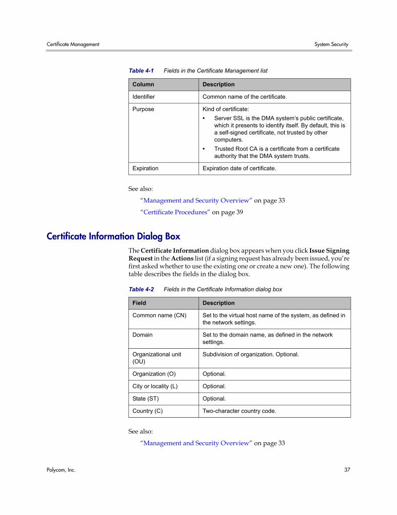
Certificate Management The following table describes the fields in the Certificate Management list.
Certificate Management System Security
Polycom, Inc. 37
See also:
“Management and Security Overview” on page 33
“Certificate Procedures” on page 39
Certificate Information Dialog Box The Certificate Information dialog box appears when you click Issue Signing Request in the Actions list (if a signing request has already been issued, you’re first asked whether to use the existing one or create a new one). The following table describes the fields in the dialog box.
See also:
“Management and Security Overview” on page 33
Table 4-1 Fields in the Certificate Management list
Column Description
Identifier Common name of the certificate.
Purpose Kind of certificate:
• Server SSL is the DMA system’s public certificate, which it presents to identify itself. By default, this is a self-signed certificate, not trusted by other computers.
• Trusted Root CA is a certificate from a certificate authority that the DMA system trusts.
Expiration Expiration date of certificate.
Table 4-2 Fields in the Certificate Information dialog box
Field Description
Common name (CN) Set to the virtual host name of the system, as defined in the network settings.
Domain Set to the domain name, as defined in the network settings.
Organizational unit (OU)
Subdivision of organization. Optional.
Organization (O) Optional.
City or locality (L) Optional.
State (ST) Optional.
Country (C) Two-character country code.
DMA Operations Guide Certificate Management
38 Polycom, Inc.
“Certificate Management” on page 36
“Certificate Procedures” on page 39
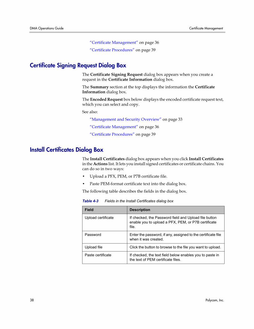
Certificate Signing Request Dialog Box The Certificate Signing Request dialog box appears when you create a request in the Certificate Information dialog box.
The Summary section at the top displays the information the Certificate Information dialog box.
The Encoded Request box below displays the encoded certificate request text, which you can select and copy.
See also:
“Management and Security Overview” on page 33
“Certificate Management” on page 36
“Certificate Procedures” on page 39
Install Certificates Dialog Box The Install Certificates dialog box appears when you click Install Certificates in the Actions list. It lets you install signed certificates or certificate chains. You can do so in two ways:
• Upload a PFX, PEM, or P7B certificate file.
• Paste PEM-format certificate text into the dialog box.
The following table describes the fields in the dialog box.
Table 4-3 Fields in the Install Certificates dialog box
Field Description
Upload certificate If checked, the Password field and Upload file button enable you to upload a PFX, PEM, or P7B certificate file.
Password Enter the password, if any, assigned to the certificate file when it was created.
Upload file Click the button to browse to the file you want to upload.
Paste certificate If checked, the text field below enables you to paste in the text of PEM certificate files.
Certificate Procedures System Security
Polycom, Inc. 39
See also:
“Management and Security Overview” on page 33
“Certificate Management” on page 36
“Certificate Procedures” on page 39
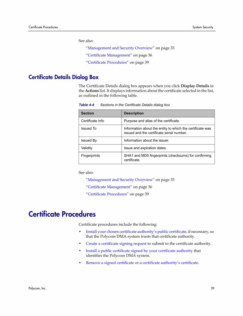
Certificate Details Dialog Box The Certificate Details dialog box appears when you click Display Details in the Actions list. It displays information about the certificate selected in the list, as outlined in the following table.
See also:
“Management and Security Overview” on page 33
“Certificate Management” on page 36
“Certificate Procedures” on page 39
Certificate Procedures Certificate procedures include the following:
• Install your chosen certificate authority’s public certificate, if necessary, so that the Polycom DMA system trusts that certificate authority.
• Create a certificate signing request to submit to the certificate authority.
• Install a public certificate signed by your certificate authority that identifies the Polycom DMA system.
• Remove a signed certificate or a certificate authority’s certificate.
Table 4-4 Sections in the Certificate Details dialog box
Section Description
Certificate Info Purpose and alias of the certificate.
Issued To Information about the entity to which the certificate was issued and the certificate serial number.
Issued By Information about the issuer.
Validity Issue and expiration dates.
Fingerprints SHA1 and MD5 fingerprints (checksums) for confirming certificate.
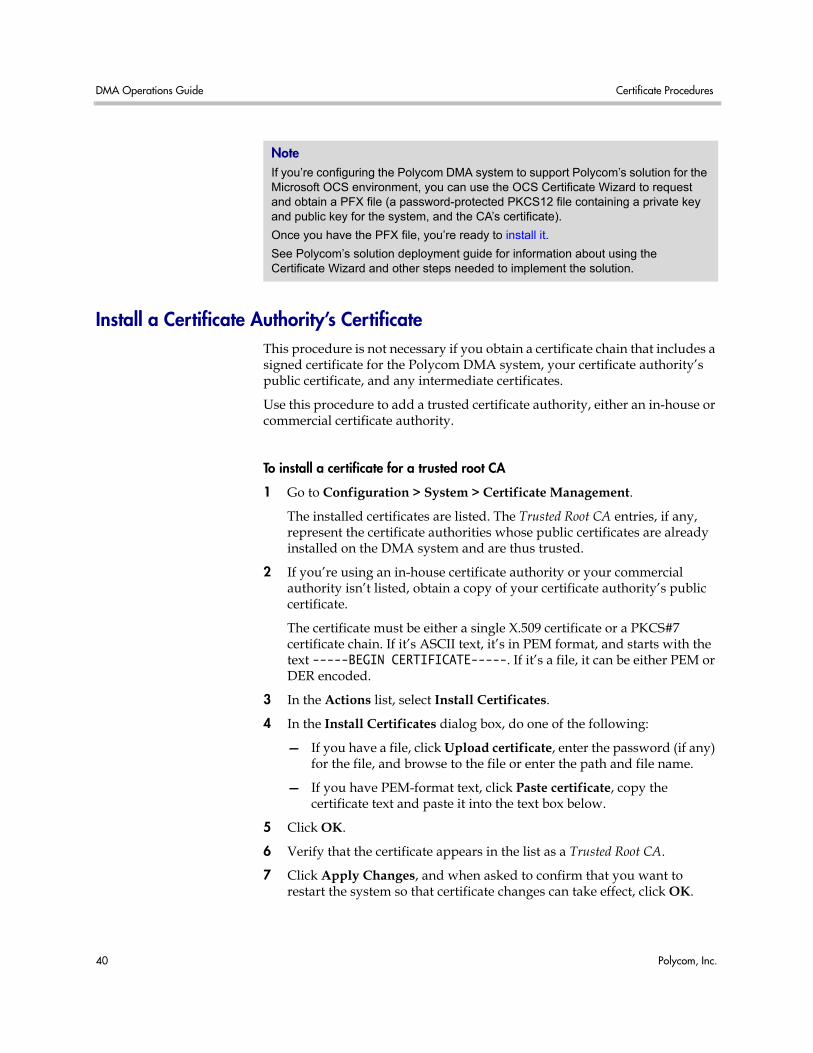
DMA Operations Guide Certificate Procedures
40 Polycom, Inc.
Install a Certificate Authority’s Certificate This procedure is not necessary if you obtain a certificate chain that includes a signed certificate for the Polycom DMA system, your certificate authority’s public certificate, and any intermediate certificates.
Use this procedure to add a trusted certificate authority, either an in-house or commercial certificate authority.
To install a certificate for a trusted root CA
1 Go to Configuration > System > Certificate Management.
The installed certificates are listed. The Trusted Root CA entries, if any, represent the certificate authorities whose public certificates are already installed on the DMA system and are thus trusted.
2 If you’re using an in-house certificate authority or your commercial authority isn’t listed, obtain a copy of your certificate authority’s public certificate.
The certificate must be either a single X.509 certificate or a PKCS#7 certificate chain. If it’s ASCII text, it’s in PEM format, and starts with the text -----BEGIN CERTIFICATE-----. If it’s a file, it can be either PEM or DER encoded.
3 In the Actions list, select Install Certificates.
4 In the Install Certificates dialog box, do one of the following:
— If you have a file, click Upload certificate, enter the password (if any) for the file, and browse to the file or enter the path and file name.
— If you have PEM-format text, click Paste certificate, copy the certificate text and paste it into the text box below.
5 Click OK.
6 Verify that the certificate appears in the list as a Trusted Root CA.
7 Click Apply Changes, and when asked to confirm that you want to restart the system so that certificate changes can take effect, click OK.
Note If you’re configuring the Polycom DMA system to support Polycom’s solution for the Microsoft OCS environment, you can use the OCS Certificate Wizard to request and obtain a PFX file (a password-protected PKCS12 file containing a private key and public key for the system, and the CA’s certificate).
Once you have the PFX file, you’re ready to install it.
See Polycom’s solution deployment guide for information about using the Certificate Wizard and other steps needed to implement the solution.
Certificate Procedures System Security
Polycom, Inc. 41
See also:
“Management and Security Overview” on page 33
“Certificate Management” on page 36
“Certificate Procedures” on page 39
Create a Certificate Signing Request in the DMA System The procedure below creates a certificate signing request (CSR) that you can submit to your chosen certificate authority.
To create a certificate signing request
1 Go to Configuration > System > Certificate Management.
By default, the system is configured to use a self-signed certificate.
2 To see details of the public certificate currently being used to identify the system to other computers:
a In the list, select the Server SSL certificate.
b In the Actions list, select Display Details.
The Certificate Details dialog box appears. If this is the default self-signed certificate, Organizational Unit is Default Certificate.
c To close the dialog box, click OK.
3 In the Actions list, select Issue Signing Request.
If you’ve created a signing request before, you’re asked if you want to use your existing certificate request or generate a new one. Elect to generate a new one.
4 In the Certificate Information dialog box, enter the identifying information for your Polycom DMA system (see “Certificate Information Dialog Box” on page 37) and click OK.
The Certificate Signing Request dialog box displays the encoded request (see “Certificate Signing Request Dialog Box” on page 38).
5 Copy the entire contents of the Encoded Request box (including the text -----BEGIN NEW CERTIFICATE REQUEST----- and -----END NEW CERTIFICATE REQUEST-----) and submit it to your certificate authority.
Depending on the certificate authority, your CSR may be submitted via email or by pasting into a web page.
6 Click OK to close the dialog box.
DMA Operations Guide Certificate Procedures
42 Polycom, Inc.
When your certificate authority has processed your request, it sends you a signed public certificate for your Polycom DMA system. Some certificate authorities also send intermediate certificates and/or root certificates. Depending on the certificate authority, these certificates may arrive as email text, email attachments, or be available on a secure web page.
The Polycom DMA system accepts PKCS#7 or PKCS#12 certificate chains or single certificates.
See also:
“Management and Security Overview” on page 33
“Certificate Management” on page 36
“Certificate Procedures” on page 39
Install a Certificate in the DMA System The procedure below installs the certificate or certificate chain provided by the certificate authority. It assumes that you’ve received the certificate or certificate chain in one of the following forms:
• A PFX, P7B, or single certificate file that you’ve saved on your computer.
• PEM-format encoded text that you received in an email or on a secure web page.
To install a signed certificate that identifies the Polycom DMA system
1 When you receive your certificate(s), return to Configuration > System > Certificate Management.
2 In the Actions list, select Install Certificates.
3 In the Install Certificates dialog box, do one of the following:
— If you have a PFX, P7B, or single certificate file, click Upload certificate, enter the password (if any) for the file, and browse to the file or enter the path and file name.
— If you have PEM-format text, click Paste certificate, copy the certificate text and paste it into the text box below. You can paste multiple PEM certificates one after the other.
4 Click OK.
5 To verify that the new signed certificate has replaced the default self-signed certificate:
a In the list of certificates, once again select the Server SSL certificate.
b In the Actions list, select Display Details.
The Certificate Details dialog box appears.
Certificate Procedures System Security
Polycom, Inc. 43
c Confirm from the information under Issued To and Issued By that the self-signed default certificate has been replaced by your signed public certificate from the certificate authority.
d To close the dialog box, click OK.
6 Click Apply Changes, and when asked to confirm that you want to restart the system so that certificate changes can take effect, click OK.
See also:
“Management and Security Overview” on page 33
“Certificate Management” on page 36
“Certificate Procedures” on page 39
Remove a Certificate from the DMA System There are two kinds of certificate removal:
• Removing the certificate of a Trusted Root CA so that the system no longer trusts certificates signed by that certificate authority.
• Removing the signed certificate currently in use as the Server SSL certificate so that the system reverts to using the default self-signed Server SSL certificate.
Removing a signed certificate also removes the certificate of the Trusted Root CA that signed it, along with any intermediate certificates provided by that certificate authority.
Both procedures are described below.
To remove a Trusted Root CA’s certificate
1 Go to Configuration > System > Certificate Management.
2 In the certificates list, select the certificate you want to delete.
3 In the Actions list, select Display Details and confirm that you’ve selected the correct certificate. Then click OK.
4 In the Actions list, select Delete Certificate.
5 In the Confirm Action dialog box, click Yes.
To remove a signed certificate and revert to the default self-signed certificate
1 Go to Configuration > System > Certificate Management.
2 In the Actions list, select Revert to Default Certificate.
3 In the Confirm Action dialog box, click Yes, and when asked to confirm that you want to restart the system so that certificate changes can take effect, click OK.
DMA Operations Guide Security Configuration
44 Polycom, Inc.
4 After the system restarts, log back in, return to Configuration > System > Certificate Management, and verify that the system has reverted to the default self-signed certificate:
a In the list of certificates, select the Server SSL certificate.
b In the Actions list, select Display Details.
The Certificate Details dialog box appears.
c Confirm from the information under Issued To and Issued By that the default self-signed certificate has replaced the CA-signed certificate.
d To close the dialog box, click OK.
5 Click Apply Changes, and when asked to confirm that you want to restart the system so that certificate changes can take effect, click OK.
See also:
“Management and Security Overview” on page 33
“Certificate Management” on page 36
“Certificate Procedures” on page 39
Security Configuration The Security Configuration page lets you switch between the maximum security mode and a custom security mode in which one or more insecure capabilities are allowed.
The following table describes the options in the Security Configuration page.
Table 4-5 Fields on the Security Configuration page
Field Description
Maximum security Recommended setting for normal operation.
Custom security Lets you enable one or more of the following unsecured methods of network access when necessary.
Allow Linux console access
Enables the Linux user root to log into the system using SSH. This direct Linux access isn’t needed for normal operation, routine maintenance, or even troubleshooting, all of which can be done through the administrative GUI.
In extreme circumstances, this option might enable expert Polycom Global Services.personnel to more fully understand the state of a troubled system or correct problems. Enable this option only when asked to do so by Polycom Global Services.
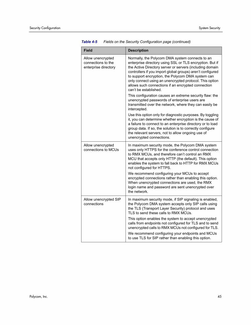
Security Configuration System Security
Polycom, Inc. 45
Allow unencrypted connections to the enterprise directory
Normally, the Polycom DMA system connects to an enterprise directory using SSL or TLS encryption. But if the Active Directory server or servers (including domain controllers if you import global groups) aren’t configured to support encryption, the Polycom DMA system can only connect using an unencrypted protocol. This option allows such connections if an encrypted connection can’t be established.
This configuration causes an extreme security flaw: the unencrypted passwords of enterprise users are transmitted over the network, where they can easily be intercepted.
Use this option only for diagnostic purposes. By toggling it, you can determine whether encryption is the cause of a failure to connect to an enterprise directory or to load group data. If so, the solution is to correctly configure the relevant servers, not to allow ongoing use of unencrypted connections.
Allow unencrypted connections to MCUs
In maximum security mode, the Polycom DMA system uses only HTTPS for the conference control connection to RMX MCUs, and therefore can’t control an RMX MCU that accepts only HTTP (the default). This option enables the system to fall back to HTTP for RMX MCUs not configured for HTTPS.
We recommend configuring your MCUs to accept encrypted connections rather than enabling this option. When unencrypted connections are used, the RMX login name and password are sent unencrypted over the network.
Allow unencrypted SIP connections
In maximum security mode, if SIP signaling is enabled, the Polycom DMA system accepts only SIP calls using the TLS (Transport Layer Security) protocol and uses TLS to send these calls to RMX MCUs.
This option enables the system to accept unencrypted calls from endpoints not configured for TLS and to send unencrypted calls to RMX MCUs not configured for TLS.
We recommend configuring your endpoints and MCUs to use TLS for SIP rather than enabling this option.
Table 4-5 Fields on the Security Configuration page (continued)
Field Description
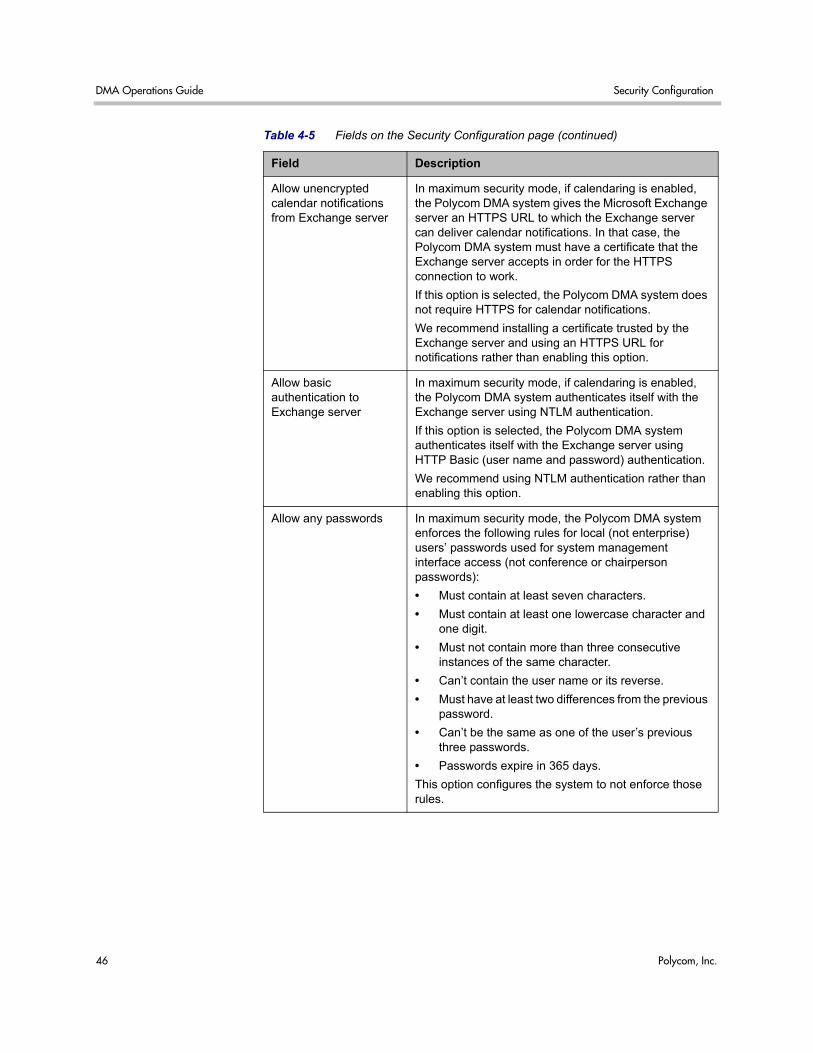
DMA Operations Guide Security Configuration
46 Polycom, Inc.
Allow unencrypted calendar notifications from Exchange server
In maximum security mode, if calendaring is enabled, the Polycom DMA system gives the Microsoft Exchange server an HTTPS URL to which the Exchange server can deliver calendar notifications. In that case, the Polycom DMA system must have a certificate that the Exchange server accepts in order for the HTTPS connection to work.
If this option is selected, the Polycom DMA system does not require HTTPS for calendar notifications.
We recommend installing a certificate trusted by the Exchange server and using an HTTPS URL for notifications rather than enabling this option.
Allow basic authentication to Exchange server
In maximum security mode, if calendaring is enabled, the Polycom DMA system authenticates itself with the Exchange server using NTLM authentication.
If this option is selected, the Polycom DMA system authenticates itself with the Exchange server using HTTP Basic (user name and password) authentication.
We recommend using NTLM authentication rather than enabling this option.
Allow any passwords In maximum security mode, the Polycom DMA system enforces the following rules for local (not enterprise) users’ passwords used for system management interface access (not conference or chairperson passwords):
• Must contain at least seven characters.
• Must contain at least one lowercase character and one digit.
• Must not contain more than three consecutive instances of the same character.
• Can’t contain the user name or its reverse.
• Must have at least two differences from the previous password.
• Can’t be the same as one of the user’s previous three passwords.
• Passwords expire in 365 days.
This option configures the system to not enforce those rules.
Table 4-5 Fields on the Security Configuration page (continued)
Field Description
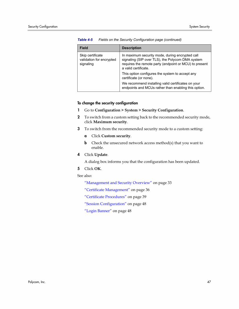
Security Configuration System Security
Polycom, Inc. 47
To change the security configuration
1 Go to Configuration > System > Security Configuration.
2 To switch from a custom setting back to the recommended security mode, click Maximum security.
3 To switch from the recommended security mode to a custom setting:
a Click Custom security.
b Check the unsecured network access method(s) that you want to enable.
4 Click Update.
A dialog box informs you that the configuration has been updated.
5 Click OK.
See also:
“Management and Security Overview” on page 33
“Certificate Management” on page 36
“Certificate Procedures” on page 39
“Session Configuration” on page 48
“Login Banner” on page 48
Skip certificate validation for encrypted signaling
In maximum security mode, during encrypted call signaling (SIP over TLS), the Polycom DMA system requires the remote party (endpoint or MCU) to present a valid certificate.
This option configures the system to accept any certificate (or none).
We recommend installing valid certificates on your endpoints and MCUs rather than enabling this option.
Table 4-5 Fields on the Security Configuration page (continued)
Field Description
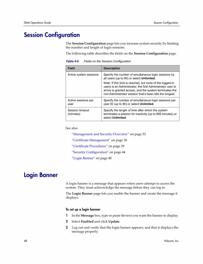
DMA Operations Guide Session Configuration
48 Polycom, Inc.
Session Configuration The Session Configuration page lets you increase system security by limiting the number and length of login sessions.
The following table describes the fields on the Session Configuration page.
See also:
“Management and Security Overview” on page 33
“Certificate Management” on page 36
“Certificate Procedures” on page 39
“Security Configuration” on page 44
“Login Banner” on page 48
Login Banner A login banner is a message that appears when users attempt to access the system. They must acknowledge the message before they can log in.
The Login Banner page lets you enable the banner and create the message it displays.
To set up a login banner
1 In the Message box, type or paste the text you want the banner to display.
2 Select Enabled and click Update.
3 Log out and verify that the login banner appears, and that it displays the message properly.
Table 4-6 Fields on the Session Configuration
Field Description
Active system sessions Specify the number of simultaneous login sessions by all users (up to 80) or select Unlimited.
Note: If this limit is reached, but none of the logged-in users is an Administrator, the first Administrator user to arrive is granted access, and the system terminates the non-Administrator session that’s been idle the longest.
Active sessions per user
Specify the number of simultaneous login sessions per user ID (up to 80) or select Unlimited.
Session timeout (minutes)
Specify the length of time after which the system terminates a session for inactivity (up to 999 minutes) or select Unlimited.
Login Banner System Security
Polycom, Inc. 49
See also:
“Management and Security Overview” on page 33
“Certificate Management” on page 36
“Certificate Procedures” on page 39
“Security Configuration” on page 44
“Session Configuration” on page 48

DMA Operations Guide Login Banner
50 Polycom, Inc.
Polycom, Inc. 51
5Device Management
This chapter describes the Polycom® Distributed Media Application™ (DMA™) 7000 system’s device management tools and tasks:
• MCUs
• MCU Zones
• MCU Zone Orders
MCUs The MCUs page shows the MCUs, or media servers, that the Polycom DMA system can use as conferencing resources. The following table describes the fields in the list.
Table 5-1 Information in the MCU list
Column Description
Connection and service status and capabilities:
Connected Disconnected
In service Out of service
Busied out Not licensed
Supports conference recording
Doesn’t support conference recording
Doesn’t support a signaling type supported
by the Polycom DMA system
Doesn’t support restricting ports (appears
only if restricted ports are specified in DMA)
Name The name of the MCU.
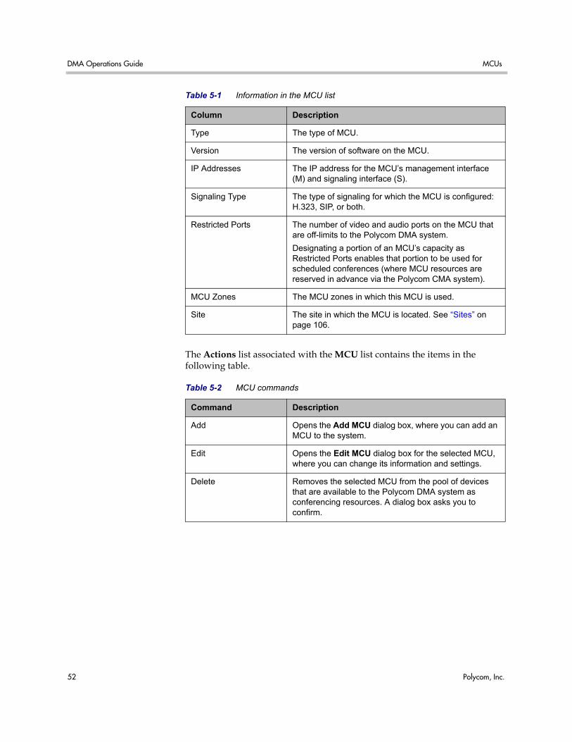
DMA Operations Guide MCUs
52 Polycom, Inc.
The Actions list associated with the MCU list contains the items in the following table.
Type The type of MCU.
Version The version of software on the MCU.
IP Addresses The IP address for the MCU’s management interface (M) and signaling interface (S).
Signaling Type The type of signaling for which the MCU is configured: H.323, SIP, or both.
Restricted Ports The number of video and audio ports on the MCU that are off-limits to the Polycom DMA system.
Designating a portion of an MCU’s capacity as Restricted Ports enables that portion to be used for scheduled conferences (where MCU resources are reserved in advance via the Polycom CMA system).
MCU Zones The MCU zones in which this MCU is used.
Site The site in which the MCU is located. See “Sites” on page 106.
Table 5-1 Information in the MCU list
Column Description
Table 5-2 MCU commands
Command Description
Add Opens the Add MCU dialog box, where you can add an MCU to the system.
Edit Opens the Edit MCU dialog box for the selected MCU, where you can change its information and settings.
Delete Removes the selected MCU from the pool of devices that are available to the Polycom DMA system as conferencing resources. A dialog box asks you to confirm.
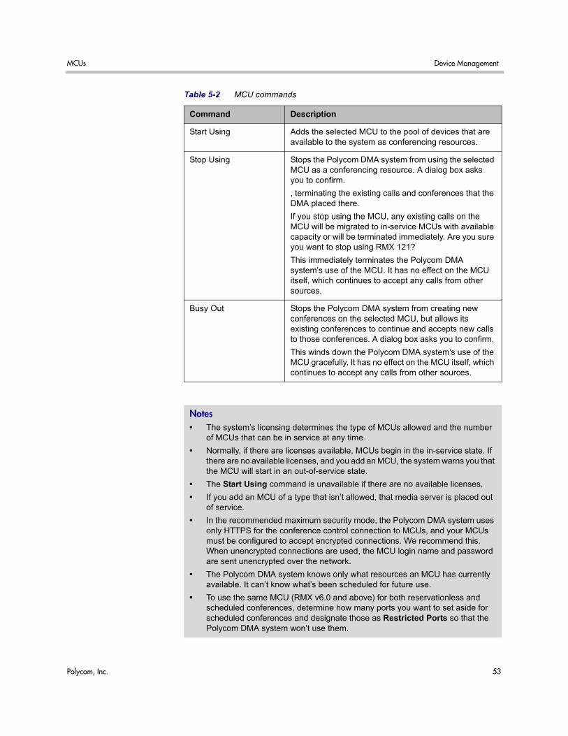
MCUs Device Management
Polycom, Inc. 53
Start Using Adds the selected MCU to the pool of devices that are available to the system as conferencing resources.
Stop Using Stops the Polycom DMA system from using the selected MCU as a conferencing resource. A dialog box asks you to confirm.
, terminating the existing calls and conferences that the DMA placed there.
If you stop using the MCU, any existing calls on the MCU will be migrated to in-service MCUs with available capacity or will be terminated immediately. Are you sure you want to stop using RMX 121?
This immediately terminates the Polycom DMA system’s use of the MCU. It has no effect on the MCU itself, which continues to accept any calls from other sources.
Busy Out Stops the Polycom DMA system from creating new conferences on the selected MCU, but allows its existing conferences to continue and accepts new calls to those conferences. A dialog box asks you to confirm.
This winds down the Polycom DMA system’s use of the MCU gracefully. It has no effect on the MCU itself, which continues to accept any calls from other sources.
Notes • The system’s licensing determines the type of MCUs allowed and the number
of MCUs that can be in service at any time.
• Normally, if there are licenses available, MCUs begin in the in-service state. If there are no available licenses, and you add an MCU, the system warns you that the MCU will start in an out-of-service state.
• The Start Using command is unavailable if there are no available licenses.
• If you add an MCU of a type that isn’t allowed, that media server is placed out of service.
• In the recommended maximum security mode, the Polycom DMA system uses only HTTPS for the conference control connection to MCUs, and your MCUs must be configured to accept encrypted connections. We recommend this. When unencrypted connections are used, the MCU login name and password are sent unencrypted over the network.
• The Polycom DMA system knows only what resources an MCU has currently available. It can’t know what’s been scheduled for future use.
• To use the same MCU (RMX v6.0 and above) for both reservationless and scheduled conferences, determine how many ports you want to set aside for scheduled conferences and designate those as Restricted Ports so that the Polycom DMA system won’t use them.
Table 5-2 MCU commands
Command Description
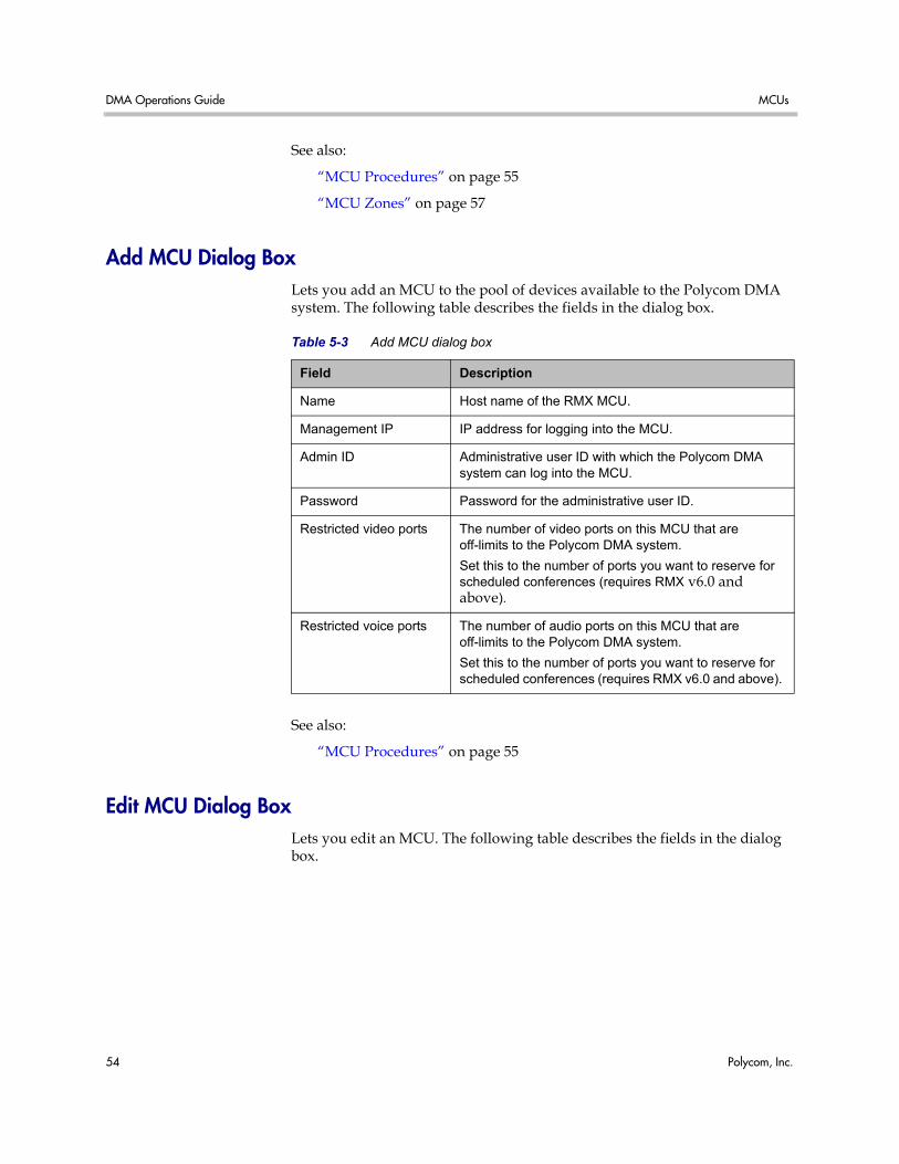
DMA Operations Guide MCUs
54 Polycom, Inc.
See also:
“MCU Procedures” on page 55
“MCU Zones” on page 57
Add MCU Dialog Box Lets you add an MCU to the pool of devices available to the Polycom DMA system. The following table describes the fields in the dialog box.
See also:
“MCU Procedures” on page 55
Edit MCU Dialog Box Lets you edit an MCU. The following table describes the fields in the dialog box.
Table 5-3 Add MCU dialog box
Field Description
Name Host name of the RMX MCU.
Management IP IP address for logging into the MCU.
Admin ID Administrative user ID with which the Polycom DMA system can log into the MCU.
Password Password for the administrative user ID.
Restricted video ports The number of video ports on this MCU that are off-limits to the Polycom DMA system.
Set this to the number of ports you want to reserve for scheduled conferences (requires RMX v6.0 and above).
Restricted voice ports The number of audio ports on this MCU that are off-limits to the Polycom DMA system.
Set this to the number of ports you want to reserve for scheduled conferences (requires RMX v6.0 and above).
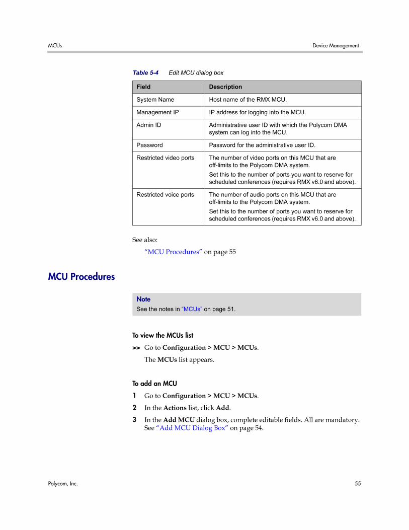
MCUs Device Management
Polycom, Inc. 55
See also:
“MCU Procedures” on page 55
MCU Procedures
To view the MCUs list
>> Go to Configuration > MCU > MCUs.
The MCUs list appears.
To add an MCU
1 Go to Configuration > MCU > MCUs.
2 In the Actions list, click Add.
3 In the Add MCU dialog box, complete editable fields. All are mandatory. See “Add MCU Dialog Box” on page 54.
Table 5-4 Edit MCU dialog box
Field Description
System Name Host name of the RMX MCU.
Management IP IP address for logging into the MCU.
Admin ID Administrative user ID with which the Polycom DMA system can log into the MCU.
Password Password for the administrative user ID.
Restricted video ports The number of video ports on this MCU that are off-limits to the Polycom DMA system.
Set this to the number of ports you want to reserve for scheduled conferences (requires RMX v6.0 and above).
Restricted voice ports The number of audio ports on this MCU that are off-limits to the Polycom DMA system.
Set this to the number of ports you want to reserve for scheduled conferences (requires RMX v6.0 and above).
Note See the notes in “MCUs” on page 51.
DMA Operations Guide MCUs
56 Polycom, Inc.
4 To make some of the MCU’s capacity off-limits to the Polycom DMA system, set Restricted video ports and Restricted audio ports to the values you want to set aside (requires v5.0 and above with MPM+).
Use these settings to divide the MCU’s resources between scheduled conferencing (Polycom CMA-controlled) and reservationless conferencing (Polycom DMA-controlled).
5 Click OK.
The new MCU appears in the MCUs list. If the system has a license available for the MCU, it’s placed into service. Otherwise, it remains out of service.
To edit an MCU
1 Go to Configuration > MCU > MCUs.
2 In the MCUs list, select the MCU of interest, and in the Actions list, click Edit.
3 In the Edit MCU dialog box, edit the fields as required. See “Edit MCU Dialog Box” on page 54.
4 To make more or fewer ports off-limits to the Polycom DMA system, change the Restricted video ports and Restricted audio ports values (requires v5.0 and above with MPM+).
5 Click OK.
The changes you made appear in the MCUs list.
To delete an MCU
1 Go to Configuration > MCU > MCUs.
2 In the MCUs list, select the MCU you want to remove from the Polycom DMA system’s pool of available conferencing resources.
3 In the Actions list, select Delete.
4 When asked to confirm that you want to delete the selected MCU, click Yes.
To terminate existing calls and conferences on an MCU and stop using it
1 Go to Configuration > MCU > MCUs.
2 In the MCUs list, select the MCU of interest.
3 In the Actions list, select Stop Using.
MCU Zones Device Management
Polycom, Inc. 57
4 When asked to confirm that you want to stop using the MCU, click Yes.
The Polycom DMA system immediately terminates all calls and conferences that it placed on that MCU.
This has no effect on the MCU itself, which continues to accept any calls to it from other sources.
To stop using an MCU, but allow existing calls and conferences to continue
1 Go to Configuration > MCU > MCUs.
2 In the MCUs list, select the MCU of interest.
3 In the Actions list, select Busy Out.
4 When asked to confirm that you want to busy out the MCU, click Yes.
The Polycom DMA system stops creating new conferences on that MCU, but it allows its existing conferences to continue and accepts new calls to those conferences.
This has no effect on the MCU itself, which continues to accept any calls to it from other sources.
To start using an MCU again
1 Go to Configuration > MCU > MCUs.
2 In the MCUs list, select the out-of-service MCU of interest.
3 In the Actions list, select Start Using.
MCU Zones The MCU Zones list shows the MCU zones, or logical groupings of media servers, that are defined in the Polycom DMA system. A zone may pool MCUs based on location, capability, or some other factor.
Enterprise groups can be associated with an MCU zone order, which specifies the order of preference in which MCU zones are used. This lets you, for instance, ensure that all users in a specific domain are preferentially routed to conferencing resources in their geographic location.
The following table describes the fields in the list.
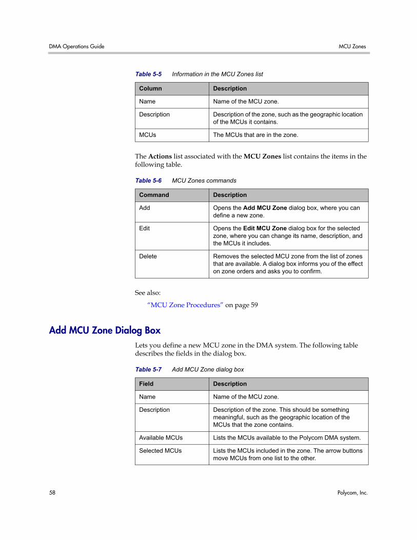
DMA Operations Guide MCU Zones
58 Polycom, Inc.
The Actions list associated with the MCU Zones list contains the items in the following table.
See also:
“MCU Zone Procedures” on page 59
Add MCU Zone Dialog Box Lets you define a new MCU zone in the DMA system. The following table describes the fields in the dialog box.
Table 5-5 Information in the MCU Zones list
Column Description
Name Name of the MCU zone.
Description Description of the zone, such as the geographic location of the MCUs it contains.
MCUs The MCUs that are in the zone.
Table 5-6 MCU Zones commands
Command Description
Add Opens the Add MCU Zone dialog box, where you can define a new zone.
Edit Opens the Edit MCU Zone dialog box for the selected zone, where you can change its name, description, and the MCUs it includes.
Delete Removes the selected MCU zone from the list of zones that are available. A dialog box informs you of the effect on zone orders and asks you to confirm.
Table 5-7 Add MCU Zone dialog box
Field Description
Name Name of the MCU zone.
Description Description of the zone. This should be something meaningful, such as the geographic location of the MCUs that the zone contains.
Available MCUs Lists the MCUs available to the Polycom DMA system.
Selected MCUs Lists the MCUs included in the zone. The arrow buttons move MCUs from one list to the other.
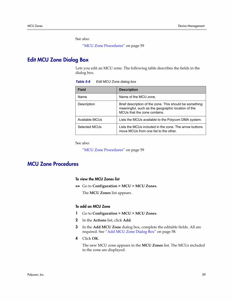
MCU Zones Device Management
Polycom, Inc. 59
See also:
“MCU Zone Procedures” on page 59
Edit MCU Zone Dialog Box Lets you edit an MCU zone. The following table describes the fields in the dialog box.
See also:
“MCU Zone Procedures” on page 59
MCU Zone Procedures
To view the MCU Zones list
>> Go to Configuration > MCU > MCU Zones.
The MCU Zones list appears.
To add an MCU Zone
1 Go to Configuration > MCU > MCU Zones.
2 In the Actions list, click Add.
3 In the Add MCU Zone dialog box, complete the editable fields. All are required. See “Add MCU Zone Dialog Box” on page 58.
4 Click OK.
The new MCU zone appears in the MCU Zones list. The MCUs included in the zone are displayed.
Table 5-8 Edit MCU Zone dialog box
Field Description
Name Name of the MCU zone.
Description Brief description of the zone. This should be something meaningful, such as the geographic location of the MCUs that the zone contains.
Available MCUs Lists the MCUs available to the Polycom DMA system.
Selected MCUs Lists the MCUs included in the zone. The arrow buttons move MCUs from one list to the other.
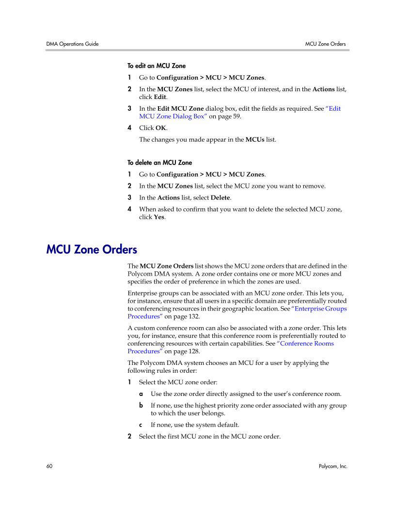
DMA Operations Guide MCU Zone Orders
60 Polycom, Inc.
To edit an MCU Zone
1 Go to Configuration > MCU > MCU Zones.
2 In the MCU Zones list, select the MCU of interest, and in the Actions list, click Edit.
3 In the Edit MCU Zone dialog box, edit the fields as required. See “Edit MCU Zone Dialog Box” on page 59.
4 Click OK.
The changes you made appear in the MCUs list.
To delete an MCU Zone
1 Go to Configuration > MCU > MCU Zones.
2 In the MCU Zones list, select the MCU zone you want to remove.
3 In the Actions list, select Delete.
4 When asked to confirm that you want to delete the selected MCU zone, click Yes.
MCU Zone Orders The MCU Zone Orders list shows the MCU zone orders that are defined in the Polycom DMA system. A zone order contains one or more MCU zones and specifies the order of preference in which the zones are used.
Enterprise groups can be associated with an MCU zone order. This lets you, for instance, ensure that all users in a specific domain are preferentially routed to conferencing resources in their geographic location. See “Enterprise Groups Procedures” on page 132.
A custom conference room can also be associated with a zone order. This lets you, for instance, ensure that this conference room is preferentially routed to conferencing resources with certain capabilities. See “Conference Rooms Procedures” on page 128.
The Polycom DMA system chooses an MCU for a user by applying the following rules in order:
1 Select the MCU zone order:
a Use the zone order directly assigned to the user’s conference room.
b If none, use the highest priority zone order associated with any group to which the user belongs.
c If none, use the system default.
2 Select the first MCU zone in the MCU zone order.
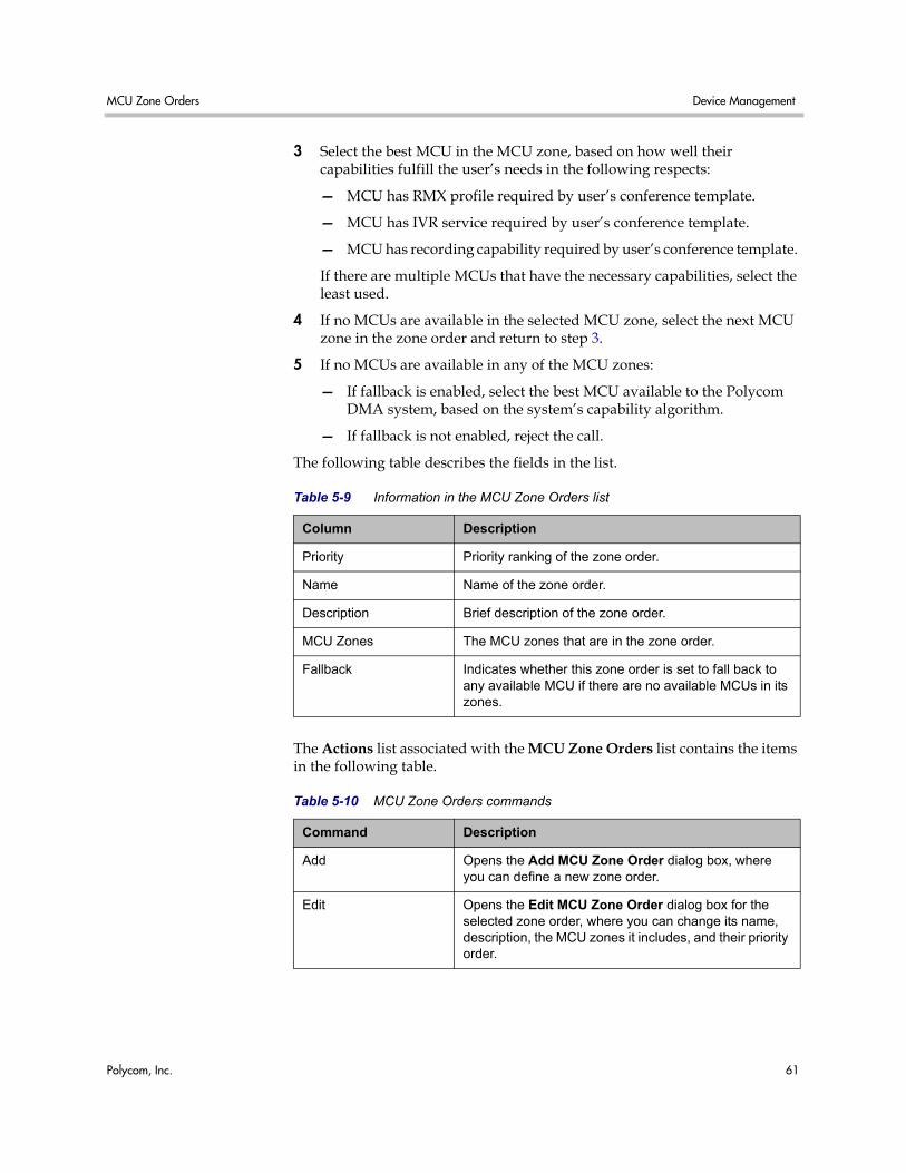
MCU Zone Orders Device Management
Polycom, Inc. 61
3 Select the best MCU in the MCU zone, based on how well their capabilities fulfill the user’s needs in the following respects:
— MCU has RMX profile required by user’s conference template.
— MCU has IVR service required by user’s conference template.
— MCU has recording capability required by user’s conference template.
If there are multiple MCUs that have the necessary capabilities, select the least used.
4 If no MCUs are available in the selected MCU zone, select the next MCU zone in the zone order and return to step 3.
5 If no MCUs are available in any of the MCU zones:
— If fallback is enabled, select the best MCU available to the Polycom DMA system, based on the system’s capability algorithm.
— If fallback is not enabled, reject the call.
The following table describes the fields in the list.
The Actions list associated with the MCU Zone Orders list contains the items in the following table.
Table 5-9 Information in the MCU Zone Orders list
Column Description
Priority Priority ranking of the zone order.
Name Name of the zone order.
Description Brief description of the zone order.
MCU Zones The MCU zones that are in the zone order.
Fallback Indicates whether this zone order is set to fall back to any available MCU if there are no available MCUs in its zones.
Table 5-10 MCU Zone Orders commands
Command Description
Add Opens the Add MCU Zone Order dialog box, where you can define a new zone order.
Edit Opens the Edit MCU Zone Order dialog box for the selected zone order, where you can change its name, description, the MCU zones it includes, and their priority order.
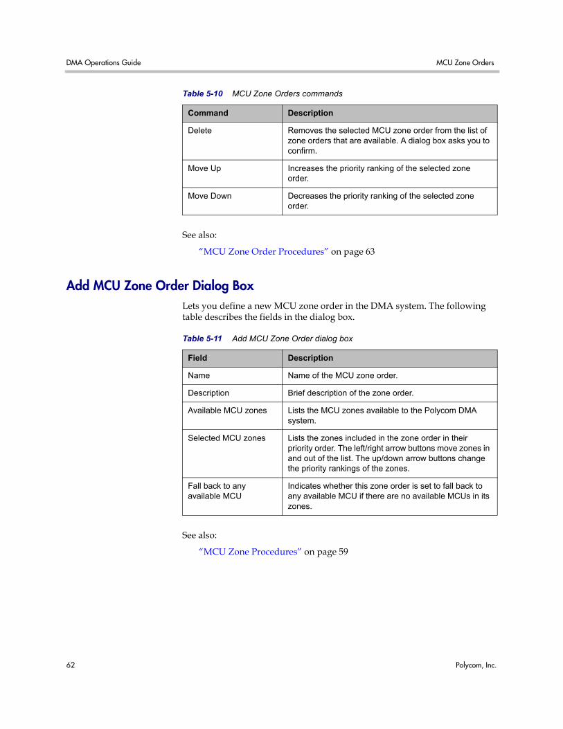
DMA Operations Guide MCU Zone Orders
62 Polycom, Inc.
See also:
“MCU Zone Order Procedures” on page 63
Add MCU Zone Order Dialog Box Lets you define a new MCU zone order in the DMA system. The following table describes the fields in the dialog box.
See also:
“MCU Zone Procedures” on page 59
Delete Removes the selected MCU zone order from the list of zone orders that are available. A dialog box asks you to confirm.
Move Up Increases the priority ranking of the selected zone order.
Move Down Decreases the priority ranking of the selected zone order.
Table 5-10 MCU Zone Orders commands
Command Description
Table 5-11 Add MCU Zone Order dialog box
Field Description
Name Name of the MCU zone order.
Description Brief description of the zone order.
Available MCU zones Lists the MCU zones available to the Polycom DMA system.
Selected MCU zones Lists the zones included in the zone order in their priority order. The left/right arrow buttons move zones in and out of the list. The up/down arrow buttons change the priority rankings of the zones.
Fall back to any available MCU
Indicates whether this zone order is set to fall back to any available MCU if there are no available MCUs in its zones.
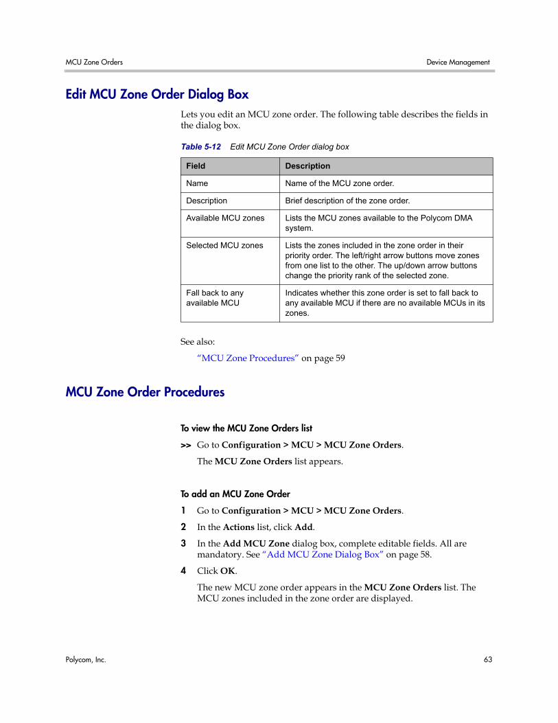
MCU Zone Orders Device Management
Polycom, Inc. 63
Edit MCU Zone Order Dialog Box Lets you edit an MCU zone order. The following table describes the fields in the dialog box.
See also:
“MCU Zone Procedures” on page 59
MCU Zone Order Procedures
To view the MCU Zone Orders list
>> Go to Configuration > MCU > MCU Zone Orders.
The MCU Zone Orders list appears.
To add an MCU Zone Order
1 Go to Configuration > MCU > MCU Zone Orders.
2 In the Actions list, click Add.
3 In the Add MCU Zone dialog box, complete editable fields. All are mandatory. See “Add MCU Zone Dialog Box” on page 58.
4 Click OK.
The new MCU zone order appears in the MCU Zone Orders list. The MCU zones included in the zone order are displayed.
Table 5-12 Edit MCU Zone Order dialog box
Field Description
Name Name of the MCU zone order.
Description Brief description of the zone order.
Available MCU zones Lists the MCU zones available to the Polycom DMA system.
Selected MCU zones Lists the zones included in the zone order in their priority order. The left/right arrow buttons move zones from one list to the other. The up/down arrow buttons change the priority rank of the selected zone.
Fall back to any available MCU
Indicates whether this zone order is set to fall back to any available MCU if there are no available MCUs in its zones.
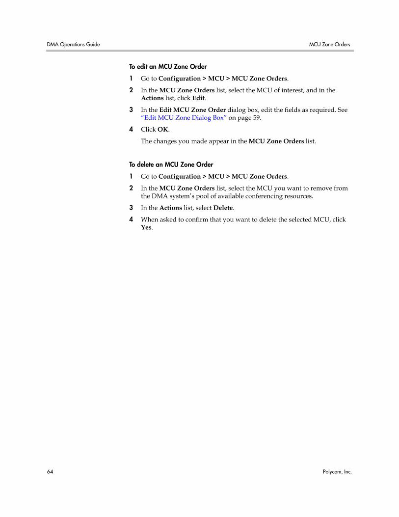
DMA Operations Guide MCU Zone Orders
64 Polycom, Inc.
To edit an MCU Zone Order
1 Go to Configuration > MCU > MCU Zone Orders.
2 In the MCU Zone Orders list, select the MCU of interest, and in the Actions list, click Edit.
3 In the Edit MCU Zone Order dialog box, edit the fields as required. See “Edit MCU Zone Dialog Box” on page 59.
4 Click OK.
The changes you made appear in the MCU Zone Orders list.
To delete an MCU Zone Order
1 Go to Configuration > MCU > MCU Zone Orders.
2 In the MCU Zone Orders list, select the MCU you want to remove from the DMA system’s pool of available conferencing resources.
3 In the Actions list, select Delete.
4 When asked to confirm that you want to delete the selected MCU, click Yes.
Polycom, Inc. 65
6Conference Setup
This chapter describes the following Polycom® Distributed Media Application™ (DMA™) 7000 system configuration topics related to conference setup:
• Conference Templates
• Conference Settings
• Calendaring Service
Conference Templates Conference templates are used to create users’ conference rooms, which define a user’s conference experience. A conference template specifies a set of conference properties, such as the line (bit) rate and video display mode.
Two Types of Templates You can create a conference template in two ways:
• Specify the individual conference properties directly in the Polycom DMA system, creating a “standalone” template independent of the profiles available on the system’s RMX MCUs.
• Link the template to an RMX profile that exists on some or all of the MCUs.
Standalone Templates Standalone templates defined in the Polycom DMA system free you from having to ensure that the exact same RMX profiles exist on all the MCUs. You specify the desired conference properties directly in the template.
When it uses a standalone template for a conference, the system sends the specific properties to the MCU instead of pointing to one of its profiles.
DMA Operations Guide Conference Templates
66 Polycom, Inc.
When using a template not linked to an RMX profile, the system doesn’t use the template’s properties to limit its choice of MCU. Unsupported properties are ignored or degrade gracefully if necessary. For instance:
• If a conference set to a 4096 kbps line rate is forced to land on an MCU that doesn’t support that value, the line rate falls back to 1920 kbps.
• If a conference with encryption enabled is forced to land on an MCU that doesn’t support encryption, that property is ignored.
To preferentially route conferences to certain MCUs, use MCU zone orders. See “MCU Zones” on page 57 and “MCU Zone Orders” on page 60.
Templates Linked to RMX Profiles Linking a template to an RMX profile lets you access profile properties that aren’t currently available in a standalone template.
When you link a template to a profile, it’s up to you to ensure that the profile exists on the MCUs you want to use with that template and that its settings are the same on all of them.
When it uses a profile-based template, the system tries to find an MCU that has that profile (but it does so within the MCU zone order rules; see “MCU Zones” on page 57 and “MCU Zone Orders” on page 60).
If it can’t find an MCU with that profile, it falls back to the system’s default conference template (see “Conference Settings” on page 82). If that template is also linked to a profile that none of the available MCUs have, the system falls back to its built-in conference properties settings.
See also:
“Conference Templates Procedures” on page 80
“Template Priority” on page 67
“Conference Templates List” on page 68
“Add Conference Template Dialog Box” on page 69
“Edit Conference Template Dialog Box” on page 74
“Conference Settings” on page 82
Note You can also use a template linked to an RMX profile to preferentially route conferences using that template to MCUs that have the profile. But we recommend that you create MCU zones and zone orders for this purpose. You can assign MCU zone orders to enterprise groups and to custom conference rooms. See “MCU Zones” on page 57 and “MCU Zone Orders” on page 60.
Conference Templates Conference Setup
Polycom, Inc. 67
Template Priority A user (local or enterprise) has one or more conference rooms, and each room may or may not have a specifically assigned template (typically, however, conference rooms use the system’s default template, as specified on the Conference Settings page).
An enterprise user can be associated with multiple enterprise groups, and each group may or may not have a specifically assigned template.
You can rank the conference templates by priority, so that the system knows which template to use when the user is associated with more than one.
When someone dials into a conference room, the system uses these rules (in order of importance) to determine which template to use for the conference:
1 If the conference room has a specifically assigned template (not the system default) associated with it, use that template.
2 If the user associated with the conference room belongs to one or more enterprise groups that have specifically assigned templates, use the template with the highest priority.
3 Otherwise, use the system default conference template.
See also:
“Conference Templates Procedures” on page 80
“Add Conference Template Dialog Box” on page 69
“Edit Conference Template Dialog Box” on page 74
“Conference Settings” on page 82
About Conference IVR Services One of the conference properties you can optionally specify in a template is the conference IVR service that the MCU should use. For most purposes, you shouldn’t do so. RMX MCUs have two defaults, one for conferences with passwords and one for conferences without passwords, and automatically use the right one for each conference.
If you do choose to override the default and specify an IVR service, it’s up to you to make sure that the IVR service you select is appropriate for the users whose conferences will use this template, and that it’s available on the MCUs on which those conference may take place. See your Polycom RMX documentation for information about conference IVR services.
On the Conference IVR tab of the Add Conference Template and Edit Conference Template dialog boxes, the list contains the names of all the conference IVR services available on the currently connected MCUs. Each entry also shows how many of the MCUs have that service (for instance, 2 of 3).
DMA Operations Guide Conference Templates
68 Polycom, Inc.
If a template specifies a conference IVR service, the system will put conferences using that template on the least used RMX that has that conference IVR service. If there are none, it falls back to the default conference IVR service.
About Cascading One of the conference features you can optionally enable in a template is cascading, which makes it possible for a conference to span MCUs. Cascading a conference across multiple MCUs can conserve bandwidth and is especially useful when using WAN links. Participants can connect to MCUs that are geographically near them, reducing network traffic between sites to a single link to each MCU.
Cascading does, however, impact the quality of the conference experience.
If you have a Polycom CMA 5000 system in your network, you can enable cascaded conferences with these steps:
1 On the Polycom CMA system, create site topology data defining the sites, site links, and MPLS clouds in your network, and the subnets in each site.
2 On the Polycom DMA system, integrate with the CMA system to obtain its site topology data. See “CMA Integration” on page 24.
3 On the Polycom DMA system, enable cascading in some or all of your conference templates.
If you don’t have a Polycom CMA 5000 system, you must define your site topology in the Polycom DMA system instead of importing it. See “Site Topology Configuration” on page 105.
For a conference with cascading enabled, the Polycom DMA system uses the site topology information to route calls to the nearest eligible MCU (based on zones and zone orders) that has available capacity. If that MCU is new to the conference, theDMA system creates the cascade link to the MCU initially chosen to host the conference.
Cascading always uses a hub-and-spoke configuration. The MCU chosen for the first call to a conference becomes the hub. Each new MCU is connected directly to that hub MCU. Cascade MCUs can never be more than one link away from the hub.
Note RMX MCUs support cascade links only in H.323. The Polycom DMA system must be configured to support H.323 signaling in order to enable cascading. For conferences with cascading enabled, the system selects only MCUs that have H.323 signaling enabled.
Conference Templates Conference Setup
Polycom, Inc. 69
Conference Templates List The following table describes the fields in the Conference Templates list.
The Polycom DMA system comes with a Factory Template that has a default set of conference parameters. You can edit that template and create additional templates.
See also:
“Conference Templates Procedures” on page 80
“Add Conference Template Dialog Box” on page 69
“Edit Conference Template Dialog Box” on page 74
Add Conference Template Dialog Box Lets you add a conference template. The following table describes the fields in the dialog box.
Table 6-1 Information in the Conference Templates list
Column Description
Priority The priority ranking of the template.
Name The name of the template.
Description A description of the template.
Table 6-2 Add Conference Template dialog box
Field Description
General Info
Name A meaningful name for the template (up to 50 characters).
Description A brief description (ASCII only) of the conference template (up to 50 characters).
Use existing profile Links this template to the RMX profile selected in the list below.
For most purposes, we recommend leaving this box unchecked and specifying conference properties directly. See “Conference Templates” on page 65.
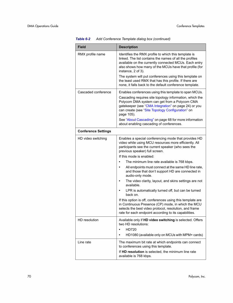
DMA Operations Guide Conference Templates
70 Polycom, Inc.
RMX profile name Identifies the RMX profile to which this template is linked. The list contains the names of all the profiles available on the currently connected MCUs. Each entry also shows how many of the MCUs have that profile (for instance, 2 of 3).
The system will put conferences using this template on the least used RMX that has this profile. If there are none, it falls back to the default conference template.
Cascaded conference Enables conferences using this template to span MCUs.
Cascading requires site topology information, which the Polycom DMA system can get from a Polycom CMA gatekeeper (see “CMA Integration” on page 24) or you can create (see “Site Topology Configuration” on page 105).
See “About Cascading” on page 68 for more information about enabling cascading of conferences.
Conference Settings
HD video switching Enables a special conferencing mode that provides HD video while using MCU resources more efficiently. All participants see the current speaker (who sees the previous speaker) full screen.
If this mode is enabled:
• The minimum line rate available is 768 kbps.
• All endpoints must connect at the same HD line rate, and those that don’t support HD are connected in audio-only mode.
• The video clarity, layout, and skins settings are not available.
• LPR is automatically turned off, but can be turned back on.
If this option is off, conferences using this template are in Continuous Presence (CP) mode, in which the MCU selects the best video protocol, resolution, and frame rate for each endpoint according to its capabilities.
HD resolution Available only if HD video switching is selected. Offers two HD resolutions:
• HD720
• HD1080 (available only on MCUs with MPM+ cards)
Line rate The maximum bit rate at which endpoints can connect to conferences using this template.
If HD resolution is selected, the minimum line rate available is 768 kbps.
Table 6-2 Add Conference Template dialog box (continued)
Field Description
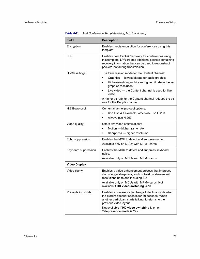
Conference Templates Conference Setup
Polycom, Inc. 71
Encryption Enables media encryption for conferences using this template.
LPR Enables Lost Packet Recovery for conferences using this template. LPR creates additional packets containing recovery information that can be used to reconstruct packets lost during transmission.
H.239 settings The transmission mode for the Content channel:
• Graphics — lowest bit rate for basic graphics
• High-resolution graphics — higher bit rate for better graphics resolution
• Live video — the Content channel is used for live video
A higher bit rate for the Content channel reduces the bit rate for the People channel.
H.239 protocol Content channel protocol options:
• Use H.264 if available, otherwise use H.263.
• Always use H.263.
Video quality Offers two video optimizations:
• Motion — higher frame rate
• Sharpness — higher resolution
Echo suppression Enables the MCU to detect and suppress echo.
Available only on MCUs with MPM+ cards.
Keyboard suppression Enables the MCU to detect and suppress keyboard noise.
Available only on MCUs with MPM+ cards.
Video Display
Video clarity Enables a video enhancement process that improves clarity, edge sharpness, and contrast on streams with resolutions up to and including SD.
Available only on MCUs with MPM+ cards. Not available if HD video switching is on.
Presentation mode Enables a conference to change to lecture mode when the current speaker speaks for 30 seconds. When another participant starts talking, it returns to the previous video layout.
Not available if HD video switching is on or Telepresence mode is Yes.
Table 6-2 Add Conference Template dialog box (continued)
Field Description
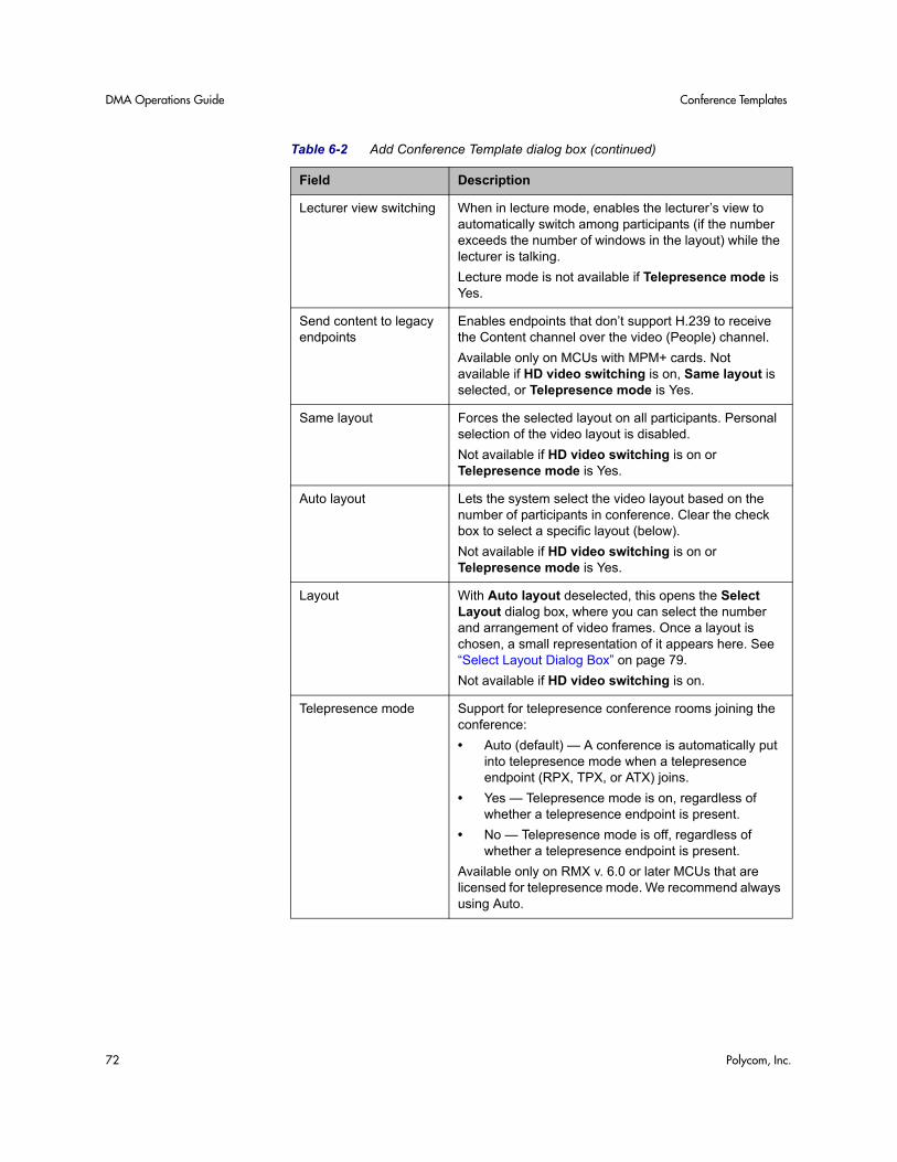
DMA Operations Guide Conference Templates
72 Polycom, Inc.
Lecturer view switching When in lecture mode, enables the lecturer’s view to automatically switch among participants (if the number exceeds the number of windows in the layout) while the lecturer is talking.
Lecture mode is not available if Telepresence mode is Yes.
Send content to legacy endpoints
Enables endpoints that don’t support H.239 to receive the Content channel over the video (People) channel.
Available only on MCUs with MPM+ cards. Not available if HD video switching is on, Same layout is selected, or Telepresence mode is Yes.
Same layout Forces the selected layout on all participants. Personal selection of the video layout is disabled.
Not available if HD video switching is on or Telepresence mode is Yes.
Auto layout Lets the system select the video layout based on the number of participants in conference. Clear the check box to select a specific layout (below).
Not available if HD video switching is on or Telepresence mode is Yes.
Layout With Auto layout deselected, this opens the Select Layout dialog box, where you can select the number and arrangement of video frames. Once a layout is chosen, a small representation of it appears here. See “Select Layout Dialog Box” on page 79.
Not available if HD video switching is on.
Telepresence mode Support for telepresence conference rooms joining the conference:
• Auto (default) — A conference is automatically put into telepresence mode when a telepresence endpoint (RPX, TPX, or ATX) joins.
• Yes — Telepresence mode is on, regardless of whether a telepresence endpoint is present.
• No — Telepresence mode is off, regardless of whether a telepresence endpoint is present.
Available only on RMX v. 6.0 or later MCUs that are licensed for telepresence mode. We recommend always using Auto.
Table 6-2 Add Conference Template dialog box (continued)
Field Description
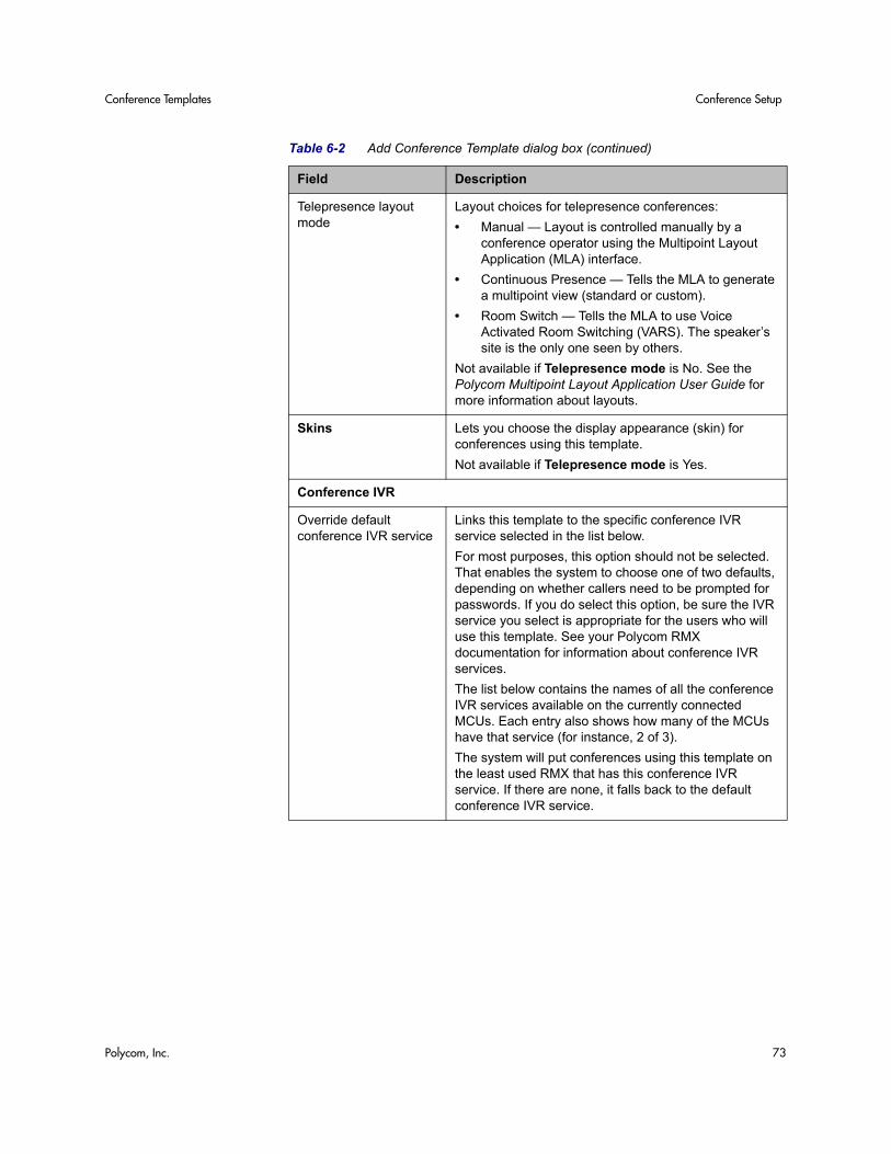
Conference Templates Conference Setup
Polycom, Inc. 73
Telepresence layout mode
Layout choices for telepresence conferences:
• Manual — Layout is controlled manually by a conference operator using the Multipoint Layout Application (MLA) interface.
• Continuous Presence — Tells the MLA to generate a multipoint view (standard or custom).
• Room Switch — Tells the MLA to use Voice Activated Room Switching (VARS). The speaker’s site is the only one seen by others.
Not available if Telepresence mode is No. See the Polycom Multipoint Layout Application User Guide for more information about layouts.
Skins Lets you choose the display appearance (skin) for conferences using this template.
Not available if Telepresence mode is Yes.
Conference IVR
Override default conference IVR service
Links this template to the specific conference IVR service selected in the list below.
For most purposes, this option should not be selected. That enables the system to choose one of two defaults, depending on whether callers need to be prompted for passwords. If you do select this option, be sure the IVR service you select is appropriate for the users who will use this template. See your Polycom RMX documentation for information about conference IVR services.
The list below contains the names of all the conference IVR services available on the currently connected MCUs. Each entry also shows how many of the MCUs have that service (for instance, 2 of 3).
The system will put conferences using this template on the least used RMX that has this conference IVR service. If there are none, it falls back to the default conference IVR service.
Table 6-2 Add Conference Template dialog box (continued)
Field Description
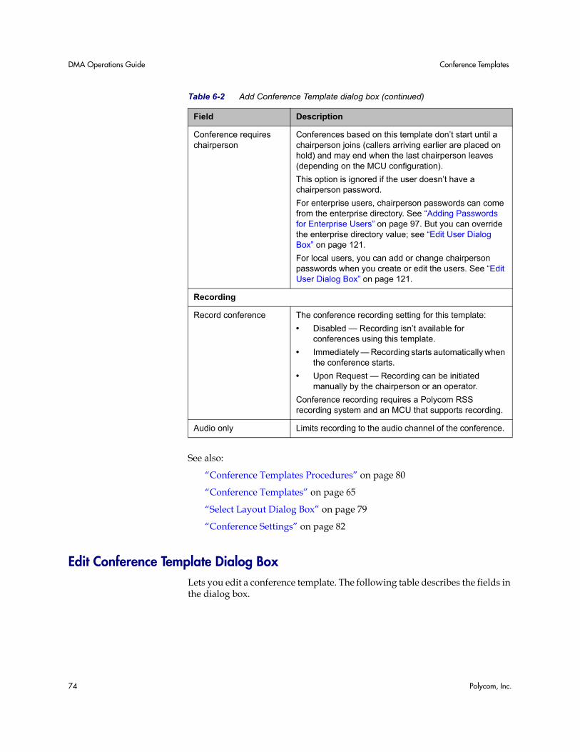
DMA Operations Guide Conference Templates
74 Polycom, Inc.
See also:
“Conference Templates Procedures” on page 80
“Conference Templates” on page 65
“Select Layout Dialog Box” on page 79
“Conference Settings” on page 82
Edit Conference Template Dialog Box Lets you edit a conference template. The following table describes the fields in the dialog box.
Conference requires chairperson
Conferences based on this template don’t start until a chairperson joins (callers arriving earlier are placed on hold) and may end when the last chairperson leaves (depending on the MCU configuration).
This option is ignored if the user doesn’t have a chairperson password.
For enterprise users, chairperson passwords can come from the enterprise directory. See “Adding Passwords for Enterprise Users” on page 97. But you can override the enterprise directory value; see “Edit User Dialog Box” on page 121.
For local users, you can add or change chairperson passwords when you create or edit the users. See “Edit User Dialog Box” on page 121.
Recording
Record conference The conference recording setting for this template:
• Disabled — Recording isn’t available for conferences using this template.
• Immediately — Recording starts automatically when the conference starts.
• Upon Request — Recording can be initiated manually by the chairperson or an operator.
Conference recording requires a Polycom RSS recording system and an MCU that supports recording.
Audio only Limits recording to the audio channel of the conference.
Table 6-2 Add Conference Template dialog box (continued)
Field Description
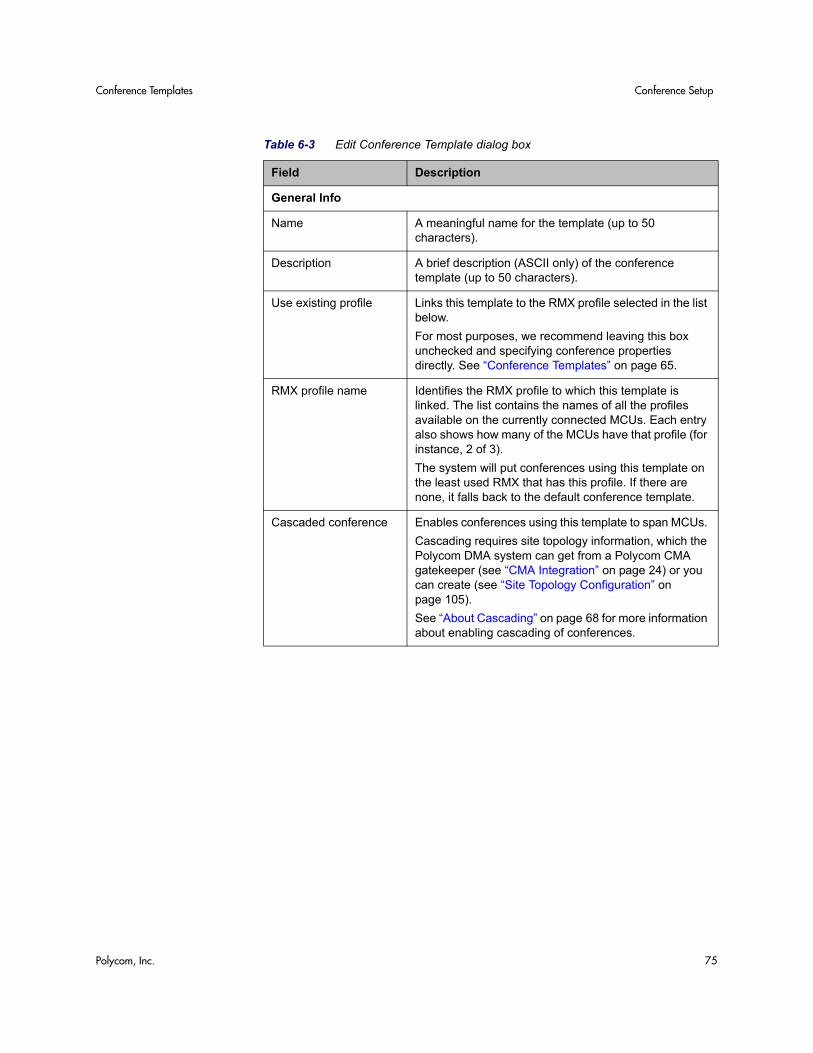
Conference Templates Conference Setup
Polycom, Inc. 75
Table 6-3 Edit Conference Template dialog box
Field Description
General Info
Name A meaningful name for the template (up to 50 characters).
Description A brief description (ASCII only) of the conference template (up to 50 characters).
Use existing profile Links this template to the RMX profile selected in the list below.
For most purposes, we recommend leaving this box unchecked and specifying conference properties directly. See “Conference Templates” on page 65.
RMX profile name Identifies the RMX profile to which this template is linked. The list contains the names of all the profiles available on the currently connected MCUs. Each entry also shows how many of the MCUs have that profile (for instance, 2 of 3).
The system will put conferences using this template on the least used RMX that has this profile. If there are none, it falls back to the default conference template.
Cascaded conference Enables conferences using this template to span MCUs.
Cascading requires site topology information, which the Polycom DMA system can get from a Polycom CMA gatekeeper (see “CMA Integration” on page 24) or you can create (see “Site Topology Configuration” on page 105).
See “About Cascading” on page 68 for more information about enabling cascading of conferences.
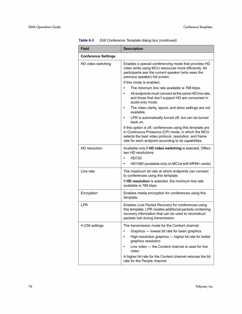
DMA Operations Guide Conference Templates
76 Polycom, Inc.
Conference Settings
HD video switching Enables a special conferencing mode that provides HD video while using MCU resources more efficiently. All participants see the current speaker (who sees the previous speaker) full screen.
If this mode is enabled:
• The minimum line rate available is 768 kbps.
• All endpoints must connect at the same HD line rate, and those that don’t support HD are connected in audio-only mode.
• The video clarity, layout, and skins settings are not available.
• LPR is automatically turned off, but can be turned back on.
If this option is off, conferences using this template are in Continuous Presence (CP) mode, in which the MCU selects the best video protocol, resolution, and frame rate for each endpoint according to its capabilities.
HD resolution Available only if HD video switching is selected. Offers two HD resolutions:
• HD720
• HD1080 (available only on MCUs with MPM+ cards)
Line rate The maximum bit rate at which endpoints can connect to conferences using this template.
If HD resolution is selected, the minimum line rate available is 768 kbps.
Encryption Enables media encryption for conferences using this template.
LPR Enables Lost Packet Recovery for conferences using this template. LPR creates additional packets containing recovery information that can be used to reconstruct packets lost during transmission.
H.239 settings The transmission mode for the Content channel:
• Graphics — lowest bit rate for basic graphics
• High-resolution graphics — higher bit rate for better graphics resolution
• Live video — the Content channel is used for live video
A higher bit rate for the Content channel reduces the bit rate for the People channel.
Table 6-3 Edit Conference Template dialog box (continued)
Field Description
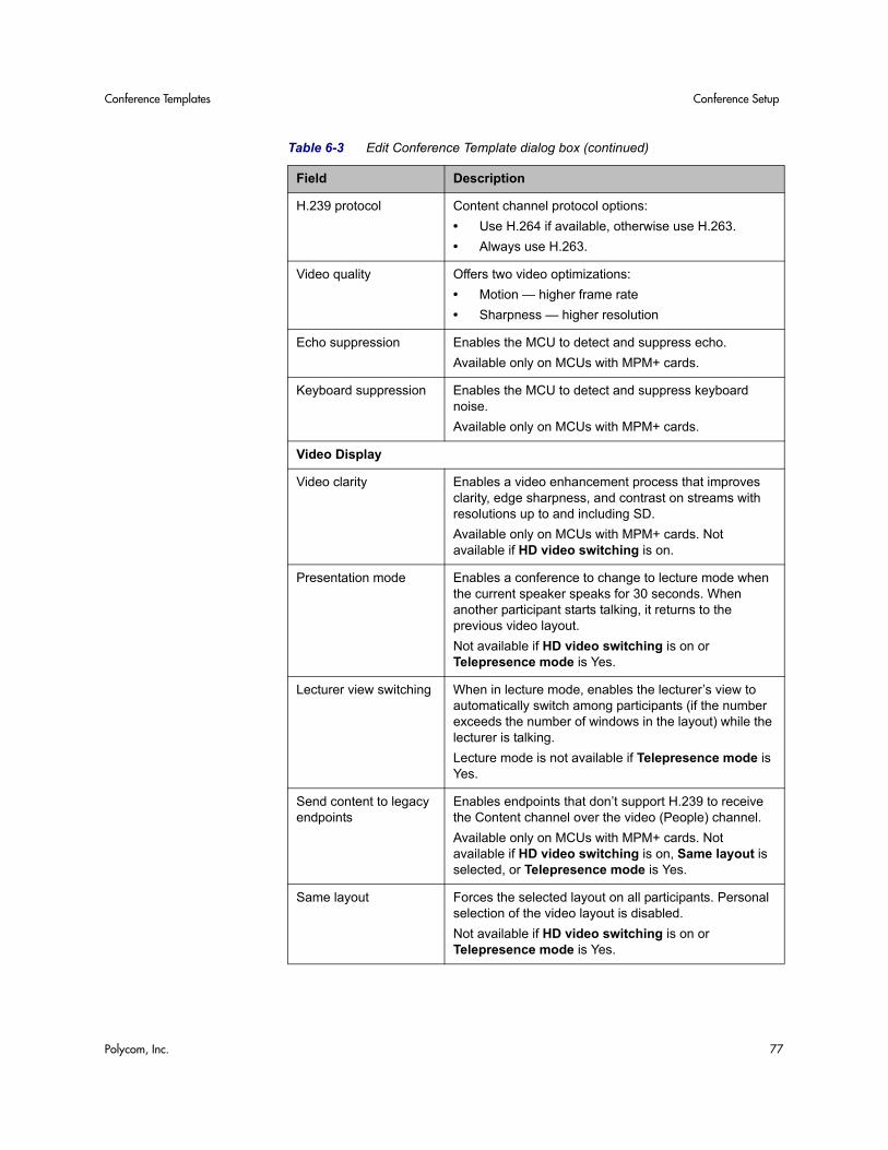
Conference Templates Conference Setup
Polycom, Inc. 77
H.239 protocol Content channel protocol options:
• Use H.264 if available, otherwise use H.263.
• Always use H.263.
Video quality Offers two video optimizations:
• Motion — higher frame rate
• Sharpness — higher resolution
Echo suppression Enables the MCU to detect and suppress echo.
Available only on MCUs with MPM+ cards.
Keyboard suppression Enables the MCU to detect and suppress keyboard noise.
Available only on MCUs with MPM+ cards.
Video Display
Video clarity Enables a video enhancement process that improves clarity, edge sharpness, and contrast on streams with resolutions up to and including SD.
Available only on MCUs with MPM+ cards. Not available if HD video switching is on.
Presentation mode Enables a conference to change to lecture mode when the current speaker speaks for 30 seconds. When another participant starts talking, it returns to the previous video layout.
Not available if HD video switching is on or Telepresence mode is Yes.
Lecturer view switching When in lecture mode, enables the lecturer’s view to automatically switch among participants (if the number exceeds the number of windows in the layout) while the lecturer is talking.
Lecture mode is not available if Telepresence mode is Yes.
Send content to legacy endpoints
Enables endpoints that don’t support H.239 to receive the Content channel over the video (People) channel.
Available only on MCUs with MPM+ cards. Not available if HD video switching is on, Same layout is selected, or Telepresence mode is Yes.
Same layout Forces the selected layout on all participants. Personal selection of the video layout is disabled.
Not available if HD video switching is on or Telepresence mode is Yes.
Table 6-3 Edit Conference Template dialog box (continued)
Field Description
DMA Operations Guide Conference Templates
78 Polycom, Inc.
Auto layout Lets the system select the video layout based on the number of participants in conference. Clear the check box to select a specific layout (below).
Not available if HD video switching is on or Telepresence mode is Yes.
Layout With Auto layout deselected, this opens the Select Layout dialog box, where you can select the number and arrangement of video frames. Once a layout is chosen, a small representation of it appears here. See “Select Layout Dialog Box” on page 79.
Not available if HD video switching is on.
Telepresence mode Support for telepresence conference rooms joining the conference:
• Auto (default) — A conference is automatically put into telepresence mode when a telepresence endpoint (RPX, TPX, or ATX) joins.
• Yes — Telepresence mode is on, regardless of whether a telepresence endpoint is present.
• No — Telepresence mode is off, regardless of whether a telepresence endpoint is present.
Available only on RMX v. 6.0 or later MCUs that are licensed for telepresence mode. We recommend always using Auto.
Telepresence layout mode
Layout choices for telepresence conferences:
• Manual — Layout is controlled manually by a conference operator using the Multipoint Layout Application (MLA) interface.
• Continuous Presence — Tells the MLA to generate a multipoint view (standard or custom).
• Room Switch — Tells the MLA to use Voice Activated Room Switching (VARS). The speaker’s site is the only one seen by others.
Not available if Telepresence mode is No. See the Polycom Multipoint Layout Application User Guide for more information about layouts.
Skins Lets you choose the display appearance (skin) for conferences using this template.
Not available if Telepresence mode is Yes.
Table 6-3 Edit Conference Template dialog box (continued)
Field Description
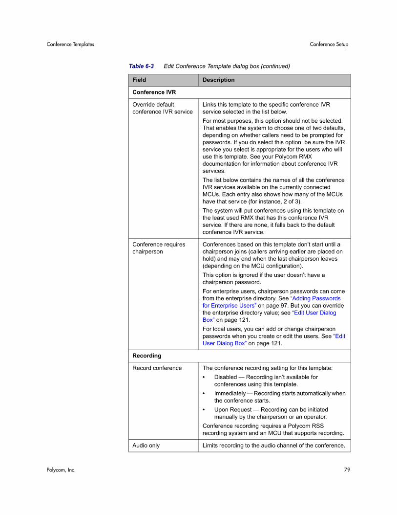
Conference Templates Conference Setup
Polycom, Inc. 79
Conference IVR
Override default conference IVR service
Links this template to the specific conference IVR service selected in the list below.
For most purposes, this option should not be selected. That enables the system to choose one of two defaults, depending on whether callers need to be prompted for passwords. If you do select this option, be sure the IVR service you select is appropriate for the users who will use this template. See your Polycom RMX documentation for information about conference IVR services.
The list below contains the names of all the conference IVR services available on the currently connected MCUs. Each entry also shows how many of the MCUs have that service (for instance, 2 of 3).
The system will put conferences using this template on the least used RMX that has this conference IVR service. If there are none, it falls back to the default conference IVR service.
Conference requires chairperson
Conferences based on this template don’t start until a chairperson joins (callers arriving earlier are placed on hold) and may end when the last chairperson leaves (depending on the MCU configuration).
This option is ignored if the user doesn’t have a chairperson password.
For enterprise users, chairperson passwords can come from the enterprise directory. See “Adding Passwords for Enterprise Users” on page 97. But you can override the enterprise directory value; see “Edit User Dialog Box” on page 121.
For local users, you can add or change chairperson passwords when you create or edit the users. See “Edit User Dialog Box” on page 121.
Recording
Record conference The conference recording setting for this template:
• Disabled — Recording isn’t available for conferences using this template.
• Immediately — Recording starts automatically when the conference starts.
• Upon Request — Recording can be initiated manually by the chairperson or an operator.
Conference recording requires a Polycom RSS recording system and an MCU that supports recording.
Audio only Limits recording to the audio channel of the conference.
Table 6-3 Edit Conference Template dialog box (continued)
Field Description
DMA Operations Guide Conference Templates
80 Polycom, Inc.
See also:
“Conference Templates Procedures” on page 80
“Conference Templates” on page 65
“Select Layout Dialog Box” on page 79
“Conference Settings” on page 82
“Calendaring Service” on page 83
Select Layout Dialog Box Lets you select a specific video frames layout when you’re adding or editing a conference template.
To select a video frames layout
1 Choose a Frame count value to see the layouts available for that value.
2 Click the one you want and click OK.
See also:
“Conference Templates Procedures” on page 80
“Add Conference Template Dialog Box” on page 69
“Edit Conference Template Dialog Box” on page 74
Conference Templates Procedures
To view the Conference Templates list
>> Go to Configuration > Conference Setup > Conference Templates.
The Conference Templates list appears.
To add a conference template not linked to an RMX profile
1 Go to Configuration > Conference Setup > Conference Templates.
2 In the Actions list, click Add.
3 In the Add Conference Template dialog box, specify all the conference properties for this template:
a In the General Info section, enter an appropriate name and description.
b To enable conferences using this template to cascade across multiple MCUs, check Cascaded conference.
Conference Templates Conference Setup
Polycom, Inc. 81
c Complete the Video Settings (Conference Settings and Video Display), Skins, Conference IVR, and Recording sections. See “Add Conference Template Dialog Box” on page 69.
4 Click OK.
The new template appears in the Conference Templates list.
To add a conference template linked to an RMX profile
1 Go to Configuration > Conference Setup > Conference Templates.
2 In the Actions list, click Add.
3 In the Add Conference Template dialog box, complete the General Info section:
a Enter an appropriate name and description.
b Check Use an existing profile and select the one you want from the RMX profile name list.
The list contains the profiles available on the RMX MCUs that have been added to the Polycom DMA system.
c To enable conferences using this template to cascade across multiple MCUs, check Cascaded conference.
4 Click OK.
The new template appears in the Conference Templates list.
To edit a conference template
1 Go to Configuration > Conference Setup > Conference Templates.
2 In the Conference Templates list, select the template of interest, and in the Actions list, click Edit.
3 In the Edit Conference Template dialog box, edit the General Info section. If not using an existing profile, edit the other sections as required. See “Edit Conference Template Dialog Box” on page 74.
4 Click OK.
The template changes appear in the Conference Templates list.
To change a conference template’s priority
1 Go to Configuration > Conference Setup > Conference Templates.
2 On the Conference Templates list, select the template whose priority you want to change.
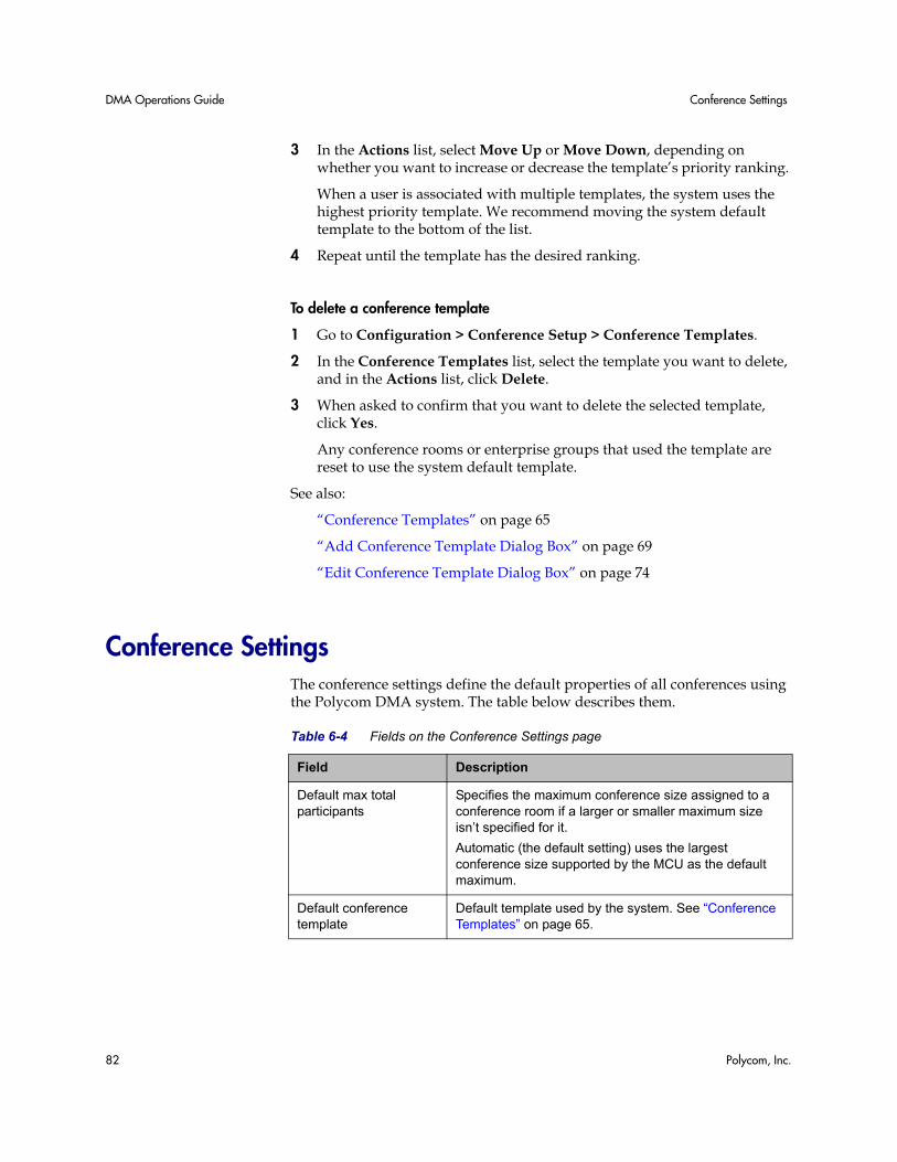
DMA Operations Guide Conference Settings
82 Polycom, Inc.
3 In the Actions list, select Move Up or Move Down, depending on whether you want to increase or decrease the template’s priority ranking.
When a user is associated with multiple templates, the system uses the highest priority template. We recommend moving the system default template to the bottom of the list.
4 Repeat until the template has the desired ranking.
To delete a conference template
1 Go to Configuration > Conference Setup > Conference Templates.
2 In the Conference Templates list, select the template you want to delete, and in the Actions list, click Delete.
3 When asked to confirm that you want to delete the selected template, click Yes.
Any conference rooms or enterprise groups that used the template are reset to use the system default template.
See also:
“Conference Templates” on page 65
“Add Conference Template Dialog Box” on page 69
“Edit Conference Template Dialog Box” on page 74
Conference Settings The conference settings define the default properties of all conferences using the Polycom DMA system. The table below describes them.
Table 6-4 Fields on the Conference Settings page
Field Description
Default max total participants
Specifies the maximum conference size assigned to a conference room if a larger or smaller maximum size isn’t specified for it.
Automatic (the default setting) uses the largest conference size supported by the MCU as the default maximum.
Default conference template
Default template used by the system. See “Conference Templates” on page 65.
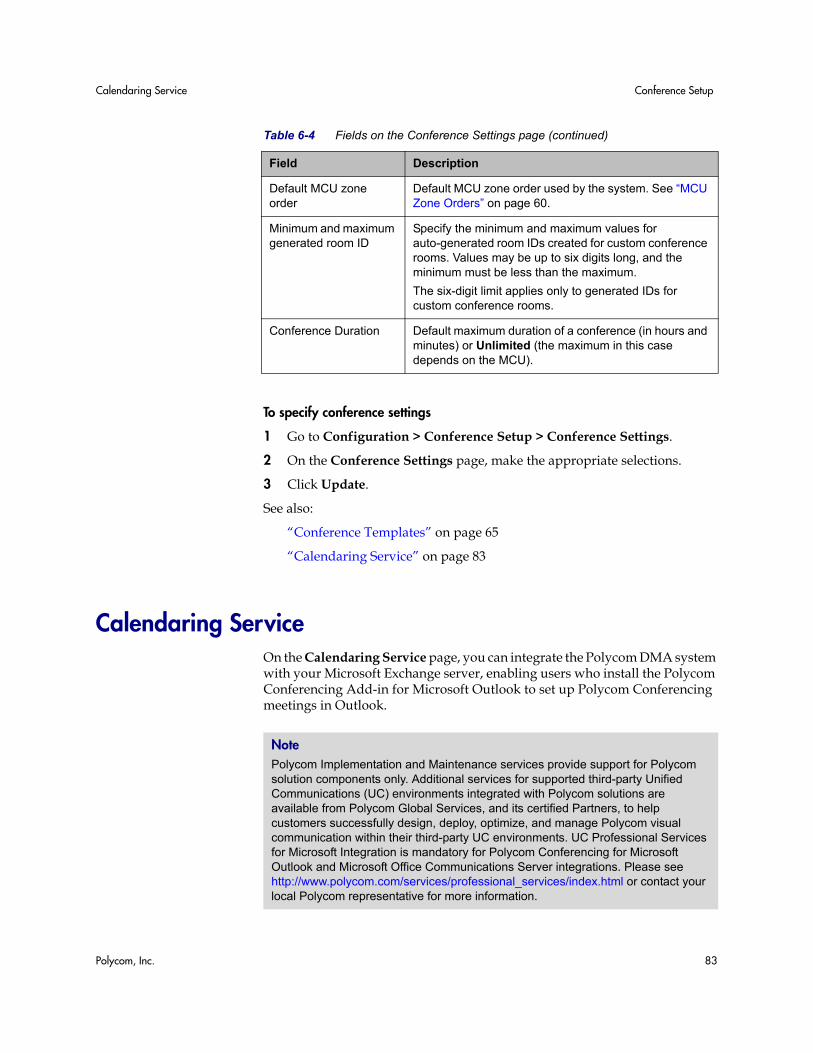
Calendaring Service Conference Setup
Polycom, Inc. 83
To specify conference settings
1 Go to Configuration > Conference Setup > Conference Settings.
2 On the Conference Settings page, make the appropriate selections.
3 Click Update.
See also:
“Conference Templates” on page 65
“Calendaring Service” on page 83
Calendaring Service On the Calendaring Service page, you can integrate the Polycom DMA system with your Microsoft Exchange server, enabling users who install the Polycom Conferencing Add-in for Microsoft Outlook to set up Polycom Conferencing meetings in Outlook.
Default MCU zone order
Default MCU zone order used by the system. See “MCU Zone Orders” on page 60.
Minimum and maximum generated room ID
Specify the minimum and maximum values for auto-generated room IDs created for custom conference rooms. Values may be up to six digits long, and the minimum must be less than the maximum.
The six-digit limit applies only to generated IDs for custom conference rooms.
Conference Duration Default maximum duration of a conference (in hours and minutes) or Unlimited (the maximum in this case depends on the MCU).
Table 6-4 Fields on the Conference Settings page (continued)
Field Description
Note Polycom Implementation and Maintenance services provide support for Polycom solution components only. Additional services for supported third-party Unified Communications (UC) environments integrated with Polycom solutions are available from Polycom Global Services, and its certified Partners, to help customers successfully design, deploy, optimize, and manage Polycom visual communication within their third-party UC environments. UC Professional Services for Microsoft Integration is mandatory for Polycom Conferencing for Microsoft Outlook and Microsoft Office Communications Server integrations. Please see http://www.polycom.com/services/professional_services/index.html or contact your local Polycom representative for more information.
DMA Operations Guide Calendaring Service
84 Polycom, Inc.
As with other Outlook meeting requests, the meeting organizer invites attendees and specifies where and when to meet. “Where” in this case is a conference room, or virtual meeting room (VMR), on the Polycom DMA system. The VMR number is generated by the add-in.
The invitees may include conference-room-based Polycom HDX systems as well as users with Polycom HDX personal conferencing endpoints. Polycom HDX systems monitor an Exchange mailbox (either their own or a linked user’s) for Polycom Conferencing meeting invitations.
Invitees with a desktop conferencing client (Microsoft Office Communicator or Polycom CMA Desktop) can join the meeting by clicking a link in the Outlook reminder or calendar. Invitees with a Polycom HDX endpoint can join by clicking a link on the HDX system’s reminder.
The add-in also sends Polycom Conferencing meeting invitations to a Polycom Conferencing user mailbox on the Exchange server. The Polycom DMA system monitors that mailbox and accepts or declines the invitations received.
A meeting invitation is declined if:
• The VMR number is in use by any other conference room (calendared, enterprise, or custom).
• The user sending the invitation isn’t in the Polycom DMA system’s enterprise directory cache.
• The invitation contains invalid or incomplete meeting data (the machine-readable metadata block at the bottom of the invitation labeled “POLYCOM VMR ENCODED TOKEN” and preceded with a warning not to edit).
• The meeting’s duration exceeds the system’s Conference Duration setting (see “Conference Settings” on page 82).
• The conference or chairperson password is not valid (see “Adding Passwords for Enterprise Users” on page 97).
The following table describes the fields on the Calendaring Service page.
Note Calendaring is not the same as scheduling. Using the Polycom Conferencing Add-in for Microsoft Outlook to set up a meeting appointment doesn’t reserve video resources, and invitations aren’t declined due to lack of resources.
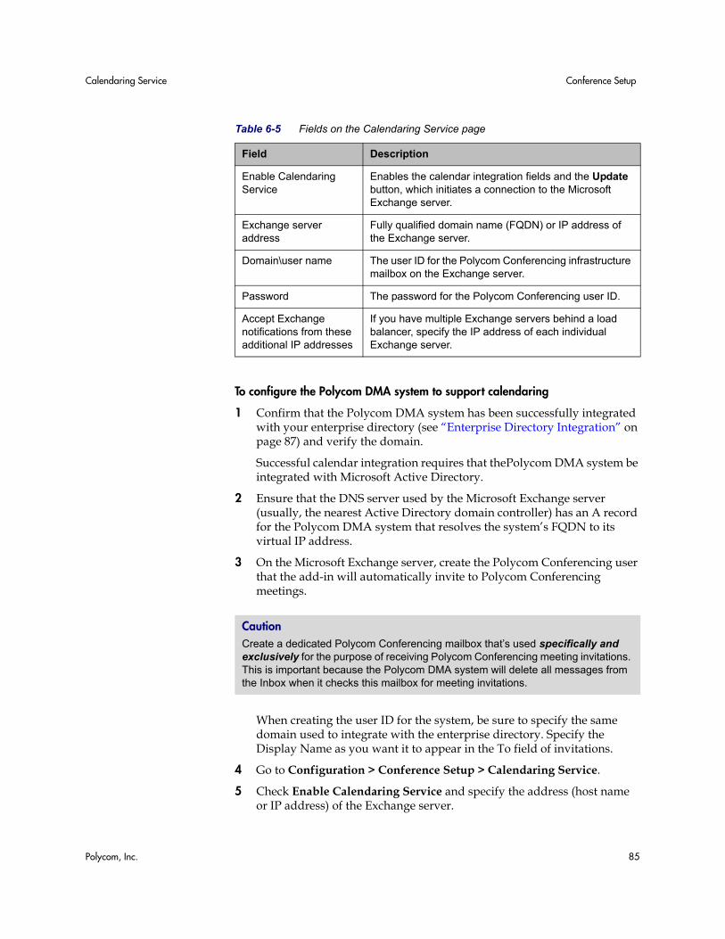
Calendaring Service Conference Setup
Polycom, Inc. 85
To configure the Polycom DMA system to support calendaring
1 Confirm that the Polycom DMA system has been successfully integrated with your enterprise directory (see “Enterprise Directory Integration” on page 87) and verify the domain.
Successful calendar integration requires that thePolycom DMA system be integrated with Microsoft Active Directory.
2 Ensure that the DNS server used by the Microsoft Exchange server (usually, the nearest Active Directory domain controller) has an A record for the Polycom DMA system that resolves the system’s FQDN to its virtual IP address.
3 On the Microsoft Exchange server, create the Polycom Conferencing user that the add-in will automatically invite to Polycom Conferencing meetings.
When creating the user ID for the system, be sure to specify the same domain used to integrate with the enterprise directory. Specify the Display Name as you want it to appear in the To field of invitations.
4 Go to Configuration > Conference Setup > Calendaring Service.
5 Check Enable Calendaring Service and specify the address (host name or IP address) of the Exchange server.
Table 6-5 Fields on the Calendaring Service page
Field Description
Enable Calendaring Service
Enables the calendar integration fields and the Update button, which initiates a connection to the Microsoft Exchange server.
Exchange server address
Fully qualified domain name (FQDN) or IP address of the Exchange server.
Domain\user name The user ID for the Polycom Conferencing infrastructure mailbox on the Exchange server.
Password The password for the Polycom Conferencing user ID.
Accept Exchange notifications from these additional IP addresses
If you have multiple Exchange servers behind a load balancer, specify the IP address of each individual Exchange server.
Caution Create a dedicated Polycom Conferencing mailbox that’s used specifically and exclusively for the purpose of receiving Polycom Conferencing meeting invitations. This is important because the Polycom DMA system will delete all messages from the Inbox when it checks this mailbox for meeting invitations.
DMA Operations Guide Calendaring Service
86 Polycom, Inc.
6 Specify the login credentials for the system on the Exchange server.
7 If you have multiple Exchange servers behind a load balancer, under Accept Exchange notifications from these additional IP addresses, add the IP address of each individual Exchange server.
8 Click Update.
A dialog box informs you that the configuration has been updated.
9 Click OK.
10 Install the Polycom Conferencing Add-in for Microsoft Outlook on your PC and create the configuration to be distributed to your users (see the online help for the Add-in). Optionally, customize the invitation template(s).
11 Distribute the Polycom Conferencing Add-in for Microsoft Outlook, its configuration file, and customized templates to your users (see the System Administrator Guide for the Polycom® Conferencing Add-in for Microsoft® Outlook®).
See also:
“Conference Templates” on page 65
“Conference Settings” on page 82
Polycom, Inc. 87
7Enterprise Directory Integration
This chapter describes the following Polycom® Distributed Media Application™ (DMA™) 7000 system configuration topics related to integrating the system with your enterprise directory:
• Enterprise Directory
• Enterprise Directory Integration Procedure
• Understanding Base DN
• Adding Passwords for Enterprise Users
• About the System’s Directory Queries
Enterprise Directory When you integrate the Polycom DMA system with your enterprise directory, the enterprise users (directory members) become Conferencing Users in the Polycom DMA system, and each is (optionally) assigned a conference room (virtual meeting room). The conference room IDs are typically generated from the enterprise users’ phone numbers.
Once integrated with an enterprise directory, the Polycom DMA system reads the directory information daily to update the user and group information in its cache. Between updates, it accesses the directory only to authenticate passwords.
Note Polycom Implementation and Maintenance services provide support for Polycom solution components only. Additional services for supported third-party Unified Communications (UC) environments integrated with Polycom solutions are available from Polycom Global Services, and its certified Partners, to help customers successfully design, deploy, optimize, and manage Polycom visual communication within their third-party UC environments. UC Professional Services for Microsoft Integration is mandatory for Polycom Conferencing for Microsoft Outlook and Microsoft Office Communications Server integrations. Please see http://www.polycom.com/services/professional_services/index.html or contact your local Polycom representative for more information.
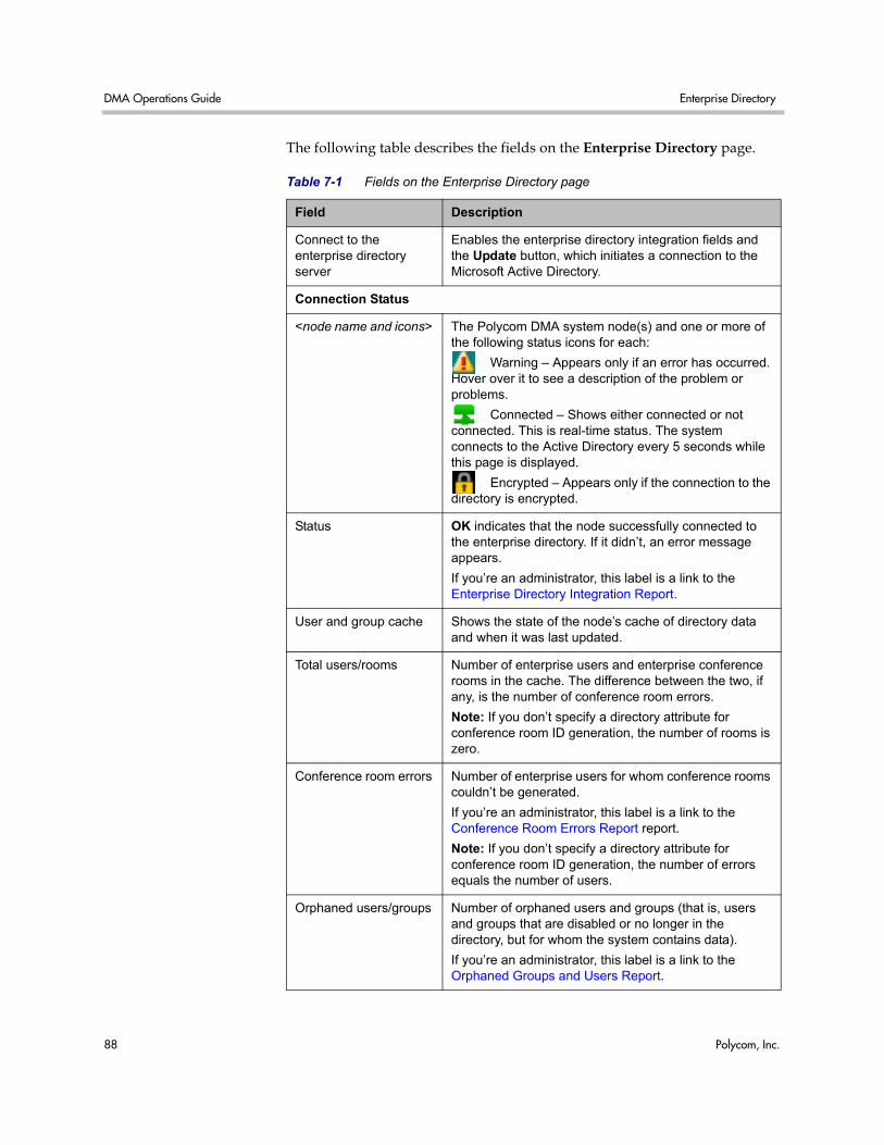
DMA Operations Guide Enterprise Directory
88 Polycom, Inc.
The following table describes the fields on the Enterprise Directory page.
Table 7-1 Fields on the Enterprise Directory page
Field Description
Connect to the enterprise directory server
Enables the enterprise directory integration fields and the Update button, which initiates a connection to the Microsoft Active Directory.
Connection Status
<node name and icons> The Polycom DMA system node(s) and one or more of the following status icons for each:
Warning – Appears only if an error has occurred. Hover over it to see a description of the problem or problems.
Connected – Shows either connected or not connected. This is real-time status. The system connects to the Active Directory every 5 seconds while this page is displayed.
Encrypted – Appears only if the connection to the directory is encrypted.
Status OK indicates that the node successfully connected to the enterprise directory. If it didn’t, an error message appears.
If you’re an administrator, this label is a link to the Enterprise Directory Integration Report.
User and group cache Shows the state of the node’s cache of directory data and when it was last updated.
Total users/rooms Number of enterprise users and enterprise conference rooms in the cache. The difference between the two, if any, is the number of conference room errors.
Note: If you don’t specify a directory attribute for conference room ID generation, the number of rooms is zero.
Conference room errors Number of enterprise users for whom conference rooms couldn’t be generated.
If you’re an administrator, this label is a link to the Conference Room Errors Report report.
Note: If you don’t specify a directory attribute for conference room ID generation, the number of errors equals the number of users.
Orphaned users/groups Number of orphaned users and groups (that is, users and groups that are disabled or no longer in the directory, but for whom the system contains data).
If you’re an administrator, this label is a link to the Orphaned Groups and Users Report.
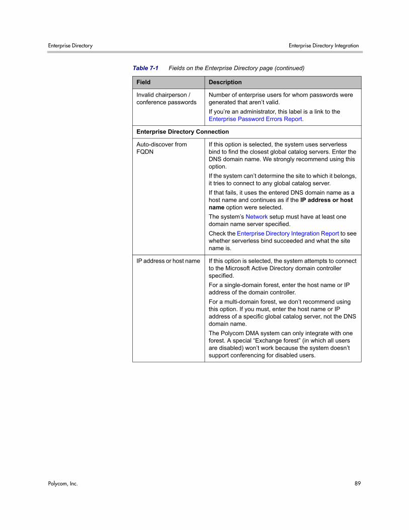
Enterprise Directory Enterprise Directory Integration
Polycom, Inc. 89
Invalid chairperson / conference passwords
Number of enterprise users for whom passwords were generated that aren’t valid.
If you’re an administrator, this label is a link to the Enterprise Password Errors Report.
Enterprise Directory Connection
Auto-discover from FQDN
If this option is selected, the system uses serverless bind to find the closest global catalog servers. Enter the DNS domain name. We strongly recommend using this option.
If the system can’t determine the site to which it belongs, it tries to connect to any global catalog server.
If that fails, it uses the entered DNS domain name as a host name and continues as if the IP address or host name option were selected.
The system’s Network setup must have at least one domain name server specified.
Check the Enterprise Directory Integration Report to see whether serverless bind succeeded and what the site name is.
IP address or host name If this option is selected, the system attempts to connect to the Microsoft Active Directory domain controller specified.
For a single-domain forest, enter the host name or IP address of the domain controller.
For a multi-domain forest, we don’t recommend using this option. If you must, enter the host name or IP address of a specific global catalog server, not the DNS domain name.
The Polycom DMA system can only integrate with one forest. A special “Exchange forest” (in which all users are disabled) won’t work because the system doesn’t support conferencing for disabled users.
Table 7-1 Fields on the Enterprise Directory page (continued)
Field Description
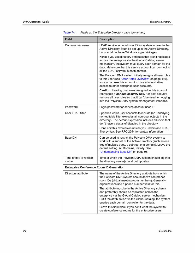
DMA Operations Guide Enterprise Directory
90 Polycom, Inc.
Domain\user name LDAP service account user ID for system access to the Active Directory. Must be set up in the Active Directory, but should not have Windows login privileges.
Note: If you use directory attributes that aren’t replicated across the enterprise via the Global Catalog server mechanism, the system must query each domain for the data. Make sure that this service account can connect to all the LDAP servers in each domain.
The Polycom DMA system initially assigns all user roles to this user (see “User Roles Overview” on page 116), so you can use this account to give administrative access to other enterprise user accounts.
Caution: Leaving user roles assigned to this account represents a serious security risk. For best security, remove all user roles so that it can’t be used for logging into the Polycom DMA system management interface.
Password Login password for service account user ID.
User LDAP filter Specifies which user accounts to include (an underlying, non-editable filter excludes all non-user objects in the directory). The default expression includes all users that don’t have a status of disabled in the directory.
Don’t edit this expression unless you understand LDAP filter syntax. See RFC 2254 for syntax information.
Base DN Can be used to restrict the Polycom DMA system to work with a subset of the Active Directory (such as one tree of multiple trees, a subtree, or a domain). Leave the default setting, All Domains, initially. See “Understanding Base DN” on page 95.
Time of day to refresh cache
Time at which the Polycom DMA system should log into the directory server(s) and get updates.
Enterprise Conference Room ID Generation
Directory attribute The name of the Active Directory attribute from which the Polycom DMA system should derive conference room IDs (virtual meeting room numbers). Generally, organizations use a phone number field for this.
The attribute must be in the Active Directory schema and preferably should be replicated across the enterprise via the Global Catalog server mechanism. But if the attribute isn’t in the Global Catalog, the system queries each domain controller for the data.
Leave this field blank if you don’t want the system to create conference rooms for the enterprise users.
Table 7-1 Fields on the Enterprise Directory page (continued)
Field Description
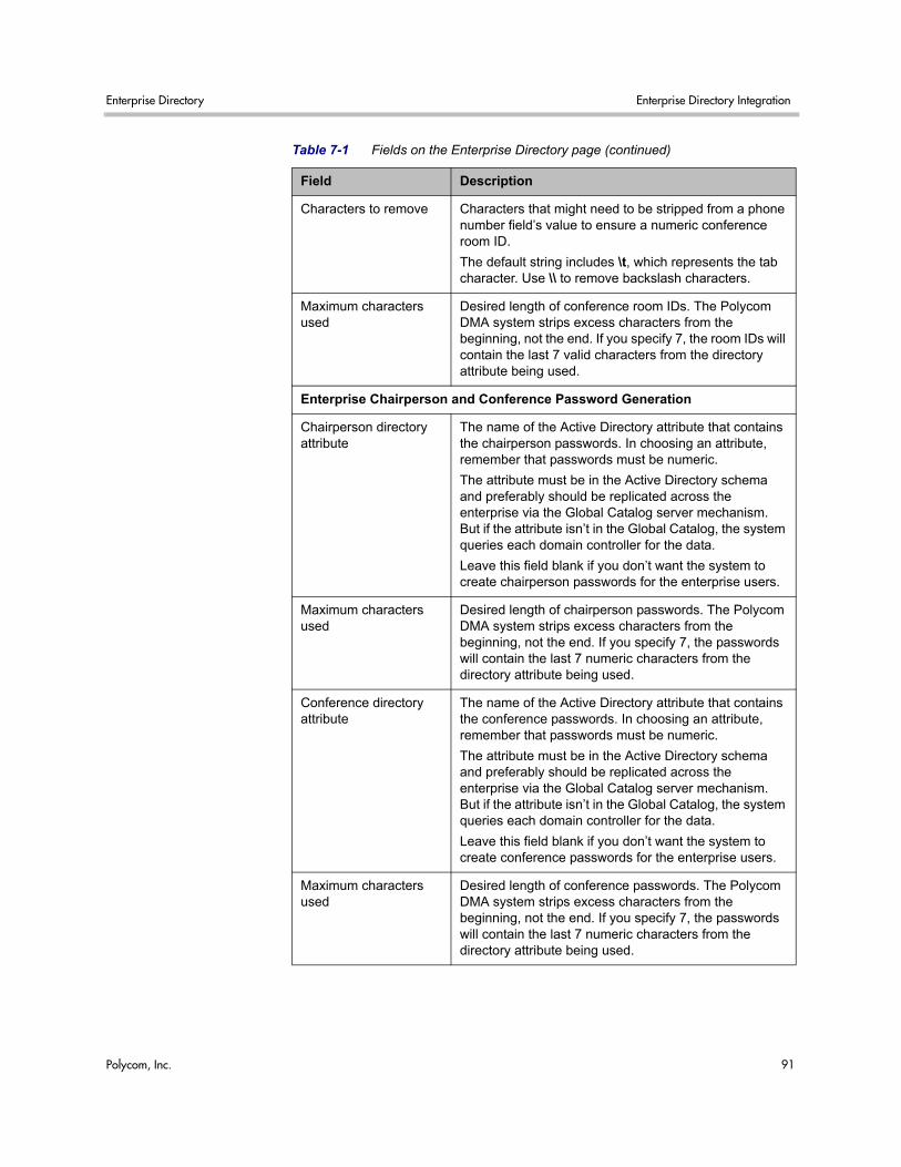
Enterprise Directory Enterprise Directory Integration
Polycom, Inc. 91
Characters to remove Characters that might need to be stripped from a phone number field’s value to ensure a numeric conference room ID.
The default string includes \t, which represents the tab character. Use \\ to remove backslash characters.
Maximum characters used
Desired length of conference room IDs. The Polycom DMA system strips excess characters from the beginning, not the end. If you specify 7, the room IDs will contain the last 7 valid characters from the directory attribute being used.
Enterprise Chairperson and Conference Password Generation
Chairperson directory attribute
The name of the Active Directory attribute that contains the chairperson passwords. In choosing an attribute, remember that passwords must be numeric.
The attribute must be in the Active Directory schema and preferably should be replicated across the enterprise via the Global Catalog server mechanism. But if the attribute isn’t in the Global Catalog, the system queries each domain controller for the data.
Leave this field blank if you don’t want the system to create chairperson passwords for the enterprise users.
Maximum characters used
Desired length of chairperson passwords. The Polycom DMA system strips excess characters from the beginning, not the end. If you specify 7, the passwords will contain the last 7 numeric characters from the directory attribute being used.
Conference directory attribute
The name of the Active Directory attribute that contains the conference passwords. In choosing an attribute, remember that passwords must be numeric.
The attribute must be in the Active Directory schema and preferably should be replicated across the enterprise via the Global Catalog server mechanism. But if the attribute isn’t in the Global Catalog, the system queries each domain controller for the data.
Leave this field blank if you don’t want the system to create conference passwords for the enterprise users.
Maximum characters used
Desired length of conference passwords. The Polycom DMA system strips excess characters from the beginning, not the end. If you specify 7, the passwords will contain the last 7 numeric characters from the directory attribute being used.
Table 7-1 Fields on the Enterprise Directory page (continued)
Field Description
DMA Operations Guide Enterprise Directory Integration Procedure
92 Polycom, Inc.
See also:
“Enterprise Directory Integration Procedure” on page 92
“Understanding Base DN” on page 95
“Adding Passwords for Enterprise Users” on page 97
“About the System’s Directory Queries” on page 99
“Enterprise Directory Integration Report” on page 169
“Conference Room Errors Report” on page 173
“Groups” on page 130
“Enterprise Groups Procedures” on page 132
Enterprise Directory Integration Procedure Before performing the procedure below, read “Set Up Security” on page 11 and “Connect to an Enterprise Directory” on page 13. You should also have a good idea of how many enterprise users you expect the system to retrieve.
To connect to an enterprise directory
1 In Windows Server 2003, add the service account (read-only user account) that the Polycom DMA system will use to read the enterprise directory. Configure this account as follows:
— User can’t change password.
— Password never expires.
— User can only access services on the domain controllers and cannot log in anywhere.
2 In the Polycom DMA system, replace the default local administrative user with your own user account that has the same user roles. See “Users Procedures” on page 127.
3 Log into the Polycom DMA system as the local user you created in step 2 and go to Configuration > System > Enterprise Directory.
4 Check Connect to the enterprise directory server and complete the information in the Enterprise Directory Connection section.
Note If you use directory attributes that aren’t replicated across the enterprise via the Global Catalog server mechanism, the system must query each domain for the data. Make sure that this service account can connect to all the LDAP servers in each domain.
Enterprise Directory Integration Procedure Enterprise Directory Integration
Polycom, Inc. 93
a Unless you have a single domain environment and no global catalog, select Auto-discover from FQDN and enter the DNS domain name.
b For Domain\user name, enter the domain and user ID of the account you created in step 1.
c Leave Base DN set to the default, All Domains. Don’t edit the LDAP filter expression unless you understand LDAP filter syntax (see RFC 2254) and know what changes to make.
d Specify the time each day that you want the Polycom DMA system to check the enterprise directory for changes.
5 To generate conference room IDs for the enterprise users, complete the Enterprise Conference Room ID Generation section.
Skip this step if you don’t want the system to create conference rooms (virtual meeting rooms) for the enterprise users.
a Specify the directory attribute from which to generate room IDs.
Your users will be happier if room IDs are numeric and not longer than necessary to ensure uniqueness. Phone numbers are the most likely choice, or maybe employee ID numbers.
b If necessary, edit the contents of the Characters to remove field.
If you use phone numbers, the default contents of this field should work to ensure a numeric room ID.
c Specify the number of characters to use.
After the system strips out characters to remove, it removes characters in excess of this number from the beginning of the string.
6 Click Update.
After a short time, the system confirms that enterprise directory configuration has been updated.
7 Note the time. Click OK.
Note We don’t recommend using the IP address or host name option in a multi-domain environment. If you must, enter the host name or IP address of a specific global catalog server, not the DNS domain name.
Note Leave the Enterprise Chairperson and Conference Password Generation section alone for now. Once the system is integrated successfully, if you want to add password support, see “Adding Passwords for Enterprise Users” on page 97.
DMA Operations Guide Enterprise Directory Integration Procedure
94 Polycom, Inc.
8 To restrict the Polycom DMA system to work with a subset of the Active Directory (such as one tree of multiple trees, a subtree, or a domain), repeat steps 4-6, selecting the value you want from those now available in the Base DN list. See “Understanding Base DN” on page 95.
9 Check the Total users/rooms and Conference room errors values. If the numbers are significantly different from what you expected, you’ll need to investigate after you complete the next step (you must be logged in as an enterprise user to investigate further).
10 Set up your enterprise account and secure the service account:
a Log out and log back in using the service account you created in step 1.
You must be logged in with an enterprise directory user account to see other enterprise users. The service account user ID specified in step 4b lets you do so initially.
b Go to Operations > Users, locate your named enterprise account, and give it Administrator privileges. See “User Roles Overview” on page 116 and “Users Procedures” on page 127.
c Log out and log back in using your named enterprise account.
d Secure the service account by removing all user roles in the Polycom DMA system. See “Edit User Dialog Box” on page 121.
11 If, in step 9, the Total users/rooms values were significantly different from what you expected, try to determine the reason and fix it:
a Go to Operations > Users and perform some searches to determine which enterprise users are available and which aren’t.
b If there are many missing or incorrect users, consider whether changes to the LDAP filter can correct the problem or if there is an issue with the directory integration configuration chosen.
12 If, in step 9, there were many conference room errors, try to determine the reason and fix it:
a Go to Reports > Conference Room Errors and verify that the time on the report is after the time when you last completed step 4.
Caution Leaving user roles assigned to the service account represents a serious security risk. For best security, remove all user roles so that it can’t be used for logging into the Polycom DMA system management interface.
Note If you’re not familiar with LDAP filter syntax (as defined in RFC 2254) and knowledgeable about enterprise directories in general and your specific implementation in particular, please consult with someone who is.
Understanding Base DN Enterprise Directory Integration
Polycom, Inc. 95
b Review the list of duplicate and invalid conference room IDs. Consider whether using a different directory attribute, increasing the conference room ID length, or editing the characters to remove will resolve the majority of problems.
If there are only a few problems, they can generally be resolved by correcting invalid enterprise directory entries.
13 If necessary, repeat steps 4-9 and steps 11 and/or 12, modifying the integration parameters as needed, until you get a satisfactory result.
See also:
“Enterprise Directory” on page 87
“Understanding Base DN” on page 95
“About the System’s Directory Queries” on page 99
“Enterprise Directory Integration Report” on page 169
“Conference Room Errors Report” on page 173
“Groups” on page 130
“Enterprise Groups Procedures” on page 132
Understanding Base DN The Base DN field is where you can specify the distinguished name (DN) of a subset of the Active Directory hierarchy (a domain, subset of domains, or organizational unit) to which you want to restrict the Polycom DMA system. It acts like a filter.
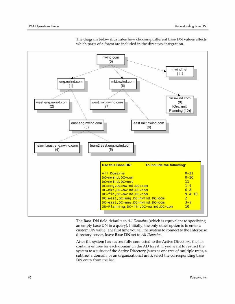
DMA Operations Guide Understanding Base DN
96 Polycom, Inc.
The diagram below illustrates how choosing different Base DN values affects which parts of a forest are included in the directory integration.
The Base DN field defaults to All Domains (which is equivalent to specifying an empty base DN in a query). Initially, the only other option is to enter a custom DN value. The first time you tell the system to connect to the enterprise directory server, leave Base DN set to All Domains.
After the system has successfully connected to the Active Directory, the list contains entries for each domain in the AD forest. If you want to restrict the system to a subset of the Active Directory (such as one tree of multiple trees, a subtree, a domain, or an organizational unit), select the corresponding base DN entry from the list.
eng.nwind.com(1)
mkt.nwind.com(6)
west.eng.nwind.com(2)
east.eng.nwind.com(3)
west.mkt.nwind.com(7)
east.mkt.nwind.com(8)
team1.east.eng.nwind.com(4)
fin.nwind.com(9)
[Org. unit:Planning (10)]
team2.east.eng.nwind.com(5)
Use this Base DN: To include the following:
All Domains 0-11DC=nwind,DC=com 0-10DC=nwind,DC=net 11DC=eng,DC=nwind,DC=com 1-5DC=mkt,DC=nwind,DC=com 6-8DC=fin,DC=nwind,DC=com 9 & 10DC=west,DC=eng,DC=nwind,DC=com 2DC=east,DC=eng,DC=nwind,DC=com 3-5OU=Planning,DC=fin,DC=nwind,DC=com 10
nwind.com(0)
nwind.net(11)
Adding Passwords for Enterprise Users Enterprise Directory Integration
Polycom, Inc. 97
See also:
“Enterprise Directory” on page 87
“Enterprise Directory Integration Procedure” on page 92
“About the System’s Directory Queries” on page 99
Adding Passwords for Enterprise Users Polycom RMX MCUs provide two optional security features for conferences, which the Polycom DMA system fully supports:
• Conference Password — A numeric password that callers must enter in order to join the conference.
• Chairperson Password — A numeric password that callers can enter to identify themselves as conference chairpersons. Chairpersons have additional privileges, such as controlling recording. A conference can be configured to not start until a chairperson joins and to end when the last chairperson leaves (see “Add Conference Template Dialog Box” on page 69).
If the Polycom DMA system is integrated with your enterprise directory, conference and chairperson passwords for enterprise users can be maintained in the enterprise directory.
You must determine which directory attributes to use for the purpose and provide a process for provisioning users with those passwords. If a user’s password directory attribute (either conference or chairperson) is left empty, the user’s conferences won’t require that password.
Passwords must consist of numeric characters only (the digits 0-9). You can specify the maximum length for each password type (up to 16 digits). A user’s conference and chairperson passwords can’t be the same.
When you generate passwords for enterprise users, the Polycom DMA system retrieves the values in the designated directory attributes and removes any non-numeric characters from them. If the resulting numeric password is longer than the maximum for that password type, it strips the excess characters from the beginning of the string.
To generate chairperson and conference passwords for enterprise users
1 In the enterprise directory, select an unused attribute to be used for each of the passwords.
In a multi-domain forest, it’s best to choose attributes that are replicated across the enterprise via the Global Catalog server mechanism. But if the attributes you select aren’t available in the Global Catalog, the system can read them directly from each domain.
DMA Operations Guide Adding Passwords for Enterprise Users
98 Polycom, Inc.
2 Either provision users with passwords or establish a mechanism for letting users create and maintain their own passwords.
3 On the Polycom DMA system, go to Configuration > System > Enterprise Directory.
4 Complete the Enterprise Chairperson and Conference Password Generation section.
a Specify the directory attribute from which to generate chairperson passwords and the number of characters to use.
b Specify the directory attribute from which to generate conference passwords and the number of characters to use.
5 Click Update.
After a short time, the system confirms that enterprise directory configuration has been updated.
6 Note the time. Click OK.
7 Confirm that password generation worked as expected.
a Go to System Management > Reports > Enterprise Password Errors and verify that the time on the report is after the time when you last completed step 6.
b Review the number of valid, invalid, and unassigned passwords.
If there are only a few problems, they can generally be resolved by correcting invalid enterprise directory entries.
Note You could use an existing attribute that contains numeric data, such as an employee ID. This may not provide much security, but might be sufficient for conference passwords.
Note Unless users have already been provisioned with passwords or you’re using an existing attribute, most users will probably not have passwords assigned. Duplicate and invalid passwords should be your main concern because they could indicate a problem with the type of data in the selected attributes or with the number of characters you elected to use.
About the System’s Directory Queries Enterprise Directory Integration
Polycom, Inc. 99
About the System’s Directory Queries The Polycom DMA system uses the following subtree scope LDAP queries. In a standard AD configuration, all these queries use indexes.
• User Search
• Group Search
• Global Group Membership Search
• Attribute Replication Search
• Configurable Attribute Domain Search
• Domain Search
• Service Account Search
The system runs the first three queries every time it creates or updates its cache:
• When you click Update on the Enterprise directory page
• When the system restarts (if integrated with the enterprise directory)
• At the scheduled daily cache refresh time
The elements in italics are examples. The actual values of these variables depend on your configuration.
User Search This search queries the global catalog. In a standard AD configuration, all the filter attributes and attributes returned are replicated to the global catalog.
• Base: <empty>
The base variable depends on the Base DN setting on the Enterprise Directory page. If it’s set to the default, All Domains, the base variable is empty, as shown. Otherwise, the base variable is the same as Base DN. See “Understanding Base DN” on page 95.
• Filter: (&(objectCategory=person)(UserAccountControl:1.2.840.113556.1.4.803:=512)(sAMAccountName=*)(!(userAccountControl:1.2.840.113556.1.4.803:=2)))
The filter variable depends on the User LDAP filter setting. See “Enterprise Directory” on page 87.
• Index used: idx_objectCategory:32561:N
The search used this index in our testing environment, using a standard AD configuration (no indexes added). Results may be different for a different configuration, especially a different User LDAP filter setting.
DMA Operations Guide About the System’s Directory Queries
100 Polycom, Inc.
• Attributes returned: sAMAccountName, userAccountControl, givenName, sn, [telephoneNumber], [chairpassword], [confpassword]
The three attributes returned variables (in square brackets) are returned only if you specify the corresponding directory attributes (for generating conference room IDs, chairperson passwords, and conference passwords, respectively) and if the Attribute Replication Search determined that the attributes are replicated to the global catalog.
See “Enterprise Directory” on page 87 and “Adding Passwords for Enterprise Users” on page 97.
Group Search This search queries the global catalog. In a standard AD configuration, all the filter attributes and attributes returned are replicated to the global catalog.
• Base: <empty>
The base variable depends on the Base DN setting on the Enterprise Directory page. If it’s set to the default, All Domains, the base variable is empty, as shown. Otherwise, the base variable is the same as Base DN. See “Understanding Base DN” on page 95.
• Filter: (&(objectClass=group)(|(groupType=-2147483640)(groupType=-2147483646)))
• Indexes used: idx_groupType:6675:N;idx_groupType:11:N
The search used these indexes in our testing environment, using a standard AD configuration (no indexes added). Results may be different for a different configuration.
• Attributes returned: cn, description, sAMAccountName, groupType, member
Global Group Membership Search This search queries LDAP.
• Base: DC=dma,DC=eng,DC=local
The base variable depends on the Base DN setting on the Enterprise Directory page. If it’s set to the default, All Domains, the base variable is the domain DN, as shown by the example. Otherwise, the base variable is the same as Base DN. See “Understanding Base DN” on page 95.
• Filter: (&(objectClass=group)(groupType=-2147483646))
• Index used: idx_groupType:6664:N
The search used this index in our testing environment, using a standard AD configuration (no indexes added). Results may be different for a different configuration.
About the System’s Directory Queries Enterprise Directory Integration
Polycom, Inc. 101
• Attributes returned: member
Attribute Replication Search This search queries LDAP.
The system runs this query when it restarts (if already integrated with the enterprise directory) and when you click the Update button on the Enterprise Directory page, but only if one or more of the configurable directory attributes (for generating conference room IDs, chairperson passwords, and conference passwords) is specified.
The purpose of this query is simply to determine if those directory attributes are replicated to the global catalog. If they are, the User Search retrieves them. If any of them isn’t, the system uses the Configurable Attribute Domain Search to retrieve the data from each domain controller.
• Base: CN=Schema,CN=Configuration,DC=dma,DC=eng,DC=local
The base variable depends on the forest root.
• Filter: (|(lDAPDisplayName=telephoneNumber)(lDAPDisplayName=chairpassword)(lDAPDisplayName=confpassword))
The filter variables depend on the configurable directory attributes specified in the Enterprise Conference Room ID Generation and Enterprise Chairperson and Conference Password Generation sections (any of these that’s empty is omitted from the filter).
• Indexes used: idx_lDAPDisplayName:3:N;idx_lDAPDisplayName:2:N; idx_lDAPDisplayName:1:N
The search used these indexes in our testing environment, using a standard AD configuration (no indexes added). Results may be different for a different configuration.
• Attributes returned: lDAPDisplayName, isMemberOfPartialAttributeSet
Configurable Attribute Domain Search This search queries LDAP.
The system runs this query only if the Attribute Replication Search determined that one or more of the configurable directory attributes that it needs to retrieve (for generating conference room IDs, chairperson passwords, and conference passwords) isn’t in the global catalog. In that case, it uses this query to retrieve the data from each domain controller.
• Base: DC=dma,DC=eng,DC=local
The base variable depends on the domain name being queried.
• Filter: same as in User Search
DMA Operations Guide About the System’s Directory Queries
102 Polycom, Inc.
• Index used: same as in User Search
• Attributes returned: sAMAccountName, attribute(s) not in global catalog
Domain Search This search queries LDAP.
The system runs this query only when it restarts (if already integrated with the enterprise directory) and when you click the Update button on the Enterprise Directory page.
• Base: CN=Configuration,DC=dma,DC=eng,DC=local
The base variable depends on the forest root DN (the distinguished name of the Active Directory forest root domain). See “Enterprise Directory Integration Report” on page 169.
• Filter: (&(objectCategory=crossRef)(systemFlags=3))
• Indexes used: idx_objectCategory:11:N
The search used these indexes in our testing environment, using a standard AD configuration (no indexes added). Results may be different for a different configuration.
• Attributes returned: cn, dnsRoot, nCName
Service Account Search This search queries the global catalog. In a standard AD configuration, all the filter attributes and attributes returned are replicated to the global catalog.
The system runs this query only when you click the Update button on the Enterprise Directory page. It validates the service account ID.
• Base: <empty>
The base variable depends on the Base DN setting on the Enterprise Directory page. If it’s set to the default, All Domains, the base variable is empty, as shown. Otherwise, the base variable is the same as Base DN. See “Understanding Base DN” on page 95.
• Filter: (&(objectCategory=person)(UserAccountControl:1.2.840.113556.1.4.803:=512)(sAMAccountName=*)(&(!(userAccountControl:1.2.840.113556.1.4.803:=2))(sAMAccountName=<userID>)))
The first filter variable depends on the User LDAP filter setting. See “Enterprise Directory” on page 87. The second variable depends on the value entered in the Service account ID field on the Enterprise Directory page. See “Enterprise Directory” on page 87.
• Index used: idx_objectCategory:32561:N
About the System’s Directory Queries Enterprise Directory Integration
Polycom, Inc. 103
The search used this index in our testing environment, using a standard AD configuration (no indexes added). Results may be different for a different configuration, especially a different User LDAP filter setting.
• Attributes returned: sAMAccountName, userAccountControl, givenName, sn
See also:
“Enterprise Directory” on page 87
“Enterprise Directory Integration Procedure” on page 92
“Understanding Base DN” on page 95

DMA Operations Guide About the System’s Directory Queries
104 Polycom, Inc.
Polycom, Inc. 105
8Site Topology Configuration
This chapter describes the following Polycom® Distributed Media Application™ (DMA™) 7000 site topology configuration topics:
• About Site Topology
• Sites
• Site Links
• Site-to-Site Exclusions
• Network Clouds
• Site Topology Configuration Procedures
About Site Topology Site topology information describes your network and its interfaces to other networks, including the following elements:
• Site — A local area network (LAN) that generally corresponds with a geographic location such as an office or plant. A site contains one or more network subnets, so a device’s IP address identifies the site to which it belongs.
• Network cloud — A Multiprotocol Label Switching (MPLS) network cloud defined in the site topology. An MPLS network is a private network that links multiple locations and uses label switching to tag packets with origin, destination, and quality of service (QOS) information.
• Site link — A network connection between two sites or between a site and an MPLS network cloud.
• Site-to-site exclusion — A site-to-site connection that the site topology doesn’t permit an audio or video call to use.
The Polycom DMA system needs site topology information in order to support cascading of conferences. It can get it in one of two ways:
DMA Operations Guide Sites
106 Polycom, Inc.
• If you have a Polycom CMA 5000 system, integrate the Polycom DMA system with it (see “CMA Integration” on page 24) to automatically get its site topology information.
• If you don’t have a Polycom CMA 5000 system, enter site topology information about your network directly into the Polycom DMA system’s site topology pages.
For a conference with cascading enabled, the Polycom DMA system uses the site topology information to route calls to the nearest eligible MCU (based on zones and zone orders) that has available capacity and to create the cascade links between MCUs.
When determining which MCU is “nearest” to a caller and which path is best for a cascade link, the system takes into account the bandwidth availability of alternative paths.
Sites The Sites page contains a list of the sites defined in the site topology.
If the system is integrated with a Polycom CMA system, it receives this information from that system, and this page is read-only. If not, you can enter site information.
The commands in the Actions list let you add a site, edit or delete existing sites, and see information about a site.
The following table describes the fields in the list.
Site Information Dialog Box Lets you view information about the selected site, including which subnets are associated with it.
Note Cascading always uses a hub-and-spoke configuration so that each cascaded MCU is only one link away from the “hub” MCU.
RMX MCUs support cascade links only in H.323, so the bridges and Polycom DMA system must be configured to support H.323 signaling in order to enable cascading.
Table 8-1 Information in the Sites list
Column Description
Name Name of the site.
Description Description of the site.
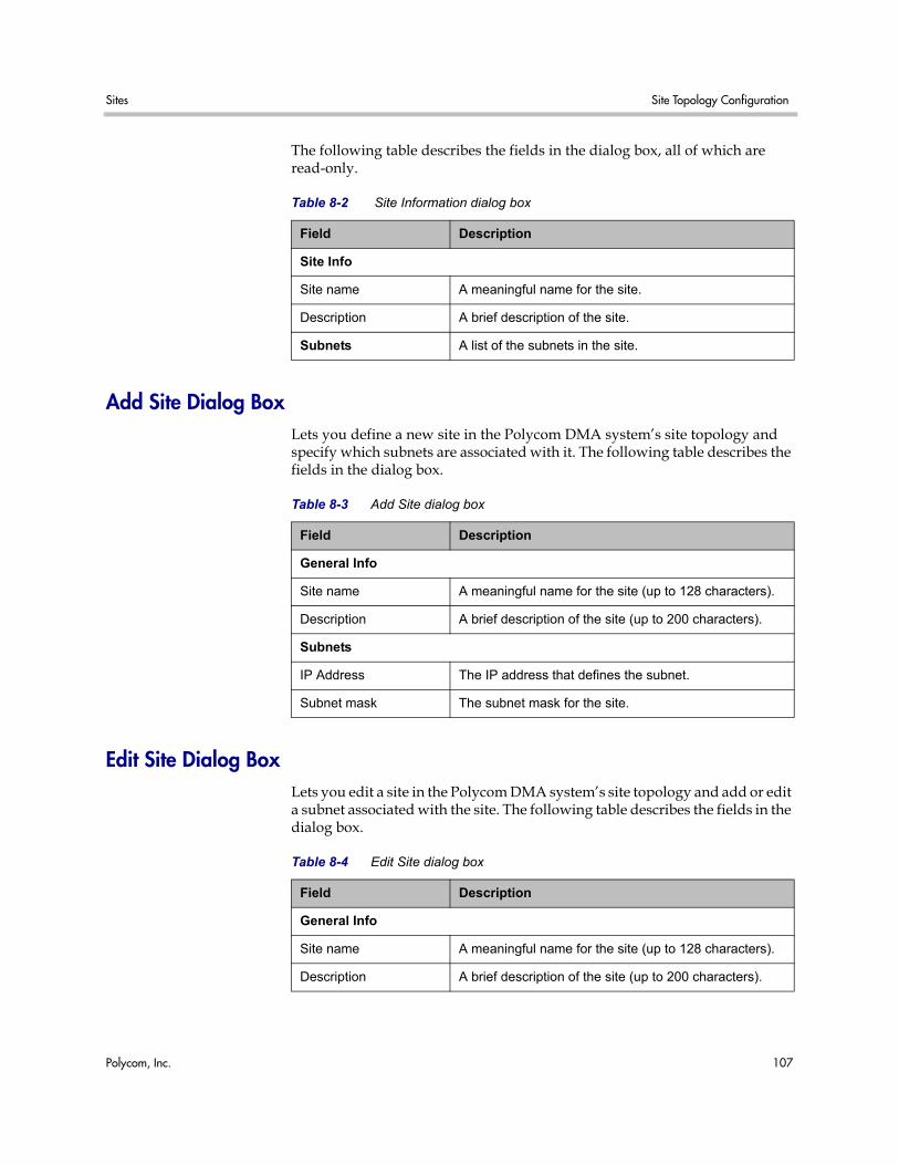
Sites Site Topology Configuration
Polycom, Inc. 107
The following table describes the fields in the dialog box, all of which are read-only.
Add Site Dialog Box Lets you define a new site in the Polycom DMA system’s site topology and specify which subnets are associated with it. The following table describes the fields in the dialog box.
Edit Site Dialog Box Lets you edit a site in the Polycom DMA system’s site topology and add or edit a subnet associated with the site. The following table describes the fields in the dialog box.
Table 8-2 Site Information dialog box
Field Description
Site Info
Site name A meaningful name for the site.
Description A brief description of the site.
Subnets A list of the subnets in the site.
Table 8-3 Add Site dialog box
Field Description
General Info
Site name A meaningful name for the site (up to 128 characters).
Description A brief description of the site (up to 200 characters).
Subnets
IP Address The IP address that defines the subnet.
Subnet mask The subnet mask for the site.
Table 8-4 Edit Site dialog box
Field Description
General Info
Site name A meaningful name for the site (up to 128 characters).
Description A brief description of the site (up to 200 characters).
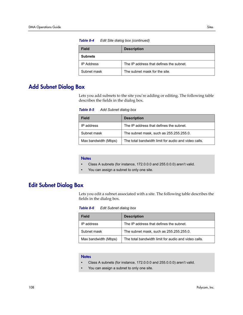
DMA Operations Guide Sites
108 Polycom, Inc.
Add Subnet Dialog Box Lets you add subnets to the site you’re adding or editing. The following table describes the fields in the dialog box.
Edit Subnet Dialog Box Lets you edit a subnet associated with a site. The following table describes the fields in the dialog box.
Subnets
IP Address The IP address that defines the subnet.
Subnet mask The subnet mask for the site.
Table 8-4 Edit Site dialog box (continued)
Field Description
Table 8-5 Add Subnet dialog box
Field Description
IP address The IP address that defines the subnet.
Subnet mask The subnet mask, such as 255.255.255.0.
Max bandwidth (Mbps) The total bandwidth limit for audio and video calls.
Notes • Class A subnets (for instance, 172.0.0.0 and 255.0.0.0) aren’t valid.
• You can assign a subnet to only one site.
Table 8-6 Edit Subnet dialog box
Field Description
IP address The IP address that defines the subnet.
Subnet mask The subnet mask, such as 255.255.255.0.
Max bandwidth (Mbps) The total bandwidth limit for audio and video calls.
Notes • Class A subnets (for instance, 172.0.0.0 and 255.0.0.0) aren’t valid.
• You can assign a subnet to only one site.
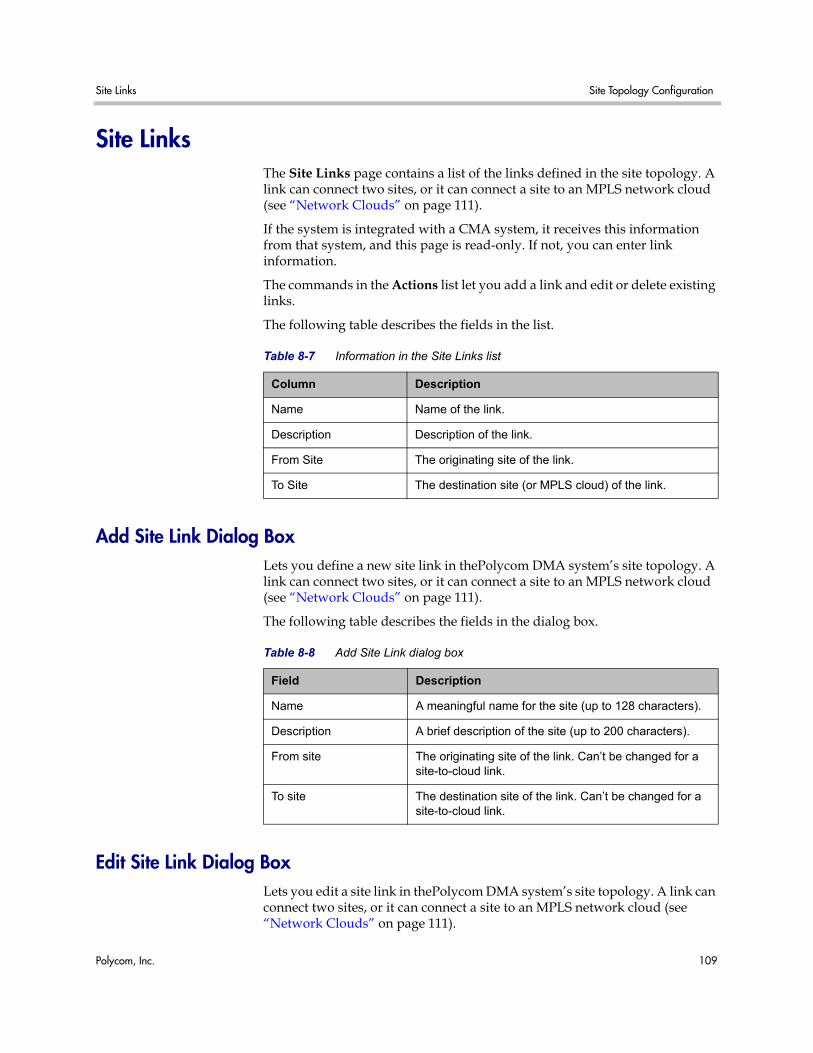
Site Links Site Topology Configuration
Polycom, Inc. 109
Site Links The Site Links page contains a list of the links defined in the site topology. A link can connect two sites, or it can connect a site to an MPLS network cloud (see “Network Clouds” on page 111).
If the system is integrated with a CMA system, it receives this information from that system, and this page is read-only. If not, you can enter link information.
The commands in the Actions list let you add a link and edit or delete existing links.
The following table describes the fields in the list.
Add Site Link Dialog Box Lets you define a new site link in thePolycom DMA system’s site topology. A link can connect two sites, or it can connect a site to an MPLS network cloud (see “Network Clouds” on page 111).
The following table describes the fields in the dialog box.
Edit Site Link Dialog Box Lets you edit a site link in thePolycom DMA system’s site topology. A link can connect two sites, or it can connect a site to an MPLS network cloud (see “Network Clouds” on page 111).
Table 8-7 Information in the Site Links list
Column Description
Name Name of the link.
Description Description of the link.
From Site The originating site of the link.
To Site The destination site (or MPLS cloud) of the link.
Table 8-8 Add Site Link dialog box
Field Description
Name A meaningful name for the site (up to 128 characters).
Description A brief description of the site (up to 200 characters).
From site The originating site of the link. Can’t be changed for a site-to-cloud link.
To site The destination site of the link. Can’t be changed for a site-to-cloud link.
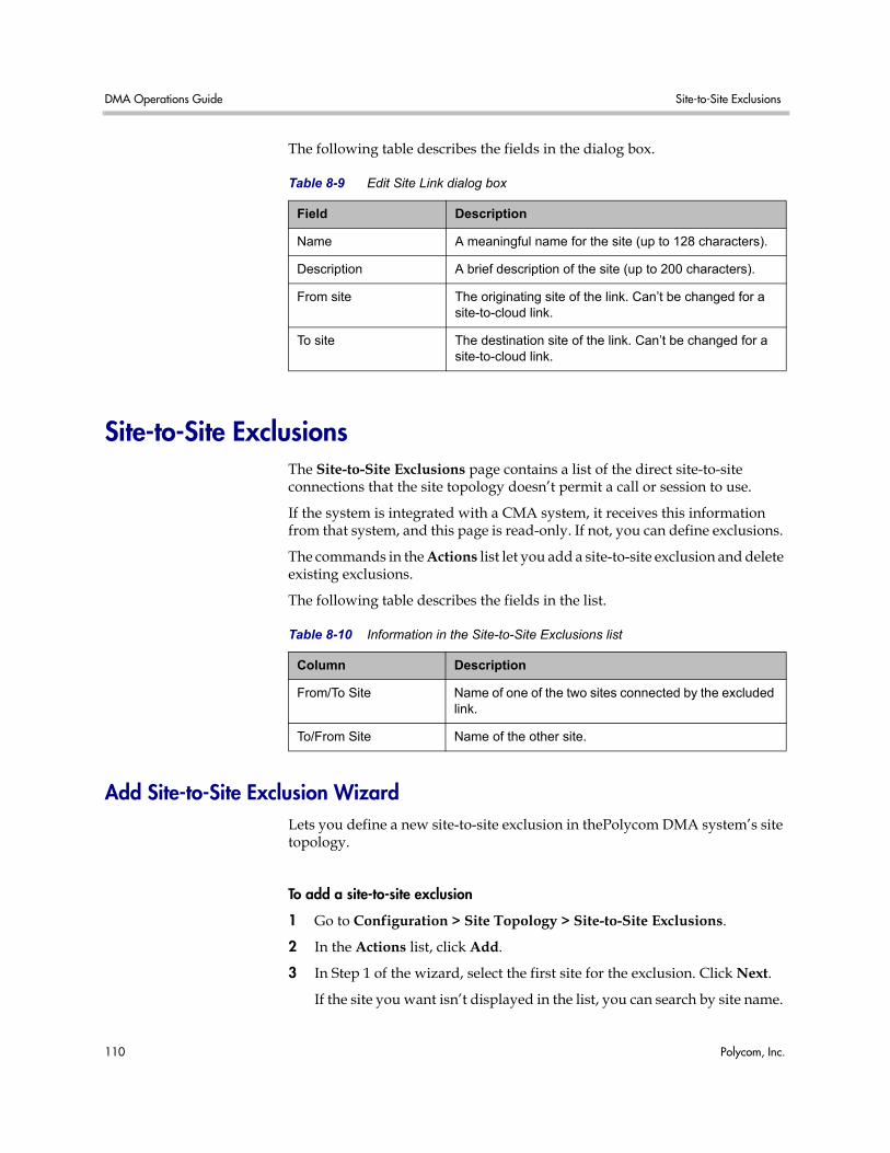
DMA Operations Guide Site-to-Site Exclusions
110 Polycom, Inc.
The following table describes the fields in the dialog box.
Site-to-Site Exclusions The Site-to-Site Exclusions page contains a list of the direct site-to-site connections that the site topology doesn’t permit a call or session to use.
If the system is integrated with a CMA system, it receives this information from that system, and this page is read-only. If not, you can define exclusions.
The commands in the Actions list let you add a site-to-site exclusion and delete existing exclusions.
The following table describes the fields in the list.
Add Site-to-Site Exclusion Wizard Lets you define a new site-to-site exclusion in thePolycom DMA system’s site topology.
To add a site-to-site exclusion
1 Go to Configuration > Site Topology > Site-to-Site Exclusions.
2 In the Actions list, click Add.
3 In Step 1 of the wizard, select the first site for the exclusion. Click Next.
If the site you want isn’t displayed in the list, you can search by site name.
Table 8-9 Edit Site Link dialog box
Field Description
Name A meaningful name for the site (up to 128 characters).
Description A brief description of the site (up to 200 characters).
From site The originating site of the link. Can’t be changed for a site-to-cloud link.
To site The destination site of the link. Can’t be changed for a site-to-cloud link.
Table 8-10 Information in the Site-to-Site Exclusions list
Column Description
From/To Site Name of one of the two sites connected by the excluded link.
To/From Site Name of the other site.
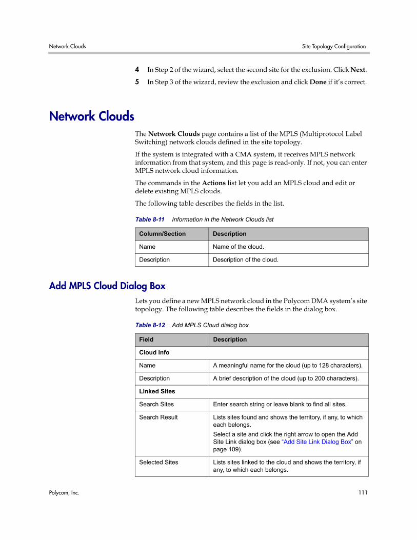
Network Clouds Site Topology Configuration
Polycom, Inc. 111
4 In Step 2 of the wizard, select the second site for the exclusion. Click Next.
5 In Step 3 of the wizard, review the exclusion and click Done if it’s correct.
Network Clouds The Network Clouds page contains a list of the MPLS (Multiprotocol Label Switching) network clouds defined in the site topology.
If the system is integrated with a CMA system, it receives MPLS network information from that system, and this page is read-only. If not, you can enter MPLS network cloud information.
The commands in the Actions list let you add an MPLS cloud and edit or delete existing MPLS clouds.
The following table describes the fields in the list.
Add MPLS Cloud Dialog Box Lets you define a new MPLS network cloud in the Polycom DMA system’s site topology. The following table describes the fields in the dialog box.
Table 8-11 Information in the Network Clouds list
Column/Section Description
Name Name of the cloud.
Description Description of the cloud.
Table 8-12 Add MPLS Cloud dialog box
Field Description
Cloud Info
Name A meaningful name for the cloud (up to 128 characters).
Description A brief description of the cloud (up to 200 characters).
Linked Sites
Search Sites Enter search string or leave blank to find all sites.
Search Result Lists sites found and shows the territory, if any, to which each belongs.
Select a site and click the right arrow to open the Add Site Link dialog box (see “Add Site Link Dialog Box” on page 109).
Selected Sites Lists sites linked to the cloud and shows the territory, if any, to which each belongs.
DMA Operations Guide Site Topology Configuration Procedures
112 Polycom, Inc.
Edit MPLS Cloud Dialog Box Lets you edit an MPLS network cloud in thePolycom DMA system’s site topology. The following table describes the fields in the dialog box.
Site Topology Configuration Procedures
To configure your site topology
1 Go to Configuration > Site Topology > Sites.
Initially, the list of sites contains only an entry named Internet/VPN, which can’t be edited.
2 For each site in your network topology, do the following:
a In the Actions list, click Add.
b In the Add Site dialog box, complete the General Info section. See “Add Site Dialog Box” on page 107.
c In the Subnets section, specify the subnet or subnets that make up the site. See “Add Subnet Dialog Box” on page 108.
d Click OK.
3 Go to Configuration > Site Topology > Site Links, and for each direct link between sites, do the following:
a In the Actions list, click Add.
b In the Add Site Link dialog box, define the link. See “Add Site Link Dialog Box” on page 109.
Table 8-13 Edit MPLS Cloud dialog box
Field Description
Cloud Info
Name A meaningful name for the cloud (up to 128 characters).
Description A brief description of the cloud (up to 200 characters).
Linked Sites
Search Sites Enter search string or leave blank to find all sites.
Search Result Lists sites found.
Select a site and click the right arrow to open the Add Site Link dialog box (see “Add Site Link Dialog Box” on page 109).
Selected Sites Lists sites linked to the cloud.
Site Topology Configuration Procedures Site Topology Configuration
Polycom, Inc. 113
c Click OK.
4 Go to Configuration > Site Topology > Network Clouds, and for each MPLS network cloud in your network topology, do the following:
a In the Actions list, click Add.
The Add MPLS Cloud dialog box appears.
b In the Cloud Info section, enter a name and description for the cloud.
c In the Linked Sites section, display the sites you defined. See “Add MPLS Cloud Dialog Box” on page 111.
d Select the first site linked to this cloud and click the arrow button to move it to the Linked Sites list.
The Add Site Link dialog box appears.
e Define the link. See “Add Site Link Dialog Box” on page 109.
f Repeat the previous two steps for each additional site linked to this cloud.
g Click OK.
5 Go to Configuration > Site Topology > Site-to-Site Exclusions, and for each exclusion in your network topology, do the following:
a In the Actions list, click Add.
b Complete the Add Site-to-Site Exclusions wizard. See “Add Site-to-Site Exclusion Wizard” on page 110.
Your site topology information is complete. For conferences with cascading enabled, the Polycom DMA system can use it to route calls to the nearest eligible MCU (based on zones and zone orders) that has available capacity and to create the cascade links between MCUs.
Note If in the future, you integrate this system with a Polycom CMA 5000 system, the site topology information from the Polycom CMA system will replace the information you entered.

DMA Operations Guide Site Topology Configuration Procedures
114 Polycom, Inc.
Polycom, Inc. 115
9Users and Groups
This chapter describes the following Polycom® Distributed Media Application™ (DMA™) 7000 system management topics related to users and groups:
• User Roles Overview
• Adding Users Overview
• Users
• Add User Dialog Box
• Edit User Dialog Box
• Conference Rooms Dialog Box
• Add Conference Room Dialog Box
• Edit Conference Room Dialog Box
• Users Procedures
• Conference Rooms Procedures
• Groups
• Import Enterprise Groups Dialog Box
• Edit Group Dialog Box
• Enterprise Groups Procedures
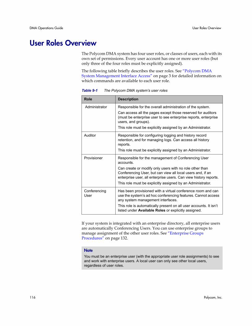
DMA Operations Guide User Roles Overview
116 Polycom, Inc.
User Roles Overview The Polycom DMA system has four user roles, or classes of users, each with its own set of permissions. Every user account has one or more user roles (but only three of the four roles must be explicitly assigned).
The following table briefly describes the user roles. See “Polycom DMA System Management Interface Access” on page 3 for detailed information on which commands are available to each user role.
If your system is integrated with an enterprise directory, all enterprise users are automatically Conferencing Users. You can use enterprise groups to manage assignment of the other user roles. See “Enterprise Groups Procedures” on page 132.
Table 9-1 The Polycom DMA system’s user roles
Role Description
Administrator Responsible for the overall administration of the system.
Can access all the pages except those reserved for auditors (must be enterprise user to see enterprise reports, enterprise users, and groups).
This role must be explicitly assigned by an Administrator.
Auditor Responsible for configuring logging and history record retention, and for managing logs. Can access all history reports.
This role must be explicitly assigned by an Administrator.
Provisioner Responsible for the management of Conferencing User accounts.
Can create or modify only users with no role other than Conferencing User, but can view all local users and, if an enterprise user, all enterprise users. Can view history reports.
This role must be explicitly assigned by an Administrator.
Conferencing User
Has been provisioned with a virtual conference room and can use the system’s ad hoc conferencing features. Cannot access any system management interfaces.
This role is automatically present on all user accounts. It isn’t listed under Available Roles or explicitly assigned.
Note You must be an enterprise user (with the appropriate user role assignments) to see and work with enterprise users. A local user can only see other local users, regardless of user roles.
Adding Users Overview Users and Groups
Polycom, Inc. 117
See also:
“Adding Users Overview” on page 117
“Users Procedures” on page 127
“Conference Rooms Procedures” on page 128
Adding Users Overview You can add users to the system in two ways:
• Add users manually to the Polycom DMA system. These are known as local users. When adding users manually, you must assign them conference rooms and any specific roles they should have.
• Integrate the Polycom DMA system with an enterprise directory (requires Administrator permissions). This integration allows users to log into the Polycom DMA system with their enterprise directory user names and passwords.
When a Polycom DMA system is integrated with an enterprise directory, the enterprise directory users are automatically added as Polycom DMA system users with a Conferencing User role and displayed in the Polycom DMA system Users list. An administrator can assign them additional roles as required.
A newly installed system has a single local user account, admin. We strongly recommend that, as part of initial system setup, you create a local user account for yourself with the Administrator role, log in using that account, and delete the admin user account. See the caution and first procedure in “Users Procedures” on page 127.
You can then create other local user accounts or integrate with an enterprise directory and assign additional roles to the appropriate enterprise users.
Integration with an enterprise directory is described in “Enterprise Directory” on page 87.
See also:
“Polycom® DMA™ System Initial Configuration Summary” on page 9
“User Roles Overview” on page 116
“Users Procedures” on page 127
“Conference Rooms Procedures” on page 128
Note You must be an enterprise user (with the appropriate user role assignments) to see and work with enterprise users. A local user can only see other local users, regardless of user roles.
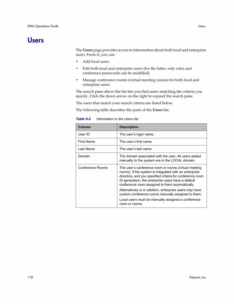
DMA Operations Guide Users
118 Polycom, Inc.
Users The Users page provides access to information about both local and enterprise users. From it, you can:
• Add local users.
• Edit both local and enterprise users (for the latter, only roles and conference passwords can be modified).
• Manage conference rooms (virtual meeting rooms) for both local and enterprise users.
The search pane above the list lets you find users matching the criteria you specify. Click the down arrow on the right to expand the search pane.
The users that match your search criteria are listed below.
The following table describes the parts of the Users list.
Table 9-2 Information in the Users list
Column Description
User ID The user’s login name.
First Name The user’s first name.
Last Name The user’s last name.
Domain The domain associated with the user. All users added manually to the system are in the LOCAL domain.
Conference Rooms The user’s conference room or rooms (virtual meeting rooms). If the system is integrated with an enterprise directory, and you specified criteria for conference room ID generation, the enterprise users have a default conference room assigned to them automatically.
Alternatively or in addition, enterprise users may have custom conference rooms manually assigned to them.
Local users must be manually assigned a conference room or rooms.
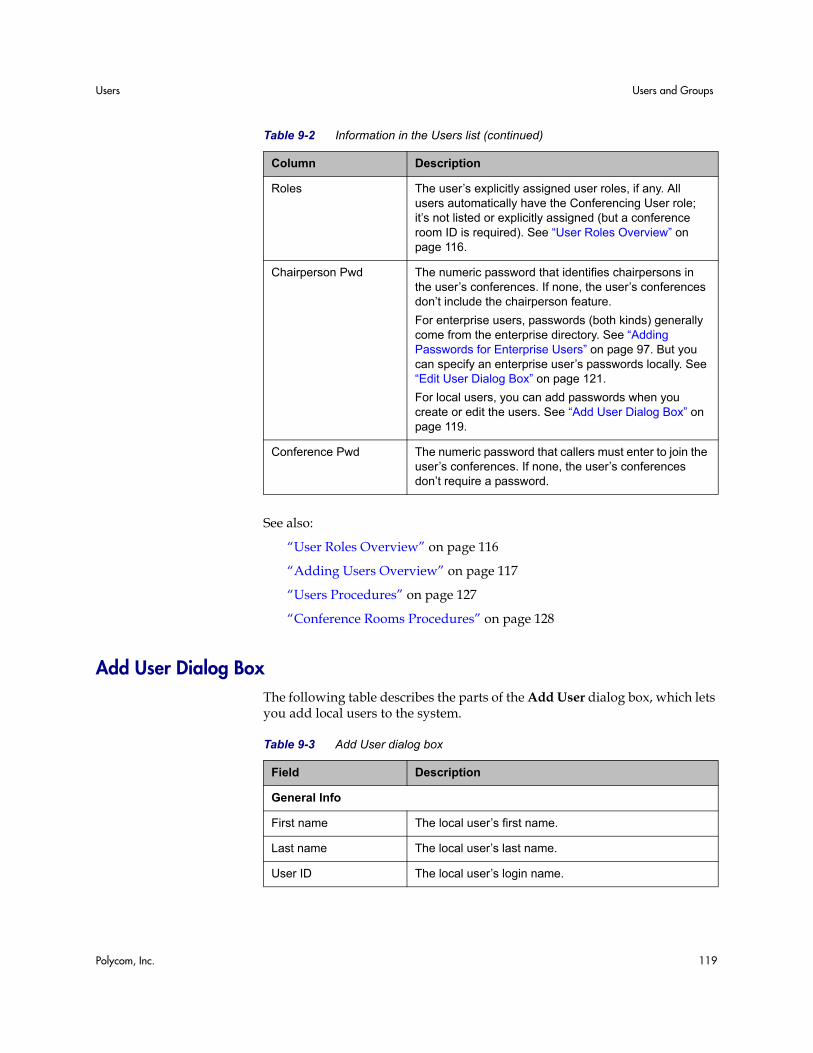
Users Users and Groups
Polycom, Inc. 119
See also:
“User Roles Overview” on page 116
“Adding Users Overview” on page 117
“Users Procedures” on page 127
“Conference Rooms Procedures” on page 128
Add User Dialog Box The following table describes the parts of the Add User dialog box, which lets you add local users to the system.
Roles The user’s explicitly assigned user roles, if any. All users automatically have the Conferencing User role; it’s not listed or explicitly assigned (but a conference room ID is required). See “User Roles Overview” on page 116.
Chairperson Pwd The numeric password that identifies chairpersons in the user’s conferences. If none, the user’s conferences don’t include the chairperson feature.
For enterprise users, passwords (both kinds) generally come from the enterprise directory. See “Adding Passwords for Enterprise Users” on page 97. But you can specify an enterprise user’s passwords locally. See “Edit User Dialog Box” on page 121.
For local users, you can add passwords when you create or edit the users. See “Add User Dialog Box” on page 119.
Conference Pwd The numeric password that callers must enter to join the user’s conferences. If none, the user’s conferences don’t require a password.
Table 9-2 Information in the Users list (continued)
Column Description
Table 9-3 Add User dialog box
Field Description
General Info
First name The local user’s first name.
Last name The local user’s last name.
User ID The local user’s login name.
DMA Operations Guide Users
120 Polycom, Inc.
Password The local user’s system login password (not conference or chairperson password).
Unless Allow any passwords is enabled (see “Security Configuration” on page 44), the system enforces the following password rules:
• Must contain at least seven characters.
• Must contain at least one lowercase character and one digit.
• Must not contain more than three consecutive instances of the same character.
• Can’t contain the user name or its reverse.
• Must have at least two differences from the previous password.
• Can’t be the same as one of the user’s previous three passwords.
• Passwords expire in 365 days.
Confirm password Retype the password to verify that you entered it correctly.
Account disabled If checked, user does not have conferencing privileges and can’t log into the system management interface.
Associated Roles
Available roles Lists the roles available for assignment to the user. All users automatically have the Conferencing User role; it’s not listed or explicitly assigned (but a conference room ID is required). See “User Roles Overview” on page 116.
Selected roles Lists the roles selected for assignment to the user.
Conference Passwords
Chairperson password The numeric password that identifies chairpersons in the user’s conferences. If none, the user’s conferences don’t include the chairperson feature.
Must contain numeric characters only (the digits 0-9) and may be up to 16 digits long. Can’t be the same as the conference password.
Conference password The numeric password that callers must enter to join the user’s conferences. If none, the user’s conferences don’t require a password.
Must contain numeric characters only (the digits 0-9) and may be up to 16 digits long. Can’t be the same as the chairperson password.
Table 9-3 Add User dialog box (continued)
Field Description
Users Users and Groups
Polycom, Inc. 121
See also:
“User Roles Overview” on page 116
“Adding Users Overview” on page 117
“Users Procedures” on page 127
“Conference Rooms Procedures” on page 128
Edit User Dialog Box The following table describes the parts of the Edit User dialog box. The General Info items are editable only for local (not enterprise) users.
Table 9-4 Edit User dialog box
Field Description
General Info
First name The user’s first name.
Last name The user’s last name.
User ID The user’s login name.
Password The user’s system login password (not conference or chairperson password). For enterprise users, passwords are maintained in the enterprise directory.
For local users, unless Allow any passwords is enabled (see “Security Configuration” on page 44), the system enforces the following password rules:
• Must contain at least seven characters.
• Must contain at least one lowercase character and one digit.
• Must not contain more than three consecutive instances of the same character.
• Can’t contain the user name or its reverse.
• Must have at least two differences from the previous password.
• Can’t be the same as one of the user’s previous three passwords.
• Passwords expire in 365 days.
Confirm password If changing password (local users only), retype the password to verify that you entered it correctly.
Account disabled If checked, user does not have conferencing privileges and can’t log into the system management interface.
DMA Operations Guide Users
122 Polycom, Inc.
Associated Roles
Available roles Lists the roles available for assignment to the user. All users automatically have the Conferencing User role; it’s not listed or explicitly assigned (but a conference room ID is required). See “User Roles Overview” on page 116.
Selected roles List the roles selected for assignment to the user.
Conference Passwords
Enterprise chairperson password
The numeric chairperson password generated from the Active Directory attribute specified for that purpose. If present (and if Override enterprise passwords is not checked), it can be entered to identify chairpersons in the user’s conferences.
If empty (and if Override enterprise passwords is not checked), the user’s conferences don’t include the chairperson feature.
See “Adding Passwords for Enterprise Users” on page 97.
Enterprise conference password
The numeric conference password generated from the Active Directory attribute specified for that purpose. If present (and if Override enterprise passwords is not checked), callers must enter this password to join the user’s conferences.
If empty (and if Override enterprise passwords is not checked), the user’s conferences don’t require a password.
See “Adding Passwords for Enterprise Users” on page 97.
Table 9-4 Edit User dialog box (continued)
Field Description
Users Users and Groups
Polycom, Inc. 123
See also:
“User Roles Overview” on page 116
“Adding Users Overview” on page 117
“Users Procedures” on page 127
“Conference Rooms Procedures” on page 128
Conference Rooms Dialog Box Lets you view, add, edit, and delete the selected user’s conference rooms. A user may have three kinds of conference rooms:
• One enterprise conference room (if this is an enterprise user) automatically assigned to the user as part of the enterprise directory integration process. You can’t delete this conference room, but you can modify it.
• Custom conference rooms manually added using the Add command in this dialog box.
Override enterprise passwords
If checked, the system ignores the enterprise passwords displayed above and uses the values specified below instead.
Chairperson password The numeric password that identifies chairpersons in the user’s conferences. Used if Override enterprise passwords is checked.
If empty (and if Override enterprise passwords is checked), the user’s conferences don’t include the chairperson feature.
Must contain numeric characters only (the digits 0-9) and may be up to 16 digits long. Can’t be the same as the conference password.
Conference password The numeric password that callers must enter to join the user’s conferences. If Override enterprise passwords is checked and this field is empty, the user’s conferences don’t require a password.
If empty (and if Override enterprise passwords is checked), the user’s conferences don’t require a password.
Must contain numeric characters only (the digits 0-9) and may be up to 16 digits long. Can’t be the same as the chairperson password.
Table 9-4 Edit User dialog box (continued)
Field Description
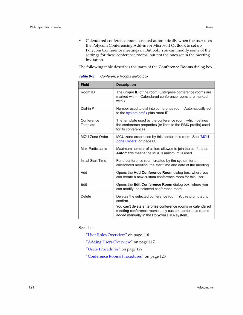
DMA Operations Guide Users
124 Polycom, Inc.
• Calendared conference rooms created automatically when the user uses the Polycom Conferencing Add-in for Microsoft Outlook to set up Polycom Conference meetings in Outlook. You can modify some of the settings for these conference rooms, but not the ones set in the meeting invitation.
The following table describes the parts of the Conference Rooms dialog box.
See also:
“User Roles Overview” on page 116
“Adding Users Overview” on page 117
“Users Procedures” on page 127
“Conference Rooms Procedures” on page 128
Table 9-5 Conference Rooms dialog box
Field Description
Room ID The unique ID of the room. Enterprise conference rooms are marked with ¤. Calendared conference rooms are marked with ».
Dial-in # Number used to dial into conference room. Automatically set to the system prefix plus room ID.
Conference Template
The template used by the conference room, which defines the conference properties (or links to the RMX profile) used for its conferences.
MCU Zone Order MCU zone order used by this conference room. See “MCU Zone Orders” on page 60.
Max Participants Maximum number of callers allowed to join the conference. Automatic means the MCU’s maximum is used.
Initial Start Time For a conference room created by the system for a calendared meeting, the start time and date of the meeting.
Add Opens the Add Conference Room dialog box, where you can create a new custom conference room for this user.
Edit Opens the Edit Conference Room dialog box, where you can modify the selected conference room.
Delete Deletes the selected conference room. You’re prompted to confirm.
You can’t delete enterprise conference rooms or calendared meeting conference rooms, only custom conference rooms added manually in the Polycom DMA system.
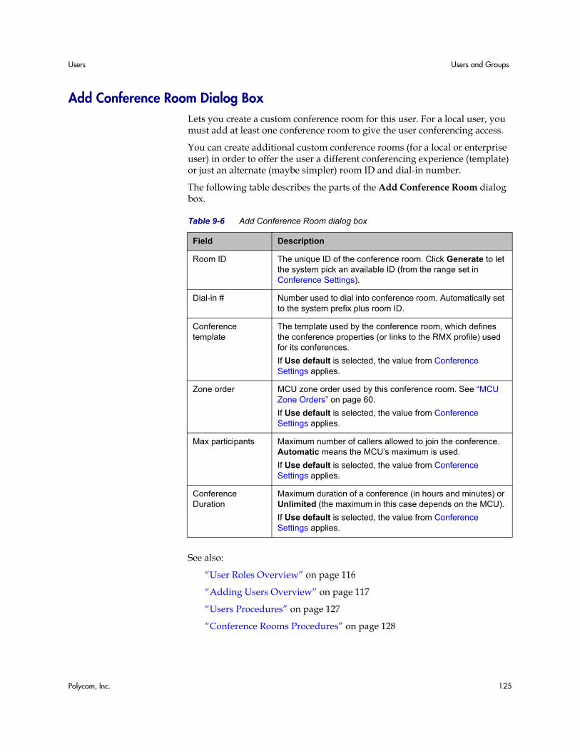
Users Users and Groups
Polycom, Inc. 125
Add Conference Room Dialog Box Lets you create a custom conference room for this user. For a local user, you must add at least one conference room to give the user conferencing access.
You can create additional custom conference rooms (for a local or enterprise user) in order to offer the user a different conferencing experience (template) or just an alternate (maybe simpler) room ID and dial-in number.
The following table describes the parts of the Add Conference Room dialog box.
See also:
“User Roles Overview” on page 116
“Adding Users Overview” on page 117
“Users Procedures” on page 127
“Conference Rooms Procedures” on page 128
Table 9-6 Add Conference Room dialog box
Field Description
Room ID The unique ID of the conference room. Click Generate to let the system pick an available ID (from the range set in Conference Settings).
Dial-in # Number used to dial into conference room. Automatically set to the system prefix plus room ID.
Conference template
The template used by the conference room, which defines the conference properties (or links to the RMX profile) used for its conferences.
If Use default is selected, the value from Conference Settings applies.
Zone order MCU zone order used by this conference room. See “MCU Zone Orders” on page 60.
If Use default is selected, the value from Conference Settings applies.
Max participants Maximum number of callers allowed to join the conference. Automatic means the MCU’s maximum is used.
If Use default is selected, the value from Conference Settings applies.
Conference Duration
Maximum duration of a conference (in hours and minutes) or Unlimited (the maximum in this case depends on the MCU).
If Use default is selected, the value from Conference Settings applies.
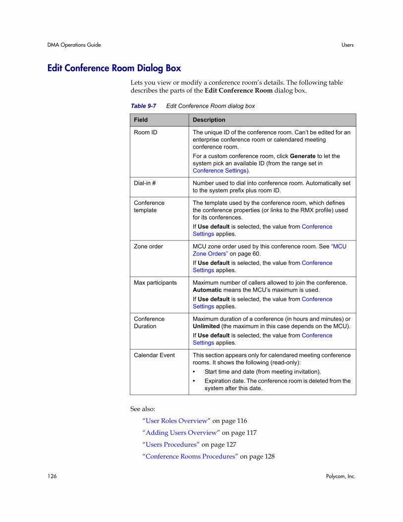
DMA Operations Guide Users
126 Polycom, Inc.
Edit Conference Room Dialog Box Lets you view or modify a conference room’s details. The following table describes the parts of the Edit Conference Room dialog box.
See also:
“User Roles Overview” on page 116
“Adding Users Overview” on page 117
“Users Procedures” on page 127
“Conference Rooms Procedures” on page 128
Table 9-7 Edit Conference Room dialog box
Field Description
Room ID The unique ID of the conference room. Can’t be edited for an enterprise conference room or calendared meeting conference room.
For a custom conference room, click Generate to let the system pick an available ID (from the range set in Conference Settings).
Dial-in # Number used to dial into conference room. Automatically set to the system prefix plus room ID.
Conference template
The template used by the conference room, which defines the conference properties (or links to the RMX profile) used for its conferences.
If Use default is selected, the value from Conference Settings applies.
Zone order MCU zone order used by this conference room. See “MCU Zone Orders” on page 60.
If Use default is selected, the value from Conference Settings applies.
Max participants Maximum number of callers allowed to join the conference. Automatic means the MCU’s maximum is used.
If Use default is selected, the value from Conference Settings applies.
Conference Duration
Maximum duration of a conference (in hours and minutes) or Unlimited (the maximum in this case depends on the MCU).
If Use default is selected, the value from Conference Settings applies.
Calendar Event This section appears only for calendared meeting conference rooms. It shows the following (read-only):
• Start time and date (from meeting invitation).
• Expiration date. The conference room is deleted from the system after this date.
Users Users and Groups
Polycom, Inc. 127
Users Procedures
To remove the default admin account and create a local account for yourself with administrative privileges
1 Log in as admin and go to Operations > Users.
The Users page appears.
2 Create a local user account for yourself with the Administrator role. See “To add a local user” on page 127.
3 Log out and log back in using your new local account.
4 Go to Operations > Users and delete the admin account. See “To delete a local user” on page 128.
To find a user or users
1 Go to Operations > Users.
The Users page appears.
2 For a simple search, enter a search string in the Search users field and press ENTER.
The system matches the string you enter against the beginning of the user ID, first name, and last name. If you enter “sa” it displays users whose IDs or first or last names begin with “sa.” To search for a string not at the beginning of the field, you can use an asterisk (*) as a wildcard. You can restrict the search to local users by selecting the check box.
3 For more search options, click the down arrow to the right.
Additional controls appear that let you search specific fields and use specific filters.
4 Select the filters you want, enter search strings for one or more fields, and click Search.
The system displays the users matching your search criteria.
To add a local user
1 Go to Operations > Users.
2 In the Actions list, click Add.
3 In the Add User dialog box, complete the General Info fields. See “Add User Dialog Box” on page 119.
Caution To eliminate a serious security risk, perform the first procedure below as soon as possible after installing your system.
DMA Operations Guide Users
128 Polycom, Inc.
4 To assign the user additional roles (besides Conferencing User), click Roles. Select the role or roles you want to assign and use the arrow button to move them to the Selected Roles list.
5 Click OK.
To edit a user
1 Go to Operations > Users.
2 If necessary, filter the Users list to find the user to be modified.
3 Select the user and click Edit.
4 As required, edit the General Info, Roles, and Conference Passwords sections of the User Properties dialog box. See “Edit User Dialog Box” on page 121.
For enterprise users, you can change their roles and their chairperson and conference passwords, and you can enable or disable their accounts, but you can’t change user names, user IDs, or user passwords. For local users, you can change everything but the user ID.
5 Click OK.
To delete a local user
1 Go to Operations > Users.
2 If necessary, filter the Users list to find the user to be deleted.
You can only delete local users, not users added from the enterprise directory.
3 Select the user and click Delete User.
4 In the Delete User dialog box, click Yes.
The user is deleted from the Polycom DMA system.
See also:
“User Roles Overview” on page 116
“Adding Users Overview” on page 117
Conference Rooms Procedures
To add a conference room to a user
1 Go to Operations > Users and select the user to whom you want to add a room.
Users Users and Groups
Polycom, Inc. 129
2 In the Actions list, click Manage Conf Rooms.
The Conference Rooms dialog box appears.
3 Click Add.
The Add Conference Room dialog box appears.
4 Complete the settings for the new conference room. See “Add Conference Room Dialog Box” on page 125.
5 Click OK.
To edit one of a user’s conference rooms
1 Go to Operations > Users and select the user whose conference room you want to edit.
2 In the Actions list, click Manage Conf Rooms.
The Conference Rooms dialog box appears.
3 Select the conference room you want to edit and click Edit.
The Edit Conference Room dialog box appears.
4 Modify the settings you want to change. See “Edit Conference Room Dialog Box” on page 126.
5 Click OK.
To delete one of a user’s custom conference rooms
1 Go to Operations > Users and select the user whose custom conference room you want to delete.
2 In the Actions list, click Manage Conf Rooms.
The Conference Rooms dialog box appears.
3 Select the conference room you want to remove and click Delete.
You can’t delete an enterprise conference room or a conference room created by the system for a calendared meeting.
4 When prompted to confirm, click Yes.
See also:
“User Roles Overview” on page 116
“Adding Users Overview” on page 117
“Users Procedures” on page 127
DMA Operations Guide Groups
130 Polycom, Inc.
Groups Groups functionality is available only if your Polycom DMA system is integrated with an enterprise directory. User groups are defined in your enterprise directory and imported into the Polycom DMA system from there.
The Groups page provides access to information about enterprise groups. From it, you can:
• Import enterprise groups.
• Specify Polycom DMA system roles to be assigned to members of a group.
• Specify a conference template and MCU zone order to be used for a group.
The following table describes the fields on the Groups page.
See also:
“Import Enterprise Groups Dialog Box” on page 131
“Edit Group Dialog Box” on page 131
“Enterprise Groups Procedures” on page 132
Note • You must be an enterprise user (with the appropriate user role assignments) to
see and work with enterprise users. A local user can only see other local users, regardless of user roles.
• Microsoft Active Directory provides two group types and four group scopes. The Polycom DMA system supports only security groups (not distribution groups) with universal or global scope.
Table 9-8 Fields on the Groups page
Field Description
Group Name Name of the group, as defined in the enterprise directory.
Description Description from the enterprise directory.
Domain Name of the domain to which the group belongs.
Conference Template Template assigned to the group, if any. See “Conference Templates” on page 65.
MCU Zone Order MCU zone order assigned to this group, if any. See “MCU Zone Orders” on page 60.
Assigned Roles DMA system roles, if any, that are automatically assigned to members of this group (all users automatically have the Conferencing User role; it’s not listed or explicitly assigned). See “User Roles Overview” on page 116.
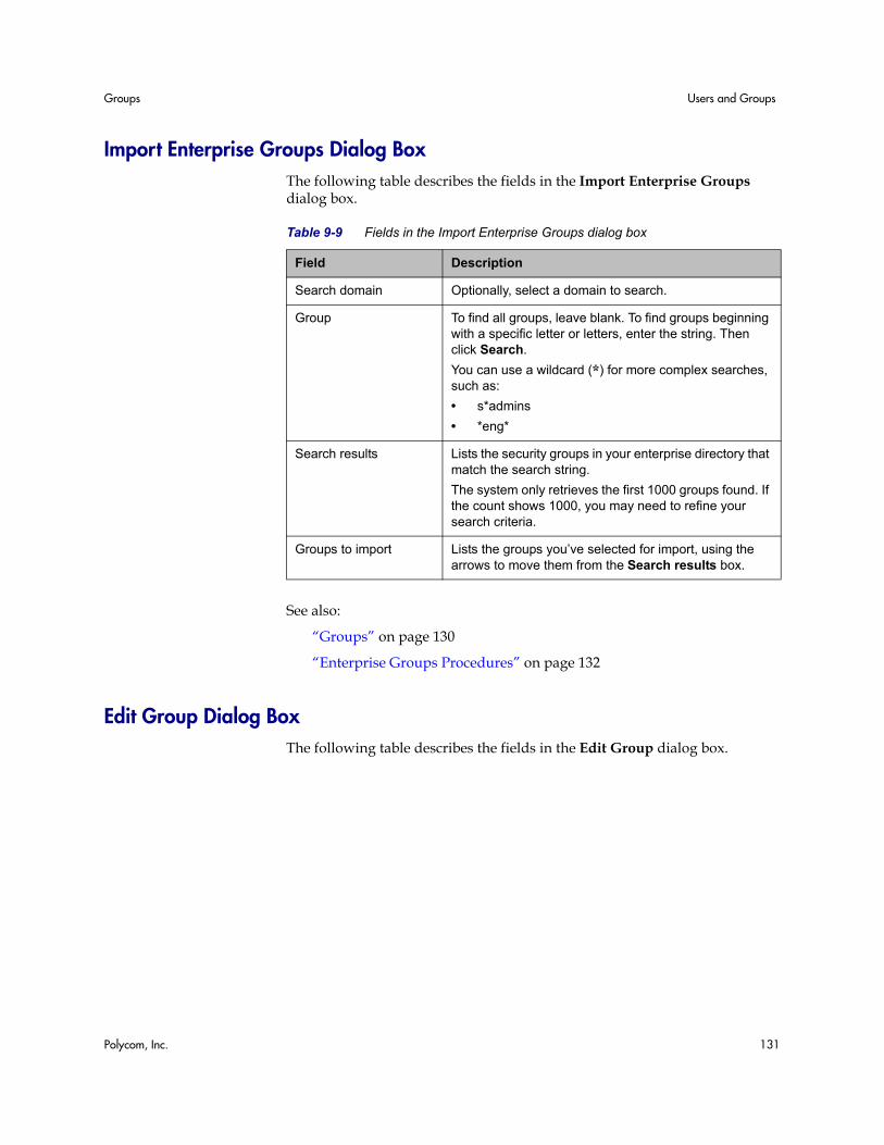
Groups Users and Groups
Polycom, Inc. 131
Import Enterprise Groups Dialog Box The following table describes the fields in the Import Enterprise Groups dialog box.
See also:
“Groups” on page 130
“Enterprise Groups Procedures” on page 132
Edit Group Dialog Box The following table describes the fields in the Edit Group dialog box.
Table 9-9 Fields in the Import Enterprise Groups dialog box
Field Description
Search domain Optionally, select a domain to search.
Group To find all groups, leave blank. To find groups beginning with a specific letter or letters, enter the string. Then click Search.
You can use a wildcard (*) for more complex searches, such as:
• s*admins
• *eng*
Search results Lists the security groups in your enterprise directory that match the search string.
The system only retrieves the first 1000 groups found. If the count shows 1000, you may need to refine your search criteria.
Groups to import Lists the groups you’ve selected for import, using the arrows to move them from the Search results box.
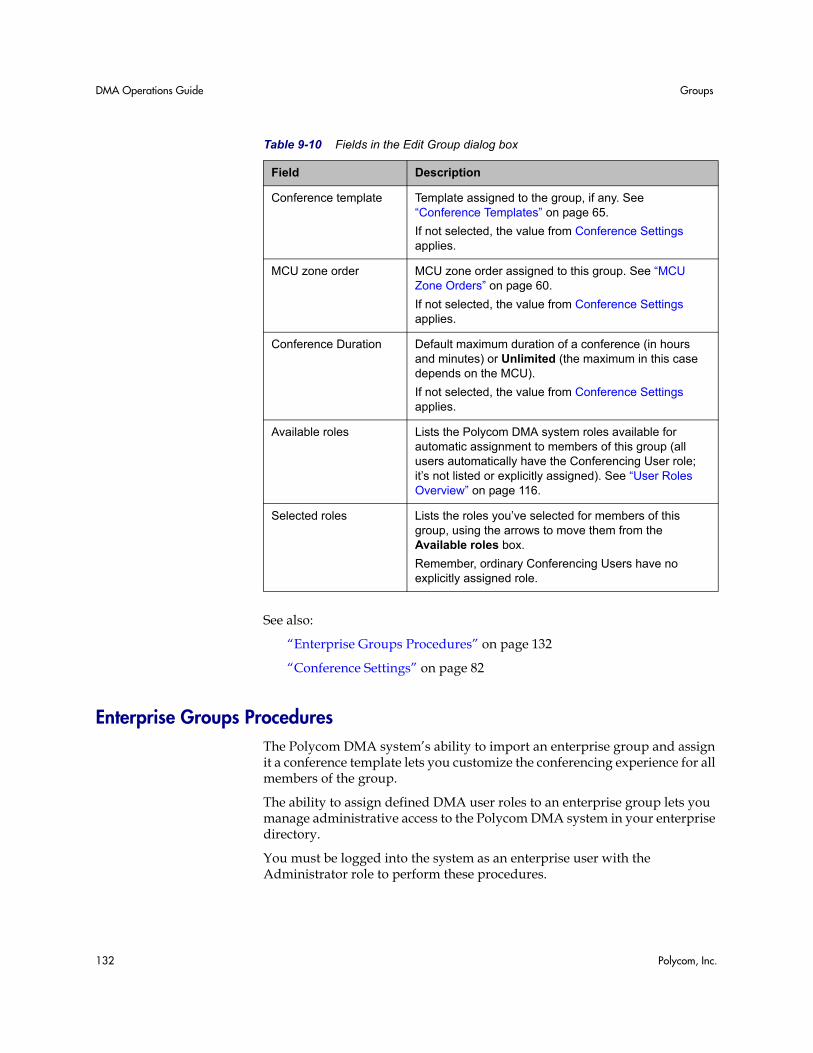
DMA Operations Guide Groups
132 Polycom, Inc.
See also:
“Enterprise Groups Procedures” on page 132
“Conference Settings” on page 82
Enterprise Groups Procedures The Polycom DMA system’s ability to import an enterprise group and assign it a conference template lets you customize the conferencing experience for all members of the group.
The ability to assign defined DMA user roles to an enterprise group lets you manage administrative access to the Polycom DMA system in your enterprise directory.
You must be logged into the system as an enterprise user with the Administrator role to perform these procedures.
Table 9-10 Fields in the Edit Group dialog box
Field Description
Conference template Template assigned to the group, if any. See “Conference Templates” on page 65.
If not selected, the value from Conference Settings applies.
MCU zone order MCU zone order assigned to this group. See “MCU Zone Orders” on page 60.
If not selected, the value from Conference Settings applies.
Conference Duration Default maximum duration of a conference (in hours and minutes) or Unlimited (the maximum in this case depends on the MCU).
If not selected, the value from Conference Settings applies.
Available roles Lists the Polycom DMA system roles available for automatic assignment to members of this group (all users automatically have the Conferencing User role; it’s not listed or explicitly assigned). See “User Roles Overview” on page 116.
Selected roles Lists the roles you’ve selected for members of this group, using the arrows to move them from the Available roles box.
Remember, ordinary Conferencing Users have no explicitly assigned role.
Groups Users and Groups
Polycom, Inc. 133
To set up an enterprise group for Polycom DMA management and operations users
1 In your enterprise directory, create a security group containing the users to whom you want to give access to the Polycom DMA system’s management and operations interface.
It’s up to you whether you want to assign all the user roles to a single group or create separate groups for each user role.
2 On the Polycom DMA system, go to Operations > Groups.
3 In the Actions list, click Import Enterprise Groups.
4 In the Import Enterprise Groups dialog box, use Search to find the system administration group you created. Then move it to the Groups to import box and click OK. See “Import Enterprise Groups Dialog Box” on page 131.
5 On the Groups page, select your new group and, in the Actions list, click Edit.
6 In the Edit Group dialog box, move the user roles you want to give members of this group to the Selected roles box. See “Edit Group Dialog Box” on page 131.
7 Click OK.
All members of this group will now share the system access privileges you assigned to the group.
8 To grant Polycom DMA system access privileges to a user or remove those privileges, just add or remove the user from the appropriate enterprise group.
To specify which MCUs a group uses by assigning an MCU Zone Order
1 If necessary, create the MCU zone and the zone order needed. See “MCU Zone Procedures” on page 59 and “MCU Zone Order Procedures” on page 63.
2 Go to Operations > Groups, select the group to which you need to assign a zone order, and in the Actions list, click Edit.
3 In the Edit Group dialog box’s MCU zone order list, select the zone order to be used for this group. See “Edit Group Dialog Box” on page 131.
4 Click OK.
To set up a custom conferencing experience for an enterprise group
1 Go to Configuration > Conference Setup > Conference Templates and create a template that defines the conferencing experience for this group. See “Conference Templates Procedures” on page 80.
DMA Operations Guide Groups
134 Polycom, Inc.
2 Optionally, in the Actions list, click Move Up until your new conference template has Priority 1.
This ensures that users who have access to multiple conference templates will use this one for their enterprise conference room. You can choose a different priority level, but then some members of the group for which you created the template may end up using a higher-ranking template.
3 Go to Operations > Groups, select the group for which you created the template, and in the Actions list, click Edit.
4 In the Edit Group dialog box’s Conference template list, select the template you created for this group. See “Edit Group Dialog Box” on page 131.
5 Click OK.
Polycom, Inc. 135
10System Operations
This chapter describes the following Polycom® Distributed Media Application™ (DMA™) 7000 system operations topics:
• Management and Maintenance Overview
• Recommended Regular Maintenance
• Dashboard
• Monitoring Login Sessions
• Tools
• System Log Files
• Backing Up and Restoring
• Upgrading the Software
• Adding a Second Server
• Replacing a Failed Server
• Shutting Down and Restarting
Management and Maintenance Overview The Polycom DMA system requires relatively little ongoing maintenance beyond monitoring the status of the system and downloading backups and other data you want to archive. All system management and maintenance tasks can be performed in the management interface.
Administrator Responsibilities As a Polycom DMA system administrator, you’re responsible for the installation and ongoing maintenance of the system. You should be familiar with the following configurations, tasks, and operations:
• Installing licenses when the system is first installed and when additional MCUs are added. See “License and Capabilities” on page 20.
DMA Operations Guide Management and Maintenance Overview
136 Polycom, Inc.
• Monitoring system health and performing the recommended regular maintenance. See “Recommended Regular Maintenance” on page 137.
• Using the system tools provided to aid with system and network diagnostics, monitoring, and troubleshooting. See “Tools” on page 145. Should the need arise, Polycom Global Services personnel may ask you to run these tools.
• Upgrading the system when upgrades/patches are made available. See “Upgrading the Software” on page 153.
Administrative Best Practices The following are some of our recommendations for administrative best practices:
• Perform the recommended regular maintenance.
• Except in emergencies or when instructed to by Polycom Global Services personnel, don’t reconfigure, install an upgrade, or restore a backup when there are active calls and conferences on the system. Many of these operations will require a system restart to complete, which will result in these calls and conferences being dropped. Before performing these operations, busy out all MCUs and wait for all conferencing activity to cease.
• Before you reconfigure, install an upgrade, or restore a backup, manually create a new backup. Then download and archive this backup in the event that something unforeseen occurs and it becomes necessary to restore the system to a known good state.
• For proper name resolution and smooth network operations, configure at least one DNS server in your network configuration (see “Network” on page 17), and preferably two or more. This allows the Polycom DMA system to function properly in the event of a single external DNS failure.
• Configure at least one NTP server in your time configuration (see “System Time” on page 19) and preferably two or more. Proper time management helps ensure that your cluster operates efficiently and helps in diagnosing any issues that may arise in the future. Proper system time is also essential for accurate audit and CDR data.
• Unless otherwise instructed by Polycom Global Services or to change the default root password after installation, always use the Maximum Security setting. See “Security Configuration” on page 44.
Auditor Responsibilities As a Polycom DMA system auditor, you’re responsible for managing the system’s logging and history retention. You should be familiar with the following configurations and operations:
Recommended Regular Maintenance System Operations
Polycom, Inc. 137
• Configuring logging for the system. See “Logging Configuration” on page 23. These settings affect the number and the contents of the log archives available for download from the system. See “System Log Files” on page 147. Polycom Global Services personnel may ask you to adjust the logging configuration and/or download and send them logs.
• Configuring history retention levels for the system. See “History Record Retention” on page 24. These settings affect how much system activity history is retained on the system and available for download as CDRs. See “Call History Report” on page 163, “Conference History Report” on page 165, and “Export CDR Data” on page 167.
Auditor Best Practices The following are some of our recommendations for auditing best practices:
• Unless otherwise instructed by Polycom Global Services, configure logging at the production level with a rolling frequency of every day and a retention period of 60 days. If hard drive space becomes an issue, decrease the retention period incrementally until the disk space issue is resolved.
• Download log archives regularly and back them up securely (preferably offsite as well as onsite).
• Export CDRs regularly and back them up securely (preferably offsite as well as onsite).
Recommended Regular Maintenance Perform the following tasks to keep your Polycom DMA system operating trouble-free and at peak efficiency. These tasks can be done quickly and should be run at least weekly.
Regular archive of backups
Log into the Polycom DMA system, go to Operations > Backup and Restore, and check for new backups. If there are new backups, download and archive the latest one.
Every night, the Polycom DMA system determines whether its configuration or database data have changed since the last time it performed a backup. If so, it creates a new backup instance. For details on backups, see “Backing Up and Restoring” on page 149.
General system health and capacity checks
On the Dashboard (see “Dashboard” on page 140), verify that no alerts are visible and that:
DMA Operations Guide Recommended Regular Maintenance
138 Polycom, Inc.
• The system didn’t run out of capacity at any point in time. If the Capacity Usage History graph shows spikes at or near the system’s maximum capacity, it may be time to add more.
• All the expected MCUs are connected, in service, and have the expected capacities. If there appear to be issues with an MCU, check its configuration and status, and if necessary, call Polycom Global Services. See “Device Management” on page 51.
• The H.323 Signaling Status section indicates the status of the gatekeeper connection is OK, and that the network latency between the system and gatekeeper is within the range you would expect for your network (it may be helpful to keep latency records for comparison over time). If it isn’t, contact your network administrator or Polycom Global Services.
• The Network Status section shows the correct number of cluster members (1 or 2), one of which is the active web host, and indicates that the network interface(s) for the node(s) are in a good state (upward green arrow) and have the expected speeds:
— For Private, 1000 Mbps / Full. Not applicable to a single-node system. In a two-node system, errors on the private link may indicate a problem with the system. Check the crossover cable connecting the two servers. If necessary, shut down both servers, replace the crossover cable, and restart the servers. If that doesn’t solve the problem, contact Polycom Global Services.
— For Public, the speed you expect for your enterprise network. Errors on the enterprise link may indicate an error in the interface between the Polycom DMA system and your enterprise network. Contact your network administrator to resolve the issue.
• The System Information section shows information for one or two nodes, depending on your system configuration. Verify that:
— The disk space usage for each node is less than 90% and Total memory is greater than Free memory by at least 500 MB. If either is not true, contact Polycom Global Services. If disk usage is too high, reduce the number of days to retain log archives. See “Logging Configuration” on page 23.
— The time for each cluster node is correct and within a few seconds of the other. If not, check your time configuration and NTP servers. See “System Time” on page 19.
Enterprise directory health
If the Polycom DMA system is integrated with an enterprise directory, check the following (you must be logged in as an enterprise user):
• Reports > Enterprise Directory Integration (see “Enterprise Directory Integration Report” on page 169). Check the status and results of the last cache update, and verify that membership information for imported groups, if any, was successfully loaded.
Recommended Regular Maintenance System Operations
Polycom, Inc. 139
• Reports > Conference Room Errors (see “Conference Room Errors Report” on page 173). Check:
— The total number of users and the number of users with conference room IDs. Make sure both are about what you would expect for your system (it may be helpful to keep records for comparison over time). Contact your enterprise directory administrator if necessary.
— The number of users with blank, invalid, or duplicate conference room IDs. These are enterprise users not properly provisioned for conferencing on the Polycom DMA system. They’re listed below. Contact your enterprise directory administrator to resolve issues with these users.
• Reports > Orphaned Groups and Users (see “Orphaned Groups and Users Report” on page 171). Verify that the number of orphans is not unexpectedly large.
• Reports > Enterprise Password (see “Enterprise Password Errors Report” on page 175). If you’re assigning conference and/or chairperson passwords to enterprise users, verify that the number of password errors is not unexpectedly large.
Security configuration
Go to Configuration > System > Security Configuration and verify that the security settings are what you expect (we strongly recommend always using the maximum security mode). Any departure from the settings you expected to see may indicate that your system has been compromised. See “Security Configuration” on page 44.
Certificates
Go to Configuration > System > Certificate Management and verify that the list of certificates contains the certificates you’ve installed and looks as you would expect (an archived screen capture may be helpful for comparison).
Display the details for any certificate you’ve installed and verify they are as expected (again, an archived screen capture may be helpful for comparison).
CDR export
If you want to preserve detailed call and conference history data in spreadsheet form off the Polycom DMA system, periodically download the system’s CDR (call detail record) data to your PC. See “Export CDR Data” on page 167.
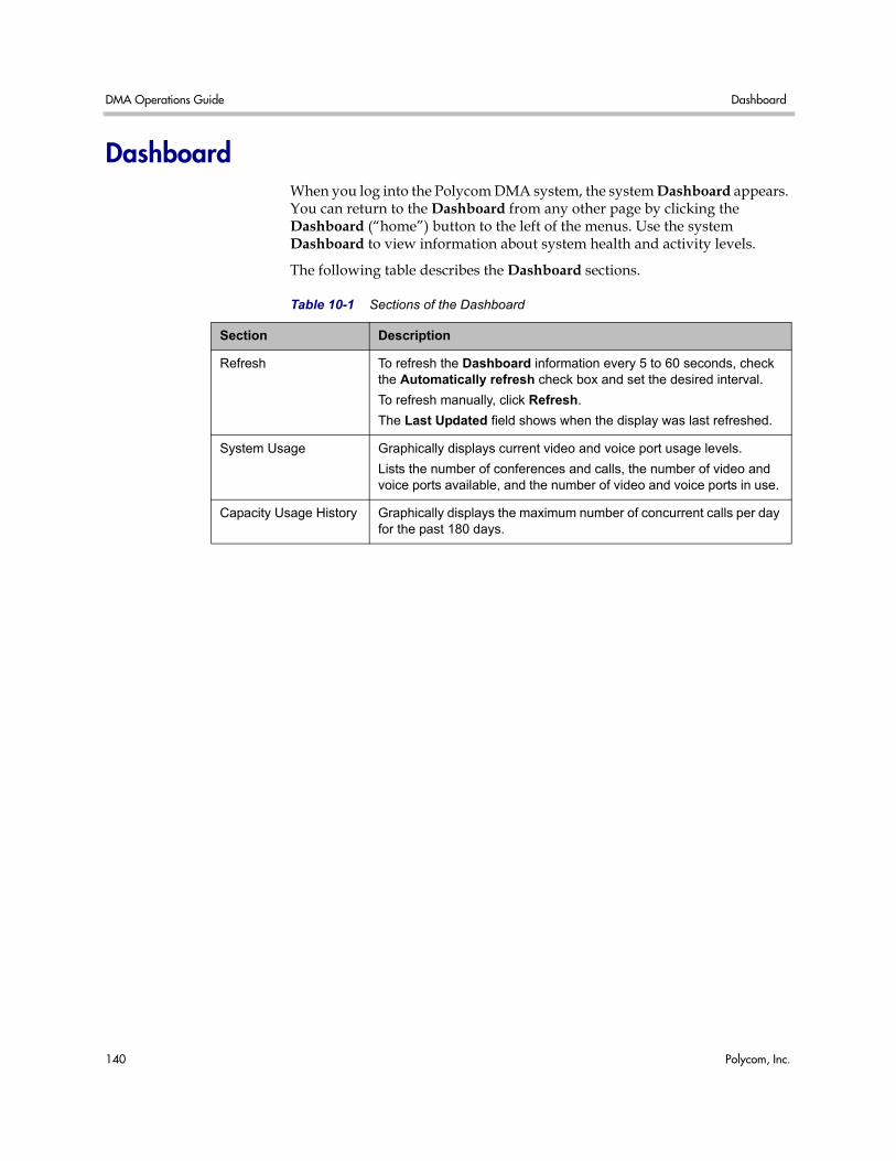
DMA Operations Guide Dashboard
140 Polycom, Inc.
Dashboard When you log into the Polycom DMA system, the system Dashboard appears. You can return to the Dashboard from any other page by clicking the Dashboard (“home”) button to the left of the menus. Use the system Dashboard to view information about system health and activity levels.
The following table describes the Dashboard sections.
Table 10-1 Sections of the Dashboard
Section Description
Refresh To refresh the Dashboard information every 5 to 60 seconds, check the Automatically refresh check box and set the desired interval.
To refresh manually, click Refresh.
The Last Updated field shows when the display was last refreshed.
System Usage Graphically displays current video and voice port usage levels.
Lists the number of conferences and calls, the number of video and voice ports available, and the number of video and voice ports in use.
Capacity Usage History Graphically displays the maximum number of concurrent calls per day for the past 180 days.
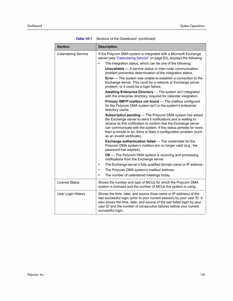
Dashboard System Operations
Polycom, Inc. 141
Calendaring Service If the Polycom DMA system is integrated with a Microsoft Exchange server (see “Calendaring Service” on page 83), displays the following:
• The integration status, which can be one of the following:
Unavailable — A service status or inter-node communication problem prevented determination of the integration status.
Error — The system was unable to establish a connection to the Exchange server. This could be a network or Exchange server problem, or it could be a login failure.
Awaiting Enterprise Directory — The system isn’t integrated with the enterprise directory, required for calendar integration.
Primary SMTP mailbox not found — The mailbox configured for the Polycom DMA system isn’t in the system’s enterprise directory cache.
Subscription pending — The Polycom DMA system has asked the Exchange server to send it notifications and is waiting to receive its first notification to confirm that the Exchange server can communicate with the system. If this status persists for more than a minute or so, there is likely a configuration problem (such as an invalid certificate).
Exchange authentication failed — The credentials for the Polycom DMA system’s mailbox are no longer valid (e.g., the password has expired).
OK — The Polycom DMA system is receiving and processing notifications from the Exchange server.
• The Exchange server’s fully qualified domain name or IP address.
• The Polycom DMA system’s mailbox address.
• The number of calendared meetings today.
License Status Shows the number and type of MCUs for which the Polycom DMA system is licensed and the number of MCUs the system is using.
User Login History Shows the time, date, and source (host name or IP address) of the last successful login (prior to your current session) by your user ID. It also shows the time, date, and source of the last failed login by your user ID and the number of consecutive failures before your current successful login.
Table 10-1 Sections of the Dashboard (continued)
Section Description
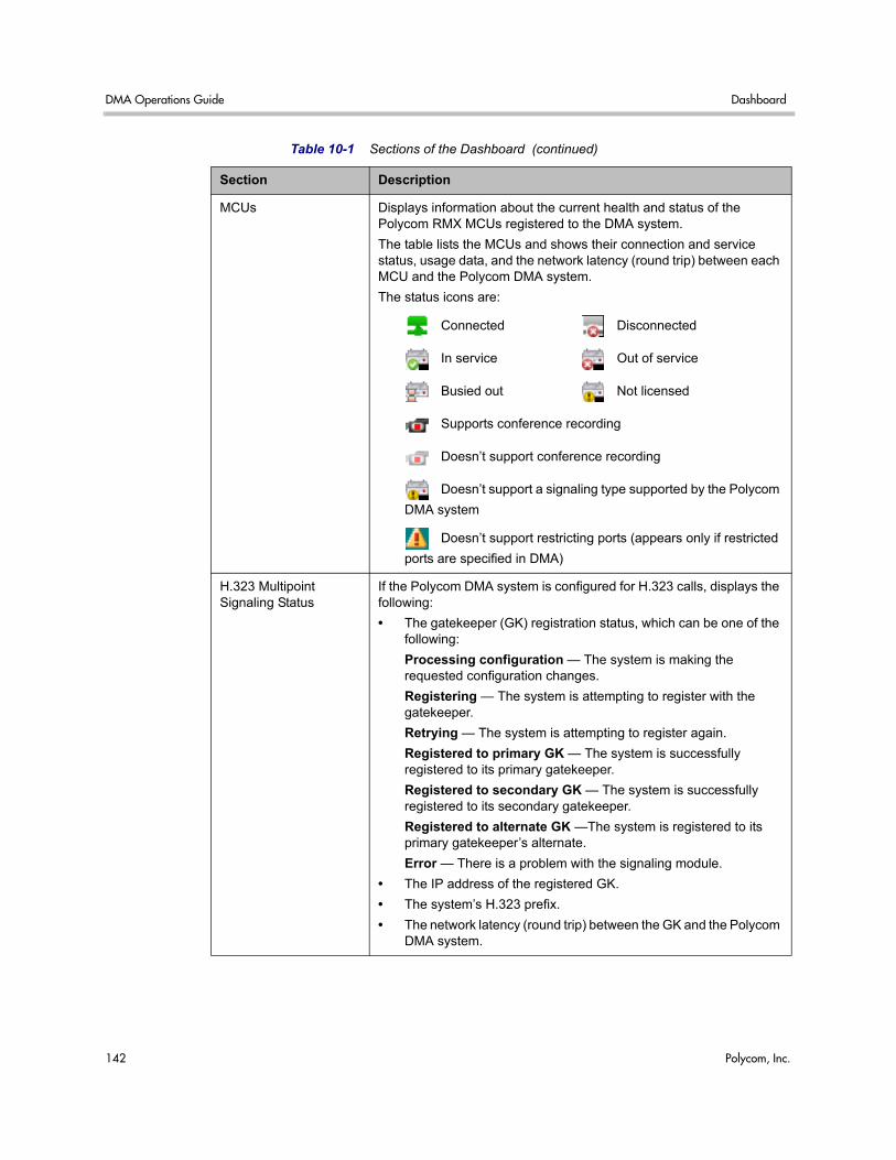
DMA Operations Guide Dashboard
142 Polycom, Inc.
MCUs Displays information about the current health and status of the Polycom RMX MCUs registered to the DMA system.
The table lists the MCUs and shows their connection and service status, usage data, and the network latency (round trip) between each MCU and the Polycom DMA system.
The status icons are:
Connected Disconnected
In service Out of service
Busied out Not licensed
Supports conference recording
Doesn’t support conference recording
Doesn’t support a signaling type supported by the Polycom
DMA system
Doesn’t support restricting ports (appears only if restricted
ports are specified in DMA)
H.323 Multipoint Signaling Status
If the Polycom DMA system is configured for H.323 calls, displays the following:
• The gatekeeper (GK) registration status, which can be one of the following:
Processing configuration — The system is making the requested configuration changes.
Registering — The system is attempting to register with the gatekeeper.
Retrying — The system is attempting to register again.
Registered to primary GK — The system is successfully registered to its primary gatekeeper.
Registered to secondary GK — The system is successfully registered to its secondary gatekeeper.
Registered to alternate GK —The system is registered to its primary gatekeeper’s alternate.
Error — There is a problem with the signaling module.
• The IP address of the registered GK.
• The system’s H.323 prefix.
• The network latency (round trip) between the GK and the Polycom DMA system.
Table 10-1 Sections of the Dashboard (continued)
Section Description
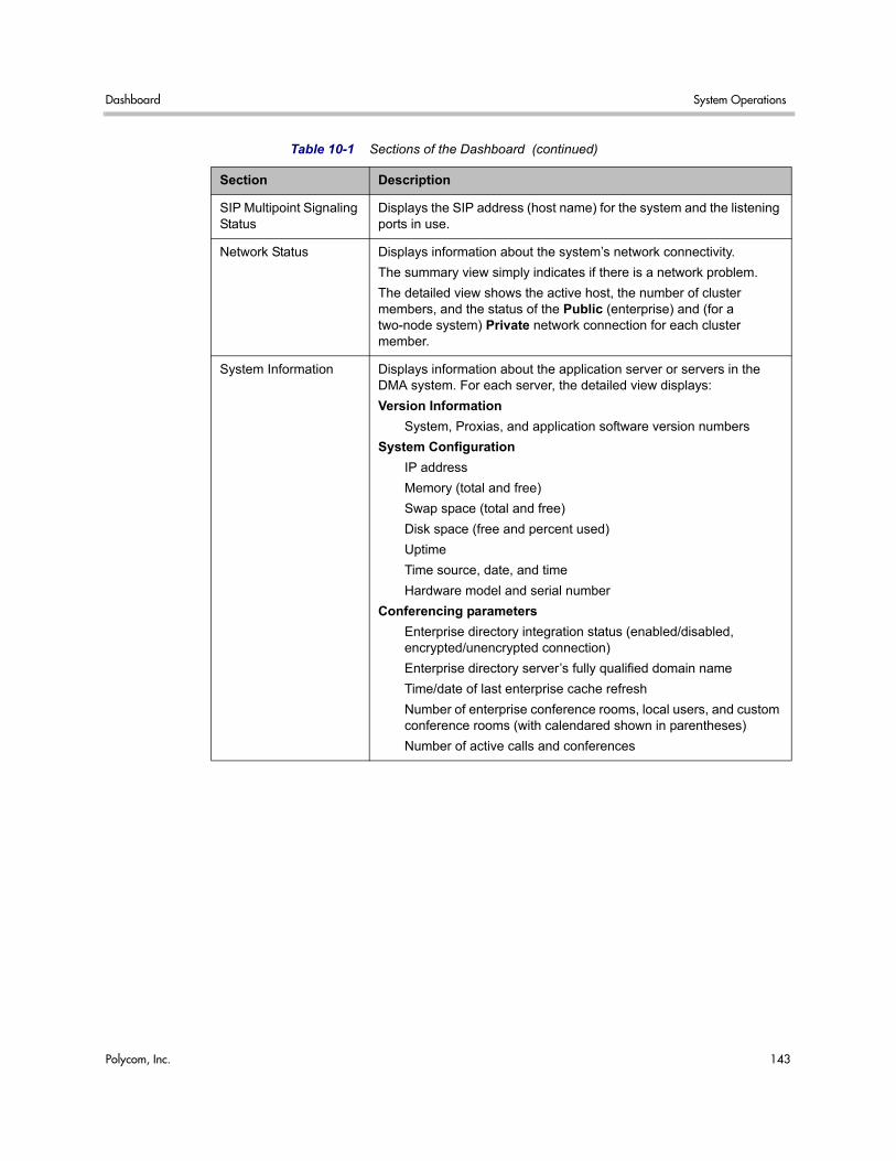
Dashboard System Operations
Polycom, Inc. 143
SIP Multipoint Signaling Status
Displays the SIP address (host name) for the system and the listening ports in use.
Network Status Displays information about the system’s network connectivity.
The summary view simply indicates if there is a network problem.
The detailed view shows the active host, the number of cluster members, and the status of the Public (enterprise) and (for a two-node system) Private network connection for each cluster member.
System Information Displays information about the application server or servers in the DMA system. For each server, the detailed view displays:
Version Information
System, Proxias, and application software version numbers
System Configuration
IP address
Memory (total and free)
Swap space (total and free)
Disk space (free and percent used)
Uptime
Time source, date, and time
Hardware model and serial number
Conferencing parameters
Enterprise directory integration status (enabled/disabled, encrypted/unencrypted connection)
Enterprise directory server’s fully qualified domain name
Time/date of last enterprise cache refresh
Number of enterprise conference rooms, local users, and custom conference rooms (with calendared shown in parentheses)
Number of active calls and conferences
Table 10-1 Sections of the Dashboard (continued)
Section Description
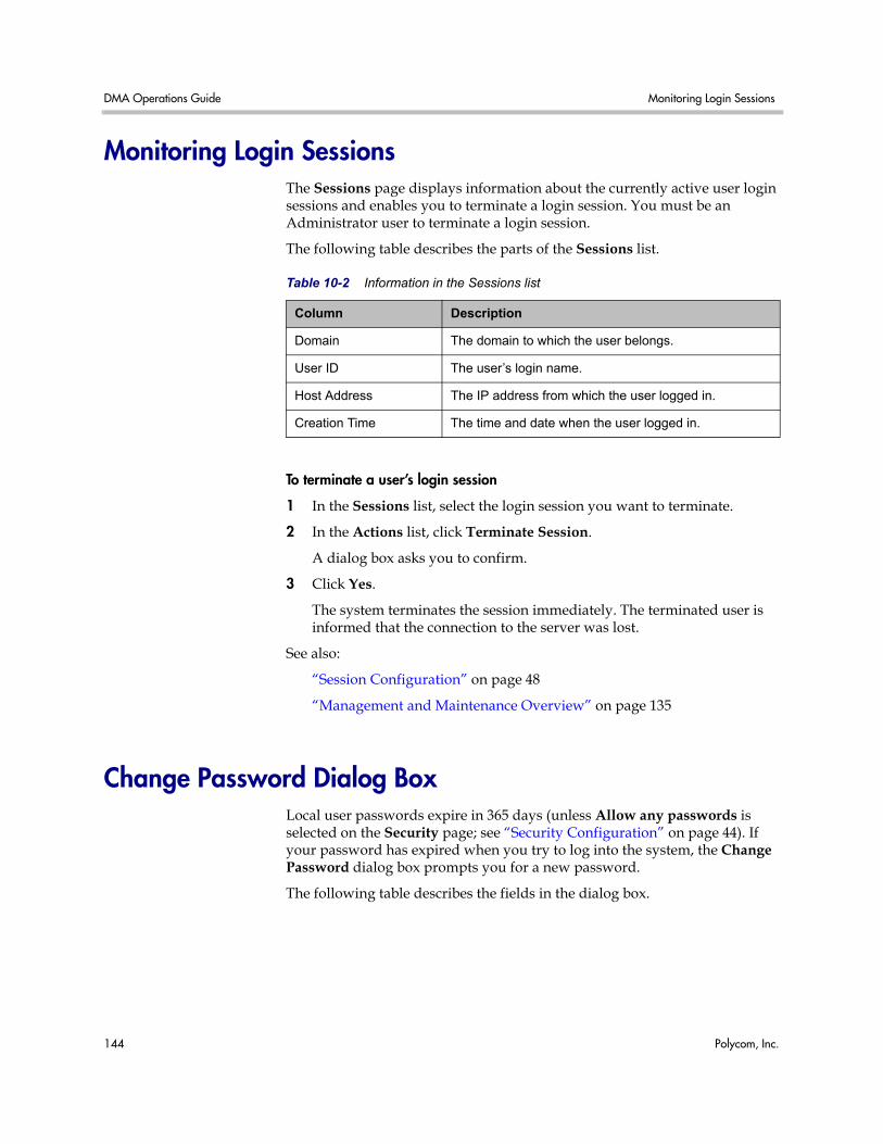
DMA Operations Guide Monitoring Login Sessions
144 Polycom, Inc.
Monitoring Login Sessions The Sessions page displays information about the currently active user login sessions and enables you to terminate a login session. You must be an Administrator user to terminate a login session.
The following table describes the parts of the Sessions list.
To terminate a user’s login session
1 In the Sessions list, select the login session you want to terminate.
2 In the Actions list, click Terminate Session.
A dialog box asks you to confirm.
3 Click Yes.
The system terminates the session immediately. The terminated user is informed that the connection to the server was lost.
See also:
“Session Configuration” on page 48
“Management and Maintenance Overview” on page 135
Change Password Dialog Box Local user passwords expire in 365 days (unless Allow any passwords is selected on the Security page; see “Security Configuration” on page 44). If your password has expired when you try to log into the system, the Change Password dialog box prompts you for a new password.
The following table describes the fields in the dialog box.
Table 10-2 Information in the Sessions list
Column Description
Domain The domain to which the user belongs.
User ID The user’s login name.
Host Address The IP address from which the user logged in.
Creation Time The time and date when the user logged in.
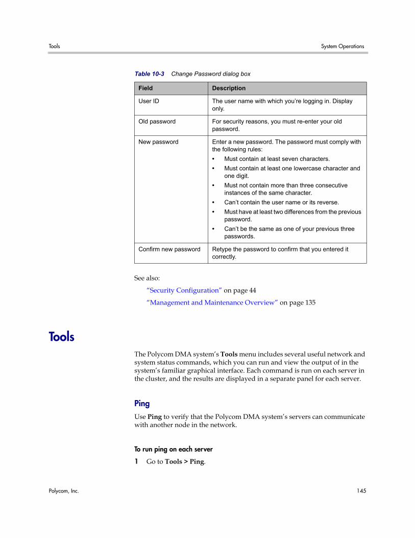
Tools System Operations
Polycom, Inc. 145
See also:
“Security Configuration” on page 44
“Management and Maintenance Overview” on page 135
Tools The Polycom DMA system’s Tools menu includes several useful network and system status commands, which you can run and view the output of in the system’s familiar graphical interface. Each command is run on each server in the cluster, and the results are displayed in a separate panel for each server.
Ping Use Ping to verify that the Polycom DMA system’s servers can communicate with another node in the network.
To run ping on each server
1 Go to Tools > Ping.
Table 10-3 Change Password dialog box
Field Description
User ID The user name with which you’re logging in. Display only.
Old password For security reasons, you must re-enter your old password.
New password Enter a new password. The password must comply with the following rules:
• Must contain at least seven characters.
• Must contain at least one lowercase character and one digit.
• Must not contain more than three consecutive instances of the same character.
• Can’t contain the user name or its reverse.
• Must have at least two differences from the previous password.
• Can’t be the same as one of your previous three passwords.
Confirm new password Retype the password to confirm that you entered it correctly.
DMA Operations Guide Tools
146 Polycom, Inc.
2 Enter an IP address or host name and click Ping.
The system displays results of the command for each server.
Traceroute Use Traceroute to see the route that the servers use to reach the address you specify and the latency (round trip) for each hop.
To run traceroute on each server
1 Go to Tools > Traceroute.
2 Enter an IP address or host name and click Trace.
The system displays results of the command for each server.
Top Use Top to see an overview of each server’s current status, including CPU and memory usage, number of tasks, and list of running processes. The displays update every few seconds.
To run top on each server
>> Go to Tools > Top.
The system displays results of the command for each server.
I/O Stats Use I/O Stats to see CPU resource allocation and read/write statistics for each server.
To run iostat on each server
>> Go to Tools > I/O Stats.
The system displays results of the command for each server.
SAR Use SAR to see a system activity report for each server.
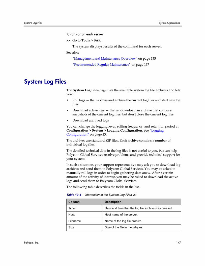
System Log Files System Operations
Polycom, Inc. 147
To run sar on each server
>> Go to Tools > SAR.
The system displays results of the command for each server.
See also:
“Management and Maintenance Overview” on page 135
“Recommended Regular Maintenance” on page 137
System Log Files The System Log Files page lists the available system log file archives and lets you:
• Roll logs — that is, close and archive the current log files and start new log files
• Download active logs — that is, download an archive that contains snapshots of the current log files, but don’t close the current log files
• Download archived logs
You can change the logging level, rolling frequency, and retention period at Configuration > System > Logging Configuration. See “Logging Configuration” on page 23.
The archives are standard ZIP files. Each archive contains a number of individual log files.
The detailed technical data in the log files is not useful to you, but can help Polycom Global Services resolve problems and provide technical support for your system.
In such a situation, your support representative may ask you to download log archives and send them to Polycom Global Services. You may be asked to manually roll logs in order to begin gathering data anew. After a certain amount of the activity of interest, you may be asked to download the active logs and send them to Polycom Global Services.
The following table describes the fields in the list.
Table 10-4 Information in the System Log Files list
Column Description
Time Date and time that the log file archive was created.
Host Host name of the server.
Filename Name of the log file archive.
Size Size of the file in megabytes.
DMA Operations Guide System Log Files
148 Polycom, Inc.
System Logs Procedures
To download logs to your PC or workstation
1 Go to Tools > System Log Files.
The System Log Files page appears.
2 To download a listed log archive:
a Select the file you want.
b In the Actions list, click Download Archived Logs.
c In the dialog box, select a location and click Save.
3 To download an archive of the currently open log files (but not close them):
a In the Actions list, click Download Active Logs.
b In the dialog box, specify a location and file name, and click Save.
To manually roll the system logs
1 Go to Tools > System Log Files.
The System Log Files page appears.
2 In the Actions list, click Roll Logs. Wait a few seconds.
The system closes and archives the current log files and starts writing new ones. A dialog box informs you that logs have been rolled, and the new log archive appears in the System Log Files list.
3 Click OK.
See also:
“Management and Maintenance Overview” on page 135
“Recommended Regular Maintenance” on page 137
“Call History Report” on page 163
“Conference History Report” on page 165
“Export CDR Data” on page 167
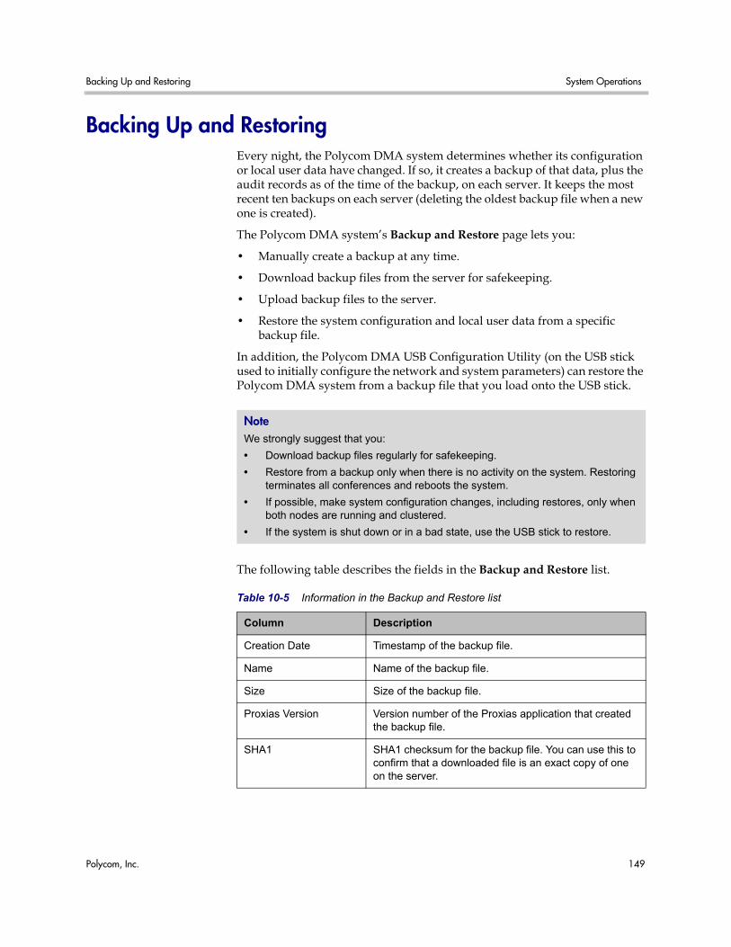
Backing Up and Restoring System Operations
Polycom, Inc. 149
Backing Up and Restoring Every night, the Polycom DMA system determines whether its configuration or local user data have changed. If so, it creates a backup of that data, plus the audit records as of the time of the backup, on each server. It keeps the most recent ten backups on each server (deleting the oldest backup file when a new one is created).
The Polycom DMA system’s Backup and Restore page lets you:
• Manually create a backup at any time.
• Download backup files from the server for safekeeping.
• Upload backup files to the server.
• Restore the system configuration and local user data from a specific backup file.
In addition, the Polycom DMA USB Configuration Utility (on the USB stick used to initially configure the network and system parameters) can restore the Polycom DMA system from a backup file that you load onto the USB stick.
The following table describes the fields in the Backup and Restore list.
Note We strongly suggest that you:
• Download backup files regularly for safekeeping.
• Restore from a backup only when there is no activity on the system. Restoring terminates all conferences and reboots the system.
• If possible, make system configuration changes, including restores, only when both nodes are running and clustered.
• If the system is shut down or in a bad state, use the USB stick to restore.
Table 10-5 Information in the Backup and Restore list
Column Description
Creation Date Timestamp of the backup file.
Name Name of the backup file.
Size Size of the backup file.
Proxias Version Version number of the Proxias application that created the backup file.
SHA1 SHA1 checksum for the backup file. You can use this to confirm that a downloaded file is an exact copy of one on the server.
DMA Operations Guide Backing Up and Restoring
150 Polycom, Inc.
Backup and Restore Procedures
To download a backup file
1 Go to Operations > Backup and Restore.
The list contains the last ten backup files.
2 Select the backup file you want to download.
3 In the Actions list, click Download Selected.
4 Choose a path and filename for the backup file and click Save.
The File Download dialog box indicates when the download is complete.
5 Click Close.
To create a new backup file
1 Go to Operations > Backup and Restore.
2 Verify that the oldest backup file listed is one you don’t want to keep or have already downloaded.
Only ten files are saved. Creating a new backup will delete the oldest file (unless there are fewer than ten).
3 In the Actions list, click Create New.
A confirmation dialog tells you the backup archive was created.
Caution Restoring from a backup requires a system restart and terminates all active conferences.
Note You can’t restore the system while it’s integrated with a Polycom CMA system. The integration must first be terminated. If you try to restore while integrated with a Polycom CMA system, the system asks if you want to terminate the integration. If you agree to do so, the system logs you out, terminates the integration, and restarts. Then you can log back in and run the restore procedure.
Alternatively, you can terminate the integration manually before beginning the restore procedure. See “CMA Integration” on page 24.
Backup files contain site topology data if it was present. When you restore from a backup made while integrated with a Polycom CMA system, the site topology information is restored. But, because the integration with the Polycom CMA system no longer exists, the site topology pages are editable, not read-only.
When you re-integrate with the Polycom CMA system, the saved site topology information is replaced with the current version from the Polycom CMA system, and the pages once again become read-only.
Backing Up and Restoring System Operations
Polycom, Inc. 151
4 Click OK.
To upload a backup file
1 Go to Operations > Backup and Restore.
2 Verify that the oldest backup file listed is one you don’t want to keep or have already downloaded.
Only ten files are saved. Uploading a backup will delete the oldest file (unless there are fewer than ten).
3 In the Actions list, click Upload.
4 Choose a backup file to upload and click Open.
The File Upload dialog box indicates when the upload is complete.
5 Click Close.
The system asks if you want to restore now from the backup file you just uploaded.
6 If you don’t want to restore (and restart the system) now, click Manually Later. When you’re ready to restore, use the procedure that follows this one.
7 To restore now, make sure you meet the criteria in the first step of the following procedure, and click Now. When asked to confirm, click Yes.
A dialog box informs you when all files have been restored.
8 Click OK.
The system logs you out and the server reboots (typically, this takes about five minutes). After it comes back up, in a two-node system, the second node syncs to it, thus being restored to the same state.
To restore from a backup file on the server
1 If this is a two-node system, make sure that both nodes are running and clustered. Make sure that there are no calls on the system, and that all MCUs are out of service. See “MCU Procedures” on page 55.
2 Go to Operations > Backup and Restore.
3 Select the backup file from which you want to restore.
4 In the Actions list, click Restore Selected.
5 When asked to confirm that you want to restore, click Yes.
A dialog box informs you when all files have been restored.
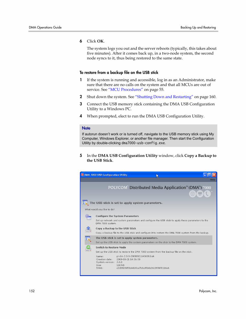
DMA Operations Guide Backing Up and Restoring
152 Polycom, Inc.
6 Click OK.
The system logs you out and the server reboots (typically, this takes about five minutes). After it comes back up, in a two-node system, the second node syncs to it, thus being restored to the same state.
To restore from a backup file on the USB stick
1 If the system is running and accessible, log in as an Administrator, make sure that there are no calls on the system and that all MCUs are out of service. See “MCU Procedures” on page 55.
2 Shut down the system. See “Shutting Down and Restarting” on page 160.
3 Connect the USB memory stick containing the DMA USB Configuration Utility to a Windows PC.
4 When prompted, elect to run the DMA USB Configuration Utility.
5 In the DMA USB Configuration Utility window, click Copy a Backup to the USB Stick.
NoteIf autorun doesn’t work or is turned off, navigate to the USB memory stick using My Computer, Windows Explorer, or another file manager. Then start the Configuration Utility by double-clicking dma7000-usb-config.exe.
Upgrading the Software System Operations
Polycom, Inc. 153
6 Select the backup file from which you want to restore the system and click Open.
The utility displays an error message if the file isn’t a valid Polycom DMA system backup. Otherwise, it confirms that the backup file is in place.
The utility’s main window states that The USB stick is ready to restore the system from a backup file. At the bottom of the window, it displays information about the selected backup file.
7 Close the utility.
8 In your system tray, click Safely Remove Hardware and select Safely Remove USB Mass Storage Device. When a message tells you it’s safe to do so, disconnect the USB memory stick from the PC and take it to the data center housing the Polycom DMA system server(s).
9 Make sure that the node or nodes are turned off. Then insert the USB stick into a USB port on one of the servers and turn that node (but not the other, if there are two) on.
The server boots and the data in the backup file is applied. Typically, this takes about five minutes. Depending on the configuration changes being applied, the server may reboot so the changes can take effect.
10 If this is a two-node system, after the first node has rebooted (if necessary) and its front-panel LCD displays DMA Ready, turn on the second node.
The second node boots, finds the first node, and syncs to it, thus being restored to the same state. Depending on the configuration changes being applied, it may reboot so the changes can take effect.
When done, both servers’ LCDs display DMA Clustered.
See also:
“Management and Maintenance Overview” on page 135
“Recommended Regular Maintenance” on page 137
Upgrading the Software The Polycom DMA system’s Upgrade Management page lets you upload a software upgrade package and install the upgrade on your system (both nodes, if present). It also lets you roll back to the previous version, if necessary.
This process can be used for patches, minor upgrades, and major upgrades. In all three cases, the current system configuration (users, MCUs, conference settings, server settings, and security settings) are preserved.
Patches don’t require new license keys, but major and minor version upgrades do. Any of the three may require a system restart. If so, that information is displayed on the page after you upload the upgrade package.
DMA Operations Guide Upgrading the Software
154 Polycom, Inc.
The following table describes the parts of the Upgrade Management page.
Upgrade Procedures
To install an upgrade
1 Put the upgrade package file somewhere on or accessible from your PC.
2 Go to Operations > Upgrade Management.
3 In the Actions list, click Upload.
Table 10-6 Parts of the Upgrade Management page
Field Description
Version Information Shows the current system version and the rollback version (if any), which is the previous system version.
Upgrade Package Details
Shows the version, SHA1 checksum, and activation key of the upgrade package that’s been uploaded (if any). Also indicates whether the system must be restarted after upgrading and displays a brief description, which includes an estimated install time.
Operation History of Node 1
Lists each upgrade management operation (upgrade or downgrade) performed on node 1, showing the package version, date of the operation, and which user performed it.
Operation History of Node 2
Lists each upgrade management operation (upgrade or downgrade) performed on node 2, showing the package version, date of the operation, and which user performed it.
Note • The upgrade installation process automatically creates a backup, which enables
you to roll back an upgrade (restore the previous version) if necessary. As a precaution, however, we recommend that you download a recent backup file before you begin to install an upgrade. See “Backing Up and Restoring” on page 149.
• You can roll back only the last applied upgrade. Rolling back an upgrade restores the database to its state prior to the upgrade, so data may be lost.
• You can’t upgrade or roll back the system while it’s integrated with a Polycom CMA system. The integration must first be terminated. If you try to upgrade or roll back while integrated with a Polycom CMA system, the system asks if you want to terminate the integration. If you agree to do so, the system logs you out, terminates the integration, and restarts. Then you can log back in and run the upgrade or roll-back procedure.
Alternatively, you can terminate the integration manually before beginning the upgrade or roll-back procedure. See “CMA Integration” on page 24.
Upgrading the Software System Operations
Polycom, Inc. 155
4 Select the upgrade package file and click Open.
The File Upload dialog box indicates when the upload is complete.
5 Click Close.
The Upgrade Package Details section displays information about the file you uploaded. The description includes an estimated install time.
6 Verify that the upgrade package is correct. If a system restart is required, make sure that there are no calls on the system and that all MCUs are out of service. See “MCU Procedures” on page 55.
Most upgrades will require a restart.
7 In the Actions list, click Upgrade.
A confirmation dialog box appears.
8 Click Yes.
If a restart is required, a dialog box informs you that the upgrade is starting. Shortly after that, the system logs you out and restarts.
9 Click OK to log out immediately, or simply wait.
When the upgrade process is finished, in a two-server system, both servers’ LCDs display DMA Clustered (in a single-server system, the LCD displays DMA Ready), and you’re able to log back in.
10 Log back in and:
a In a two-server system, verify on the Dashboard that both servers are up and the private network connection is operating properly.
b Go to Operations> Upgrade Management and check the Operation History tables.
c Go to Device > MCUs and put the MCUs back into service. See “MCU Procedures” on page 55.
11 Call Polycom Global Services if:
— After waiting significantly longer than the estimated install time, you’re still unable to log back in.
— You can log in, but the Dashboard shows only one node for a two-node system.
— The package version numbers on the two nodes are not the same.
Note You may need to restart your browser or flush your browser cache in order to log back into the system.
DMA Operations Guide Upgrading the Software
156 Polycom, Inc.
To roll back an upgrade, restoring the previous version
1 Go to Operations > Upgrade Management.
2 Verify that you want to downgrade the system to the rollback version shown and that you’re prepared for a system restart, if required.
Most rollbacks will require a restart.
3 In the Actions list, click Roll Back.
A confirmation dialog box appears.
4 Click Yes.
If a restart is required, a dialog box informs you that the downgrade is starting. Shortly after that, the system logs you out and restarts.
5 Click OK to log out immediately, or simply wait.
When the downgrade process is finished, in a two-server system, both servers’ LCDs display DMA Clustered (in a single-server system, the LCD displays DMA Ready), and you’re able to log back in.
6 Log back in and:
a In a two-server system, verify on the Dashboard that both servers are up and the private network connection is operating properly.
b Go to Operations > Upgrade Management and check the Operation History tables.
c Go to Device > MCUs and put the MCUs back into service. See “MCU Procedures” on page 55.
7 Call Polycom Global Services if:
— After waiting significantly longer than the estimated install time, you’re still unable to log back in.
— You can log in, but the Dashboard shows only one node for a two-node system.
— The package version numbers on the two nodes are not the same.
See also:
“Management and Maintenance Overview” on page 135
“Recommended Regular Maintenance” on page 137
Note You may need to restart your browser or flush your browser cache in order to log back into the system.
Adding a Second Server System Operations
Polycom, Inc. 157
Adding a Second Server A single-server Polycom DMA system can be upgraded to a fault-tolerant two-node cluster at any time. For an overview of how a two-node cluster works and its advantages, see “Two-node Cluster Configuration” on page 2.
To form a two-node cluster, both servers must be running the same version of the Polycom DMA system software. Depending on the software level of your existing server, you can accomplish this in one of two ways:
• If your existing server is running an unpatched release version of the system software for which you have the installation DVD, follow the first procedure below.
• If your existing server is running a patched version of the system software different from that on the installation DVD, follow the second procedure.
Both procedures assume that you’ve ordered and received the server expansion package, which includes the second server, its accessories, and a new license activation key.
Expanding an Unpatched System
To expand an unpatched single-server system into a two-node cluster
1 Unpack, inspect, and physically install the second server as described in its Getting Started Guide. Mount it in the rack adjacent to the first Polycom DMA system server (or close enough to connect them with one of the provided crossover Ethernet cables).
2 Log into your Polycom DMA system, go to Configuration > System > Network, and add the Node 2 host name and IP address for the second server. See “Network” on page 17.
The first server (Node 1) reboots.
3 Connect the second server to the network:
a Connect the GB 1 Ethernet port of the new server to the enterprise network.
Note You can’t add a server to the system while it’s integrated with a Polycom CMA system. The integration must first be terminated. If you try to add a server while integrated with a Polycom CMA system, the system asks if you want to terminate the integration. If you agree to do so, the system logs you out, terminates the integration, and restarts. Then you can log back in and run the appropriate server expansion procedure.
Alternatively, you can terminate the integration manually before beginning the server expansion procedure. See “CMA Integration” on page 24.
DMA Operations Guide Adding a Second Server
158 Polycom, Inc.
b Use one of the provided crossover cables to connect the GB 2 ports of the two servers.
4 Confirm that the first server is running and displays DMA Ready. Then turn on the second server, insert the installation DVD, and reboot it.
The server boots from the DVD, and the installation commences. About 15-20 minutes later, the DVD ejects and the server reboots. It detects the presence of Node 1, gets its configuration settings from it, and joins the cluster. When done, both servers’ LCDs display DMA Clustered.
5 Log into the system, go to Configuration > System > License and Capabilities, and enter the new activation key for the second server. See “License and Capabilities” on page 20.
6 On the Dashboard, check the License Status, Network Status, and System Information sections to verify that you now have a properly configured two-node cluster.
Expanding a Patched System
To expand a patched single-server system into a two-node cluster
1 Unpack, inspect, and physically install the second server as described in its Getting Started Guide. Mount it in the rack adjacent to the first Polycom DMA system server (or close enough to connect them with one of the provided crossover Ethernet cables).
2 Connect the GB 1 Ethernet port of the new server to the enterprise network. Don’t connect the crossover cable between the two servers at this time.
3 Log into your existing Polycom DMA system and determine the software version (including patch level) installed on the first (existing) server. Write it down for later reference.
4 Go to Configuration > System > Network, and add the Node 2 host name and IP address for the second server. See “Network” on page 17.
The first server (Node 1) reboots.
5 Shut down the first server (Node 1).
6 Using the USB Configuration Utility and the procedure in the Getting Started Guide, complete the installation and initial configuration of the new server as a stand-alone single-node system. If necessary, use your installation DVD to install the same release version of the software that’s on your first server.
Caution The first server must be running properly before you turn on the second server.
Adding a Second Server System Operations
Polycom, Inc. 159
7 Log into the new server, go to Operations > Upgrade Management, and install the patch(es) needed to make it match the software version on the first server. See “Upgrading the Software” on page 153.
8 Shut down the new server. See “Shutting Down and Restarting” on page 160.
9 Use one of the provided crossover cables to connect the GB 2 ports of the two servers.
10 Turn on the first server (Node 1).
11 When the first server displays DMA Ready, turn on the second server.
The second server boots, detects the presence of Node 1, gets its configuration settings from it, and joins the cluster. When done, both servers’ LCDs display DMA Clustered.
12 Log into the system, go to Configuration > System > License and Capabilities, and enter the new activation key for the second server. See “License and Capabilities” on page 20.
13 On the Dashboard, check the License Status, Network Status, and System Information sections to verify that you now have a properly configured two-node cluster.
See also:
“Management and Maintenance Overview” on page 135
“Recommended Regular Maintenance” on page 137
Caution Assign the new server its own real and virtual IP addresses. Don’t assign it the virtual IP address of the existing system.
Caution The first server must be running properly before you turn on the second server.
DMA Operations Guide Replacing a Failed Server
160 Polycom, Inc.
Replacing a Failed Server Replacing a server is essentially the same process as adding a second server to a single-server system. As in that situation, you must make sure that both servers are running the same version of the Polycom DMA system software.
The procedure assumes that you’ve gone through the RMA process and received the replacement server package, which includes the server, its accessories, and a new license activation key.
To replace a failed server in a two-node cluster
1 If you haven’t already done so, power down, uncable, and remove the failed server.
2 Log into your Polycom DMA system and determine the software version (including patch level) installed on the remaining server. Write it down for later reference.
3 Do one of the following:
— If your system is running an unpatched release version of the system software for which you have the installation DVD, follow the procedure in “Expanding an Unpatched System” on page 157, skipping step 2.
— If your system is running a patched version of the system software different from that on the installation DVD, follow the procedure in “Expanding a Patched System” on page 158, skipping steps 3 and 4.
See also:
“Management and Maintenance Overview” on page 135
“Recommended Regular Maintenance” on page 137
Shutting Down and Restarting The Polycom DMA system’s Power Management page lets you restart the system or turn it off completely. These commands affect both servers in a two-node cluster.
Both shutting down and restarting will terminate all existing calls and log out all current users.
To restart or shut down both servers
1 Go to Operations > Power Management.
2 Do one of the following:
— To restart the system, click Restart.
Shutting Down and Restarting System Operations
Polycom, Inc. 161
— To shut down the system (turn off both servers), click Shut Down.
3 When asked to confirm that you want to restart or shut down, click Yes.
The system logs you out and each server shuts down. If you chose Restart, the server(s) reboot, and conference service becomes available again when the restart is complete (typically, this takes about five minutes).
If you chose Shut Down, the server(s) remain powered off until you manually turn them back on.
See also:
“Management and Maintenance Overview” on page 135
“Recommended Regular Maintenance” on page 137

DMA Operations Guide Shutting Down and Restarting
162 Polycom, Inc.
Polycom, Inc. 163
11System Reports
This chapter describes the following Polycom® Distributed Media Application™ (DMA™) 7000 system reports topics:
• Call History Report
• Conference History Report
• Export CDR Data
• Enterprise Directory Integration Report
• Orphaned Groups and Users Report
• Conference Room Errors Report
• Export Conference Room Errors Data
• Enterprise Password Errors Report
• Export Enterprise Password Errors Data
Call History Report The Call History page lets you view detailed records of calls and download CDRs (call detail records).
The fields at the top of the page let you select the starting and ending date and time for which you want to view call records.
When setting the date/time range for your search, keep in mind that retrieving a large number of records can take some time.
After you search for calls, the Call History page lists the calls in the time range you specified. If there are more than 500, the first page lists the first 500, and the arrow buttons below the list let you view other pages.
When you select a call associated with a conference, the Display Conference command (in the Actions list) switches from the Call History page to the Conference History page, displaying the associated conference.
The following table describes the fields in the list.
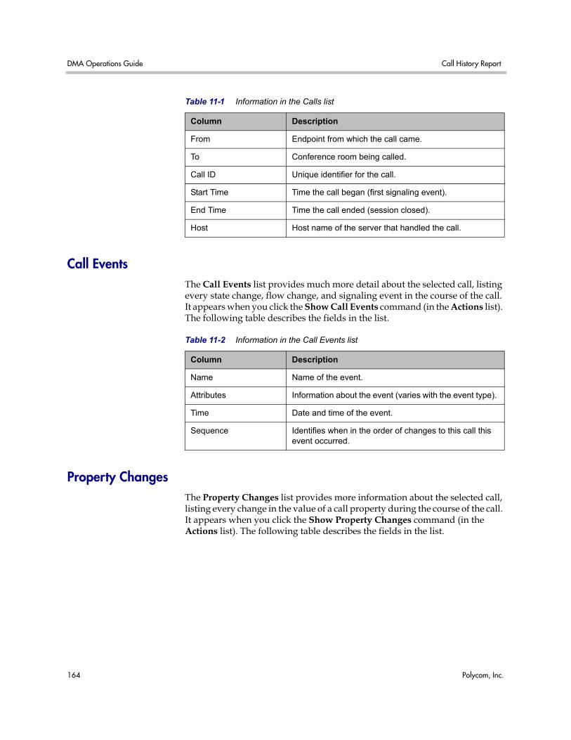
DMA Operations Guide Call History Report
164 Polycom, Inc.
Call Events The Call Events list provides much more detail about the selected call, listing every state change, flow change, and signaling event in the course of the call. It appears when you click the Show Call Events command (in the Actions list). The following table describes the fields in the list.
Property Changes The Property Changes list provides more information about the selected call, listing every change in the value of a call property during the course of the call. It appears when you click the Show Property Changes command (in the Actions list). The following table describes the fields in the list.
Table 11-1 Information in the Calls list
Column Description
From Endpoint from which the call came.
To Conference room being called.
Call ID Unique identifier for the call.
Start Time Time the call began (first signaling event).
End Time Time the call ended (session closed).
Host Host name of the server that handled the call.
Table 11-2 Information in the Call Events list
Column Description
Name Name of the event.
Attributes Information about the event (varies with the event type).
Time Date and time of the event.
Sequence Identifies when in the order of changes to this call this event occurred.
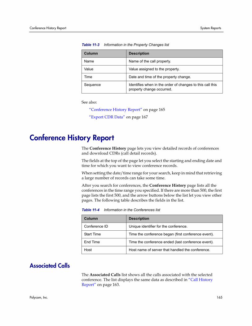
Conference History Report System Reports
Polycom, Inc. 165
See also:
“Conference History Report” on page 165
“Export CDR Data” on page 167
Conference History Report The Conference History page lets you view detailed records of conferences and download CDRs (call detail records).
The fields at the top of the page let you select the starting and ending date and time for which you want to view conference records.
When setting the date/time range for your search, keep in mind that retrieving a large number of records can take some time.
After you search for conferences, the Conference History page lists all the conferences in the time range you specified. If there are more than 500, the first page lists the first 500, and the arrow buttons below the list let you view other pages. The following table describes the fields in the list.
Associated Calls The Associated Calls list shows all the calls associated with the selected conference. The list displays the same data as described in “Call History Report” on page 163.
Table 11-3 Information in the Property Changes list
Column Description
Name Name of the call property.
Value Value assigned to the property.
Time Date and time of the property change.
Sequence Identifies when in the order of changes to this call this property change occurred.
Table 11-4 Information in the Conferences list
Column Description
Conference ID Unique identifier for the conference.
Start Time Time the conference began (first conference event).
End Time Time the conference ended (last conference event).
Host Host name of server that handled the conference.
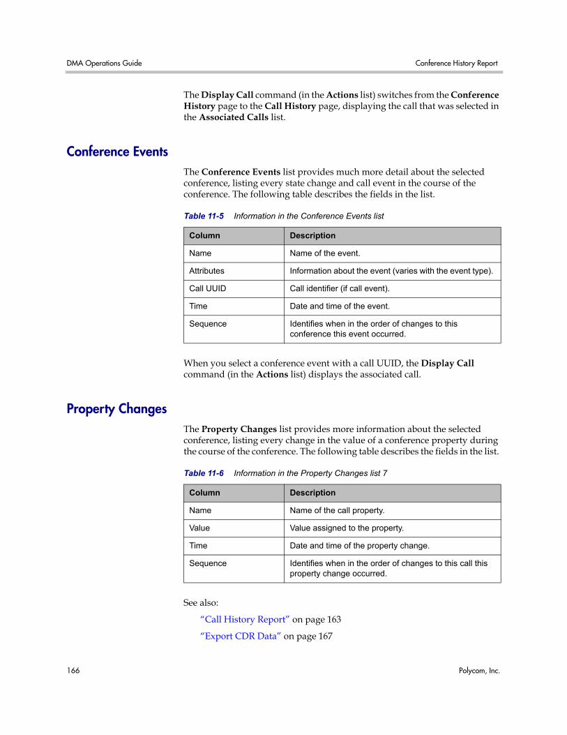
DMA Operations Guide Conference History Report
166 Polycom, Inc.
The Display Call command (in the Actions list) switches from the Conference History page to the Call History page, displaying the call that was selected in the Associated Calls list.
Conference Events The Conference Events list provides much more detail about the selected conference, listing every state change and call event in the course of the conference. The following table describes the fields in the list.
When you select a conference event with a call UUID, the Display Call command (in the Actions list) displays the associated call.
Property Changes The Property Changes list provides more information about the selected conference, listing every change in the value of a conference property during the course of the conference. The following table describes the fields in the list.
See also:
“Call History Report” on page 163
“Export CDR Data” on page 167
Table 11-5 Information in the Conference Events list
Column Description
Name Name of the event.
Attributes Information about the event (varies with the event type).
Call UUID Call identifier (if call event).
Time Date and time of the event.
Sequence Identifies when in the order of changes to this conference this event occurred.
Table 11-6 Information in the Property Changes list 7
Column Description
Name Name of the call property.
Value Value assigned to the property.
Time Date and time of the property change.
Sequence Identifies when in the order of changes to this call this property change occurred.
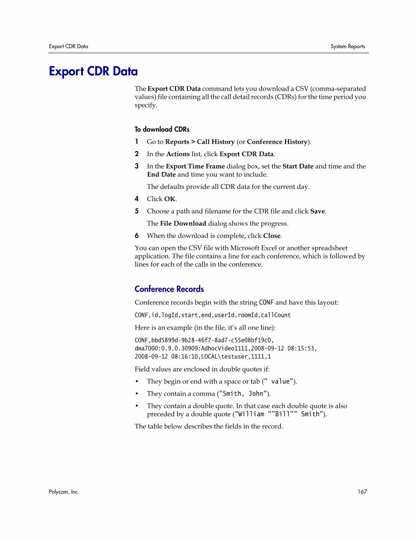
Export CDR Data System Reports
Polycom, Inc. 167
Export CDR Data The Export CDR Data command lets you download a CSV (comma-separated values) file containing all the call detail records (CDRs) for the time period you specify.
To download CDRs
1 Go to Reports > Call History (or Conference History).
2 In the Actions list, click Export CDR Data.
3 In the Export Time Frame dialog box, set the Start Date and time and the End Date and time you want to include.
The defaults provide all CDR data for the current day.
4 Click OK.
5 Choose a path and filename for the CDR file and click Save.
The File Download dialog shows the progress.
6 When the download is complete, click Close.
You can open the CSV file with Microsoft Excel or another spreadsheet application. The file contains a line for each conference, which is followed by lines for each of the calls in the conference.
Conference Records Conference records begin with the string CONF and have this layout:
CONF,id,logId,start,end,userId,roomId,callCount
Here is an example (in the file, it’s all one line):
CONF,bbd5899d-9b28-46f7-8ad7-c55e08bf19c0,dma7000:0.9.0.30909:AdhocVideo1111,2008-09-12 08:15:53,2008-09-12 08:16:10,LOCAL\testuser,1111,1
Field values are enclosed in double quotes if:
• They begin or end with a space or tab (" value").
• They contain a comma ("Smith, John").
• They contain a double quote. In that case each double quote is also preceded by a double quote ("William ""Bill"" Smith").
The table below describes the fields in the record.
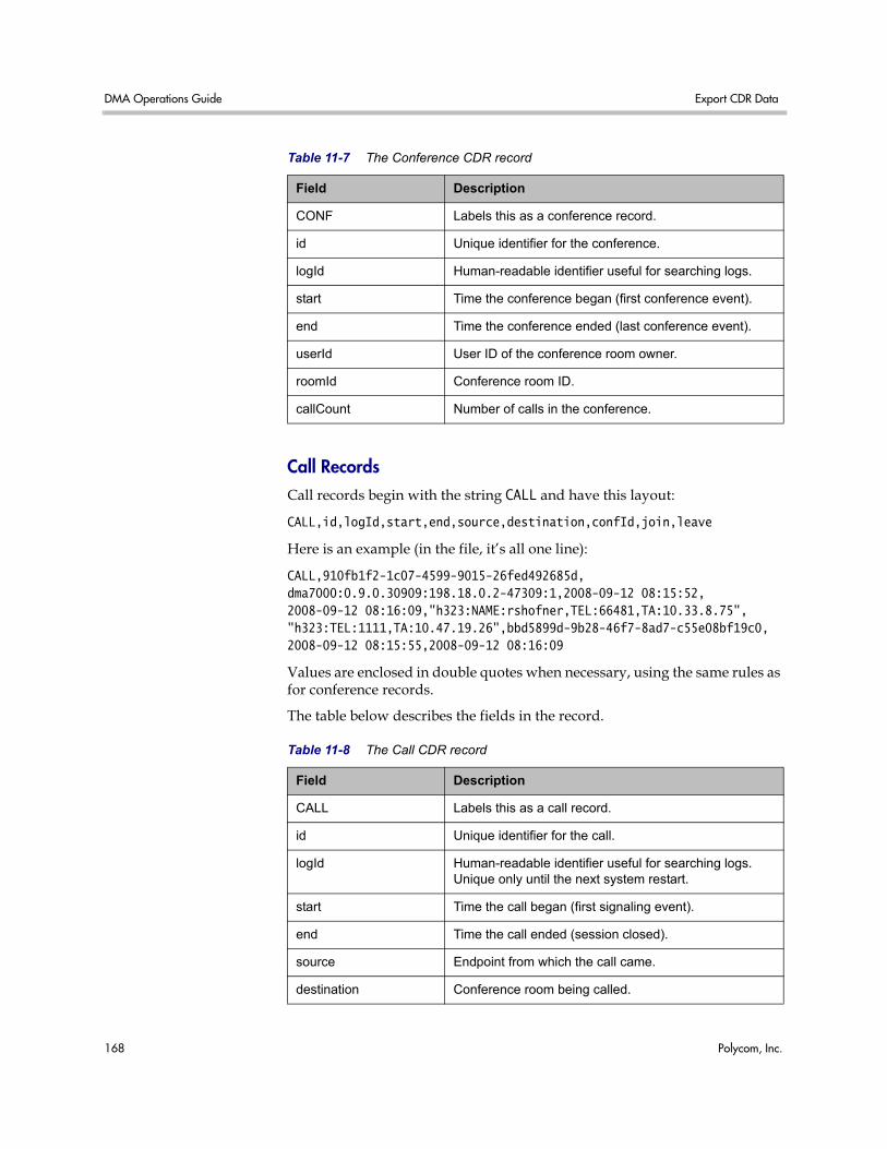
DMA Operations Guide Export CDR Data
168 Polycom, Inc.
Call Records Call records begin with the string CALL and have this layout:
CALL,id,logId,start,end,source,destination,confId,join,leave
Here is an example (in the file, it’s all one line):
CALL,910fb1f2-1c07-4599-9015-26fed492685d,dma7000:0.9.0.30909:198.18.0.2-47309:1,2008-09-12 08:15:52,2008-09-12 08:16:09,"h323:NAME:rshofner,TEL:66481,TA:10.33.8.75","h323:TEL:1111,TA:10.47.19.26",bbd5899d-9b28-46f7-8ad7-c55e08bf19c0,2008-09-12 08:15:55,2008-09-12 08:16:09
Values are enclosed in double quotes when necessary, using the same rules as for conference records.
The table below describes the fields in the record.
Table 11-7 The Conference CDR record
Field Description
CONF Labels this as a conference record.
id Unique identifier for the conference.
logId Human-readable identifier useful for searching logs.
start Time the conference began (first conference event).
end Time the conference ended (last conference event).
userId User ID of the conference room owner.
roomId Conference room ID.
callCount Number of calls in the conference.
Table 11-8 The Call CDR record
Field Description
CALL Labels this as a call record.
id Unique identifier for the call.
logId Human-readable identifier useful for searching logs. Unique only until the next system restart.
start Time the call began (first signaling event).
end Time the call ended (session closed).
source Endpoint from which the call came.
destination Conference room being called.
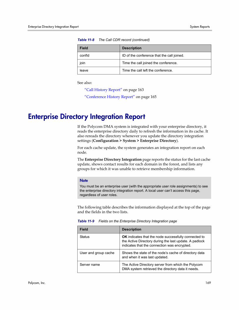
Enterprise Directory Integration Report System Reports
Polycom, Inc. 169
See also:
“Call History Report” on page 163
“Conference History Report” on page 165
Enterprise Directory Integration Report If the Polycom DMA system is integrated with your enterprise directory, it reads the enterprise directory daily to refresh the information in its cache. It also rereads the directory whenever you update the directory integration settings (Configuration > System > Enterprise Directory).
For each cache update, the system generates an integration report on each node.
The Enterprise Directory Integration page reports the status for the last cache update, shows contact results for each domain in the forest, and lists any groups for which it was unable to retrieve membership information.
The following table describes the information displayed at the top of the page and the fields in the two lists.
confId ID of the conference that the call joined.
join Time the call joined the conference.
leave Time the call left the conference.
Table 11-8 The Call CDR record (continued)
Field Description
Note You must be an enterprise user (with the appropriate user role assignments) to see the enterprise directory integration report. A local user can’t access this page, regardless of user roles.
Table 11-9 Fields on the Enterprise Directory Integration page
Field Description
Status OK indicates that the node successfully connected to the Active Directory during the last update. A padlock indicates that the connection was encrypted.
User and group cache Shows the state of the node’s cache of directory data and when it was last updated.
Server name The Active Directory server from which the Polycom DMA system retrieved the directory data it needs.
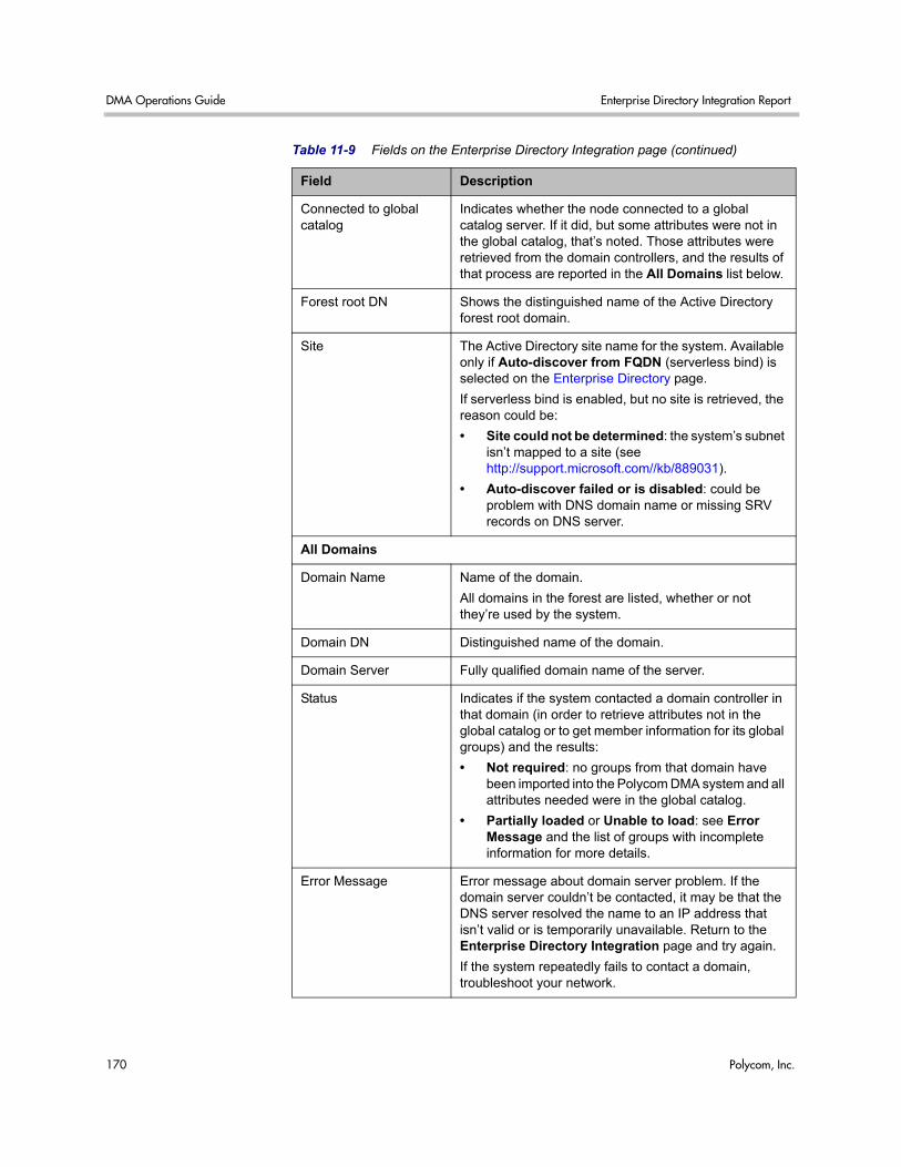
DMA Operations Guide Enterprise Directory Integration Report
170 Polycom, Inc.
Connected to global catalog
Indicates whether the node connected to a global catalog server. If it did, but some attributes were not in the global catalog, that’s noted. Those attributes were retrieved from the domain controllers, and the results of that process are reported in the All Domains list below.
Forest root DN Shows the distinguished name of the Active Directory forest root domain.
Site The Active Directory site name for the system. Available only if Auto-discover from FQDN (serverless bind) is selected on the Enterprise Directory page.
If serverless bind is enabled, but no site is retrieved, the reason could be:
• Site could not be determined: the system’s subnet isn’t mapped to a site (see http://support.microsoft.com//kb/889031).
• Auto-discover failed or is disabled: could be problem with DNS domain name or missing SRV records on DNS server.
All Domains
Domain Name Name of the domain.
All domains in the forest are listed, whether or not they’re used by the system.
Domain DN Distinguished name of the domain.
Domain Server Fully qualified domain name of the server.
Status Indicates if the system contacted a domain controller in that domain (in order to retrieve attributes not in the global catalog or to get member information for its global groups) and the results:
• Not required: no groups from that domain have been imported into the Polycom DMA system and all attributes needed were in the global catalog.
• Partially loaded or Unable to load: see Error Message and the list of groups with incomplete information for more details.
Error Message Error message about domain server problem. If the domain server couldn’t be contacted, it may be that the DNS server resolved the name to an IP address that isn’t valid or is temporarily unavailable. Return to the Enterprise Directory Integration page and try again.
If the system repeatedly fails to contact a domain, troubleshoot your network.
Table 11-9 Fields on the Enterprise Directory Integration page (continued)
Field Description
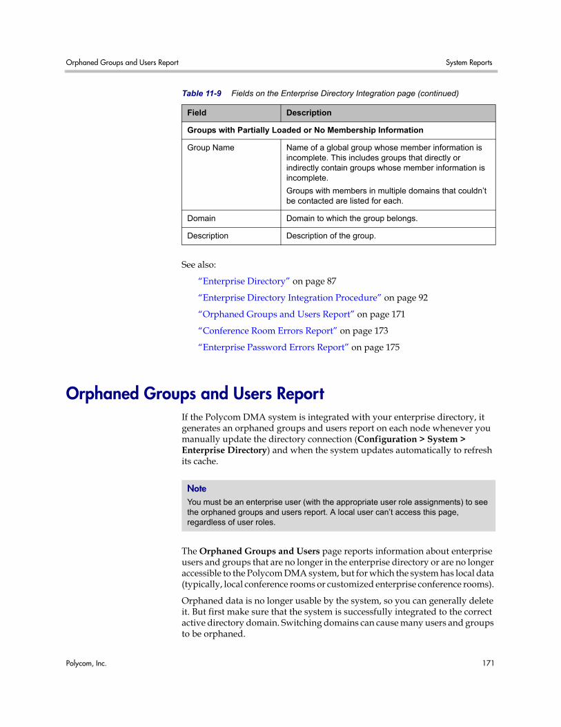
Orphaned Groups and Users Report System Reports
Polycom, Inc. 171
See also:
“Enterprise Directory” on page 87
“Enterprise Directory Integration Procedure” on page 92
“Orphaned Groups and Users Report” on page 171
“Conference Room Errors Report” on page 173
“Enterprise Password Errors Report” on page 175
Orphaned Groups and Users Report If the Polycom DMA system is integrated with your enterprise directory, it generates an orphaned groups and users report on each node whenever you manually update the directory connection (Configuration > System > Enterprise Directory) and when the system updates automatically to refresh its cache.
The Orphaned Groups and Users page reports information about enterprise users and groups that are no longer in the enterprise directory or are no longer accessible to the Polycom DMA system, but for which the system has local data (typically, local conference rooms or customized enterprise conference rooms).
Orphaned data is no longer usable by the system, so you can generally delete it. But first make sure that the system is successfully integrated to the correct active directory domain. Switching domains can cause many users and groups to be orphaned.
Groups with Partially Loaded or No Membership Information
Group Name Name of a global group whose member information is incomplete. This includes groups that directly or indirectly contain groups whose member information is incomplete.
Groups with members in multiple domains that couldn’t be contacted are listed for each.
Domain Domain to which the group belongs.
Description Description of the group.
Table 11-9 Fields on the Enterprise Directory Integration page (continued)
Field Description
Note You must be an enterprise user (with the appropriate user role assignments) to see the orphaned groups and users report. A local user can’t access this page, regardless of user roles.
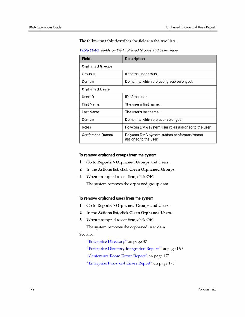
DMA Operations Guide Orphaned Groups and Users Report
172 Polycom, Inc.
The following table describes the fields in the two lists.
To remove orphaned groups from the system
1 Go to Reports > Orphaned Groups and Users.
2 In the Actions list, click Clean Orphaned Groups.
3 When prompted to confirm, click OK.
The system removes the orphaned group data.
To remove orphaned users from the system
1 Go to Reports > Orphaned Groups and Users.
2 In the Actions list, click Clean Orphaned Users.
3 When prompted to confirm, click OK.
The system removes the orphaned user data.
See also:
“Enterprise Directory” on page 87
“Enterprise Directory Integration Report” on page 169
“Conference Room Errors Report” on page 173
“Enterprise Password Errors Report” on page 175
Table 11-10 Fields on the Orphaned Groups and Users page
Field Description
Orphaned Groups
Group ID ID of the user group.
Domain Domain to which the user group belonged.
Orphaned Users
User ID ID of the user.
First Name The user’s first name.
Last Name The user’s last name.
Domain Domain to which the user belonged.
Roles Polycom DMA system user roles assigned to the user.
Conference Rooms Polycom DMA system custom conference rooms assigned to the user.
Conference Room Errors Report System Reports
Polycom, Inc. 173
Conference Room Errors Report If the Polycom DMA system is integrated with your enterprise directory, it can create a conference room (virtual meeting room) for each enterprise user. See “Enterprise Directory” on page 87.
The Polycom DMA system reads the enterprise directory daily to refresh the information in its cache. It also rereads the directory whenever you update the directory integration settings (Configuration > System > Enterprise Directory).
If the directory integration settings are configured to generate conference room IDs for enterprise users, the Polycom DMA system retrieves the values from the designated directory attribute and removes the specified characters from them. If the resulting room ID is longer than the specified maximum, it strips the excess characters from the beginning of the string.
The Conference Room Errors page reports the conference room ID generation status and lists the problem IDs.
The summary at the top of the report shows when it was generated (check this to verify that the report you’re viewing reflects the most recent update of the cache) and the following information:
• Number of users in the directory
• Number of users with valid conference room IDs
If you don’t specify a directory attribute from which to generate conference room IDs, this number is zero and the report contains nothing else of value.
• Number of users for whom the enterprise directory field being used to generate conference room IDs is empty (these are counted, but not listed individually below; find them in the enterprise directory)
• Number of blank conference room IDs (doesn’t include those for whom the enterprise directory field was empty, only those for whom its contents were filtered out)
• Number of invalid conference room IDs
• Number of duplicate conference room IDs
The blank, invalid, and duplicate conference room IDs are listed below.
Note You must be an enterprise user (with the appropriate user role assignments) to see the conference room errors report. A local user can’t access this page, regardless of user roles.
DMA Operations Guide Conference Room Errors Report
174 Polycom, Inc.
The following table describes the fields in the list.
See also:
“Export Conference Room Errors Data” on page 175
“Enterprise Directory” on page 87
“Enterprise Directory Integration Report” on page 169
“Orphaned Groups and Users Report” on page 171
“Enterprise Password Errors Report” on page 175
Note Duplicate conference room IDs are not disabled; they can be used for conferencing. But if both users associated with that conference room ID try to hold a conference at the same time, they end up in the same conference.
Table 11-11 Information in the Conference Room Errors list
Column Description
Problem Description of the issue with this room ID (Blank, Duplicate, or Invalid).
Conference Room ID The conference room ID, typically generated from the enterprise user’s phone number.
<directory attribute> The attribute (field) from the enterprise directory that’s used to generate the room ID (see “Enterprise Directory” on page 87). The column heading is the name of the attribute, such as telephoneNumber.
User ID The login name or ID of the enterprise user with this room ID.
Domain The domain to which the enterprise user belongs.
Last Name The enterprise user’s last name.
First Name The enterprise user’s first name.
Notes For duplicates, identifies the domain and user ID of the user with a duplicate conference room ID.
Export Conference Room Errors Data System Reports
Polycom, Inc. 175
Export Conference Room Errors Data The Export Room Errors Data command lets you download a CSV (comma-separated values) file containing all the data in the conference room errors report.
To download conference room errors data
1 Go to Reports > Conference Room Errors.
2 In the Actions list, click Export Room Errors Data.
3 In the Exporting Conference Room Errors Report dialog box, click Download.
4 Choose a path and filename for the file and click Save.
The File Download dialog shows the progress.
5 When the download is complete, click Close.
You can open the CSV file with Microsoft Excel or another spreadsheet application. The file contains the same data you see displayed on the Conference Room Errors page.
See also:
“Conference Room Errors Report” on page 173
Enterprise Password Errors Report If the Polycom DMA system is integrated with your enterprise directory, conference and chairperson passwords for enterprise users can be maintained in the enterprise directory. See “Adding Passwords for Enterprise Users” on page 97.
The Polycom DMA system reads the enterprise directory daily to refresh the information in its cache. It also rereads the directory whenever you update the directory integration settings (Configuration > System > Enterprise Directory).
If the directory integration settings are configured to generate passwords for enterprise users, the Polycom DMA system retrieves the values from the designated directory attributes and removes any non-numeric characters from them. If the resulting numeric password is longer than the specified maximum for that password type, it strips the excess characters from the beginning of the string.
The Enterprise Password Errors page reports the password generation status and lists the users with password errors.
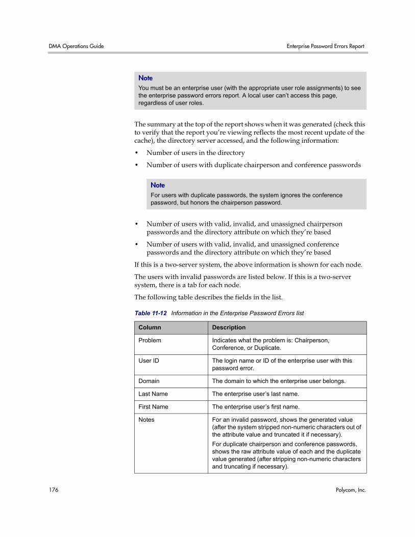
DMA Operations Guide Enterprise Password Errors Report
176 Polycom, Inc.
The summary at the top of the report shows when it was generated (check this to verify that the report you’re viewing reflects the most recent update of the cache), the directory server accessed, and the following information:
• Number of users in the directory
• Number of users with duplicate chairperson and conference passwords
• Number of users with valid, invalid, and unassigned chairperson passwords and the directory attribute on which they’re based
• Number of users with valid, invalid, and unassigned conference passwords and the directory attribute on which they’re based
If this is a two-server system, the above information is shown for each node.
The users with invalid passwords are listed below. If this is a two-server system, there is a tab for each node.
The following table describes the fields in the list.
Note You must be an enterprise user (with the appropriate user role assignments) to see the enterprise password errors report. A local user can’t access this page, regardless of user roles.
Note For users with duplicate passwords, the system ignores the conference password, but honors the chairperson password.
Table 11-12 Information in the Enterprise Password Errors list
Column Description
Problem Indicates what the problem is: Chairperson, Conference, or Duplicate.
User ID The login name or ID of the enterprise user with this password error.
Domain The domain to which the enterprise user belongs.
Last Name The enterprise user’s last name.
First Name The enterprise user’s first name.
Notes For an invalid password, shows the generated value (after the system stripped non-numeric characters out of the attribute value and truncated it if necessary).
For duplicate chairperson and conference passwords, shows the raw attribute value of each and the duplicate value generated (after stripping non-numeric characters and truncating if necessary).
Export Enterprise Password Errors Data System Reports
Polycom, Inc. 177
See also:
“Export Enterprise Password Errors Data” on page 177
“Adding Passwords for Enterprise Users” on page 97
“Enterprise Directory” on page 87
“Enterprise Directory Integration Report” on page 169
“Orphaned Groups and Users Report” on page 171
“Conference Room Errors Report” on page 173
Export Enterprise Password Errors Data The Export Enterprise Password Errors Data command lets you download a CSV (comma-separated values) file containing all the data in the enterprise password errors report.
To download enterprise password errors data
1 Go to Reports > Enterprise Password Errors.
2 In the Actions list, click Export Enterprise Password Errors Data.
3 In the Exporting Enterprise Password Errors Report dialog box, click Download.
4 Choose a path and filename for the file and click Save.
The File Download dialog shows the progress.
5 When the download is complete, click Close.
You can open the CSV file with Microsoft Excel or another spreadsheet application. The file contains the same data you see displayed on the Enterprise Password Errors page.
See also:
“Enterprise Password Errors Report” on page 175

DMA Operations Guide Export Enterprise Password Errors Data
178 Polycom, Inc.
Polycom, Inc. 179
Index
Aaccess, system interface 3activation keys 20Active Directory 13, 87
integration 92integration report 169
add conference templates dialog 69add MCU dialog 54add MCU zone dialog 58, 62adding
DNS record 10enterprise passwords 97MCU 55second server 157users 117
ASCII 5audit data 163, 165
Bbacking up 149best practices 135busy out MCU 55
Ccalendaring 83call history 163cascading 68CDR data, export 167CDRs 163, 165certificate
details dialog 39information dialog 37install CA 40install dialog 38install signed 42management list 36overview 33procedures 39remove 43signing request 41
signing request dialog 38change password dialog 144clustering 1, 2CMA integration 24, 26, 31commands, system monitoring 145conference
cascading 68IVR service 67
conference appointments 83conference history 165conference passwords
enterprise errors report 175enterprise users 97export errors data 177local user 120
conference roomerrors report 173export errors data 175procedures 128
conference settings 82conference setup 65conference templates
add dialog 69assigning to enterprise groups 132edit dialog 74procedures 80screen 65setting up 14video frame layout 79
configurationbackup 149calendar 83logging 23login sessions 48security 44signaling 11, 21single-server 2site topology 105system 17tasks 9two-node cluster 2
DMA Operations Guide
180 Polycom, Inc.
configuration, system 26connect to enterprise directory 13
Ddashboard 140date and time settings 19defaults, conference 82description, system 1details, certificate 39device management 51dial string prefix 21directory, enterprise 13, 87DNS record 10download
CDRs 167enterprise password errors data 177room errors data 175
duration, conference 82
Eedit conference templates dialog 74edit MCU dialog 54edit MCU zone dialog 59, 63email meeting appointments 83enterprise directory 13
integration 87, 92integration report 169settings 87
enterprise groups 130, 132enterprise password
adding 97errors report 175export errors data 177
errorsconference room 173enterprise password 175
Exchange server integration 83expansion, system 157export
CDR data 167enterprise password errors data 177invalid conference rooms data 175
Ffailed server, replacing 160fault tolerance 1, 2field input requirements 5
Ggatekeeper 11, 21groups, enterprise 130, 132groups, orphaned 171
HH.323 prefix 21halting system 160hardware
replacing 160upgrading 157
history retention 24history, call 163history, conference 165
Iinformation, certificate 37initial setup 9
add DNS record 10conference templates 14configure signaling 11enterprise directory 13license the system 10MCUs 12security 11testing 14
input fields 5install certificates dialog 38integration
enterprise directory 87integration report, enterprise directory 169integration, CMA 24, 26, 31integration, enterprise directory 92interface access 3introduction to system 1introductory video 5invalid conference rooms 173invalid enterprise passwords 175iostat command 146IVR service 67
Jjoin CMA 26, 31
Llayout, video frame 79LDAP 13, 87, 92leave CMA 31
Index
Polycom, Inc. 181
license the system 10licenses
open source software 6system 20
logging configuration 23login sessions 144login sessions, settings 48logs, system 147
Mmaintenance
overview 135recommended 137
managementcertificate 36device 51overview 135system 135users and groups 115
MCUadd dialog 54edit dialog 54list 51management 51procedures 55setting up 12
MCU zoneedit dialog 59, 63procedures 59, 63
MCU zone orders 60MCU zones 57
add dialog 58, 62media servers 51meeting appointments 83monitoring the system 140
Nnetwork settings 17node
adding 157replacing 160
NTP servers 19
Oopen source software 6operations
system 135users and groups 115
orders, MCU zone 60orphaned groups and users 171
Outlook add-in 83overview
management and maintenance 135system 1
Ppackage version 153packages, open source software 6password, local user
change dialog 144passwords, conference
enterprise errors report 175enterprise users 97export errors data 177local user 120
permissions, user 116ping command 145procedures
site topology 112system configuration 26
professional services 3profiles, RMX 65
Rrecord retention, history 24records, call 163records, conference 165redundancy 1, 2regular maintenance tasks 137replacing failed server 160report
conference room errors 173enterprise directory integration 169enterprise password errors 175orphaned groups and users 171
reports 163call history 163conference history 165
restarting system 160restoring from backup 149RMX
devices 51profiles 65
roles, userand system access 3assigning to enterprise groups 132overview 116
rollback 153room errors data, export 175
DMA Operations Guide
182 Polycom, Inc.
Ssar command 146security
certificate procedures 39configuration settings 44overview 33system 33
security codereport 175
security, setting up 11select layout dialog 79server
adding 157replacing 160
server settings 17session configuration 48sessions, login 144set up
conference templates 14MCUs 12security 11
settingsconference 82enterprise directory 87, 92history retention 24logging 23network 17server 17signaling 21time 19
settings dialog 6setup
initial 9testing 14
setup, conference 65shutting down 160signaling configuration 21signaling, configuring 11signed certificate
install 42remove 43
signing request, certificate 38single-server configuration 2site topology 68, 105
from CMA 24, 26, 31procedures 112
softwarelicenses 20open source packages 6upgrading 153
solution support 3status, system 140, 145support 3system
configuration 17configuring 9dashboard 140introduction 1license 10logs 147maintaining 137operations 135overview 1reports 163security 33testing 14time 19views 3working in 3
system configurationprocedures 26
Ttemplates
add dialog 69conference 65edit dialog 74video frame layout 79
templates, conferenceassigning to enterprise groups 132procedures 80setting up 14
testing initial setup 14text size 6time settings 19tools, system management 145top command 146topology, site 105, 112tour, video 5traceroute command 146Trusted Root CA
install 40remove 43
two-node configuration 2
UUnicode 5upgrading
hardware 157software 153
user groups 130, 132
Index
Polycom, Inc. 183
user rolesand system access 3assigning to enterprise groups 132overview 116
user sessions, monitoring 144users
adding 117procedures 127
users and groups 115users page 118users, orphaned 171
Vversion upgrade 153video frame layout 79video tour 5
Wworking in system 3
XX.509 certificates 33
Zzone orders 60

DMA Operations Guide
184 Polycom, Inc.