Embed Size (px)
Citation preview
Pol
ariz
atio
nAna
lyze
r_Fi
ber
Op
t_12
-201
5.in
dd
• P
age
71
Kieler Str. 212, 22525 Hamburg, Germany • Tel: +49 40 85 39 97-0 • Fax: +49 40 85 39 97-79 • [email protected] • www.SuKHamburg.com
7101-2017 E
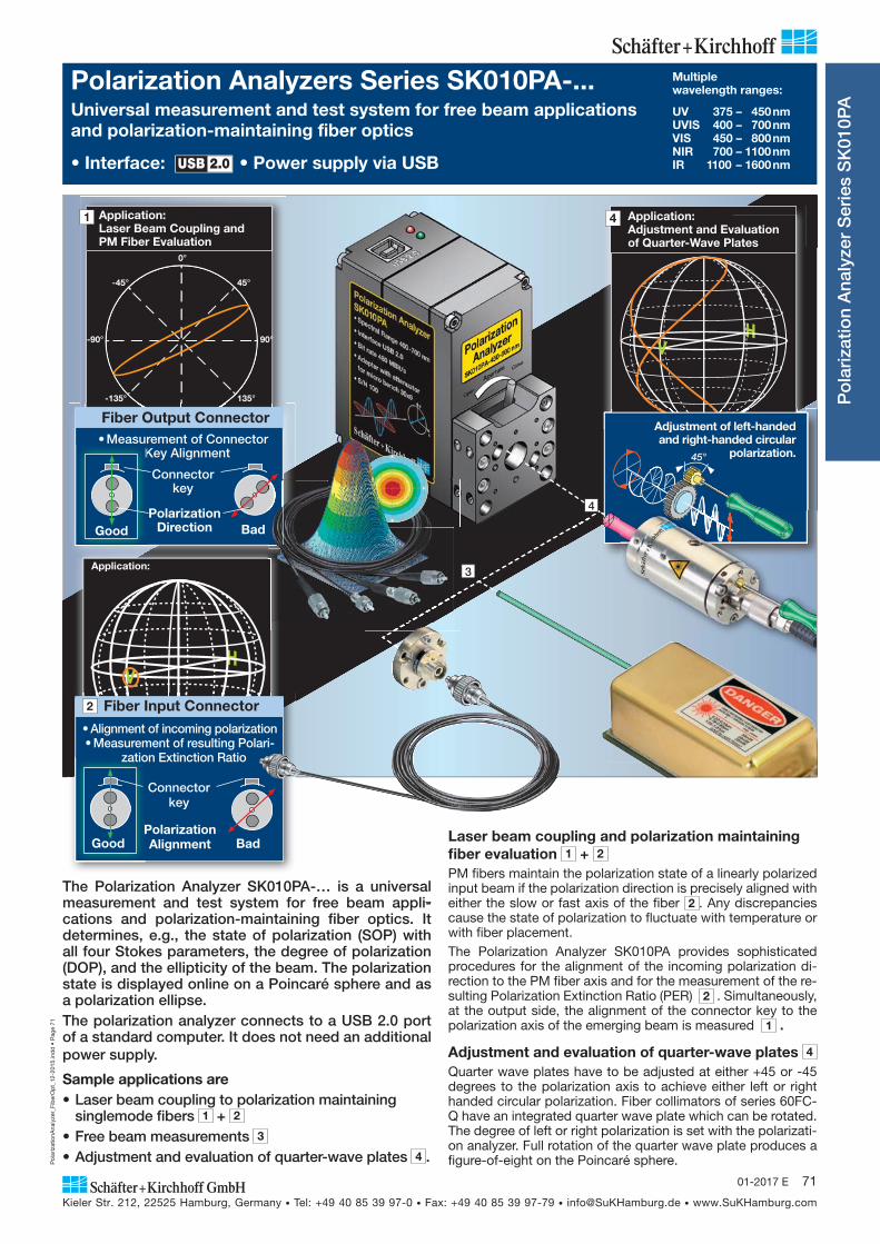
Application:Adjustment and Evaluation of Quarter-Wave Plates
Adjustment of left-handed and right-handed cir cular
polarization.45°
4
4
3
The Polarization Analyzer SK010PA-… is a universal measurement and test system for free beam appli-cations and polarization-maintaining fiber optics. It determines, e.g., the state of polarization (SOP) with all four Stokes parameters, the degree of polarization (DOP), and the ellipticity of the beam. The polariza tion state is displayed online on a Poincaré sphere and as a polarization ellipse.The polarization analyzer connects to a USB 2.0 port of a standard computer. It does not need an additional power supply.
Sample applications are• Laser beam coupling to polarization maintaining
singlemode fibers 1 + 2 • Free beam measurements 3 • Adjustment and evaluation of quarter-wave plates 4 .
Laser beam coupling and polarization maintaining fiber evaluation 1 + 2 PM fibers maintain the polarization state of a linearly polarized input beam if the polarization direction is precisely aligned with either the slow or fast axis of the fiber 2 . Any discrepancies cause the state of polarization to fluctuate with temperature or with fiber placement.The Polarization Analyzer SK010PA provides sophisticated procedures for the alignment of the incoming polarization di-rection to the PM fiber axis and for the measurement of the re-sulting Polarization Extinction Ratio (PER) 2 . Simultaneously, at the output side, the alignment of the connector key to the polarization axis of the emerging beam is measured 1 .
Adjustment and evaluation of quarter-wave plates 4 Quarter wave plates have to be adjusted at either +45 or -45 degrees to the polarization axis to achieve either left or right handed circular polarization. Fiber collimators of series 60FC-Q have an integrated quarter wave plate which can be rotated. The degree of left or right polarization is set with the polarizati-on analyzer. Full rotation of the quarter wave plate produces a figure-of-eight on the Poincaré sphere.
Polarization Analyzers Series SK010PA-... Multiple wavelength ranges:
UV 375 – 450 nmUVIS 400 – 700 nm VIS 450 – 800 nm NIR 700 – 1100 nm IR 1100 – 1600 nm
Universal measurement and test system for free beam applications and polarization-maintaining fiber optics
• Interface: USB 2.0 • Power supply via USB
Po
lari
zatio
n A
naly
zer
Ser
ies
SK
010P
A
-45°
-135°
45°
135°
-180°
0°
-90° 90°
Application:Laser Beam Coupling and PM Fiber Evaluation
Fiber Output Connector• Measurement of Connector
Key AlignmentK
Good Polarization
Direction
Connector key
Bad
1
Application:
Fiber Input Connector
Bad PolarizationAlignment
Connector key
• Alignment of incoming polarization• Measurement of resulting Polari-
zation Extinction Ratio
Good
2
Pol
ariz
atio
nAna
lyze
r_Fi
ber
Op
t_12
-201
5.in
dd
• P
age
72
Kieler Str. 212, 22525 Hamburg, Germany • Tel: +49 40 85 39 97-0 • Fax: +49 40 85 39 97-79 • [email protected] • www.SuKHamburg.com
72 01-2017 E
Po
lari
zatio
n A
naly
zer
Ser
ies
SK
010P
A
Polarizationsanalyzer Series SK010PA-... UV 375 – 450 nmUVIS 400 – 700 nm VIS 450 – 800 nm NIR 700 – 1100 nm IR 1100 – 1600 nm
Multiple Wavelength Ranges 370 – 1600 nm • Interface: USB 2.0 • Power supply via USB
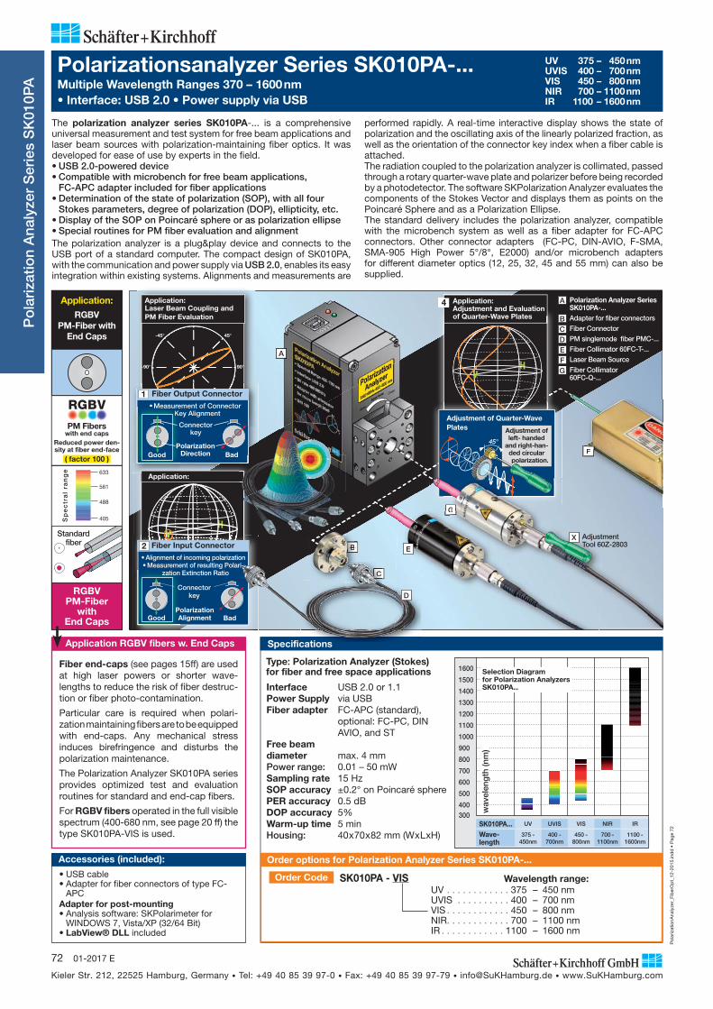
performed rapidly. A real-time interactive display shows the state of polarization and the oscillating axis of the linearly polarized fraction, as well as the orientation of the connector key index when a fiber cable is attached.The radiation coupled to the polarization analyzer is collimated, passed through a rotary quarter-wave plate and polarizer before being recorded by a photodetector. The software SKPolarization Analyzer evaluates the components of the Stokes Vector and displays them as points on the Poincaré Sphere and as a Polarization Ellipse.The standard delivery includes the polarization analyzer, compatible with the microbench system as well as a fiber adapter for FC-APC connectors. Other connector adapters (FC-PC, DIN-AVIO, F-SMA, SMA-905 High Power 5°/8°, E2000) and/or microbench adapters for different diameter optics (12, 25, 32, 45 and 55 mm) can also be supplied.
The polarization analyzer series SK010PA-... is a comprehensive univer sal measurement and test system for free beam applications and laser beam sources with polarization-maintaining fiber optics. It was developed for ease of use by experts in the field.• USB 2.0-powered device• Compatible with microbench for free beam applications,
FC-APC adapter included for fiber applications• Determination of the state of polarization (SOP), with all four
Stokes parameters, degree of polarization (DOP), ellipticity, etc.• Display of the SOP on Poincaré sphere or as polarization ellipse• Special routines for PM fiber evaluation and alignment The polarization analyzer is a plug&play device and connects to the USB port of a standard computer. The compact design of SK010PA, with the communication and power supply via USB 2.0, enables its easy integration within existing systems. Alignments and measurements are
A
Adjustment of left- handed
and right-han-ded circular
polarization.
Adjustment of Quarter-Wave Plates
45°
F
G
Application:Adjustment and Evaluation of Quarter-Wave Plates
4
Fiber end-caps (see pages 15ff) are used at high laser powers or shorter wave-lengths to reduce the risk of fiber destruc-tion or fiber photo-contamination.
Particular care is required when polari-zation maintaining fibers are to be equipped with end-caps. Any mechanical stress induces birefringence and disturbs the polarization maintenance.
The Polarization Analyzer SK010PA series provides optimized test and evaluation routines for standard and end-cap fibers.
For RGBV fibers operated in the full visible spectrum (400-680 nm, see page 20 ff) the type SK010PA-VIS is used.
SK010PA...Wave-length
1600
1500
1400
1300
1200
1100
1000
900
800
700
600
500
400300
wav
elen
gth
(nm
)
UV
375 - 450nm
UVIS
400 - 700nm
VIS
450 - 800nm
NIR
700 - 1100nm
IR
1100 - 1600nm
Selection Diagramfor Polarization Analyzers SK010PA...Interface USB 2.0 or 1.1
Power Supply via USB Fiber adapter FC-APC (standard),
optional: FC-PC, DIN AVIO, and ST
Free beamdiameter max. 4 mmPower range: 0.01 – 50 mWSampling rate 15 HzSOP accuracy ±0.2° on Poincaré spherePER accuracy 0.5 dBDOP accuracy 5%Warm-up time 5 minHousing: 40 x 70 x 82 mm (W x L xH)
Type: Polarization Analyzer (Stokes) for fiber and free space applications
Accessories (included):
• USB cable • Adapter for fiber connectors of type FC-
APCAdapter for post-mounting• Analysis software: SKPolarimeter for
WINDOWS 7, Vista/XP (32/64 Bit)• LabView® DLL included
Order Code SK010PA - VIS UV . . . . . . . . . . . . 375 – 450 nmUVIS . . . . . . . . . . 400 – 700 nm VIS . . . . . . . . . . . . 450 – 800 nm NIR . . . . . . . . . . . . 700 – 1100 nm IR . . . . . . . . . . . . 1100 – 1600 nm
Wavelength range:
Order options for Polarization Analyzer Series SK010PA-...
Application RGBV fibers w. End Caps
405
633
561
488
Sp
ec
tra
l ra
ng
e
Standard fiber
RGBVPM-Fiber
with End Caps
RGBV
PM Fiberswith end caps
Reduced power den-sity at fiber end-face
( factor 100 )
Application:RGBV
PM-Fiber with End Caps
A Polarization Analyzer Series SK010PA-...
B Adapter for fiber connectors
C Fiber Connector
D PM singlemode fiber PMC-...
E Fiber Collimator 60FC-T-...
F Laser Beam Source
G Fiber Collimator 60FC-Q-...
Specifications
-45°
-135°
45°
135°
-180°
0°
-90° 90°
Fiber Output Connector• Measurement of Connector
Key Alignment•Measure
KKKeKKK
Good Polarization
Direction
Connector key
Bad
1
0°
Application: Laser Beam Coupling and PM Fiber Evaluation
Fiber Input Connector
Bad PolarizationAlignment
Connector key
Good
• Alignment of incoming polarization• Measurement of resulting Polari-
zation Extinction Ratio
2
Application:
E
X Adjustment Tool 60Z-2803X
B
C
ti
D
C
BB

Pol
ariz
atio
nAna
lyze
r_Fi
ber
Op
t_12
-201
5.in
dd
• P
age
73
Kieler Str. 212, 22525 Hamburg, Germany • Tel: +49 40 85 39 97-0 • Fax: +49 40 85 39 97-79 • [email protected] • www.SuKHamburg.com
7301-2017 E
The initialization step is performed by calling the DLL, although earlier set-tings from previous mea-surements can also be kept. Continuous measu-rement by the polarizati-on analyzer is started using the next function.Only one function call is required to obtain a mea-
surement point from the constant stream of data produced by the polarization analyzer.There is no restriction on the inclusion of any of the SKPolarimeter software features in a software project produced by or for a customer. This applies to all dialog boxes for the input of different parameters, all graphical displays and the measurement of the extinction ratio of the polarization-maintaining singlemode fibers.
PC or Notebook with USB 2.0
Control, data transfer, voltage supply from PC
Po
lari
zatio
n A
naly
zer
Ser
ies
SK
010P
A
Software applications: PM fiber alignment
Figure 2:Polarization ellipse of PM fiber alignment witha low coherence laser source
B
A
Figure 1:Enhanced measure-ment ad justments for PM fiber axes
Analysis Software SKPolarimeter
Interface: USB 2.0
External programming
PM fiber adjustment with coherent sourcesThe polarization extinction ratio PER of fiber-coupled radiation is the ratio of the optical power coupled to the two main axes of a polarization-maintaining fiber. The polarization analyser is used to optimize the coupling alignment of polarization-maintaining fibers.
• Polarization extinction ratio (PER) measurement• Adjustment support for PM fiber coupling of high and low
coherent sources• Measurement results can be logged and saved• Log file of measurements over a designated time • Calibration of polarization zero phase and resetting to the
original factory settings• Integration of the polarimeter in customizable software with
LabVIEW VI-library and DLL
Only three functions are needed from the SKPolarimeter DLL when integrating the Polariza-tion Analyzer into a customized soft ware application.
PM fiber adjustment with low coherent sourcesThe described PER measurement procedure only applies to a coherent laser source with a degree of polariza tion close to 100%.
For low coherence sources, the light not coupled to the main axis of the fiber contributes to the unpolarized light, which produces an extinction ellipse, see figure 2.
For each measured degree of polarization lower than 80%, an additional dotted polarization ellipse depicts the ratio between linearly polarized light and the sum of circular and unpolarized light. The dotted ellipse becomes smaller for improved alignments between the fiber axes and the linearly polarized fraction of the light.
A When linearly polarized radiation is not coupled exactly to one of the fiber polarization axes, the actual state of polarization fluctuates with temperature and with physical displacement of the fiber.
The measured states of polarization are mapped as a circle on the Poincaré sphere. The center of this circle represents the mean extinction ratio for the particular alignment. For an ideal linear birefringent fiber, the center is on the equator of the sphere. The circle of data points farthest away from the equator represents the lowest extinction ratio that can occur with this particular alignment.
The radius of the circle is a measure of the misalignment angle of the fiber, with smaller radii indicating an improvement in the coupling alignment of the PM fiber. For perfect coupling of linear polarized radiation to one of the main axes of a polarization-maintaining linear birefringent fiber, the circle converges to a single point located on the equator of the Poincaré sphere.
In the software modus PER, a series of measurements are performed and the data logged. For the modulation of the polarization state, the fiber is stressed either by mechanical displacement or heating, which generates a circular cloud of data points on the Poincaré sphere. After acquisition, the data is automatically fitted to a circle.
The aim of the subsequent adjustments is to encourage the convergence of these data points to the center of this circle, by rotating the linear input state of polarization with respect to the fiber main axes.
As an additional aid, the reciprocal distance from the center is displayed continuously by means of a red->green bar plot with either a linear or a logarithmic scale.
B A second measurement of the extinction ratio has been performed.
This reduced radius indicates that the fluctuation of the current state of polarization is reduced.
For the final PER measurement, the mean and minimum PER values are displayed on the linear or logarithmic bar plot.

Pol
ariz
atio
nAna
lyze
r_Fi
ber
Op
t_12
-201
5.in
dd
• P
age
74
Kieler Str. 212, 22525 Hamburg, Germany • Tel: +49 40 85 39 97-0 • Fax: +49 40 85 39 97-79 • [email protected] • www.SuKHamburg.com
74 01-2017 E
Attachments
Adapter for different fiber connectors (see below)
Adapter plateFor attaching beam optical components with Ø 19.5 mm system mount or with Ø 25 mm compatible with microbench systems
Order Code 48MC-MP-19.5 Ø 19.5 mm 48MC-MP-25 Ø 25 mmFurther adapters incl. rods, see page 62f
Rod for mounting to microbench system Order Code 48MC-6-30 30 mm
Configurations Accessories
Adapters for fiber connectors 1 FC-APC (included with delivery)
FC- PC 2 DIN-AVIO PC / APC 3 High Power SMA 905 5°/8°4 F-SMA5 E2000
Further fiber adapters on request.
Standard confi guration with Ø 12 mm fiber collimator
Application: Measurement of laser beampolarization in a free beam setup
ion:ment of laser beamion in a free beam setup
Po
lari
zatio
n A
naly
zer
Ser
ies
SK
010P
A
Micro bench adapters6 Adapter for Ø 12, Ø 25 and
Ø 32 mm optics incl. 4 Rods
Order Code PA-48MC-12 Order Code PA-48MC-25 Order Code PA-48MC-32
7 Adapters for Ø45 and Ø55 mm fiber collimators (Type 60FC-T... or 60FC-L..., page 36ff) incl. 8 Rods
Order Code PA-48MC-45 Order Code PA-48MC-55
PA - FC-4 Order CodeAdapter without optics Connector Type:FC-4 (FC-APC, inclined coupling axis)FC-0 (FC-PC)AVIM-4 (inclined coupling axis)AVIM-0SMA-4 (High Power SMA-905, 8°)SMA-23 (High Power SMA-905, 5°)F-SMA-0E2000-4 (inclined coupling axis)E2000-0
PA - FC-4 - A6.2S - 02 Order Code
Collimating optics: A6.2S f' = 6.2 mm A11 f' = 11 mm
Connector Type: FC-4 (FC-APC, inclined coupling axis)FC-0 (FC-PC)AVIM-4 (inclined coupling axis)AVIM-0SMA-4 (High Power SMA-905 8°)SMA-23 High Power SMA-905 5°)F-SMA-0E2000-4 (inclined coupling axis)E2000-0
Wavelength range: 01 370 – 600 nm 02 600 – 1050 nm 03 1050 – 1550 nm
Adapter with optics
Standard configuration for connecting FC-APC fibersStanconn
USB cable(max. 5 meters)
PC or Notebook with USB 2.0
Control, data transfer, voltage supply from PC
Interface: USB 2.0
Front Side Bottom
26
M2.5
20
20
7026
20
M2.5
2040
82
30/Ø6H7
20
40
Adapter for post-mounting(included in standard delivery).
Other threads available on request.
A
A
108
2026
5
Dimensions
Standard configuration with Ø 55 mm adapter and fiber collimator Standardd conc figuration withw Ø55mm
1 2 3 4 5
6
A C
6
A
A Fiber Collimator B Fiber Collimator C PM singlemode fiber PMC-...
7
C
7
mator
h adapt
C
B
Order Code SK010PA - VIS Wavelength range:UV 370 – 450 nmUVIS 400 – 700 nm VIS 450 – 800 nm NIR 700 – 1100 nm IR 1100 – 1600 nm
Order options for Polarization Analyzer Serie SK010PA-... Adapter without optics
Adapter with optics