Embed Size (px)
Citation preview

Surgical Technique Guide
Polaris™ Deformity System
Thoracolumbar Solutions
Trivium® Derotation System

2 Polaris™ Deformity System and Trivium® Derotation System—Surgical Technique Guide

Polaris™ Deformity System and Trivium® Derotation System—Surgical Technique Guide 3
TABLE OF CONTENTS
Hook Site Preparation and Insertion 4
Screw Placement 9
Screw Selection and Insertion 10
Rod Selection and Application 14
Rod Reduction 15
In Situ Contouring 18
Distraction and Compression 19
Cross Connector Application 20
Rod Rotation 21
Direct Vertebral Column Technique 23
Iliac Fixation Surgical Technique 26
Provisional and Final Tightening 28
Closure, Postoperative and Implant Removal 29
Kit Contents 30
Instruments and Implants: 5.5mm Deformity Implants 46
Instruments and Implants: 5.5mm Deformity Instruments 50
Instruments and Implants: 6.35mm Deformity Implants 55
Instruments and Implants: 6.35mm Deformity Instruments 59
Important Information on the Polaris Deformity System and 63 Trivium Derotation System
Zimmer Biomet Spine does not practice medicine. This technique was developed in conjunction
with health care professionals. This document is intended for surgeons and is not intended for
laypersons. Each surgeon should exercise his or her own independent judgment in the diagnosis
and treatment of an individual patient, and this information does not purport to replace the
comprehensive training surgeons have received. As with all surgical procedures, the technique
used in each case will depend on the surgeon’s medical judgment as the best treatment for each
patient. Results will vary based on health, weight, activity and other variables. Not all patients
are candidates for this product and/or procedure.

4 Polaris™ Deformity System and Trivium® Derotation System—Surgical Technique Guide
Hook starters are used to prepare the hook implant site. Various starters match the hook style desired.
HOOK SITE PREPARATION AND INSERTION
PEDICLE HOOK
The Polaris System pedicle hook is designed to obtain purchase in the thoracic spine from the tenth thoracic vertebra to the first thoracic vertebra. These hooks are placed in an up-going fashion, allowing the bifurcated blade of the hook to engage the pedicle at that level.

Polaris™ Deformity System and Trivium® Derotation System—Surgical Technique Guide 5
STEP 1
• The pedicle hook site is prepared by using a quarter-inch osteotome.
• Two cuts are made on the inferior facet of the level to be instrumented. A superior-to-inferior cut is made at the lateral margin of the ligamentum flavum and is directed 2mm–3mm proximally. The second cut with a quarter-inch osteotome is performed in a transverse plane from the lateral edge of the facet to the medial cut. Approximately 6mm of inferior facet should remain when measured from the base of the transverse process.
• The osteotomized bone is removed and the facet cartilage is curetted.
• The thoracic pedicle hook site may then be prepared with the pedicle hook starter. Caution should be used to prevent medial penetration of the canal with this instrument. The appropriate sized pedicle hook can be placed in a hook holder with a hook impactor and gently tapped into a seated position.
• The angled hook holder is cannulated to align the plug starter.
• The hook impactor incorporates a strike plate and may be gently tapped to allow for better hook control and to securely seat the hook onto the pedicle.
Hook is placed up-going on the pedicle
The pedicle hook starter is used to prepare the site

6 Polaris™ Deformity System and Trivium® Derotation System—Surgical Technique Guide
LAMINAR HOOKS
In general, laminar hooks are placed by removing an appropriate amount of ligamentum flavum and surrounding bone to provide safe passage of the hook into the spinal canal in an infralaminar or supralaminar position depending upon the appropriate level. Care should be taken to note that the bone encompassed by the hook completely fills the throat of the hook, thus preventing unnecessary penetration of the blade into the canal.
Polaris thoracic and lumbar laminar hooks may be placed in a supralaminar or infralaminar position depending on the location of the spine. A wide selection of Polaris laminar hooks are available for use in different locations. Offset down-going laminar hooks can be used at the top of the thoracic construct where transverse processes are small.
HOOK SITE PREPARATION AND INSERTION (continued)
Narrow blade, angled laminar hooks
Wide and narrow blades, laminar hooks
STEP 1, OPTION A
Hook Selection
• When placing hooks down-going, left hooks are used on the right side and vice versa. This allows the tulip to be in-line with the other hooks in place.
Standard laminar hook placed up-going
Offset hooks Reduced throat laminar hook
Standard laminar hook
Extended body laminar hook
Standard laminar hook

Polaris™ Deformity System and Trivium® Derotation System—Surgical Technique Guide 7
STEP 1, OPTION B
• In the lower lumbar spine, larger offset laminar hooks are placed in an up-going fashion in order to maintain co-linearity of the saddles of the implants.
• In some situations, particularly when a sub-adjacent pedicle screw is in place, the offset laminar hook is ideal for placement in the transverse process location.
STEP 1, OPTION C
• Reduced laminar hooks are placed in the thoracic spine in a down-going fashion at the end of the concavity of the curve or in the rigid segment. These hooks prevent unnecessary crowding of the blade of the hook into the spinal canal.
Offset laminar hook placed down-going Reduced laminar hook placed down-going

8 Polaris™ Deformity System and Trivium® Derotation System—Surgical Technique Guide
STEP 1, OPTION D
• Extended body laminar hooks are best used in a down-going fashion in the mid-lumbar spine in order to maintain the appropriate height of the rod construct proximally and distally with the other implants.
Extended body hook placed down-going
HOOK SITE PREPARATION AND INSERTION (continued)

Polaris™ Deformity System and Trivium® Derotation System—Surgical Technique Guide 9
STEP 2
• The Polaris System pedicle screws are placed within those vertebral bodies determined by the surgeon to be appropriate in size and location. Pre-operative and intra-operative imaging is valuable to assess the size of the pedicle and its ideal starting point. Image guidance may offer information about screw trajectory for the pedicle screw. Pedicle screw placement may be performed in several ways according to surgeon experience and preference.
• The Polaris System provides a full line of options for pedicle screw fixation with fixed and multi-axial screws with diameters ranging from 4.0mm to 8.5mm and lengths ranging 20mm to 55mm. Pedicle screws are inserted using established anatomical and fluoroscopic landmarks. Various pedicle finders, probes and taps are available to assist the surgeon in development, probing and measurements of the pedicle.
Note: All implants are available in stainless steel.
Self-tapping screws are available in several diameters and lengths. The appropriate screw length is determined by using the depth markings on the pedicle probe, or by feeling the anterior wall with the sound and marking it with a hemostat.
• Attach the selected screw driver to the chosen quick-connect handle by pulling back on the plunger at the base of the quick connect mechanism, inserting the shaft and releasing the plunger to lock the shaft in place.
• Hold the screw by the screw shaft and load the screw onto the tip of the fixed or multi-axial screw driver.
Multi-axial screw offering
Fixed screw offeringThe thoracic probe is used to prepare the pedicle hole
SCREW PLACEMENT

10 Polaris™ Deformity System and Trivium® Derotation System—Surgical Technique Guide
SCREW SELECTION AND INSERTION
STEP 3, OPTION A
Standard Multi-axial Screw Inserter
• Use with the following screws:
• Polaris 5.5 multi-axial screws
• Polaris 5.5 iliac multi-axial screws
• Polaris 6.35 Ti 7.5mm and 8.5mm diameter screws
• Polaris 6.35 stainless steel multi-axial screws
• Polaris 6.35 iliac multi-axial screws
• To use the standard multi-axial screw inserter, ensure the male pentalobe at the distal tip of the driver is fully seated within the female pentalobe located at the top of the screw shaft.
• Slide the outer sleeve of the inserter down into the seat of the screw, and then turn the round, knurled grip in a clockwise direction to thread the outer shaft into the seat.
Multi-axial screw inserter
• Turn until tight and confirm that the screw is straight and secure in the driver. If it is not, remove the screw from the driver and repeat steps above. The screw is advanced into the pedicle to the desired depth.
• During insertion, guide the driver by holding the black sleeve on the shaft of the instrument.
• The driver is disengaged from the screw by turning the round, knurled grip in a counterclockwise direction, pulling the outer sleeve up and lifting the driver from the screw.
Note: Polaris™ 5.5 Titanium Spinal System 4mm diameter screws are not for use with cobalt chrome alloy rods.
Optional: Multi-axial screw driver with two modes: LOCKING and NON-LOCKING capacity. (This must be ordered separately by the sales representative).

Polaris™ Deformity System and Trivium® Derotation System—Surgical Technique Guide 11
• Finally, pull the outer sleeve up and lift the driver from the screw.
• If the surgeon prefers the NON-LOCKING setting, ensure the knob on the knurled grip is rotated so that the arrow points to the “OFF” icon.
• Place the tip of the inserter into the seat of the screw, and then turn the knurled grip in a clockwise direction to thread the outer shaft into the seat.
• Turn until tight and confirm that the screw is straight and secure in the driver. The screw is advanced into the pedicle to the desired depth. During insertion, guide the driver by holding the black sleeve on the shaft of the instrument.
• The driver is disengaged from the screw by turning the round, knurled grip in a counterclockwise direction, pulling the outer sleeve up and lifting from the screw.
STEP 3, OPTION A (continued)
• If using the LOCKING setting, ensure the knob located on the knurled grip is rotated so that the arrow points to the “ON” icon.
• Place the tip of the inserter into the seat of the screw, and then turn the knurled grip in a clockwise direction to thread the outer shaft into the seat. The driver will begin to “ratchet” when it is almost fully engaged. It will stop ratcheting when the screw is fully loaded.
• Confirm the screw is straight and secure in the driver. The screw is advanced into the pedicle to the desired depth. During insertion, guide the driver by holding the black sleeve on the shaft of the instrument.
• The driver is disengaged from the screw by rotating the knob to point to the “OFF” icon, then unthreading the outer sleeve from the screw. The surgeon can also push and hold the button located on the opposite side of the knob.
Load the screw driver

12 Polaris™ Deformity System and Trivium® Derotation System—Surgical Technique Guide
Insert the screw into the pedicle at the appropriate angle and depth
STEP 3, OPTION B
Polaris 5.5 Fixed Screw Inserter
• To use the standard fixed screw inserter, ensure the male blunt tip at the distal end of the driver is fully seated within the seat of the screw shaft.
• Slide the outer sleeve of the inserter down into the seat of the screw, and then turn the round, knurled grip in a clockwise direction to thread the outer shaft into the seat.
• Turn until tight and confirm that the screw is straight and secure in the driver. If it is not, remove the screw from the driver and repeat steps above. The screw is advanced into the pedicle to the desired depth.
• During insertion, guide the driver by holding the black sleeve on the shaft of the instrument.
• The driver is disengaged from the screw by turning the round, knurled grip in a counterclockwise direction, pulling the outer sleeve up and lifting the driver from the screw.
STEP 3, OPTION C
Polaris 6.35 System Multi-axial Screw Driver and Fixed Screw Inserter
• When using the multi-axial screw driver, first ensure that the knurled T is at the top of the driver shaft. This prevents the outer shaft from prematurely dropping into the screw head.
• Next, hold the screw by the screw shaft and load the screw onto the tip of the driver. Ensure that the male hex end at the top of the screw shaft is fully seated into the female hex of the driver.
• Then turn the knurled T in a clockwise direction to thread the outer shaft into the seat. Confirm the screw is straight and secure in the driver.
• The screw is advanced into the pedicle to the desired depth. During insertion, guide the driver by holding the blue sleeve on the shaft of the instrument.
• The driver is disengaged from the screw by rotating the knurled T in a counterclockwise direction, and then lifting the driver from the screw.
SCREW SELECTION AND INSERTION (continued)

Polaris™ Deformity System and Trivium® Derotation System—Surgical Technique Guide 13
STEP 4
• The bone planer is used to remove bone that may be hindering engagement of instruments onto the screw, before or after the rod is introduced (e.g., base of thoracic transverse process or lamina.)
Bone planer is used to remove small amounts of bone around screw to help facilitate instrument engagement
Inner Blocking Ring
• Fixed head screws are inserted using the fixed screw driver. Attach the fixed screw driver shaft to the quick-connect handle.
• Ensure that the knurled T is at the top of the driver shaft. This prevents the outer shaft from prematurely dropping into the screw head.
• Next, hold the screw by the screw shaft and load the screw into the tip of the fixed driver.
• Then, turn the knurled T in a clockwise direction to thread the outer shaft into the seat. Confirm the screw is secure in the driver.
• The screw is advanced into the pedicle to the desired depth. The fixed driver is disengaged from the screw by rotating the knurled T in a counterclockwise direction, and then lifting the driver from the screw.

14 Polaris™ Deformity System and Trivium® Derotation System—Surgical Technique Guide
STEP 5
• Polaris rods are offered in titanium alloy, commercially pure titanium and cobalt chrome alloy for use with the titanium alloy components.
• Stainless steel components should never be used with components made of titanium alloy, commercially pure titanium, or cobalt chrome alloy, per the package insert.
• The variety of stiffness and strength combinations of rods allow the surgeon to tailor the construct to the surgeon’s preference according to the needs of the patient.
• Commercially pure titanium and titanium alloy have similar stiffness properties. However, commercially pure titanium is a softer material and is easier to bend than titanium alloy. If a stiffer rod is preferred, cobalt chrome rods are offered in an extra-hard tensile strength.
• A 5.5mm diameter cobalt chrome alloy rod enables the construct to behave with the similar strength and stiffness compared to a 5.5mm diameter stainless steel rod.
Ti alloy
Cobalt chrome alloy
Stainless steel CP Ti
Rod template
ROD SELECTION AND APPLICATION
• The bending properties of cobalt chrome alloy rods continue to harden as in situ bending occurs repeatedly. As with any metal, rods should be bent with caution and minimally to prevent fracture and fatigue.
• The use of cobalt chrome alloy rods with titanium implants (screws, hooks and plugs) maintains imaging capabilities. Cobalt chrome alloy rods are only to be used with titanium implants and are never used with stainless steel implants.
• Stainless steel rods are for use with stainless steel implants only. Zimmer Biomet Spine offers three tensile strengths in order for the surgeon to select the appropriate rigidity desired based on patient needs.
• The rods include two etched longitudinal lines along the length of the rod to help determine the correct plane and reference when bending and inserting the rod. The etched lines also aid in rod rotation. The rods incorporate two hex ends for additional options with rod rotation.
• A malleable rod template is available in order to aid with rod measurement and bending prior to rod insertion.

Polaris™ Deformity System and Trivium® Derotation System—Surgical Technique Guide 15
STEP 7, OPTION A
Rod Pusher
• The straight rod pusher is available with bent tip or straight tip to allow for optimum visualization of the rod persuasion into the tulip of the screw or hook. The pushers can be tapped with a mallet to facilitate rod placement.
Straight rod pusher used to persuade the rod into the tulip and facilitate plug insertion
Rod pusher encompassing the screw to seat the rod and facilitate plug insertion
STEP 6
• The rod is inserted into the proximal hook or screw. It is often helpful to place a plug in the most proximal saddle prior to rod placement in order to facilitate proximal fixation of the rod.
• The rod can then be reduced to the hooks and screws with a variety of options: rod pusher, rod manipulator, rod rocker or the rod reducer.
ROD REDUCTION

16 Polaris™ Deformity System and Trivium® Derotation System—Surgical Technique Guide
STEP 7, OPTION B
Rod Manipulator
• The rod manipulator is used to persuade the rod into the tulip and can move the rod cephalad/caudal and medial/lateral.
• First, place the manipulator on the rod, then turn the handle 90° clockwise to lock the instrument to the rod. Push, pull or translate the rod into the seat.
Step 1—Load the instrument onto the rod
Step 2—Turn the instrument handle 90° and engage the rod
Step 3—Push the rod into screw seat to facilitate plug insertion
• Provisionally place the plug into the tulip, turn the handle 90° counterclockwise to release the manipulator and lift up.
Note: Be cautious of bone that may be underneath the instrument that may hinder the application and release of the instrument. If this occurs, use a different rod reduction option or remove the bone with the bone planer.
ROD REDUCTION (continued)

Polaris™ Deformity System and Trivium® Derotation System—Surgical Technique Guide 17
Step 3—Push the rod into screw seat to facilitate plug insertion
Step 2—Squeeze handle to advance the middle and outer sleeves
Step 1—Place onto the screw
STEP 7, OPTION C
Rod Persuader
• The rod persuader offers the surgeon a controlled and powerful means in which to reduce the rod into the seat. This can be used for standard screws and reduction screws.
• Place the persuader over top of the screw seat until the blocking ring rests on the top of the screw. This ensures the persuader is in proper position.
• Begin to squeeze the blue handle to advance the middle and outer sleeves. Once the middle sleeve passes the inner blocking ring, the persuader will grab the screw seat connecting into the dimples of the seat. Continue to squeeze the handle to seat the rod.
• The plug starter will fit through the cannulated portion of the persuader, allowing for plug application with the persuader in place. To release the persuader, press the trigger located underneath the handle. Once released, the persuader may then be removed from the screw seat.
Note: Each rod reduction instrument allows for plug application.
STEP 8
• Once the rod is reduced, the spine can be corrected with rod rotation, in situ bending, or use of cables and wires to translate the spine to the rod. Once the plugs have been provisionally tightened and the construct confirmed, the contralateral rod is placed in the standard fashion, thus providing further fixation. Plugs are finally tightened using the torque wrench and counter torque wrench.
• If using cables, refer to the Lentur™ Cable System Surgical Technique (BSP216543L).

18 Polaris™ Deformity System and Trivium® Derotation System—Surgical Technique Guide
STEP 9
• In situ contouring may be performed with in situ and/or coronal benders prior to final torquing. In general, the in situ benders are used to improve or adjust kyphosis and lordosis, and coronal benders are used to reduce coronal plane deformity.
Coronal plane correctionSagittal plane correction
IN SITU CONTOURING
Polaris™ Deformity System and Trivium® Derotation System—Surgical Technique Guide 19
DISTRACTION AND COMPRESSION
STEP 10
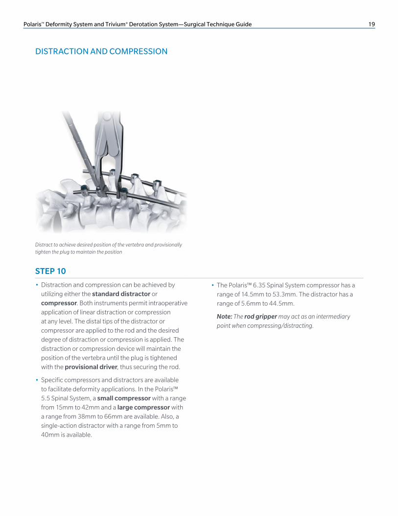
• Distraction and compression can be achieved by utilizing either the standard distractor or compressor. Both instruments permit intraoperative application of linear distraction or compression at any level. The distal tips of the distractor or compressor are applied to the rod and the desired degree of distraction or compression is applied. The distraction or compression device will maintain the position of the vertebra until the plug is tightened with the provisional driver, thus securing the rod.
• Specific compressors and distractors are available to facilitate deformity applications. In the Polaris™ 5.5 Spinal System, a Small Compressor with a range from 15mm to 42mm and a large compressor with a range from 38mm to 66mm are available. Also, a single-action distractor with a range from 5mm to 40mm is available.
Distract to achieve desired position of the vertebra and provisionally tighten the plug to maintain the position
• The Polaris™ 6.35 Spinal System compressor has a range of 14.5mm to 53.3mm. The distractor has a range of 5.6mm to 44.5mm.
Note: The rod gripper may act as an intermediary point when compressing/distracting.
20 Polaris™ Deformity System and Trivium® Derotation System—Surgical Technique Guide
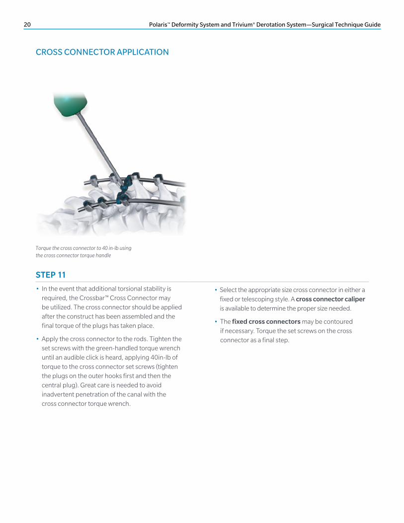
CROSS CONNECTOR APPLICATION
Torque the cross connector to 40 in-lb using the cross connector torque handle
STEP 11
• In the event that additional torsional stability is required, the Crossbar™ Cross Connector may be utilized. The cross connector should be applied after the construct has been assembled and the final torque of the plugs has taken place.
• Apply the cross connector to the rods. Tighten the set screws with the green-handled torque wrench until an audible click is heard, applying 40in-lb of torque to the cross connector set screws (tighten the plugs on the outer hooks first and then the central plug). Great care is needed to avoid inadvertent penetration of the canal with the cross connector torque wrench.
• Select the appropriate size cross connector in either a fixed or telescoping style. A cross connector caliper is available to determine the proper size needed.
• The fixed cross connectors may be contoured if necessary. Torque the set screws on the cross connector as a final step.

Polaris™ Deformity System and Trivium® Derotation System—Surgical Technique Guide 21
ROD ROTATION
Hex end wrench attached to hex end on rods used to facilitate rotation
STEP 12
• With plugs loosely engaged, the rods are simultaneously rotated into the desired sagittal profile to obtain three-dimensional deformity correction. This is verified by the exact dorsal orientation of the longitudinal rod marker lines. Rotation of the rod can be done in lesser curves with the hex end wrenches engaging the hexagonal rod end.
• A greater force can be applied using the rod rotators for larger curves. Place the distal tip of the rotators onto the rod and squeeze the handle until firmly gripping the rod. Rotate the rod to the desired position. To release the rotators, lift the trigger release.

22 Polaris™ Deformity System and Trivium® Derotation System—Surgical Technique Guide
STEP 13, OPTION A
Segmental Translation
• Reduction screws or extended screws are very useful during challenging cases and offer the surgeon a variety of techniques to correct the spine.
• Reduction screws are used for segmental translation of the lumbar spine. The rod is secured in the S1 screw to act as a firm anchor. The rod is then slowly reduced by inserting the plug and tightening gradually from L1–L5. The spine is translated to the rods, thus correcting the coronal or sagittal plane.
• Once the Helical Flange® plugs are inserted to the appropriate depth below the break off tab, the plugs must be torqued with the chosen torque wrench and counter-torque stabilizer.
STEP 13, OPTION B
Kyphosis Correction
• Reduction screws are used during kyphosis cases in order to reduce the spine to the correct sagittal alignment. The rod is slowly reduced into the screw tulip using the reduction instruments and Helical Flange plug.
• Once the Helical Flange plugs are inserted to the appropriate depth below the break off tab, the plugs must be torqued with the chosen torque wrench and counter torque stabilizer.
ROD ROTATION (continued)

Polaris™ Deformity System and Trivium® Derotation System—Surgical Technique Guide 23
Hex end wrench is used to rotate the rods
Fixed screws are placed in clusters of 5–8 about the apices of the lumbar and thoracic curves
DIRECT VERTEBRAL COLUMN MANIPULATION TECHNIQUE
STEP 1
• While rod rotation and/or in situ contouring address the bidimensional or global deformity of the spine, derotation addresses the third dimension of the axial plane.
• At this point in the surgical procedure, a near complete two-dimensional correction should have been achieved. Derotation of the spine can be accomplished by use of fixed pedicle screws at selected levels. Common areas where derotation is of benefit are the apical and end vertebra.
• This is an excellent method for reducing the rotational deformity of the spine. Structural curves with a true, stiff axial plane malrotation are targeted by placing between 5–8 fixed head pedicle screws.
• In order to derotate segments of the spine, it is important that there be appropriate fixation points on the remaining segments of the spine against which to derotate. Best results are achieved by aligning and then linking opposing axial plane corrective forces. An example would be a right thoracic against left thoracolumbar in a classic double-major pattern.
• In a double thoracic curve, the cephalad and caudad foundations oppose the corrective axial force. An extra level past the measured Cobb “end” vertebra may need to be included in a large, stiff curve.
• A stiff upper thoracic secondary curve provides a stronger opposing axial force than a thoracolumbar junction compensatory curve.
Global correction has been performed

24 Polaris™ Deformity System and Trivium® Derotation System—Surgical Technique Guide
STEP 2
• Derotation levers are engaged on the various clusters. Levers are aligned within each cluster and handle linkage rods are placed in the first hole in the handles.
• A comb is then engaged from above onto the handle linkage rods. All 5–8 screws in a cluster are thus linked to provide a uniform axial plane corrective force distributed through multiple screws minimizing the chance of screw ploughing.
• Two clusters in a double-major scoliosis are simultaneously slowly derotated, three in a single thoracic or triple major.
Handle linkage rods are attached through the handle of each cluster
Attach the comb to connect the lumbar and thoracic curve clusters respectively
Derotation tubes are attached to the fixed screws in the apical clusters
DIRECT VERTEBRAL COLUMN MANIPULATION TECHNIQUE (continued)
Comb connecting to handle linkage rods
Derotate the spine by manipulating the clusters
The spine is now corrected
ClusterAlignment Rod
Cluster alignment is to hold correction in place
• Spine is derotated in all three planes. Once the desired derotation is achieved, Cluster alignment rods placed through various handle slots on both sides hold the axial plane correction.
• It is important to monitor neurologic function with real-time spinal cord electrophysiologic testing throughout this maneuver, especially with larger curves.
Polaris™ Deformity System and Trivium® Derotation System—Surgical Technique Guide 25
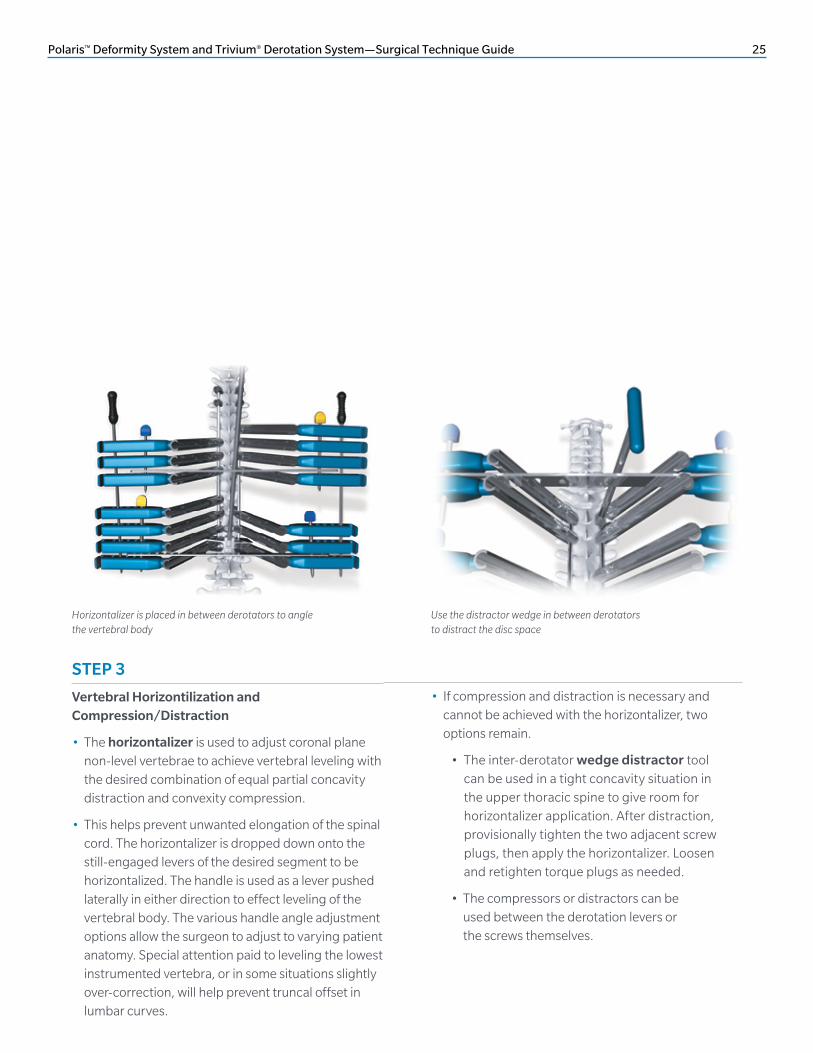
Horizontalizer is placed in between derotators to angle the vertebral body
• If compression and distraction is necessary and cannot be achieved with the horizontalizer, two options remain.
• The inter-derotator wedge distractor tool can be used in a tight concavity situation in the upper thoracic spine to give room for horizontalizer application. After distraction, provisionally tighten the two adjacent screw plugs, then apply the horizontalizer. Loosen and retighten torque plugs as needed.
• The compressors or distractors can be used between the derotation levers or the screws themselves.
Use the distractor wedge in between derotators to distract the disc space
STEP 3
Vertebral Horizontilization and Compression/Distraction
• The horizontalizer is used to adjust coronal plane non-level vertebrae to achieve vertebral leveling with the desired combination of equal partial concavity distraction and convexity compression.
• This helps prevent unwanted elongation of the spinal cord. The horizontalizer is dropped down onto the still-engaged levers of the desired segment to be horizontalized. The handle is used as a lever pushed laterally in either direction to effect leveling of the vertebral body. The various handle angle adjustment options allow the surgeon to adjust to varying patient anatomy. Special attention paid to leveling the lowest instrumented vertebra, or in some situations slightly over-correction, will help prevent truncal offset in lumbar curves.

26 Polaris™ Deformity System and Trivium® Derotation System—Surgical Technique Guide
STEP 1
• In some instances, such as neuromuscular scoliosis with pelvic obliquity or when additional fixation is necessary to load share at the lumbosacral junction, iliac fixation may be valuable.
• The iliac wing and posterior superior iliac spine are exposed by the surgeon’s preferred method. The iliac wing is typically exposed enough to orient the path of the iliac screw to ensure that the iliac cortex is not violated during placement of the iliac screw.
• Place the pedicle probe down between the iliac tables in a manner that places the path about 1cm to 1.5cm above the greater sciatic notch.
Insert the multi-axial screw into the pelvis
• The pedicle probe or reamer probe may be used to start the hole, but may not extend to the entire length of the iliac screw chosen.
• This can be confirmed with fluoroscopy of the pelvis or by tactile feedback, depending on the surgeon’s standard protocol. In general, it is best to place the largest screw diameter possible.
• The screw is placed after the inner and outer tables are palpated with a pedicle sound and the iliac walls and floors are noted to be intact. It is recommended to notch the iliac wing around the screw head to sink the screw head to prevent prominence.
ILIAC FIXATION SURGICAL TECHNIQUE

Polaris™ Deformity System and Trivium® Derotation System—Surgical Technique Guide 27
Lateral connector loaded onto rod connected to the iliac screw
STEP 2
• Preload the lateral connector onto the longitudinal rod. The post of the lateral connector may be cut and contoured as deemed necessary.
• A lateral connector may also be used at points along the construct to connect to a screw that may be lateral and out of line with the pedicle screw above and below this point.

28 Polaris™ Deformity System and Trivium® Derotation System—Surgical Technique Guide
• Finally, tighten the plug at the lateral connector/longitudinal rod interface.
• All plugs must be final tightened with the torque wrench in combination with the counter-torque wrench.
• In tightening the plugs, first secure the plugs along the longitudinal rod.
• Then secure the plug where it mates with the post of the lateral connector within the lateral or iliac screw.
PROVISIONAL AND FINAL TIGHTENING

Polaris™ Deformity System and Trivium® Derotation System—Surgical Technique Guide 29
CLOSURE
• After implantation of the Polaris Spinal System is complete, closure is performed in layers according to standard protocol.
IMPLANT REMOVAL
• Removal of the Polaris Spinal System is performed by reversing the order of the implant procedure. The T-handle attached to the plug driver, in combination with the counter torque, must be used first to remove the plugs.
POSTOPERATIVE CARE
• To enhance recovery following implantation of the Polaris Spinal System, the patient should be mobilized after a few days.
• A TSLO brace may be used postoperatively to decrease excessive mobility.
• Walking-intensive activities should be restricted until otherwise advised by the surgeon.
• Postoperative radiographs should be taken periodically and reviewed to ensure fixation stability.
CLOSURE, POSTOPERATIVE CARE AND IMPLANT REMOVAL

30 Polaris™ Deformity System and Trivium® Derotation System—Surgical Technique Guide
KIT CONTENTS
DESCRIPTION PART NUMBER
Standard Helical Flange Plug 14-505100
Derotation Helical Flange Plug 14-505110
Med SST Rod with Hex, ø5.5mm × 510mm 14-505402
Hard SST Rod with Hex, ø5.5mm × 510mm 14-505406
Extra Hard SST Rod with Hex, ø5.5mm × 510mm
14-505410
Lateral Connector, 25mm 14-505120
Lateral Connector, 35mm 14-505122
Lateral Connector, 50mm 14-505124
Lateral Connector, 75mm 14-505126
Fixed Cross Connector, 12mm 14-505142
Fixed Cross Connector, 14mm 14 -505143
Fixed Cross Connector, 16mm 5006760
Fixed Cross Connector, 18mm 5006761
Fixed Cross Connector, 20mm 5006762
Fixed Cross Connector, 22mm 5006763
Fixed Cross Connector, 24mm 5006764
Fixed Screw, ø4.75mm × 20mm 14-504220
Fixed Screw, ø4.75mm × 25mm 14-504225
Fixed Screw, ø4.75mm × 30mm 14-504230
Fixed Screw, ø4.75mm × 35mm 14-504235
Fixed Screw, ø4.75mm × 40mm 14-504240
Fixed Screw, ø4.75mm × 45mm 14-504245
Fixed Screw, ø5.5mm × 20mm 14-504320
Fixed Screw, ø5.5mm × 25mm 14-504325
Fixed Screw, ø5.5mm × 30mm 14-504330
Fixed Screw, ø5.5mm × 35mm 14-504335
Fixed Screw, ø5.5mm × 40mm 14-504340
Fixed Screw, ø5.5mm × 45mm 14-504345
Fixed Screw, ø5.5mm × 50mm 14-504350
Fixed Screw, ø5.5mm × 55mm 14-504355
Polaris 5.5 SST Deformity Screw Implant Kit 14-509650
DESCRIPTION PART NUMBER
Fixed Screw, ø6.5mm × 30mm 14-504430
Fixed Screw, ø6.5mm × 35mm 14-504435
Fixed Screw, ø6.5mm × 40mm 14-504440
Fixed Screw, ø6.5mm × 45mm 14-504445
Fixed Screw, ø6.5mm × 50mm 14-504450
Fixed Screw, ø6.5mm × 55mm 14-504455
Fixed Screw, ø7.5mm × 30mm 14-504530
Fixed Screw, ø7.5mm × 35mm 14-504535
Fixed Screw, ø7.5mm × 40mm 14-504540
Fixed Screw, ø7.5mm × 45mm 14-504545
Fixed Screw, ø7.5mm × 50mm 14-504550
Fixed Screw, ø7.5mm × 55mm 14-504555
Fixed Screw, ø8.5mm × 30mm 14-504630
Fixed Screw, ø8.5mm × 35mm 14-504635
Fixed Screw, ø8.5mm × 40mm 14-504640
Fixed Screw, ø8.5mm × 45mm 14-504645
Fixed Screw, ø8.5mm × 50mm 14-504650
Fixed Screw, ø8.5mm × 55mm 14-504655

Polaris™ Deformity System and Trivium® Derotation System—Surgical Technique Guide 31
DESCRIPTION PART NUMBER
Pedicle Hook, Small, 6mm 14-505500
Pedicle Hook, Medium, 7.5mm 14-505502
Pedicle Hook, Large, 9mm 14-505504
Left Angled Hook, Small, 6mm 14-505506
Right Angled Hook, Small, 6mm 14-505508
Left Angled Hook, Medium, 7.5mm 14-505510
Right Angled Hook, Medium, 7.5mm 14-505512
Left Angled Hook, Large, 9mm 14-505514
Right Angled Hook, Large, 9mm 14-505516
Narrow Laminar Hook, Small, 6mm 14-505524
Narrow Laminar Hook, Medium, 7.5mm 14-505526
Narrow Laminar Hook, Large, 9mm 14-505528
Narrow Reduced Laminar Hook, Small, 6mm 14-505530
Narrow Reduced Laminar Hook, Medium, 7.5mm
14-505532
Narrow Reduced Laminar Hook, Large, 9mm 14-505534
Wide Laminar Hook, Small, 6mm 14-505518
Wide Laminar Hook, Medium, 7.5mm 14-505520
Wide Laminar Hook, Large, 9mm 14-505522
Left Offset Hook, Small, 6mm 14-505536
Right Offset Hook, Small, 6mm 14-505538
Left Offset Hook, Medium, 7.5mm 14-505540
Right Offset Hook, Medium, 7.5mm 14-505542
Left Offset Hook, Large, 9mm 14-505544
Right Offset Hook, Large, 9mm 14-505546
Angled Blade Hook, Small, 6mm 14-505548
Angled Blade Hook, Medium, 7.5mm 14-505550
Angled Blade Hook, Large, 9mm 14-505552
Extended Hook, Small, 6mm 14-505554
Extended Hook, Medium, 7.5mm 14-505556
Extended Hook, Large, 9mm 14-505558
DESCRIPTION PART NUBMER
Helical Flange SST Plug 14-505100
Multi-axial SST Screw, ø5.5mm × 20mm 14-502320
Multi-axial SST Screw, ø5.5mm × 25mm 14-502325
Multi-axial SST Screw, ø5.5mm × 30mm 14-502330
Multi-axial SST Screw, ø5.5mm × 35mm 14-502335
Multi-axial SST Screw, ø5.5mm × 40mm 14-502340
Multi-axial SST Screw, ø5.5mm × 45mm 14-502345
Multi-axial SST Screw, ø5.5mm × 50mm 14-502350
Multi-axial SST Screw, ø5.5mm × 55mm 14-502355
Multi-axial SST Screw, ø6.5mm × 30mm 14-502430
Multi-axial SST Screw, ø6.5mm × 35mm 14-502435
Multi-axial SST Screw, ø6.5mm × 40mm 14-502440
Multi-axial SST Screw, ø6.5mm × 45mm 14-502445
Multi-axial SST Screw, ø6.5mm × 50mm 14-502450
Multi-axial SST Screw, ø6.5mm × 55mm 14-502455
Multi-axial SST Screw, ø7.5mm × 30mm 14-502530
Multi-axial SST Screw, ø7.5mm × 35mm 14-502535
Multi-axial SST Screw, ø7.5mm × 40mm 14-502540
Multi-axial SST Screw, ø7.5mm × 45mm 14-502545
Multi-axial SST Screw, ø7.5mm × 50mm 14-502550
Multi-axial SST Screw, ø7.5mm × 55mm 14-502555
Med SST Rod with Hex, 510mm 14-505402
High-strength SST Rod with Hex, 510mm 14-505406
Extra-high-strength SST Rod with Hex, 510mm 14-505410
Polaris 5.5 SST Deformity Hook Implant Kit 14-509651
Polaris 5.5 SST Standard Implants 14-509652

32 Polaris™ Deformity System and Trivium® Derotation System—Surgical Technique Guide
DESCRIPTION PART NUMBER
Cross Connector, Extra-extra Small 5006750
Cross Connector, Extra Small 5006751
Cross Connector, Small 5006752
Cross Connector, Medium 5006753
Cross Connector, Large 5006754
Multi-axial SST Screw, ø4.75mm × 20mm 14-502220
Multi-axial SST Screw, ø4.75mm × 25mm 14-502225
Multi-axial SST Screw, ø4.75mm × 30mm 14-502230
Multi-axial SST Screw, ø4.75mm × 35mm 14-502235
Multi-axial SST Screw, ø4.75mm × 40mm 14-502240
Multi-axial SST Screw, ø4.75mm × 45mm 14-502245
Multi-axial SST Screw, ø4.75mm × 50mm 14-502250
Multi-axial SST Screw, ø8.5mm × 30mm 14-502630
Multi-axial SST Screw, ø8.5mm × 35mm 14-502635
Multi-axial SST Screw, ø8.5mm × 40mm 14-502640
Multi-axial SST Screw, ø8.5mm × 45mm 14-502645
Multi-axial SST Screw, ø8.5mm × 50mm 14-502650
Multi-axial SST Screw, ø8.5mm × 55mm 14-502655
Multi-axial Screw Inserter 14-500185
Polaris 5.5 SST Standard Implants 14-509652 (continued)
DESCRIPTION PART NUMBER
Multi-axial Screw, ø6.5mm × 60mm 14-503460
Multi-axial Screw, ø6.5mm × 70mm 14-503470
Multi-axial Screw, ø6.5mm × 80mm 14-503480
Multi-axial Screw, ø6.5mm × 90mm 14-503490
Multi-axial Screw, ø7.5mm × 60mm 14-503560
Multi-axial Screw, ø7.5mm × 70mm 14-503570
Multi-axial Screw, ø7.5mm × 80mm 14-503580
Multi-axial Screw, ø7.5mm × 90mm 14-503590
Multi-axial Screw, ø8.5mm × 60mm 14-503660
Multi-axial Screw, ø8.5mm × 70mm 14-503670
Multi-axial Screw, ø8.5mm × 80mm 14-503680
Multi-axial Screw, ø8.5mm × 90mm 14-503690
Polaris 5.5 SST Iliac Fixation Kit 14-509654
KIT CONTENTS (continued)

Polaris™ Deformity System and Trivium® Derotation System—Surgical Technique Guide 33
DESCRIPTION PART NUMBER
Multi-axial Screw, ø4.0mm × 20mm 14-502120
Multi-axial Screw, ø4.0mm × 25mm 14-502125
Multi-axial Screw, ø4.0mm × 30mm 14-502130
Multi-axial Screw, ø4.0mm × 35mm 14-502135
Multi-axial Screw, ø4.0mm × 40mm 14-502140
Multi-axial Screw, ø4.0mm × 45mm 14-502145
Fixed Screw, ø4.0mm × 20mm 14-504120
Fixed Screw, ø4.0mm × 25mm 14-504125
Fixed Screw, ø4.0mm × 30mm 14-504130
Fixed Screw, ø4.0mm × 35mm 14-504135
Fixed Screw, ø4.0mm × 40mm 14-504140
Fixed Screw, ø4.0mm × 45mm 14-504145
Polaris 5.5 SST ø4mm Screw Kit, 14-509656
DESCRIPTION PART NUMBER
CoCrMo Extra Hard, 300mm 14-500581
CoCrMo Extra Hard, 510mm 14-500585
CoCrMo Extra-extra Hard, 300mm 14-500590
CoCrMo Extra-extra Hard, 510mm 14-500591
Polaris 5.5 Spine Deformity Cobalt Chrome Kit 14-509660
DESCRIPTION PART NUMBER
Multi-axial Screw, ø4.0mm × 20mm 2000-2120
Multi-axial Screw, ø4.0mm × 25mm 2000-2125
Multi-axial Screw, ø4.0mm × 30mm 2000-2130
Multi-axial Screw, ø4.0mm × 35mm 2000-2135
Multi-axial Screw, ø4.0mm × 40mm 2000-2140
Multi-axial Screw, ø4.0mm × 45mm 2000-2145
Fixed Screw, ø4.0mm × 20mm 2000-4120
Fixed Screw, ø4.0mm × 25mm 2000-4125
Fixed Screw, ø4.0mm × 30mm 2000-4130
Fixed Screw, ø4.0mm × 35mm 2000-4135
Fixed Screw, ø4.0mm × 40mm 2000-4140
Fixed Screw, ø4.0mm × 45mm 2000-4145
Polaris 5.5 Ti ø4mm Screw Kit 14-509629
DESCRIPTION PART NUMBER
Multi-axial Reduction Screw, ø5.5mm × 30mm 14-507330
Multi-axial Reduction Screw, ø5.5mm × 35mm 14-507335
Multi-axial Reduction Screw, ø5.5mm × 40mm 14-507340
Multi-axial Reduction Screw, ø5.5mm × 45mm 14-507345
Multi-axial Reduction Screw, ø5.5mm × 50mm 14-507350
Multi-axial Reduction Screw, ø5.5mm × 55mm 14-507355
Multi-axial Reduction Screw, ø6.5mm × 30mm 14-507430
Multi-axial Reduction Screw, ø6.5mm × 35mm 14-507435
Multi-axial Reduction Screw, ø6.5mm × 40mm 14-507440
Multi-axial Reduction Screw, ø6.5mm × 45mm 14-507445
Multi-axial Reduction Screw, ø6.5mm × 50mm 14-507450
Multi-axial Reduction Screw, ø6.5mm × 55mm 14-507455
Multi-axial Reduction Screw, ø7.5mm × 30mm 14-507530
Multi-axial Reduction Screw, ø7.5mm × 35mm 14-507535
Multi-axial Reduction Screw, ø7.5mm × 40mm 14-507540
Multi-axial Reduction Screw, ø7.5mm × 45mm 14-507545
Multi-axial Reduction Screw, ø7.5mm × 50mm 14-507550
Multi-axial Reduction Screw, ø7.5mm × 55mm 14-507555
Polaris 5.5 SST Multi-axial Reduction Screw Case 14-509655

34 Polaris™ Deformity System and Trivium® Derotation System—Surgical Technique Guide
DESCRIPTION PART NUMBER
Standard Helical Flange Plug 2000-1005
Rod CP Ti with Hex, 510mm 2000-5305
Ti Alloy Rod with Hex, ø5.5mm × 510mm
2000-5405
Lateral Connector, 25mm 2000-1020
Lateral Connector, 35mm 14-500132
Lateral Connector, 50mm 2000-1022
Lateral Connector, 75mm 2000-1024
Fixed Cross Connector, 12mm 14-500130
Fixed Cross Connector, 14mm 14-500131
Fixed Cross Connector, 16mm 94487
Fixed Cross Connector, 18mm 94488
Fixed Cross Connector, 20mm 94489
Fixed Cross Connector, 22mm 94490
Fixed Cross Connector, 24mm 94491
Multi-axial Screw, ø5.5mm × 25mm 2000-2325
Multi-axial Screw, ø5.5mm × 30mm 2000-2330
Multi-axial Screw, ø5.5mm × 35mm 2000-2335
Multi-axial Screw, ø5.5mm × 40mm 2000-2340
Multi-axial Screw, ø5.5mm × 45mm 2000-2345
Fixed Screw, ø4.75mm × 20mm 2000-4220
Fixed Screw, ø4.75mm × 25mm 2000-4225
Fixed Screw, ø4.75mm × 30mm 2000-4230
Fixed Screw, ø4.75mm × 35mm 2000-4235
Fixed Screw, ø4.75mm × 40mm 2000-4240
Fixed Screw, ø4.75mm × 45mm 2000-4245
Fixed Screw, ø5.5mm × 25mm 2000-4325
Fixed Screw, ø5.5mm × 30mm 2000-4330
Fixed Screw, ø5.5mm × 35mm 2000-4335
Fixed Screw, ø5.5mm × 40mm 2000-4340
Fixed Screw, ø5.5mm × 45mm 2000-4345
Fixed Screw, ø5.5mm × 50mm 2000-4350
Fixed Screw, ø5.5mm × 55mm 2000-4355
Polaris 5.5 Ti Deformity Screw Implant Kit 14-509630
DESCRIPTION PART NUMBER
Fixed Screw, ø6.5mm × 30mm 2000-4430
Fixed Screw, ø6.5mm × 35mm 2000-4435
Fixed Screw, ø6.5mm × 40mm 2000-4440
Fixed Screw, ø6.5mm × 45mm 2000-4445
Fixed Screw, ø6.5mm × 50mm 2000-4450
Fixed Screw, ø6.5mm × 55mm 2000-4455
Fixed Screw, ø7.5mm × 30mm 2000-4530
Fixed Screw, ø7.5mm × 35mm 2000-4535
Fixed Screw, ø7.5mm × 40mm 2000-4540
Fixed Screw, ø7.5mm × 45mm 2000-4545
Fixed Screw, ø7.5mm × 50mm 2000-4550
Fixed Screw, ø7.5mm × 55mm 2000-4555
Fixed Screw, ø8.5mm × 30mm 2000-4630
Fixed Screw, ø8.5mm × 35mm 2000-4635
Fixed Screw, ø8.5mm × 40mm 2000-4640
Fixed Screw, ø8.5mm × 45mm 2000-4645
Fixed Screw, ø8.5mm × 50mm 2000-4650
Fixed Screw, ø8.5mm × 55mm 2000-4655
KIT CONTENTS (continued)

Polaris™ Deformity System and Trivium® Derotation System—Surgical Technique Guide 35
DESCRIPTION PART NUMBER
Pedicle Hook, Small, 6mm 2000-5500
Pedicle Hook, Medium, 7.5mm 2000-5502
Pedicle Hook, Large, 9mm 2000-5504
Left Angled Hook, Small, 6mm 2000-5506
Right Angled Hook, Small, 6mm 2000-5508
Left Angled Hook, Medium, 7.5mm 2000-5510
Right Angled Hook, Medium, 7.5mm 2000-5512
Left Angled Hook, Large, 9mm 2000-5514
Right Angled Hook, Large, 9mm 2000-5516
Narrow Laminar Hook, Small, 6mm 2000-5524
Narrow Laminar Hook, Medium, 7.5mm 2000-5526
Narrow Laminar Hook, Large, 9mm 2000-5528
Narrow Reduced Laminar Hook, Small, 6mm 2000-5530
Narrow Reduced Laminar Hook, Medium, 7.5mm 2000-5532
Narrow Reduced Laminar Hook, Large, 9mm 2000-5534
Wide Laminar Hook, Small, 6mm 2000-5518
Wide Laminar Hook, Medium, 7.5mm 2000-5520
Wide Laminar Hook, Large, 9mm 2000-5522
Left Offset Hook, Small, 6mm 2000-5536
Right Offset Hook, Small, 6mm 2000-5538
Left Offset Hook, Medium, 7.5mm 2000-5540
Right Offset Hook, Medium, 7.5mm 2000-5542
Left Offset Hook, Large, 9mm 2000-5544
Right Offset Hook, Large, 9mm 2000-5546
Angled Blade Hook, Small, 6mm 2000-5548
Angled Blade Hook, Medium, 7.5mm 2000-5550
Angled Blade Hook, Large, 9mm 2000-5552
Extended Hook, Small, 6mm 2000-5554
Extended Hook, Medium, 7.5mm 2000-5556
Extended Hook, Large, 9mm 2000-5558
DESCRIPTION PART NUMBER
Extended, ø5.5mm × 30mm 2000 -7330
Extended, ø5.5mm × 35mm 2000 -7335
Extended, ø5.5mm × 40mm 2000 -7340
Extended, ø5.5mm × 45mm 2000 -7345
Extended, ø5.5mm × 50mm 2000 -7350
Extended, ø5.5mm × 55mm 2000 -7355
Extended, ø6.5mm × 30mm 2000-7430
Extended, ø6.5mm × 35mm 2000-7435
Extended, ø6.5mm × 40mm 2000-7440
Extended, ø6.5mm × 45mm 2000-7445
Extended, ø6.5mm × 50mm 2000-7450
Extended, ø6.5mm × 55mm 2000-7455
Extended, ø7.5mm × 30mm 2000-7530
Extended, ø7.5mm × 35mm 2000-7535
Extended, ø7.5mm × 40mm 2000-7540
Extended, ø7.5mm × 45mm 2000-7545
Extended, ø7.5mm × 50mm 2000-7550
Extended, ø7.5mm × 55mm 2000-7555
Polaris 5.5 Ti Deformity Hook Kit 14-509631
Polaris 5.5 Ti Reduction Screw Kit 14-509605

36 Polaris™ Deformity System and Trivium® Derotation System—Surgical Technique Guide
DESCRIPTION PART NUMBER
ø4.75mm × 20mm 2000-2220
ø4.75mm × 25mm 2000-2225
ø4.75mm × 30mm 2000-2230
ø4.75mm × 35mm 2000-2235
ø4.75mm × 40mm 2000-2240
ø4.75mm × 45mm 2000-2245
ø4.75mm × 50mm 2000-2250
DESCRIPTION PART NUMBER
ø8.5mm × 30mm 2000-2630
ø8.5mm × 35mm 2000-2635
ø8.5mm × 40mm 2000-2640
ø8.5mm × 45mm 2000-2645
ø8.5mm × 50mm 2000-2650
ø8.5mm × 55mm 2000-2655
DESCRIPTION PART NUMBER
Plug 2000-1005
Lateral Connector, 25mm 2000-1020
Cross Connector, Extra-extra Small 94669
Cross Connector, Extra Small 94670
Cross Connector, Small 94671
Cross Connector, Medium 94672
Cross Connector, Large 94673
Multi-axial Screw, ø5.5mm × 30mm 2000-2330
Multi-axial Screw, ø5.5mm × 35mm 2000-2335
Multi-axial Screw, ø5.5mm × 40mm 2000-2340
Multi-axial Screw, ø5.5mm × 45mm 2000-2345
Multi-axial Screw, ø5.5mm × 50mm 2000-2350
Multi-axial Screw, ø5.5mm × 55mm 2000-2355
Multi-axial Screw, ø6.5mm × 30mm 2000-2430
Multi-axial Screw, ø6.5mm × 35mm 2000-2435
Multi-axial Screw, ø6.5mm × 40mm 2000-2440
Multi-axial Screw, ø6.5mm × 45mm 2000-2445
Multi-axial Screw, ø6.5mm × 50mm 2000-2450
Multi-axial Screw, ø6.5mm × 55mm 2000-2455
Multi-axial Screw, ø7.5mm × 30mm 2000-2530
Multi-axial Screw, ø7.5mm × 35mm 2000-2535
Multi-axial Screw, ø7.5mm × 40mm 2000-2540
Multi-axial Screw, ø7.5mm × 45mm 2000-2545
Multi-axial Screw, ø7.5mm × 50mm 2000-2550
Multi-axial Screw, ø7.5mm × 55mm 2000-2555
DESCRIPTION PART NUMBER
Multi-axial Screw, ø6.5mm × 60mm 14-500290
Multi-axial Screw, ø6.5mm × 70mm 14-500292
Multi-axial Screw, ø6.5mm × 80mm 14-500294
Multi-axial Screw, ø6.5mm × 90mm 14-500296
Multi-axial Screw, ø7.5mm × 60mm 14-500310
Multi-axial Screw, ø7.5mm × 70mm 14-500312
Multi-axial Screw, ø7.5mm × 80mm 14-500314
Multi-axial Screw, ø7.5mm × 90mm 14-500316
Multi-axial Screw, ø8.5mm × 60mm 14-500330
Multi-axial Screw, ø8.5mm × 70mm 14-500332
Multi-axial Screw, ø8.5mm × 80mm 14-500334
Multi-axial Screw, ø8.5mm × 90mm 14-500336
Polaris 5.5 Ti ø4.75mm Screw Kit 14-509606
Polaris 5.5 Ti ø8.5mm Screw Kit 14-509607
Polaris 5.5 Ti Iliac Implant Kit, 14-509635
Polaris 5.5 Ti Standard Implant Kit 55500146
Ti Alloy Pre-curved Rod, 30mm 2000-5130
Ti Alloy Pre-Curved Rod, 35mm 2000-5135
Ti Alloy Pre-Curved Rod, 40mm 2000-5140
Ti Alloy Pre-Curved Rod, 45mm 2000-5145
Ti Alloy Pre-Curved Rod, 50mm 2000-5150
Ti Alloy Pre-Curved Rod, 55mm 2000-5155
Ti Alloy Pre-Curved Rod, 60mm 2000-5160
Ti Alloy Pre-Curved Rod, 65mm 2000-5165
Ti Alloy Pre-Curved Rod, 70mm 2000-5170
Ti Alloy Pre-Curved Rod, 75mm 2000-5175
Ti Alloy Pre-Curved Rod, 80mm 2000-5180
Ti Alloy Pre-Curved Rod, 90mm 2000-5190
Ti Alloy Pre-Curved Rod, 100mm 2000-5199
Ti Alloy Rod with Hex, 510mm 2000-5405
KIT CONTENTS (continued)
Polaris™ Deformity System and Trivium® Derotation System—Surgical Technique Guide 37
DESCRIPTION PART NUMBER
Awl Shaft 94505
Thoracic Pedicle Probe 14-500100
Straight Pedicle Probe 14-500101
Curved Pedicle Probe 14-500102
Flexible Sound 2000-9015
Stiff Sound 4010
Trial Pin, 9cm 4077
Trial Pin, 11cm 4072
Tap, 4.75mm 2000-9023
Tap, 5.5mm 2000-9024
Tap, 6.5mm 2000-9025
Tap, 7.5mm 2000-9026
Tap, 8.5mm 2000-9027
Reamer Probe, 4.75mm 2000-9091
Reamer Probe, 5.5mm 2000-9092
Reamer Probe, 6.5mm 2000-9093
Reamer Probe, 7.5mm 2000-9094
Ratchet Handle, T 124797
Ratchet Handle, Straight 124799
Fixed Handle, T 94697
Fixed Handle, Straight 94699
Tear Drop Handle, Fixed 2000-9006
Tear Drop Handle, Ratcheting 2000-6481
Plug Driver 2000-9061
Multi-axial Screw Inserter 14-500185
Double-end Plug Starter 2000-9060
Dorsal Height Adjuster 2000-9072
Rod Template 94612
Rod Holder 94613
Soft Tissue Retractor 94614
Torque Stabilizer 2000-9075
DESCRIPTION PART NUMBER
Pedicle Probe, 2.3mm 14-500117
Tap, 4mm 2000-9022
Reamer, 4mm 2000-9090
Curved Thoracic Probe, Large 14-500137
Straight Thoracic Probe, Small 14-500103
Fixed Screw Inserter 2000-9085
Uni-planer Screw Inserter 14-500180
Rod Hex Driver 2000-9056
Fixed Screw Aligner, Right 94985
Rod Rocker 2000-9051
Straight Rod Pusher 14-500139
Bone Planer 14-500138
Rod Manipulator, Right 14-500116
Coronal Rod Bender, Left 14-500123
Coronal Rod Bender, Right 14-500124
Malleable Rod Template, 510mm 94644
In situ Bender, Right 2000-9045
In situ Bender, Left 2000-9046
Rod Rotator 14-500128
Iliac Reamer, 5.5mm 14-500172
Iliac Reamer, 6.5mm 14-500173
Iliac Reamer, 7.5mm 14-500174
Iliac Reamer, 8.5mm 14-500175
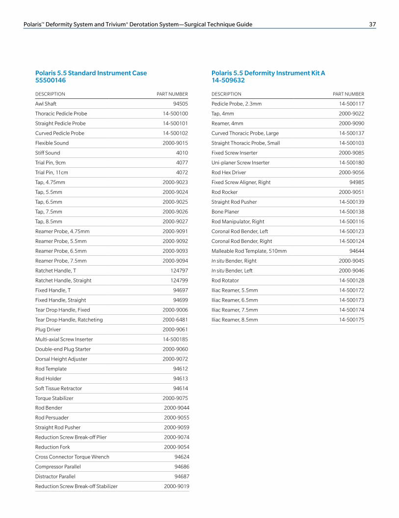
Polaris 5.5 Standard Instrument Case 55500146
Rod Bender 2000-9044
Rod Persuader 2000-9055
Straight Rod Pusher 2000-9059
Reduction Screw Break-off Plier 2000-9074
Reduction Fork 2000-9054
Cross Connector Torque Wrench 94624
Compressor Parallel 94686
Distractor Parallel 94687
Reduction Screw Break-off Stabilizer 2000-9019
Polaris 5.5 Deformity Instrument Kit A 14-509632

38 Polaris™ Deformity System and Trivium® Derotation System—Surgical Technique Guide
DESCRIPTION PART NUMBER
Deformity Compressor, Small 94659
Deformity Compressor, Large 94667
Deformity Distractor 94668
Cross Connector Caliper 14-500118
Fixed Cross Connector Bender, Left 94523
Fixed Cross Connector Bender, Right 94524
Pedicle Hook Starter 94510
Medium Laminar Hook Starter 94512
Narrow Laminar Hook Starter 94513
Thoracic Hook Starter 94515
Wide Laminar Hook Starter 94511
Vertical Hook Holder 2000-9086
Short Angle Hook Holder 2000-9088
Hook Impactor 2000-9089
DESCRIPTION PART NUMBER
Derotator Lever 14-500120
Horizontalizer, 55mm 14-500121
Horizontalizer, 75mm 14-500122
Cluster Linkage Rod, 25cm 14-501006
Cluster Linkage Rod, 38cm 14-501007
Comb, 30cm 14-501008
Comb, 36cm 14-501009
Handle Linkage Rod, Size 2–3 14-501003
Handle Linkage Rod, Size 3–4 14-501004
Handle Linkage Rod, Size 4–5 14-501005
Distractor Wedge 14-500125
T-handle Adaptor 14-500133
Wide Handle Derotator 14-500152
DESCRIPTION PART NUMBER
Multi-axial Screw, ø4mm × 20mm 50-6550MP
Multi-axial Screw, ø4mm × 25mm 50-6551MP
Multi-axial Screw, ø4mm × 30mm 50-6552MP
Multi-axial Screw, ø4mm × 35mm 50-6553MP
Multi-axial Screw, ø4mm × 40mm 50-6554MP
Multi-axial Screw, ø4.75mm × 20mm 50-6803MP
Multi-axial Screw, ø4.75mm × 25mm 50-6804MP
Multi-axial Screw, ø4.75mm × 30mm 50-6805MP
Multi-axial Screw, ø4.75mm × 35mm 50-6806MP
Multi-axial Screw, ø4.75mm × 40mm 50-6807MP
Multi-axial Screw, ø5.5mm × 30mm 50-6105MP
Multi-axial Screw, ø5.5mm × 35mm 50-6106MP
Multi-axial Screw, ø5.5mm × 40mm 50-6107MP
Multi-axial Screw, ø5.5mm × 45mm 50-6108MP
Multi-axial Screw, ø5.5mm × 50mm 50-6109MP
Multi-axial Screw, ø6.5mm × 30mm 50-6110MP
Multi-axial Screw, ø6.5mm × 35mm 50-6111MP
Multi-axial Screw, ø6.5mm × 40mm 50-6112MP
Multi-axial Screw, ø6.5mm × 45mm 50-6113MP
Multi-axial Screw, ø6.5mm × 50mm 50-6114MP
Multi-axial Screw, ø6.5mm × 55mm 50-6800MP
Multi-axial Screw, ø7.0mm × 30mm 50-6115MP
Multi-axial Screw, ø7.0mm × 35mm 50-6116MP
Multi-axial Screw, ø7.0mm × 40mm 50-6117MP
Multi-axial Screw, ø7.0mm × 45mm 50-6118MP
Multi-axial Screw, ø7.0mm × 50mm 50-6119MP
Multi-axial Screw, ø7.0mm × 55mm 50-6801MP
Multi-axial Reduction Screw, ø6.5mm × 40mm 53-6112MP
Multi-axial Reduction Screw, ø6.5mm × 45mm 53-6113MP
Multi-axial Reduction Screw, ø7.0mm × 45mm 53-6118MP
Multi-axial Reduction Screw, ø7.0mm × 50mm 53-6119MP
Helical Flange Plug 6451
Lateral Connector 6454
Lateral Connector, Extended 6455
Cross Connector, Small 6954
Cross Connector, Medium 6955
Cross Connector, Large 6956
Fixed Screw, ø4mm × 25mm 6310
Fixed Screw, ø4mm × 30mm 6311
Polaris 5.5 Deformity Instrument Kit B 14-509633
Polaris 5.5 Derotation Instrument Kit 14-509634
Polaris 6.35 Ti Standard Implants, LTPTL
KIT CONTENTS (continued)

Polaris™ Deformity System and Trivium® Derotation System—Surgical Technique Guide 39
Polaris 6.35 Ti Standard Implants LTPTL (continued)
DESCRIPTION PART NUMBER
Multi-axial Screw, ø7.5mm × 30mm 14-511530
Multi-axial Screw, ø7.5mm × 35mm 14-511535
Multi-axial Screw, ø7.5mm × 40mm 14-511540
Multi-axial Screw, ø7.5mm × 45mm 14-511545
Multi-axial Screw, ø7.5mm × 50mm 14-511550
Multi-axial Screw, ø7.5mm × 55mm 14-511555
Multi-axial Screw, ø8.5mm × 30mm 14-511630
Multi-axial Screw, ø8.5mm × 35mm 14-511635
Multi-axial Screw, ø8.5mm × 40mm 14-511640
Multi-axial Screw, ø8.5mm × 45mm 14-511645
Multi-axial Screw, ø8.5mm × 50mm 14-511650
Multi-axial Screw, ø8.5mm × 55mm 14-511655
Multi-axial Screw Inserter 14-501035
Polaris 6.35 Ti Large Diameter Screws 14-509640
DESCRIPTION PART NUMBER
Fixed Screw, ø4.0mm × 35mm 6312
Fixed Screw, ø4.0mm × 40mm 6313
Fixed Screw, ø4.75mm × 25mm 6385
Fixed Screw, ø4.75mm × 30mm 6386
Fixed Screw, ø4.75mm × 35mm 6387
Fixed Screw, ø4.75mm × 40mm 6388
Fixed Screw, ø5.5mm × 25mm 6719
Fixed Screw, ø5.5mm × 30mm 6720
Fixed Screw, ø5.5mm × 35mm 6721
Fixed Screw, ø5.5mm × 40mm 6722
Fixed Screw, ø5.5mm × 45mm 6723
Fixed Screw, ø6.5mm × 30mm 6730
Fixed Screw, ø6.5mm × 35mm 6731
Fixed Screw, ø6.5mm × 40mm 6732
Fixed Screw, ø6.5mm × 45mm 6733
Fixed Screw, ø6.5mm × 50mm 6734
Fixed Screw, ø7.0mm × 30mm 6749
Fixed Screw, ø7.0mm × 35mm 6750
Fixed Screw, ø7.0mm × 40mm 6751
Fixed Screw, ø7.0mm × 45mm 6752
Fixed Screw, ø7.0mm × 50mm 6753
CP Ti Rod, 6.35mm × 10cm 6008
CP Ti Rod, 6.35mm × 12cm 6009
CP Ti Rod, 6.35mm × 14cm 6010
CP Ti Rod with Hex, 6.35mm × 30cm 6015
CP Ti Rod with Hex, 6.35mm × 48cm 6016
Ti Alloy Rod, 6.35mm × 30cm 6035
Ti Alloy Rod, 6.35mm × 48cm 6036

40 Polaris™ Deformity System and Trivium® Derotation System—Surgical Technique Guide
DESCRIPTION PART NUMBER
Pedicle Hook, Small, 6mm 14-501150
Pedicle Hook, Medium, 7.5mm 14-501151
Pedicle Hook, Large, 9mm 14-501152
Left Angled Hook, Small, 6mm 14-501153
Right Angled Hook, Small, 6mm 14-501156
Left Angled Hook, Medium, 7.5mm 14-501154
Right Angled Hook, Medium, 7.5mm 14-501157
Left Angled Hook, Large, 9mm 14-501155
Right Angled Hook, Large, 9mm 14-501158
Narrow Laminar Hook, Small, 6mm 14-501162
Narrow Laminar Hook, Medium, 7.5mm 14-501163
Narrow Laminar Hook, Large, 9mm 14-501164
Narrow Reduced Laminar Hook, Small, 6mm
14-501165
Narrow Reduced Laminar Hook, Medium, 7.5mm
14-501166
Narrow Reduced Laminar Hook, Large, 9mm
14-501167
Wide Laminar Hook, Small, 6mm 14-501159
Wide Laminar Hook, Medium, 7.5mm 14-501160
Wide Laminar Hook, Large, 9mm 14-501161
Left Offset Hook, Small, 6mm 14-501168
Right Offset Hook, Small, 6mm 14-501171
Left Offset Hook, Medium, 7.5mm 14-501169
Right Offset Hook, Medium, 7.5mm 14-501172
Left Offset Hook, Large, 9mm 14-501170
Right Offset Hook, Large, 9mm 14-501173
Angled Blade Hook, Small, 6mm 14-501174
Angled Blade Hook, Medium, 7.5mm 14-501175
Angled Blade Hook, Large, 9mm 14-501176
Extended Hook, Small, 6mm 14-501177
Extended Hook, Medium, 7.5mm 14-501178
Extended Hook, Large, 9mm 14-501179
Fixed Cross Connector, 14mm 14-501041
Fixed Cross Connector, 16mm 14-501051
Fixed Cross Connector, 18mm 14-501052
Fixed Cross Connector, 20mm 14-501053
Fixed Cross Connector, 22mm 14-501054
Fixed Cross Connector, 24mm 14-501055
DESCRIPTION PART NUMBER
Multi-axial Screw, ø6.5mm × 60mm 14-501290
Multi-axial Screw, ø6.5mm × 70mm 14-501292
Multi-axial Screw, ø6.5mm × 80mm 14-501294
Multi-axial Screw, ø6.5mm × 90mm 14-501296
Multi-axial Screw, ø7.5mm × 60mm 14-501310
Multi-axial Screw, ø7.5mm × 70mm 14-501312
Multi-axial Screw, ø7.5mm × 80mm 14-501314
Multi-axial Screw, ø7.5mm × 90mm 14-501316
Multi-axial Screw, ø8.5mm × 60mm 14-501330
Multi-axial Screw, ø8.5mm × 70mm 14-501332
Multi-axial Screw, ø8.5mm × 80mm 14-501334
Multi-axial Screw, ø8.5mm × 90mm 14-501336
Lateral Connector, 24mm 6454
Lateral Connector, 34mm 6455
Lateral connector, 50mm 14-501220
Lateral Connector, 75mm 14-501221
Multi-axial Iliac Screw Inserter 14-501035
Polaris 6.35 Ti Hooks 14-509641
Polaris 6.35 Ti Iliac Fixation 14-509645
KIT CONTENTS (continued)

Polaris™ Deformity System and Trivium® Derotation System—Surgical Technique Guide 41
DESCRIPTION PART NUMBER
Standard Helical Flange SST Plug 14-575100
Derotation Helical Flange SST Plug 14-575110
Med SST Rod with Hex, 6.35mm × 510mm
14-575402
Hard SST Rod with Hex, 6.35mm × 510mm
14-575406
Extra Hard SST Rod with Hex, 6.35mm × 510mm
14-575410
Lateral Connector, 25mm 14-575120
Lateral Connector, 35mm 14-575122
Lateral Connector, 50mm 14-575124
Lateral Connector, 75mm 14-575126
Fixed Screw, ø4.75mm × 20mm 14-574220
Fixed Screw, ø4.75mm × 25mm 14-574225
Fixed Screw, ø4.75mm × 30mm 14-574230
Fixed Screw, ø4.75mm × 35mm 14-574235
Fixed Screw, ø4.75mm × 40mm 14-574240
Fixed Screw, ø4.75mm × 45mm 14-574245
Fixed Screw, ø5.5mm × 25mm 14-574325
Fixed Screw, ø5.5mm × 30mm 14-574330
Fixed Screw, ø5.5mm × 35mm 14-574335
Fixed Screw, ø5.5mm × 40mm 14-574340
Fixed Screw, ø5.5mm × 45mm 14-574345
Fixed Screw, ø5.5mm × 50mm 14-574350
Fixed Screw, ø5.5mm × 55mm 14-574355
Fixed Screw, ø6.5mm × 30mm 14-574430
Fixed Screw, ø6.5mm × 35mm 14-574435
Fixed Screw, ø6.5mm × 40mm 14-574440
Fixed Screw, ø6.5mm × 45mm 14-574445
Fixed Screw, ø6.5mm × 50mm 14-574450
Fixed Screw, ø6.5mm × 55mm 14-574455
Polaris 6.35 SST Deformity Implants 14-509670
DESCRIPTION PART NUMBER
Fixed Screw, ø7.5mm × 30mm 14-574530
Fixed Screw, ø7.5mm × 35mm 14-574535
Fixed Screw, ø7.5mm × 40mm 14-574540
Fixed Screw, ø7.5mm × 45mm 14-574545
Fixed Screw, ø7.5mm × 50mm 14-574550
Fixed Screw, ø7.5mm × 55mm 14-574555
Fixed Screw, ø8.5mm × 30mm 14-574630
Fixed Screw, ø8.5mm × 35mm 14-574635
Fixed Screw, ø8.5mm × 40mm 14-574640
Fixed Screw, ø8.5mm × 45mm 14-574645
Fixed Screw, ø8.5mm × 50mm 14-574650
Fixed Screw, ø8.5mm × 55mm 14-574655
Fixed Cross Connector, 12mm 14-575142
Fixed Cross Connector, 14mm 14-575143
Fixed Cross Connector, 16mm 14-575153
Fixed Cross Connector, 18mm 14-575154
Fixed Cross Connector, 20mm 14-575155
Fixed Cross Connector, 22mm 14-575156
Fixed Cross Connector, 24mm 14-575157

42 Polaris™ Deformity System and Trivium® Derotation System—Surgical Technique Guide
DESCRIPTION PART NUMBER
Pedicle Hook, Small, 6mm 14-575500
Pedicle Hook, Medium, 7.5mm 14-575502
Pedicle Hook, Large, 9mm 14-575504
Left Angled Hook, Small, 6mm 14-575506
Right Angled Hook, Small, 6mm 14-575508
Left Angled Hook, Medium, 7.5mm 14-575510
Right Angled Hook, Medium, 7.5mm 14-575512
Left Angled Hook, Large, 9mm 14-575514
Right Angled Hook, Large, 9mm 14-575516
Narrow Laminar Hook, Small, 6mm 14-575518
Narrow Laminar Hook, Medium, 7.5mm 14-575520
Narrow Laminar Hook, Large, 9mm 14-575522
Narrow Reduced Laminar Hook, Small, 6mm
14-575524
Narrow Reduced Laminar Hook, Medium, 7.5mm
14-575526
Narrow Reduced Laminar Hook, Large, 9mm
14-575528
Wide Laminar Hook, Small, 6mm 14-575530
Wide Laminar Hook, Medium, 7.5mm 14-575532
Wide Laminar Hook, Large, 9mm 14-575534
Left Offset Hook, Small, 6mm 14-575536
Right Offset Hook, Small, 6mm 14-575538
Left Offset Hook, Medium, 7.5mm 14-575540
Right Offset Hook, Medium, 7.5mm 14-575542
Left Offset Hook, Large, 9mm 14-575544
Right Offset Hook, Large, 9mm 14-575546
Angled Blade Hook, Small, 6mm 14-575548
Angled Blade Hook, Medium, 7.5mm 14-575550
Angled Blade Hook, Large, 9mm 14-575552
Extended Hook, Small, 6mm 14-575554
Extended Hook, Medium, 7.5mm 14-575556
Extended Hook, Large, 9mm 14-575558
DESCRIPTION PART NUMBER
Multi-axial Screw, ø4.75mm × 20mm 14-572220
Multi-axial Screw, ø4.75mm × 25mm 14-572225
Multi-axial Screw, ø4.75mm × 30mm 14-572230
Multi-axial Screw, ø4.75mm × 35mm 14-572235
Multi-axial Screw, ø4.75mm × 40mm 14-572240
Multi-axial Screw, ø4.75mm × 45mm 14-572245
Multi-axial Screw, ø4.75mm × 50mm 14-572250
Multi-axial Screw, ø5.5mm × 30mm 14-572330
Multi-axial Screw, ø5.5mm × 35mm 14-572335
Multi-axial Screw, ø5.5mm × 40mm 14-572340
Multi-axial Screw, ø5.5mm × 45mm 14-572345
Multi-axial Screw, ø5.5mm × 50mm 14-572350
Multi-axial Screw, ø5.5mm × 55mm 14-572355
Multi-axial Screw, ø6.5mm × 30mm 14-572430
Multi-axial Screw, ø6.5mm × 35mm 14-572435
Multi-axial Screw, ø6.5mm × 40mm 14-572440
Multi-axial Screw, ø6.5mm × 45mm 14-572445
Multi-axial Screw, ø6.5mm × 50mm 14-572450
Multi-axial Screw, ø6.5mm × 55mm 14-572455
Multi-axial Screw, ø7.5mm × 30mm 14-572530
Multi-axial Screw, ø7.5mm × 35mm 14-572535
Multi-axial Screw, ø7.5mm × 40mm 14-572540
Multi-axial Screw, ø7.5mm × 45mm 14-572545
Multi-axial Screw, ø7.5mm × 50mm 14-572550
Multi-axial Screw, ø7.5mm × 55mm 14-572555
Multi-axial Screw, ø8.5mm × 30mm 14-572630
Multi-axial Screw, ø8.5mm × 35mm 14-572635
Multi-axial Screw, ø8.5mm × 40mm 14-572640
Multi-axial Screw, ø8.5mm × 45mm 14-572645
Multi-axial Screw, ø8.5mm × 50mm 14-572650
Multi-axial Screw, ø8.5mm × 55mm 14-572655
Standard Helical Flange SST Plug 14-575100
Lateral Connector, 25mm 14-575120
Lateral Connector, 35mm 14-575122
Cross Connector, Extra Small 14-575168
Cross Connector, Small 14-575169
Cross Connector, Medium 14-575170
Cross Connector, Large 14-575171
Med SST Rod with Hex, 6.35mm × 510mm 14-575402
Polaris 6.35 SST Hooks 14-509671
Polaris 6.35 SST Standard Implants 14-509672
KIT CONTENTS (continued)

Polaris™ Deformity System and Trivium® Derotation System—Surgical Technique Guide 43
Polaris 6.35 SST Standard Implants 14-509672 (continued)
DESCRIPTION PART NUMBER
Multi-axial Screw, ø6.5mm × 70mm 14-573470
Multi-axial Screw, ø6.5mm × 80mm 14-573480
Multi-axial Screw, ø6.5mm × 90mm 14-573490
Multi-axial Screw, ø7.5mm × 60mm 14-573560
Multi-axial Screw, ø7.5mm × 70mm 14-573570
Multi-axial Screw, ø7.5mm × 80mm 14-573580
Multi-axial Screw, ø7.5mm × 90mm 14-573590
Multi-axial Screw, ø8.5mm × 60mm 14-573660
Multi-axial Screw, ø8.5mm × 70mm 14-573670
Multi-axial Screw, ø8.5mm × 80mm 14-573680
Multi-axial Screw, ø8.5mm × 90mm 14-573690
DESCRIPTION PART NUMBER
Multi-axial Reduction Screw, ø5.5mm × 30mm 14-577330
Multi-axial Reduction Screw, ø5.5mm × 35mm 14-577335
Multi-axial Reduction Screw, ø5.5mm × 40mm 14-577340
Multi-axial Reduction Screw, ø5.5mm × 45mm 14-577345
Multi-axial Reduction Screw, ø5.5mm × 50mm 14-577350
Multi-axial Reduction Screw, ø5.5mm × 55mm 14-577355
Multi-axial Reduction Screw, ø6.5mm × 30mm 14-577430
Multi-axial Reduction Screw, ø6.5mm × 35mm 14-577435
Multi-axial Reduction Screw, ø6.5mm × 40mm 14-577440
Multi-axial Reduction Screw, ø6.5mm × 45mm 14-577445
Multi-axial Reduction Screw, ø6.5mm × 50mm 14-577450
Multi-axial Reduction Screw, ø6.5mm × 55mm 14-577455
Multi-axial Reduction Screw, ø7.5mm × 30mm 14-577530
Multi-axial Reduction Screw, ø7.5mm × 35mm 14-577535
Multi-axial Reduction Screw, ø7.5mm × 40mm 14-577540
Multi-axial Reduction Screw, ø7.5mm × 45mm 14-577545
Multi-axial Reduction Screw, ø7.5mm × 50mm 14-577550
Multi-axial Reduction Screw, ø7.5mm × 55mm 14-577555
Polaris 6.35 SST Iliac Fixation 14-509674
Polaris 6.35 SST Reduction Screw 14-509675
DESCRIPTION PART NUMBER
Multi-axial SST Screw, ø4mm × 20mm 14-572120
Multi-axial SST Screw, ø4mm × 25mm 14-572125
Multi-axial SST Screw, ø4mm × 30mm 14-572130
Multi-axial SST Screw, ø4mm × 35mm 14-572135
Multi-axial SST Screw, ø4mm × 40mm 14-572140
Fixed SST Screw, ø4mm × 20mm 14-574120
Fixed SST Screw, ø4mm × 25mm 14-574125
Fixed SST Screw, ø4mm × 30mm 14-574130
Fixed SST Screw, ø4mm × 35mm 14-574135
Fixed SST Screw, ø4mm × 40mm 14-574140
Polaris 6.35 SST ø4.0mm Screw Case 14-509676
DESCRIPTION PART NUMBER
Hard SST Rod with Hex, 6.35mm × 510mm 14-575406
Extra Hard SST Rod with Hex, 6.35mm × 510mm
14-575410
Multi-axial Screw Inserters 14-501035

44 Polaris™ Deformity System and Trivium® Derotation System—Surgical Technique Guide
DESCRIPTION PART NUMBER
Awl 4005
Ball Tip Probe 4010
Trial Pin, 11cm 4072
Trial Pin, 9cm 4077
Ratcheting Straight Handle 4329
Tap, 4mm 4363M
Tap, 4.75mm 4364M
Tap, 5.5mm 4365M
Tap, 6.5mm 4366M
Tap, 7mm 4367M
Ratcheting T-Handle 4373
3.2 Straight Probe 4385
3.2 Curved Probe 4396
Lever Activated Multi-axial Screw Driver 4398M
Multi-axial Screw Bi-directional Driver 4500M
Fixed Screw Bi-directional Driver 4516M
Rod Holder 4046
Wing Rocker 4088
Multi-axial Screw Height Adjustor 4493
Rod Bender 4029
In situ Bender, Left 4030
In situ Bender, Right 4031
Bifid Retractor 4032
Plug Starter, 4.8mm 4216M
Screw Fork 4374M
Rod Rotator 4377
Reduction Seat Thread Gripper 4055
Torque Stabilizer 4484
Reduction Seat Depth Gauge 4485
Compressor 4496
Distractor 4497
Rod Persuader 4498
Cross Connector Wrench 4513
Torque Measuring Wrench 4490M
DESCRIPTION PART NUMBER
Double-end Plug Starter 14-501010
Fixed Screw Inserter 14-501199
Fixed Screw Height Adjustor 14-501022
Bone Planer 14-501029
Malleable Trial Rod 4083
Lateral In situ Bender, Left 4160
Lateral In situ Bender, Right 4161
Rod Manipulator, Right 14-501023
Straight Rod Pusher 4066
Hex End Wrench 4003
Rod Rotator 4052
Plug Driver 4370
Torque-limiting with Shaft 4378M
Polaris 6.35 General Instruments LTPI
Polaris 6.35 Deformity Instrument Kit A 14-509642
DESCRIPTION PART NUMBER
Cross Connector Caliper 14-501190
Fixed Cross Connector Bender, Left 14-501091
Fixed Cross Connector Bender, Right 14-501092
Pedicle Hook Starter 94510
Medium Laminar Hook Starter 94512
Narrow Laminar Hook Starter 94513
Thoracic Hook Starter 94515
Wide Laminar Hook Starter 94511
Vertical Hook Holder 14-501036
Short Angle Hook Holder 14-501037
Hook Impactor 14-501038
Polaris 6.35 Deformity Instrument Kit B 14-509643
KIT CONTENTS (continued)

Polaris™ Deformity System and Trivium® Derotation System—Surgical Technique Guide 45
DESCRIPTION PART NUMBER
Derotator Lever 14-501000
Horizontalizer, 55mm 14-501001
Horizontalizer, 75mm 14-501002
Cluster Linkage Rod, 25cm 14-501006
Cluster Linkage Rod, 38cm 14-501007
Comb, 30cm 14-501008
Comb, 36cm 14-501009
2–3 Handle Linkage Rod 14-501003
3–4 Handle Linkage Rod 14-501004
4–5 Handle Linkage Rod 14-501005
Ball Tipped Hex Plug Driver 14-501011
Distractor Wedge 14-500125
Ti Derotation Helical Flange Plug 6710
Wide Handle Derotator 14-501187
Polaris 6.35 Derotation System Case 14-509644

46 Polaris™ Deformity System and Trivium® Derotation System—Surgical Technique Guide
INSTRUMENTS AND IMPLANTS: 5.5mm DEFORMITY IMPLANTS
MULTI-AXIAL SCREW FAMILY
Ranging in lengths from 20mm–55mm (in 5mm increments) Note: All implants are available in stainless steel and are marked with “SST.” Stainless steel cannot be color-coded.
FIXED SCREW FAMILY
Ranging in lengths from 20mm–55mm (in 5mm increments)
Note: Polaris 5.5™ Titanium Spinal System 4.0mm diameter screws are not for use with cobalt chrome alloy rods.
DIAMETER COLOR CODING
4mm Gray
4.75mm Green
5.5mm Gold
6.5mm Blue
7.5mm Purple
8.5mm Bronze
DIAMETER COLOR CODING
4mm Gray
4.75mm Green
5.5mm Gold
6.5mm Blue
7.5mm Purple
8.5mm Bronze
REDUCTION MULTI-AXIAL SCREWS
Ranging in lengths from 30mm–55mm (in 5mm increments)
DIAMETER COLOR CODING
5.5mm Gold
6.5mm Blue
7.5mm Purple
8.5mm Bronze
MULTI-AXIAL ILIAC SCREWS
Ranging in lengths from 60mm–90mm in 10mm increments; double-lead screw shaft thread design
DIAMETER COLOR CODING
6.5mm Blue
7.5mm Purple
8.5mm Bronze

Polaris™ Deformity System and Trivium® Derotation System—Surgical Technique Guide 47
TRIVIUM DEROTATION HELICAL FLANGE PLUG
The interface between the seat and the plug incorporates Helical Flange technology:
• Derotation Helical Flange plugs
• Two tings on the bottom:
• Prevents rod rotation after torquing*
STANDARD HELICAL FLANGE PLUG
The interface between the seat and the plug incorporates Helical Flange technology.
Helical Flange technology allows the flanges on the plug and the seat to lock together to minimize head splay and cross-threading.
Ti Alloy
CP Ti
RODS
Various rod options are available:
• Commercially pure titanium (CP Ti), 510mm
• Titanium alloy (Ti Alloy), 510mm
• Stainless steel (SST), 510mm
• Medium strength
• Hard strength
• Extra-hard strength
• Cobalt chrome alloy (CoCrMo), 300mm and 510mm
• Extra-hard tensile strength
CoCrMo
Stainless Steel
*Data on file.
48 Polaris™ Deformity System and Trivium® Derotation System—Surgical Technique Guide
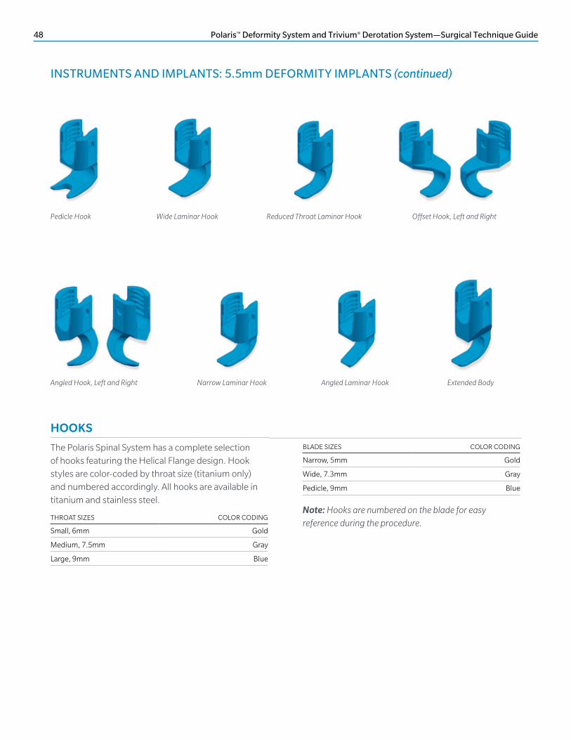
HOOKS
The Polaris Spinal System has a complete selection of hooks featuring the Helical Flange design. Hook styles are color-coded by throat size (titanium only) and numbered accordingly. All hooks are available in titanium and stainless steel.
THROAT SIZES COLOR CODING
Small, 6mm Gold
Medium, 7.5mm Gray
Large, 9mm Blue
BLADE SIZES COLOR CODING
Narrow, 5mm Gold
Wide, 7.3mm Gray
Pedicle, 9mm Blue
Note: Hooks are numbered on the blade for easy reference during the procedure.
Pedicle Hook Wide Laminar Hook Reduced Throat Laminar Hook
Angled Laminar Hook Extended Body
Offset Hook, Left and Right
Narrow Laminar HookAngled Hook, Left and Right
INSTRUMENTS AND IMPLANTS: 5.5mm DEFORMITY IMPLANTS (continued)

Polaris™ Deformity System and Trivium® Derotation System—Surgical Technique Guide 49
25mm
12mm 14mm 16mm
18mm 20mm
24mm
35mm
50mm
75mm
22mm
LATERAL CONNECTORS
Open lateral connectors are offered in four sizes (size is measured from the center of the seat to the end of the post of the lateral connector). The open design uses the standard Helical Flange plugs and provides strong, secure fixation.
FIXED CROSS CONNECTORS
Ranging in size from 12mm–24mm.
Extra-extra Small Cross Connector
Extra Small Cross Connector
Small Cross Connector
Medium Cross Connector
Large Cross Connector
TELESCOPING CROSS CONNECTORS
Ranging in size from 16mm–75mm.
50 Polaris™ Deformity System and Trivium® Derotation System—Surgical Technique Guide
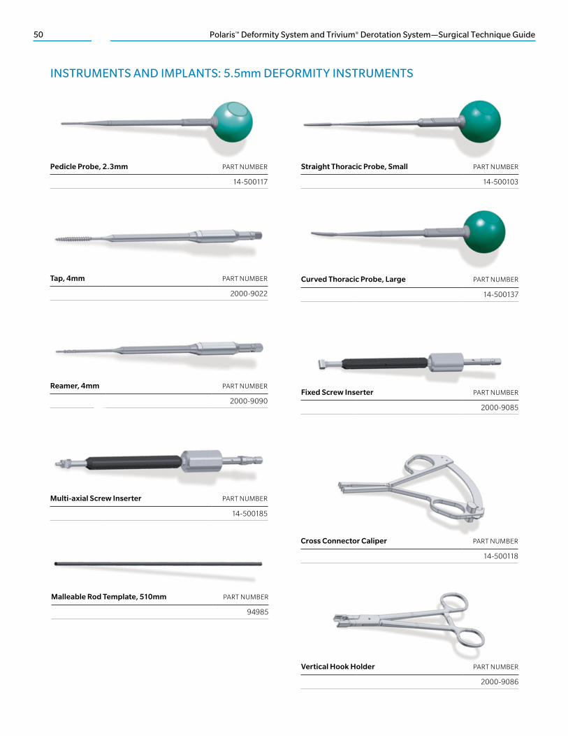
Pedicle Probe, 2.3mm PART NUMBER
14-500117
Straight Thoracic Probe, Small PART NUMBER
14-500103
Tap, 4mm PART NUMBER
2000-9022
Curved Thoracic Probe, Large PART NUMBER
14-500137
Reamer, 4mm PART NUMBER
2000-9090Fixed Screw Inserter PART NUMBER
2000-9085
INSTRUMENTS AND IMPLANTS: 5.5mm DEFORMITY INSTRUMENTS
Multi-axial Screw Inserter PART NUMBER
14-500185
Cross Connector Caliper PART NUMBER
14-500118
Malleable Rod Template, 510mm PART NUMBER
94985
Vertical Hook Holder PART NUMBER
2000-9086

Polaris™ Deformity System and Trivium® Derotation System—Surgical Technique Guide 51
Rod Rotator PART NUMBER
14-500128
Short Angle Hook Holder PART NUMBER
2000-9088
Pedicle Hook Starter PART NUMBER
94510
Wide Laminar Hook Starter PART NUMBER
94511
Narrow Laminar Hook Starter PART NUMBER
94513
Thoracic Hook Starter PART NUMBER
94515
Medium Laminar Hook Starter PART NUMBER
94512
Hook Impactor PART NUMBER
2000-9089
Deformity Compressor, Large PART NUMBER
94667
In situ Benders PART NUMBER
Left 2000-9046
Right 2000-9045

52 Polaris™ Deformity System and Trivium® Derotation System—Surgical Technique Guide
Deformity Distractor PART NUMBER
94668
Fixed Cross Connector Benders PART NUMBER
Left 94523
Right 94524
Deformity Compressor, Small PART NUMBER
94659
Wide Handle Derotator PART NUMBER
14-500152
Derotator Lever PART NUMBER
14-500120
Comb PART NUMBER
Small, 30cm 14-501008
Large, 36cm 14-501009
Cluster Linkage Rod PART NUMBER
Small, 25cm 14-501006
Large, 38cm 14-501007
Horizontalizer PART NUMBER
Small, 55mm 14-500121
Large, 75mm 14-500122
INSTRUMENTS AND IMPLANTS: 5.5mm DEFORMITY INSTRUMENTS (continued)

Polaris™ Deformity System and Trivium® Derotation System—Surgical Technique Guide 53
Handle Linkage Rod PART NUMBER
Size 2–3 14-501003
Size 3–4 14-501004
Size 4–5 14-501005
Bone Planer PART NUMBER
14-500138
Rod Rocker PART NUMBER
2000-9051
Rod Manipulator, Right PART NUMBER
14-500116
T-handle Adaptor PART NUMBER
14-500133
Straight Rod Pusher PART NUMBER
14-500139
Rod Hex Driver PART NUMBER
2000-9056
Distractor Wedge PART NUMBER
14-500125
Fixed Screw Aligner, Right PART NUMBER
94985
Iliac Reamer, 5.5mm PART NUMBER
14-500172

54 Polaris™ Deformity System and Trivium® Derotation System—Surgical Technique Guide
Iliac Reamer, 6.5mm PART NUMBER
14-500173
Iliac Reamer, 7.5mm PART NUMBER
14-500174
Iliac Reamer, 8.5mm PART NUMBER
14-500175
INSTRUMENTS AND IMPLANTS: 5.5mm DEFORMITY INSTRUMENTS (continued)

Polaris™ Deformity System and Trivium® Derotation System—Surgical Technique Guide 55
ø7.5mm ø8.5mm
MULTI-AXIAL SCREW FAMILY
Ranging in lengths: 5mm increments Note: All implants are available in stainless steel and are
marked with “SST.” Stainless steel cannot be color-coded.
LARGE DIAMETER
Ranging in lengths (30mm–55mm): 5mm increments
Note: Polaris 6.35 System large diameter screws must use the multi-axial screw inserter, which incorporates a male pentalobe tip to interface with the female pentalobe proximal screw shaft.
SIZES
ø4.75mm (20mm–40mm)
ø5.5mm (30mm–40mm)
ø6.5mm (30mm–55mm)
ø7mm (30mm–55mm)
INSTRUMENTS AND IMPLANTS: 6.35mm DEFORMITY IMPLANTS
REDUCTION MULTI-AXIAL SCREW
Standard offering is 6.5mm diameter, 40mm and 45mm length: 7mm diameter, 45mm and 50mm length
FIXED SCREW FAMILY
Ranging in lengths: 5mm increments
SIZES
ø4mm (25mm–40mm)
ø4.75mm (25mm–40mm)
ø5.5mm (25mm–45mm)
ø6.5mm (30mm–50mm)
ø7mm (30mm–50mm)

56 Polaris™ Deformity System and Trivium® Derotation System—Surgical Technique Guide
HELICAL FLANGE TRIVIUM DEROTATION PLUG
The interface between the seat and the plug incorporates Helical Flange technology:
• Derotation Helical Flange plugs
• Two tings on the bottom:
• Prevents rod rotation after torquing*
HELICAL FLANGE STANDARD PLUG
The interface between the seat and the plug incorporates Helical Flange technology.
Helical Flange technology allows the flanges on the plug and the seat to lock together to minimize head splay and cross-threading.
INSTRUMENTS AND IMPLANTS: 6.35mm DEFORMITY IMPLANTS (continued)

Polaris™ Deformity System and Trivium® Derotation System—Surgical Technique Guide 57
HOOKS
The Polaris Spinal System has a complete selection of hooks featuring the Helical Flange design. Hook styles are color-coded by throat size (titanium only) and numbered accordingly.
THROAT SIZES COLOR CODING
Small, 6mm Gold
Medium, 7.5mm Gray
Large, 9mm Blue
BLADE SIZES COLOR CODING
Narrow, 5mm Gold
Wide, 7.3mm Gray
Pedicle, 9mm Blue
Note: Hooks are numbered on the blade for easy reference during the procedure.
Pedicle Hook Wide Laminar Hook Reduced Throat Laminar Hook
Angled Laminar Hook Extended Body
Offset Hook, Left and Right
Narrow Laminar HookAngled Hook, Left and Right
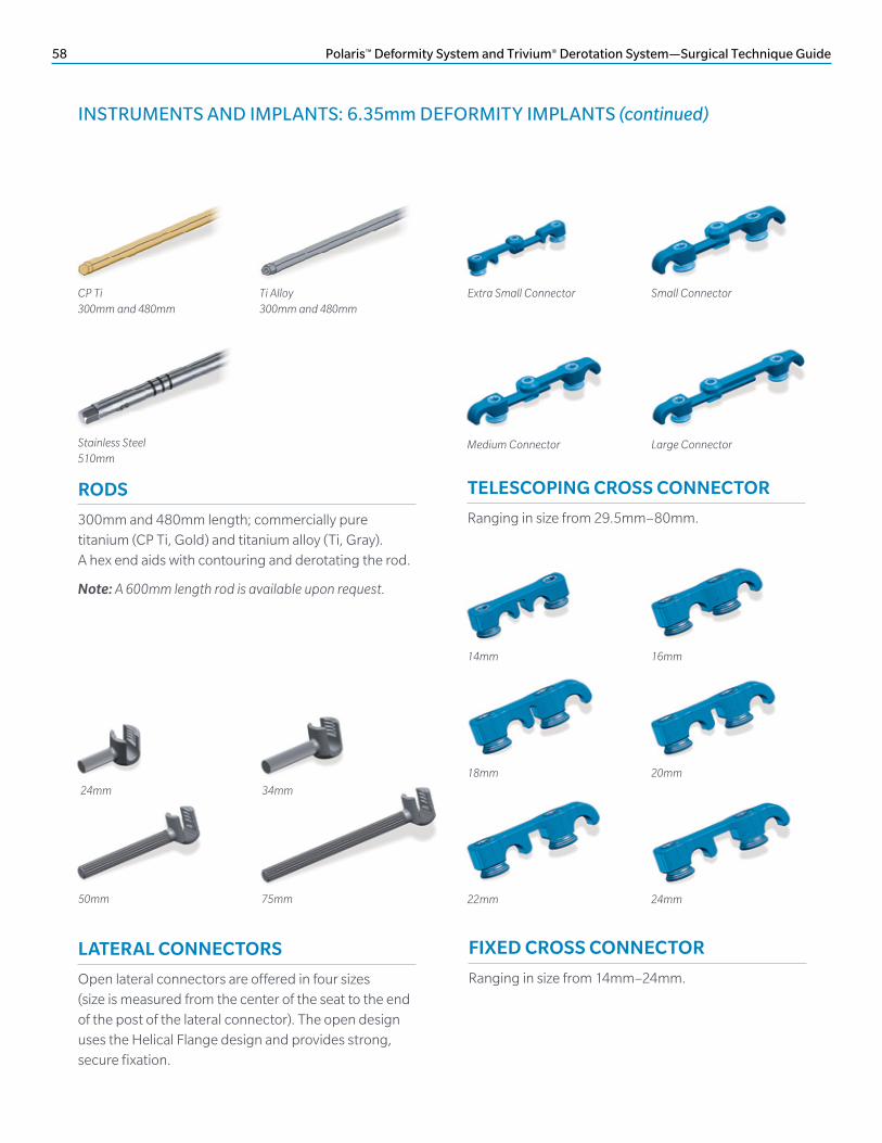
58 Polaris™ Deformity System and Trivium® Derotation System—Surgical Technique Guide
CP Ti300mm and 480mm
Ti Alloy300mm and 480mm
24mm 34mm
50mm 75mm
Stainless Steel510mm
RODS
300mm and 480mm length; commercially pure titanium (CP Ti, Gold) and titanium alloy (Ti, Gray). A hex end aids with contouring and derotating the rod.
Note: A 600mm length rod is available upon request.
LATERAL CONNECTORS
Open lateral connectors are offered in four sizes (size is measured from the center of the seat to the end of the post of the lateral connector). The open design uses the Helical Flange design and provides strong, secure fixation.
Medium Connector Large Connector
Extra Small Connector Small Connector
22mm 24mm
14mm 16mm
20mm18mm
TELESCOPING CROSS CONNECTOR
Ranging in size from 29.5mm–80mm.
FIXED CROSS CONNECTOR
Ranging in size from 14mm–24mm.
INSTRUMENTS AND IMPLANTS: 6.35mm DEFORMITY IMPLANTS (continued)

Polaris™ Deformity System and Trivium® Derotation System—Surgical Technique Guide 59
Plug Driver PART NUMBER
4370
Double-end Plug Starter PART NUMBER
14-501010
Ball Tipped Hex Plug Driver PART NUMBER
14-501011
Fixed Screw Height Adjuster PART NUMBER
14-501022
Torque-limiting with Shaft PART NUMBER
4378M
Fixed Screw Inserter PART NUMBER
14-501199
INSTRUMENTS AND IMPLANTS: 6.35mm DEFORMITY INSTRUMENTS (continued)
Short Angle Hook Holder PART NUMBER
14-501037
Cross Connector Caliper PART NUMBER
14-501190
Pedicle Hook Starter PART NUMBER
94510

60 Polaris™ Deformity System and Trivium® Derotation System—Surgical Technique Guide
Vertical Hook Holder PART NUMBER
14-501036
Narrow Laminar Hook Starter PART NUMBER
94513
Medium Laminar Hook Starter PART NUMBER
94512Bone Planer PART NUMBER
14-501029
Wide Laminar Hook Starter PART NUMBER
94511Multi-axial Screw Inserter PART NUMBER
14-501035
Thoracic Hook Starter PART NUMBER
94515Malleable Trial Rod PART NUMBER
4083
Hook Impactor PART NUMBER
14-501038
In situ Benders PART NUMBER
Left 4030
Right 4031
INSTRUMENTS AND IMPLANTS: 6.35mm DEFORMITY INSTRUMENTS (continued)

Polaris™ Deformity System and Trivium® Derotation System—Surgical Technique Guide 61
Fixed Cross Connector Benders PART NUMBER
Left 14-501091
Right 14-501092
Lateral In Situ Benders PART NUMBER
Left 4160
Right 4161
Wide Handle Derotator PART NUMBER
14-501187
Cluster Linkage Rod PART NUMBER
Small, 25cm 14-501006
Large, 38cm 14-501007
Horizontalizer PART NUMBER
Small, 55mm 14-501001
Large, 75mm 14-501002
Derotator Lever PART NUMBER
14-501000
Handle Linkage Rod PART NUMBER
2–3 14-501003
3–4 14-501004
4–5 14-501005
Comb PART NUMBER
Small, 30cm 14-501008
Large, 36cm 14-501009

62 Polaris™ Deformity System and Trivium® Derotation System—Surgical Technique Guide
Straight Rod Pusher PART NUMBER
4066
Rod Manipulator, Right PART NUMBER
14-501023
Hex End Wrench PART NUMBER
4003
Distractor Wedge PART NUMBER
14-500125
INSTRUMENTS AND IMPLANTS: 6.35mm DEFORMITY INSTRUMENTS (continued)

Polaris™ Deformity System and Trivium® Derotation System—Surgical Technique Guide 63
Description
The Polaris Spinal System is a spinal fixation device made from titanium alloy (Ti-6Al-4V), unalloyed titanium and cobalt chrome alloy (Co-28Cr-Mo) 5.5mm diameter rods. The system includes screws, various types and sizes of rods, locking nuts, hooks, lateral connectors, plugs, fixation washers, dominoes and various cross connectors. Various instruments are also available as part of the Polaris Spinal System for use by the surgeon to facilitate implantation of the device.
Indications for Use
The Polaris Spinal System is a non-cervical spinal fixation device intended for immobilization and stabilization as an adjunct to fusion as a pedicle screw fixation system, a posterior hook and sacral/iliac screw fixation system or as an anterolateral fixation system. Pedicle screw fixation is limited to skeletally mature patients and for use with autograft. The device is indicated for all the following indications: degenerative disc disease (defined as discogenic back pain with degeneration of the disc confirmed by history and radiographic studies), spondylolisthesis, trauma, (i.e., fracture or dislocation), deformity or curvature (i.e., scoliosis, kyphosis and lordosis), tumor, stenosis, pseudarthrosis and failed previous fusion.
The Ballista® instruments are intended to be used with the Polaris 5.5 implants. The Ballista instruments, when used with the Ballista cannulated screws and percutaneous rods, are indicated to provide the surgeon with a percutaneous approach for posterior spinal surgery for the following indications: degenerative disc disease (defined as discogenic back pain with degeneration of the disc confirmed by history and radiographic studies), spondylolisthesis, trauma, (i.e., fracture or dislocation), deformity or curvature (i.e., scoliosis, kyphosis, and lordosis), tumor, stenosis, pseudarthrosis and failed previous fusion that warrant the use of a non-cervical spinal fixation device intended for use as a pedicle screw fixation system or sacral/iliac screw fixation system. Pedicle screw fixation is limited to skeletally mature patients and for use with autograft.
The AccuVision® Instruments, when used with the Polaris Spinal System, are indicated to provide the surgeon with a minimally invasive approach for posterior spinal surgery for the following indications: degenerative disc disease (defined as discogenic back pain with degeneration of the disc confirmed by history and radiographic studies), spondylolisthesis, trauma, (i.e., fracture or dislocation), deformity or curvature (i.e., scoliosis, kyphosis and lordosis), tumor, stenosis, pseudarthrosis and failed previous fusion that warrant a noncervical spinal fixation device intended for use as a pedicle screw fixation system or sacral/iliac screw fixation system.
Pedicle screw fixation is limited to skeletally mature patients and for use with autograft. The AccuVision Illuminated Blade Tip is intended for the illumination of surgical procedures and exclusively for use with the AccuVision retractor frame.
The AccuVision Illuminated Blade Tip is a sterile, single-use, latex free, plastic fiber-optic device intended to bring cool-area lighting into spinal surgeries. The AccuVision Illuminated Blade Tip is intended for use with a 300 watt xenon illuminator, using a 3mm fiber optic cable with a female ACMI connector.
Contraindications
• Spinal infection or inflammation
• Morbid obesity
• Mental illness, alcoholism or drug abuse
• Pregnancy
• Metal sensitivity/foreign body sensitivity
• Patients with inadequate tissue coverage over the operative site
• Open wounds local to the operative area
• Any case not described in the specific indications
The AccuVision Blade Tips present no additional contraindications. The user should be familiar with the use of light sources and cables and should take precautions accordingly.
Warnings
• The safety and effectiveness of pedicle screw spinal systems have been established only for spinal conditions with significant mechanical instability or deformity requiring fusion with instrumentation. These conditions are significant mechanical instability or deformity of the thoracic, lumbar and sacral spine secondary to severe spondylolisthesis (grades 3 and 4) of the L5–S1 vertebra, degenerative spondylolisthesis with objective evidence of neurologic impairment, fracture, dislocation, scoliosis, kyphosis, spinal tumor and failed previous fusion (pseudarthrosis). The safety and effectiveness of these devices for any other conditions are unknown. Potential risks identified with the use of this device, which may require additional surgery, include device component fracture, loss of fixation, nonunion, fracture of the vertebra, neurological injury and vascular or visceral injury.
• Implant Strength and Loading. The Polaris Spinal System is intended to assist healing and is not intended to replace normal bony structures. Loads produced by weight
IMPORTANT INFORMATION ON POLARIS DEFORMITY SYSTEM AND TRIVIUM DEROTATION SYSTEM

64 Polaris™ Deformity System and Trivium® Derotation System—Surgical Technique Guide
bearing and activity levels will dictate the longevity of the implant. These devices are not designed to withstand the unsupported stress of full weight bearing or load bearing, and cannot withstand activity levels and/or loads equal to those placed on normal healthy bone. If healing is delayed or does not occur, the implant could eventually break due to metal fatigue.
• Therefore, it is important that immobilization of the operative site be maintained until firm bony union (confirmed by clinical and radiographic examination) is established. The surgeon must be thoroughly knowledgeable in the medical, surgical, mechanical and metallurgical aspects of the Polaris Spinal System. Postoperative care is extremely important. The patient should be warned that noncompliance with postoperative instructions could lead to breakage of the implant and/or possible migration requiring revision surgery to remove the implant.
• Selection of Implants. Selection of the proper size, shape and design of the implant increases the potential for success. While proper selection can help minimize risks, the size and shape of human bones present limitations on the size and strength of implants.
• Corrosion. Contact of dissimilar metals accelerates the corrosion process, which could increase the possibility of fatigue fracture of the implants. Therefore, only use like or compatible metals for implants that are in contact with each other. Never use stainless steel and titanium implant components in the same construct. Cobalt chrome alloy rods should not be used with stainless steel components. Cobalt chrome alloy rods are to be used ONLY with titanium implant components in the same construct.
• Sterile Packaging. The AccuVision plastic components are packaged sterile as a single use device. Do not resterilize for reuse.
• Light Source. The AccuVision Illuminated Blade Tip is designed for use with 300 watt xenon illuminators, using a 3mm fiber optic cable. Do not use light sources rated higher than 300 watts, or cables with fiber optic bundles of more than 3mm diameter. Use of higher watt sources or larger diameter cables could result in overheating, causing product failure and patient injury. Should the blade assembly become cut, collect fluid inside, appear broken or damaged in any manner, it should be replaced to minimize risk to the patient.
• Do not operate the light source and cable without the light strip attached. Without the AccuVision Illuminated Blade Tip, the output from the fiberoptic cable is extremely bright, hot and may cause burns, ignite drapes/gowns or temporarily blind vision.
Limits of System Compatibility
• When used with the Ballista instruments, the use of the Ballista cannulated 5.5 screws and percutaneous 5.5 rods is limited to the implantation of rod lengths of 100mm or less, and excludes the use of system cross connectors or hooks. When used with the AccuVision instruments, is limited to the implantation of rod lengths of 100mm or less, and excludes the use of system cross connectors or hooks.
Precautions
• Single Use Only. Never re-implant an explanted device under any circumstances. Although the device appears undamaged, it may have small defects and internal stress patterns, which may lead to early breakage.
• Handling of Implants. If contouring of the rod is required, avoid sharp bends and reverse bends. Avoid notching or scratching of the device, which could increase internal stresses and lead to early breakage.
• Implant Removal After Healing. After healing is complete, the implant is intended to be removed since it is no longer necessary. Implants that are not removed may result in complications such as implant loosening, fracture, corrosion, migration, pain or stress shielding of bone, particularly in young, active patients. Implant removal should be followed by adequate postoperative management.
• Adequate Patient Instructions. A patient must be instructed on the limitations of the metallic implant, and should be cautioned regarding physical activity and weight bearing or load bearing prior to complete healing.
• Surgical Techniques. The implantation of pedicle screw spinal systems should be performed only by experienced spinal surgeons with specific training in the use of this pedicle screw spinal system because this is a technically demanding procedure presenting a risk of serious injury to the patient. Please refer to the specific surgical technique for this device for more information.
• Illuminated Blades. Light sources vary widely in emission of visible and infrared energy. As a precautionary measure, when using AccuVision Illuminated Blade Tips, we recommend occasionally monitoring connector temperature during first time use with a new light source or lamp; thereafter if needed. As is common with fiber-optic equipment, the metal portion of the connector can become hot to the touch. Use plastic grip as a handle. Do not place the metal ring portion of connector directly on the patient’s skin. After use, the AccuVision Blade Tips may be a potential biohazard. Handle and dispose of in accordance with accepted medical practice and applicable local, state and federal laws and regulations.
IMPORTANT INFORMATION ON POLARIS DEFORMITY SYSTEM AND TRIVIUM DEROTATION SYSTEM (continued)

Polaris™ Deformity System and Trivium® Derotation System—Surgical Technique Guide 65
Possible Adverse Effects
• Nonunion (pseudarthrosis) or delayed union.
• Bending, fracture, loosening or migration of the implant.
• Metal sensitivity or foreign body reaction.
• Decrease in bone density due to stress shielding.
• Pain, discomfort or abnormal sensations due to presence of the implant.
• Nerve, soft tissue or blood vessel damage due to surgical trauma.
• Fracture of bony structures.
• Nerve root or spinal cord impingement.
• Dural leak.
• Bursitis.
• Necrosis of bone.
• Hemorrhage.
• Infection.
• Death.
Directions for Use—Illuminated Blades
• See the AccuVision surgical technique for instructions on attaching the AccuVision Illuminated Blade Tip to the retractor system. The AccuVision Illuminated Blade Tip should be used in accordance with all instructions for the AccuVision retractor frame. The AccuVision Illuminated Blade Tip connects to a light source used for head lamps or endoscopes. A 3mm fiber-optic cable with an ACMI fitting attaches the light source and AccuVision Illuminated Blade Tip. Make sure the Lighted Blade connector is securely attached to the cable. The cable should be in good repair with clean optics. Dirty optics or cables in need of repair can cause excessive heat at the connectors. Turning down overhead lighting may improve visualization within the surgical site. Sterile unless package is opened or damaged. Do not use if package is opened or damaged.
Sterilization
• The Polaris Spinal System is provided nonsterile, and must be sterilized prior to use. All packaging materials must be removed prior to sterilization. The following steam sterilization parameters are recommended.
Note: Allow for cooling.
• Individuals not using the recommended method, temperature and time are advised to validate any alternative methods or cycles using an approved method or standard. The AccuVision sterile packaged plastic components are sterilized by exposure to a minimum dose of 25-kGy gamma radiation or by EtO, according to individual component labeling. These components are for single use only and cannot be re-sterilized. Do not use if package has been compromised.
Care and Handling Instructions
• Sterile packaged, single-use components should be inspected prior to use for and damage or contamination.
• If components appear damaged, do not use.
Caution
• Federal law (USA) restricts this device to sale by or on the order of a physician.
Cycle Temperature Time
High Vacuum 132° C (270° F) 8 minutes

66 Polaris™ Deformity System and Trivium® Derotation System—Surgical Technique Guide
NOTES


800.447.3625 ⁄ zimmerbiomet.com©2016 Zimmer Biomet Spine, Inc. All rights reserved.
All content herein is protected by copyright, trademarks and other intellectual property rights, as applicable, owned by or licensed to Zimmer Biomet Spine, Inc. or its affiliates unless otherwise indicated, and must not be redistributed, duplicated or disclosed, in whole or in part, without the express written consent of Zimmer Biomet Spine. This material is intended for health care professionals. Distribution to any other recipient is prohibited.
Crossbar is a trademark of SeaSpine, Inc. Helical Flange is a registered trademark of Roger P. Jackson.
0258.1-GLBL-en-REV1216
Disclaimer: This document is intended exclusively for physicians and is not intended for laypersons. Information on the products and procedures contained in this document is of a general nature and does not represent and does not constitute medical advice or recommendations. Because this information does not purport to constitute any diagnostic or therapeutic statement with regard to any individual medical case, each patient must be examined and advised individually, and this document does not replace the need for such examination and/or advice in whole or in part.
Caution: Federal (USA) law restricts this device to sale by or on the order of a physician. Rx Only. Please see the product Instructions for Use for a complete listing of the indications, contraindications, precautions, warnings and adverse effects.
Manufactured by: Zimmer Biomet Spine, Inc. 10225 Westmoor Dr. Westminster, CO 80021 USA
Zimmer GmbHSulzerallee 8CH-8404 WinterthurSwitzerland+41 058.854.80.00


![A mathematical trivium II - Brown High Energy Physics · A mathematical trivium II ... A. Einstein My appeal in "A mathematical trivium" [1] ... The final version given here is unlikely](https://img.pdfslide.us/doc/110x75/5ac16e3e7f8b9ad73f8ce820/a-mathematical-trivium-ii-brown-high-energy-mathematical-trivium-ii-a-einstein.jpg)