Embed Size (px)
Citation preview
Pointshop 3D: An Interactive System for Point-Based Surface Editing
Matthias Zwicker Mark Pauly Oliver Knoll Markus GrossETH Zürich
Abstract
We present a system for interactive shape and appearance editingof 3D point-sampled geometry. By generalizing conventional 2Dpixel editors, our system supports a great variety of different inter-action techniques to alter shape and appearance of 3D point mod-els, including cleaning, texturing, sculpting, carving, filtering, andresampling. One key ingredient of our framework is a novel con-cept for interactive point cloud parameterization allowing for dis-tortion minimal and aliasing-free texture mapping. A second one isa dynamic, adaptive resampling method which builds upon a con-tinuous reconstruction of the model surface and its attributes.These techniques allow us to transfer the full functionality of 2Dimage editing operations to the irregular 3D point setting. Our sys-tem reads, processes, and writes point-sampled models withoutintermediate tesselation. It is intended to complement existing lowcost 3D scanners and point rendering pipelines for efficient 3Dcontent creation.
Keywords: 3D Content Creation, Point-Based Graphics, SurfacePainting, Surface Sculpting, Texture Mapping, Parameterization
1 INTRODUCTION
When 2D digital photography became instrumental, it immediatelycreated the need to efficiently edit and to interactively improve thequality of digital images. Hence, considerable effort has beendevoted to the development of such systems, both for the privateand for the professional user of digital cameras. This conventionalphoto editing software includes a variety of individual tools rang-ing from simple artifact removal or paint brushes to highly special-
ized image effect filters. The most popular package is undoubtedlyAdobe’s Photoshop, providing a set of powerful tools for userguided alteration of 2D image data.
In recent years advances in 3D digital photography spawnedscanning systems that acquire both geometry and appearance ofreal-world objects. A major application for such 3D range camerasis for instance the ready creation of 3D internet content for e-com-merce applications. However, the process of 3D model productionis often quite tedious and requires a variety of different techniquesincluding registration of raw scans, resampling, filtering, sculpt-ing, or re-texturing. The early stages of processing of 3D photosfrequently produce 3D point clouds, which are most often con-verted into triangle meshes for further modeling. In this paper wepresent an interactive 3D photo editing system which is entirelybased on points. It takes an irregular point-sampled model as aninput, provides a set of tools to edit geometry and appearance ofthe model, and produces a point-sampled object as an output.
Conceptually, 2D photo editing systems are based on pixels asthe major image primitive. As a consequence, all editing toolsoperate on subsets of image pixels, often making heavy use ofadjacency and parameterization. Despite the multilayered structureof an image, the regular sampling lattice makes many pixel opera-tions simple and efficient. Furthermore, pixel processing is mostlycarried out on color or transparency channels changing appearanceattributes of the image only. Geometry is typically less important.If at all, range layers are manipulated by converting them intointensity fields.
In this work we generalize 2D photo editing to make it amena-ble to 3D photography. While existing 3D geometry-oriented mod-eling, painting or sculpting systems are either based onpolynomials [Alias Wavefront 2001], triangle meshes [Agrawalaet al. 1995, Right Hemisphere 2001], implicits [Pedersen 1995,Perry and Frisken 2001], or images [Oh et al. 2001], our approachis completely different in spirit. It is purely founded on irregular3D points as powerful and versatile 3D image primitives. By gen-eralizing 2D image pixels towards 3D surface pixels (surfels[Szeliski and Tonnesen 1992, Pfister et al. 2000]) we combine thefunctionality of 3D geometry based sculpting with the simplicityand effectiveness of 2D image based photo editing.
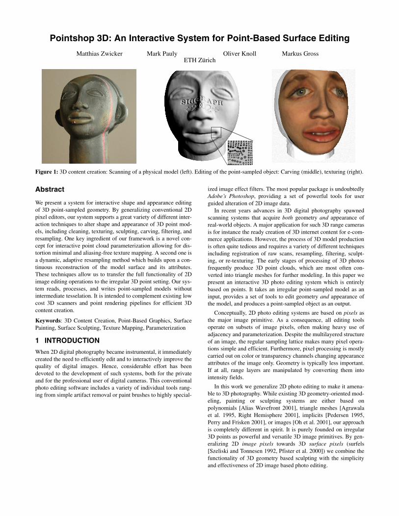
Figure 1: 3D content creation: Scanning of a physical model (left). Editing of the point-sampled object: Carving (middle), texturing (right).
Point samples provide an abstraction of geometry and appear-ance, since they discretize surface position and texture. However,as opposed to triangle meshes, they do not store information aboutlocal surface connectivity. Unlike 2D pixels, the absence of localtopology in combination with the irregularity of the sampling pat-tern poses great challenges to the design of 3D photo editing tools.We found that the two key ingredients for such tools are interactiveparameterization and dynamic resampling. For instance, surfacetexturing or carving both demand a flexible parameterization ofthe point cloud. In addition, points discretize geometry and appear-ance attributes at the same rate. Thus, fine-grain surface detailembossing with a high resolution depth map can lead to heavyaliasing and requires a dynamic adaptation of the sampling rate.
In the following, we will present a set of methods to solve theproblems stated above and integrate them into a versatile system.Specifically, our paper makes the following contributions:
Interactive parameterization (Section 3): By extending priorwork on triangle meshes [Levy 2001] we designed a novel methodfor distortion minimal parameterization of point clouds. The algo-rithm allows for constraints and enables users to interactivelyadapt the parameterization to input changes. A multigrid approachaccomplishes robust and efficient computation.
Dynamic resampling (Section 4): As a prerequisite, changes ofthe sampling rate demand a continuous reconstruction of themodel surface and of its attributes. To this end, we introduce anovel surface representation based on a parameterized scattereddata approximation. In addition, we propose a method whichdynamically adapts the number of samples to properly representfine geometric or appearance details. We combined our samplingstrategy with existing texture antialiasing techniques for point-sampled geometry [Zwicker et al. 2001].
Editing framework (Section 5): Our system provides a unifiedconceptual framework to edit 3D models. It supports a great vari-ety of individual tools to alter the geometry and appearance ofirregular point-sampled geometry. The scope of possible opera-tions goes well beyond the functionality of conventional 2D photoediting systems. We implemented re-texturing, sculpting, emboss-ing, and filtering, however, new effect filters can be added veryeasily. Overall, our system combines the efficiency of 2D photoediting with the functionality of 3D sculpting systems.
Pointshop 3D is not intended to be a point-based modeling sys-tem. As such, editing of the surface geometry is confined to nor-mal displacements and to moderate changes of the surfacestructure only. It is rather designed to complement low cost scan-ning devices [Eyetronics 2001] and point-based 3D viewers[Rusinkiewicz and Levoy 2000, Pfister et al. 2000, Arius3D 2001],yielding a powerful pipeline for efficient 3D content creation anddisplay. Pointshop 3D explores the usability of point primitives forsurface editing and constitutes an alternative to conventionalpolygonal mesh or splines based approaches. Since our algorithmsare based on -nearest neighbor search, input data with a substan-tial amount of noise or highly irregular sampling distribution, e.g.,as acquired by multiple merged range scans, can lead to instabili-ties. In these cases, the raw scans have to be resampled to a cleanpoint cloud, for example using distance fields [Curless and Levoy1996]. In general, suitable point data can be obtained by samplingisosurfaces of smooth implicit functions, which is easier thanextracting a good mesh. Volumetric methods such as MRI or CTscans can also provide clean input data to our system.
2 SYSTEM OVERVIEW
Our editing framework originates from the motivation to provide awide range of editing and processing techniques for point-sampled3D surfaces, similar to those found in common photo editing toolsfor 2D images. To give an overview of our system we will firstdescribe a typical photo editing operation on an abstract level.Then we will explain how these concepts can be transferred to sur-face editing, commenting on the fundamental differences betweenimages and surfaces. This will serve as a motivation for the tech-niques and algorithms described in the following sections. We alsointroduce an operator notation for general editing operations thatwill be used throughout the paper.
A 2D image can be considered a discrete sample of a continu-ous image function containing image attributes such as color ortransparency. Implicitly, the discrete image always representsthe continuous image, and image editing operations are performeddirectly on the discrete image. The continuous function can becomputed using a reconstruction operator whenever necessary.
We describe a general image editing operation as a function ofan original image and a brush image . The brush image is usedas a general tool to modify the original image. Depending on theconsidered operation, it may be interpreted as a paint brush or adiscrete filter, for example. The editing operation involves the fol-lowing steps: First, we need to specify a parameter mapping that aligns the image with the brush . For example, can bedefined as the translation that maps the pixel at the current mouseposition to the center of . Next, we have to establish a commonsampling grid for and , such that there is a one-to-one corre-spondence between the discrete samples. This requires a resam-pling operation that first reconstructs the continuous imagefunction and then samples this function on the common grid.Finally, the editing operator combines the image samples withthe brush samples using the one-to-one correspondence estab-lished before. We thus obtain the resulting discrete image as aconcatenation of the operators described above:
. (1)
Our goal is now to generalize the operator framework ofEquation (1) to irregular point-sampled surfaces, as illustrated inFigure 2.
Formally, we do this by replacing the discrete image by apoint-based surface . Hence, we represent a 3D object as a set ofirregular samples of its surface. Since the samples are a direct extension of image pixels, we will also call them sur-fels [Szeliski and Tonnesen 1992, Pfister et al. 2000]. As summa-rized in Table 1, each surfel stores appearance attributes, includingcolor, transparency, or material attributes, and shape attributes,such as position and normal. Let us now consider what effects thetransition from image to surface has on the individual terms ofEquation (1).
Parameterization . For photo editing, the parameter map-ping is usually specified by a simple, global 2D to 2D affinemapping, i.e., a combination of translation, scaling, and rotation.Mapping a manifold surface onto a 2D domain is much moreinvolved, however. In our system, the user interactively selectssubsets, or patches, of that are parameterized, as described inSection 3. In general, such a mapping leads to distortions that can-
k
I
I
I B
ΦI B Φ
BI B
Ψ
Ω
I′
I′ Ω Ψ Φ I( )( ) Ψ B( ),( )=
IS
S si = si
ΦΦ
S
not be avoided completely. In Section 3.2, we present an efficientmethod that automatically minimizes these distortions, and at thesame time lets the user intuitively control the mapping.
Resampling . Images are usually sampled on a regular grid,hence signal processing methods can be applied directly for resam-pling. However, the sampling distribution of surfaces is in generalirregular, requiring alternative methods for reconstruction andsampling. We apply a scattered data approximation approach forreconstructing a continuous function from the samples, asdescribed in Section 4. We also present a technique for resamplingour modified surface function onto irregular point clouds inSection 4.2. A great benefit of our system is that it supports adap-tive sampling, i.e., works on a dynamic structure. This allows us toconcentrate more samples in regions of high textural or geometricdetail, while smooth parts can be represented by fewer samples.
Editing . Once the parameterization is established and resam-pling has been performed, all computations take place on discretesamples in the 2D parameter domain. Hence we can apply the fullfunctionality of photo editing systems for texturing and texture fil-tering. However, since we are dealing with texture and geometry,the scope of operations is much broader. Additional editing opera-tors include sculpting, geometry filtering and simplification. Aswill be described in Section 5, all of these tools are based on the
same simple interface that specifies a tool by a set of bitmaps andfew additional parameters. For example, a sculpting tool is definedby a 2D displacement map, an alpha mask and an intrusion depth.
3 PARAMETERIZATION
In our system, the user interactively selects a subset of the sur-face , which we call a patch. We compute a parameterization ofthe patch that assigns parameter coordi-nates to each point in and then apply the editing operationon the parameterized patch. The user chooses between two typesof interaction schemes to select a patch and compute the parame-terization: A selection interaction for large patches, described inSections 3.1 and 3.2, and a brush interaction for small patches pre-sented in Section 3.3.
3.1 Selection Interaction
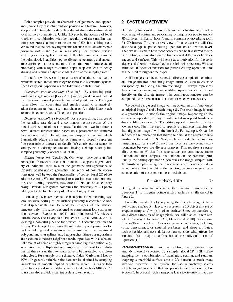
In this interaction scheme, the user triggers each step in the evalua-tion of Equation (1) separately. First, she marks an arbitrary sur-face patch using a dedicated selection tool and specifies a set offeature points. In a next step, she initiates a constrained minimumdistortion parameterization algorithm that uses the feature points,as described in Section 3.2. Then she typically performs a series ofediting operations on the parameterized patch, such as filtering ortexture mapping. This process is illustrated in Figure 3.
3.2 Minimum Distortion Parameterization
We describe a novel algorithm for computing minimum distortionparameterizations of point-based objects. Our approach is based onan objective function, similar to Levy’s method for polygonalmeshes [Levy 2001]. However, we then derive a discrete formula-tion for surfaces represented by scattered points without requiringany tesselation. We solve the resulting linear least squares problemefficiently using a multilevel approach by hierarchical clusteringof points.
Objective Function. Let us denote a continuous parameterizedsurface patch by . The patch is defined by a one-to-one map-ping which for each point
in represents a point on the surface:
. (2)
Figure 2: Overview of the operator framework for point-based sur-face editing.
Table 1: Attributes of a surface sample .
ATTRIBUTE ABBREVIATION
Position
Normal
Color
Transparency
Material properties
Parameterized patch Φ(S)
Resampled patch Ψ(Φ(S))
Brush Ψ(B)
Modified patch
Ψ
Ω
Original point-based surface
Φ
Modified point-based surface
si
xi
ni
ci
αi
mi
Ψ
Ω
Figure 3: Selection interaction: a) Patch selection and featurepoints. b) Texture map with feature points. c) Texture mapping.
SS
Φ:S 0 1,[ ] 0 1,[ ]×→ui si S
a) b) c)
XSX: 0 1,[ ] 0 1,[ ]× XS IR3∈→
u u v,( )T= 0 1,[ ] 0 1,[ ]× x x y z, ,( )T=
u 0 1,[ ] 0 1,[ ]× X u( )⇒∈x u( )y u( )z u( )
x XS∈= =
The mapping describes a parameterization of the surface, with its inverse. Our method computes a parameterization
that optimally adapts to the geometry of the surface, i.e., mini-mizes metric distortions. Additionally, the user is able to specify aset of point correspondences between points on the surface and points in the parameter domain , , to control the map-ping. This can be expressed as the following objective function:
, (3)
where , (4)
and . (5)
The first term in (3) represents the fitting error as the sum of thesquared deviations from the user specified data points. The secondterm measures the smoothness, or distortion, of the parameteriza-tion. At each surface point, integrates the squared curvatureof the parameterization in each radial direction using a local polarreparameterization . If is zero, the parameterizationat is a so called polar geodesic map, which preserves arc lengthin each radial direction [O'Neill 1966, Welch and Witkin 1994].With the parameter , the user additionally controls the relativeweight of the data fitting error and the smoothness constraint. Thedesired parameterization can be obtained by computing theminimum of the functional (3). We now describe how to set up andminimize (3) in the discrete case.
Discrete formulation. Given a set of distinct points onthe surface, our goal is to assign to each point a point in theparameter domain, such that the objective function is minimized.In other words, we are solving for the unknown discrete mapping
and hence we reformulate (3) by substituting theunknown for . Moreover, we assume that the parameteriza-tion is piecewise linear, thus the second derivative of is notdefined at the points in general. As an approximation, we dis-cretize the smoothness criterion by computing at each point thesquared difference of the first derivatives along a set of normalsections. This yields the following objective function :
, (6)
where is the number of points in the patch, specifies the setof normal sections, and and are unit vectors on the surfacegiven by the normal section.
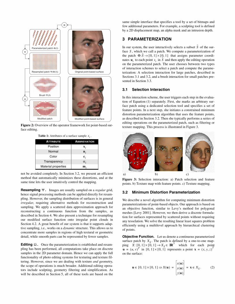
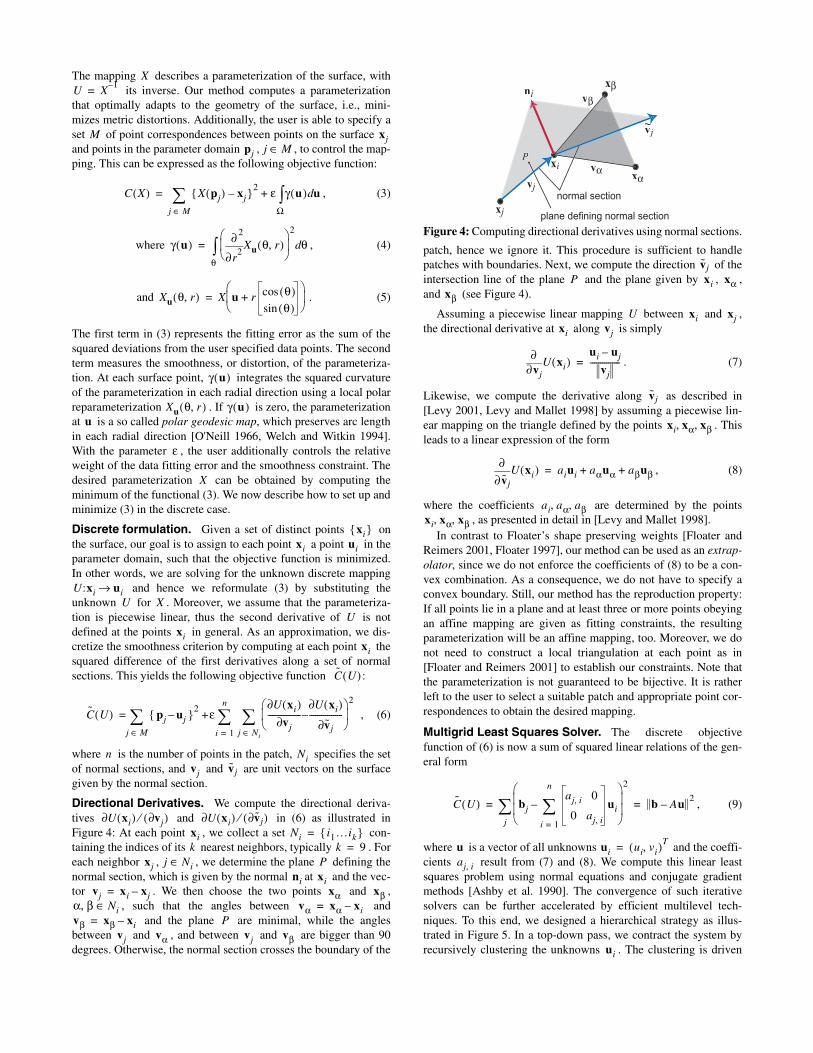
Directional Derivatives. We compute the directional deriva-tives and in (6) as illustrated inFigure 4: At each point , we collect a set con-taining the indices of its nearest neighbors, typically . Foreach neighbor , , we determine the plane defining thenormal section, which is given by the normal at and the vec-tor . We then choose the two points and ,
, such that the angles between and and the plane are minimal, while the angles
between and , and between and are bigger than 90degrees. Otherwise, the normal section crosses the boundary of the
patch, hence we ignore it. This procedure is sufficient to handlepatches with boundaries. Next, we compute the direction of theintersection line of the plane and the plane given by , ,and (see Figure 4).
Assuming a piecewise linear mapping between and ,the directional derivative at along is simply
. (7)
Likewise, we compute the derivative along as described in[Levy 2001, Levy and Mallet 1998] by assuming a piecewise lin-ear mapping on the triangle defined by the points . Thisleads to a linear expression of the form
, (8)
where the coefficients are determined by the points, as presented in detail in [Levy and Mallet 1998].
In contrast to Floater’s shape preserving weights [Floater andReimers 2001, Floater 1997], our method can be used as an extrap-olator, since we do not enforce the coefficients of (8) to be a con-vex combination. As a consequence, we do not have to specify aconvex boundary. Still, our method has the reproduction property:If all points lie in a plane and at least three or more points obeyingan affine mapping are given as fitting constraints, the resultingparameterization will be an affine mapping, too. Moreover, we donot need to construct a local triangulation at each point as in[Floater and Reimers 2001] to establish our constraints. Note thatthe parameterization is not guaranteed to be bijective. It is ratherleft to the user to select a suitable patch and appropriate point cor-respondences to obtain the desired mapping.
Multigrid Least Squares Solver. The discrete objectivefunction of (6) is now a sum of squared linear relations of the gen-eral form
, (9)
where is a vector of all unknowns and the coeffi-cients result from (7) and (8). We compute this linear leastsquares problem using normal equations and conjugate gradientmethods [Ashby et al. 1990]. The convergence of such iterativesolvers can be further accelerated by efficient multilevel tech-niques. To this end, we designed a hierarchical strategy as illus-trated in Figure 5. In a top-down pass, we contract the system byrecursively clustering the unknowns . The clustering is driven
XU X
1–=
M xjpj j M∈
C X( ) X pj( ) xj– 2 ε γ u( ) ud
Ω∫+
j M∈∑=
γ u( )r
2
2
∂∂
Xu θ r,( ) 2
θd
θ∫=
Xu θ r,( ) X u r θ( )cos
θ( )sin+
=
γ u( )
Xu θ r,( ) γ u( )u
ε
X
xi xi ui
U:xi ui→U X
Uxi
xi
C U( )
C U( ) pj uj– 2 εU xi( )∂
vj∂-----------------
U xi( )∂
vj∂-----------------–
2
j Ni∈∑
i 1=
n
∑+
j M∈∑=
n Nivj vj
U xi( ) vj∂( )⁄∂ U xi( ) vj∂( )⁄∂xi Ni i1…ik =k k 9=
xj j Ni∈ Pni xi
vj xi xj–= xα xβα β, Ni∈ vα xα xi–=vβ xβ xi–= P
vj vα vj vβ
Figure 4: Computing directional derivatives using normal sections.
i
xj
xα
xβ
vjvj
v~~jvj
vα
vβ
P
ni
plane defining normal section
normal section
vjP xi xα
xβ
U xi xjxi vj
vj∂∂
U xi( )ui uj–
vj---------------=
vj
xi xα xβ, ,
vj∂∂
U xi( ) aiui aαuα aβuβ+ +=
ai aα aβ, ,xi xα xβ, ,
C U( ) bjaj i, 0
0 aj i,
ui
i 1=
n
∑– 2
j∑ b Au–
2= =
u ui ui vi,( )T=
aj i,
ui
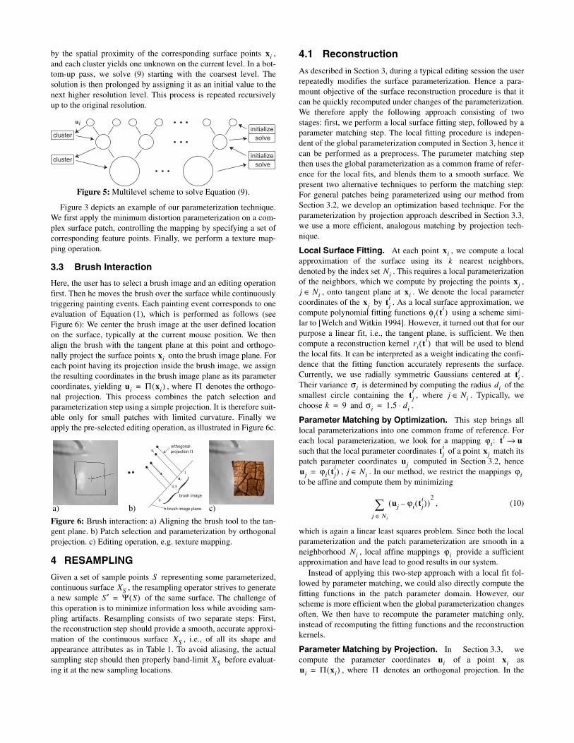
by the spatial proximity of the corresponding surface points ,and each cluster yields one unknown on the current level. In a bot-tom-up pass, we solve (9) starting with the coarsest level. Thesolution is then prolonged by assigning it as an initial value to thenext higher resolution level. This process is repeated recursivelyup to the original resolution.
Figure 3 depicts an example of our parameterization technique.We first apply the minimum distortion parameterization on a com-plex surface patch, controlling the mapping by specifying a set ofcorresponding feature points. Finally, we perform a texture map-ping operation.
3.3 Brush Interaction
Here, the user has to select a brush image and an editing operationfirst. Then he moves the brush over the surface while continuouslytriggering painting events. Each painting event corresponds to oneevaluation of Equation (1), which is performed as follows (seeFigure 6): We center the brush image at the user defined locationon the surface, typically at the current mouse position. We thenalign the brush with the tangent plane at this point and orthogo-nally project the surface points onto the brush image plane. Foreach point having its projection inside the brush image, we assignthe resulting coordinates in the brush image plane as its parametercoordinates, yielding , where denotes the orthogo-nal projection. This process combines the patch selection andparameterization step using a simple projection. It is therefore suit-able only for small patches with limited curvature. Finally weapply the pre-selected editing operation, as illustrated in Figure 6c.
4 RESAMPLING
Given a set of sample points representing some parameterized,continuous surface , the resampling operator strives to generatea new sample of the same surface. The challenge ofthis operation is to minimize information loss while avoiding sam-pling artifacts. Resampling consists of two separate steps: First,the reconstruction step should provide a smooth, accurate approxi-mation of the continuous surface , i.e., of all its shape andappearance attributes as in Table 1. To avoid aliasing, the actualsampling step should then properly band-limit before evaluat-ing it at the new sampling locations.
4.1 Reconstruction
As described in Section 3, during a typical editing session the userrepeatedly modifies the surface parameterization. Hence a para-mount objective of the surface reconstruction procedure is that itcan be quickly recomputed under changes of the parameterization.We therefore apply the following approach consisting of twostages: first, we perform a local surface fitting step, followed by aparameter matching step. The local fitting procedure is indepen-dent of the global parameterization computed in Section 3, hence itcan be performed as a preprocess. The parameter matching stepthen uses the global parameterization as a common frame of refer-ence for the local fits, and blends them to a smooth surface. Wepresent two alternative techniques to perform the matching step:For general patches being parameterized using our method fromSection 3.2, we develop an optimization based technique. For theparameterization by projection approach described in Section 3.3,we use a more efficient, analogous matching by projection tech-nique.
Local Surface Fitting. At each point , we compute a localapproximation of the surface using its nearest neighbors,denoted by the index set . This requires a local parameterizationof the neighbors, which we compute by projecting the points ,
, onto tangent plane at . We denote the local parametercoordinates of the by . As a local surface approximation, wecompute polynomial fitting functions using a scheme simi-lar to [Welch and Witkin 1994]. However, it turned out that for ourpurpose a linear fit, i.e., the tangent plane, is sufficient. We thencompute a reconstruction kernel that will be used to blendthe local fits. It can be interpreted as a weight indicating the confi-dence that the fitting function accurately represents the surface.Currently, we use radially symmetric Gaussians centered at .Their variance is determined by computing the radius of thesmallest circle containing the , where . Typically, wechoose and .
Parameter Matching by Optimization. This step brings alllocal parameterizations into one common frame of reference. Foreach local parameterization, we look for a mapping such that the local parameter coordinates of a point match itspatch parameter coordinates computed in Section 3.2, hence
, . In our method, we restrict the mappings to be affine and compute them by minimizing
, (10)
which is again a linear least squares problem. Since both the localparameterization and the patch parameterization are smooth in aneighborhood , local affine mappings provide a sufficientapproximation and have lead to good results in our system.
Instead of applying this two-step approach with a local fit fol-lowed by parameter matching, we could also directly compute thefitting functions in the patch parameter domain. However, ourscheme is more efficient when the global parameterization changesoften. We then have to recompute the parameter matching only,instead of recomputing the fitting functions and the reconstructionkernels.
Parameter Matching by Projection. In Section 3.3, wecompute the parameter coordinates of a point as
, where denotes an orthogonal projection. In the
Figure 5: Multilevel scheme to solve Equation (9).
Figure 6: Brush interaction: a) Aligning the brush tool to the tan-gent plane. b) Patch selection and parameterization by orthogonalprojection. c) Editing operation, e.g. texture mapping.
xi
ui
cluster solve
initialize
solve
initializecluster
xi
ui Π xi( )= Π
xi
ui
0
1
0.5 brush image
brush image plane
orthogonal
projection Π
b)a) c)
SXS
S′ Ψ S( )=
XS
XS
xik
Nixj
j Ni∈ xixj tj
i
φi ti( )
ri ti( )
tii
σi ditji
j Ni∈k 9= σi 1.5 di⋅=
ϕi: ti u→
tji xj
ujuj ϕi tj
i( )= j Ni∈ ϕi
uj ϕi tji( )–( )
2
j Ni∈∑
Ni ϕi
ui xiui Π xi( )= Π
same way, we can then project the fitting functions to the patchparameter domain, i.e., , thus .Inverting this projection amounts to ray-tracing the fitting func-tions. For linear basis functions, this can be implemented by anefficient scan conversion.
Blending the Fitting Functions. After establishing the map-pings from the local parameterizations to the patch parameterdomain, we define fitting functions and reconstruction ker-nels in the patch parameter domain as and . We now obtain a continuous surfacefunction as the weighted sum
. (11)
of fitting functions and reconstruction kernels .
Our approach is similar in spirit to the construction of point setsurfaces introduced in [Alexa 2001], in that both methods use localparameterizations and polynomials to approximate the surface.However, instead of implicitly defining the surface by a projectionoperator, we blend the local approximations using a global param-eterization.
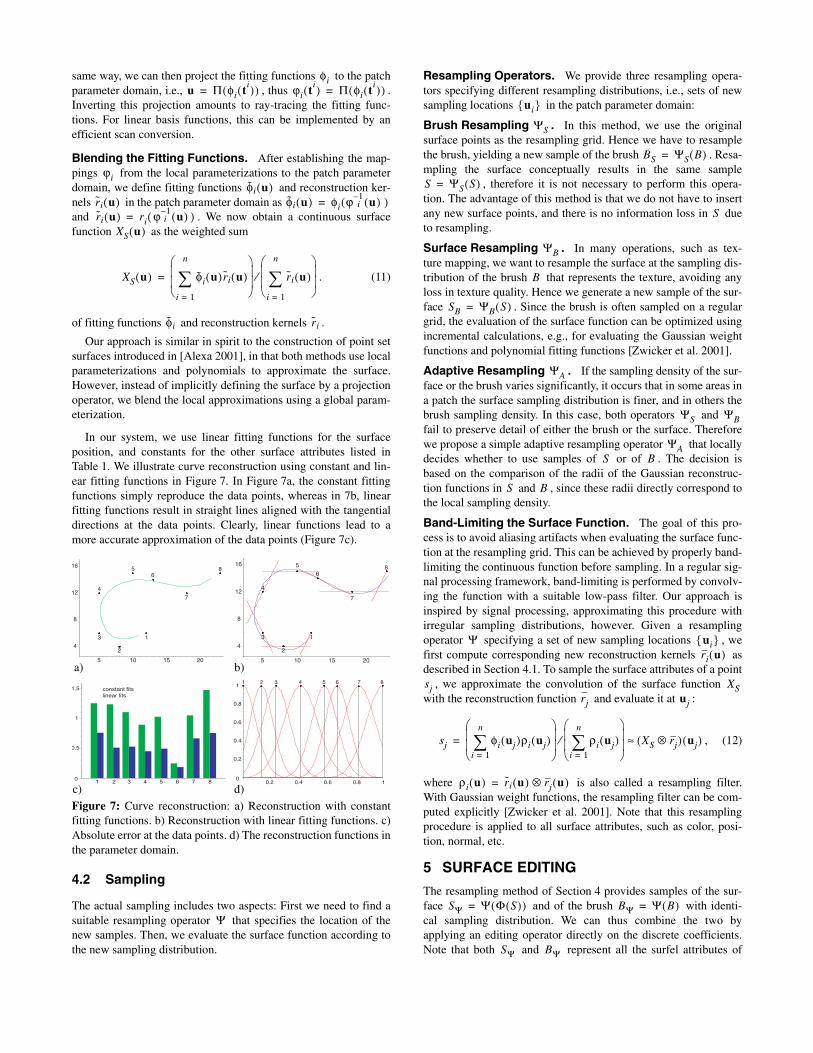
In our system, we use linear fitting functions for the surfaceposition, and constants for the other surface attributes listed inTable 1. We illustrate curve reconstruction using constant and lin-ear fitting functions in Figure 7. In Figure 7a, the constant fittingfunctions simply reproduce the data points, whereas in 7b, linearfitting functions result in straight lines aligned with the tangentialdirections at the data points. Clearly, linear functions lead to amore accurate approximation of the data points (Figure 7c).
4.2 Sampling
The actual sampling includes two aspects: First we need to find asuitable resampling operator that specifies the location of thenew samples. Then, we evaluate the surface function according tothe new sampling distribution.
Resampling Operators. We provide three resampling opera-tors specifying different resampling distributions, i.e., sets of newsampling locations in the patch parameter domain:
Brush Resampling . In this method, we use the originalsurface points as the resampling grid. Hence we have to resamplethe brush, yielding a new sample of the brush . Resa-mpling the surface conceptually results in the same sample
, therefore it is not necessary to perform this opera-tion. The advantage of this method is that we do not have to insertany new surface points, and there is no information loss in dueto resampling.
Surface Resampling . In many operations, such as tex-ture mapping, we want to resample the surface at the sampling dis-tribution of the brush that represents the texture, avoiding anyloss in texture quality. Hence we generate a new sample of the sur-face . Since the brush is often sampled on a regulargrid, the evaluation of the surface function can be optimized usingincremental calculations, e.g., for evaluating the Gaussian weightfunctions and polynomial fitting functions [Zwicker et al. 2001].
Adaptive Resampling . If the sampling density of the sur-face or the brush varies significantly, it occurs that in some areas ina patch the surface sampling distribution is finer, and in others thebrush sampling density. In this case, both operators and fail to preserve detail of either the brush or the surface. Thereforewe propose a simple adaptive resampling operator that locallydecides whether to use samples of or of . The decision isbased on the comparison of the radii of the Gaussian reconstruc-tion functions in and , since these radii directly correspond tothe local sampling density.
Band-Limiting the Surface Function. The goal of this pro-cess is to avoid aliasing artifacts when evaluating the surface func-tion at the resampling grid. This can be achieved by properly band-limiting the continuous function before sampling. In a regular sig-nal processing framework, band-limiting is performed by convolv-ing the function with a suitable low-pass filter. Our approach isinspired by signal processing, approximating this procedure withirregular sampling distributions, however. Given a resamplingoperator specifying a set of new sampling locations , wefirst compute corresponding new reconstruction kernels asdescribed in Section 4.1. To sample the surface attributes of a point
, we approximate the convolution of the surface function with the reconstruction function and evaluate it at :
, (12)
where is also called a resampling filter.With Gaussian weight functions, the resampling filter can be com-puted explicitly [Zwicker et al. 2001]. Note that this resamplingprocedure is applied to all surface attributes, such as color, posi-tion, normal, etc.
5 SURFACE EDITING
The resampling method of Section 4 provides samples of the sur-face and of the brush with identi-cal sampling distribution. We can thus combine the two byapplying an editing operator directly on the discrete coefficients.Note that both and represent all the surfel attributes of
Figure 7: Curve reconstruction: a) Reconstruction with constantfitting functions. b) Reconstruction with linear fitting functions. c)Absolute error at the data points. d) The reconstruction functions inthe parameter domain.
φiu Π φi ti( )( )= ϕi ti( ) Π φi ti( )( )=
ϕiφi u( )
ri u( ) φi u( ) φi ϕ 1–i u( )( )=
ri u( ) ri ϕ 1–i u( )( )=
XS u( )
XS u( ) φi˜ u( ) ri u( )i 1=
n
∑
ri u( )i 1=
n
∑
⁄=
φi ri
0
0.2
0.4
0.6
0.8
1
10.2 0.4 0.6 0.8
1 2 3 4 5 6 7 8
4
8
12
16
5 10 15 20
1
2
3
4
56
7
8
0
0.5
1
1.5
1 4 5 6 7 82 3
constant fits
linear fits
4
8
12
16
5 10 15 20
1
2
3
4
56
7
8
c)
a) b)
d)
Ψ
ui
ΨS
BS ΨS B( )=
S ΨS S( )=
S
ΨB
B
SB ΨB S( )=
ΨA
ΨS ΨB
ΨAS B
S B
Ψ ui ri u( )
sj XSrj uj
sj φi uj( )ρi uj( )i 1=
n
∑
ρi uj( )i 1=
n
∑
⁄ XS rj⊗( ) uj( )≈=
ρi u( ) ri u( ) rj u( )⊗=
SΨ Ψ Φ S( )( )= BΨ Ψ B( )=
SΨ BΨ
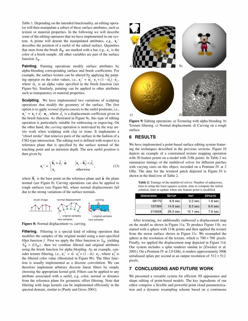
Table 1. Depending on the intended functionality, an editing opera-tor will then manipulate a subset of these surface attributes, such astexture or material properties. In the following we will describesome of the editing operators that we have implemented in our sys-tem. A prime will denote the manipulated attributes, e.g., describes the position of a surfel of the edited surface. Quantitiesthat stem from the brush are marked with a bar, e.g., is thecolor of a brush sample. All other variables are part of the surfacefunction .
Painting. Painting operations modify surface attributes byalpha-blending corresponding surface and brush coefficients. Forexample, the surface texture can be altered by applying the paint-ing operator on the color values, i.e., ,where is an alpha value specified in the brush function (seeFigure 9a). Similarly, painting can be applied to other attributessuch as transparency or material properties.
Sculpting. We have implemented two variations of sculptingoperations that modify the geometry of the surface. The firstoption is to apply normal displacements to the surfel positions, i.e.,
, where is a displacement coefficient given inthe brush function. As illustrated in Figure 9c, this type of editingoperation is particularly suitable for embossing or engraving. Onthe other hand, the carving operation is motivated by the way art-ists work when sculpting with clay or stone. It implements a“chisel stroke” that removes parts of the surface in the fashion of aCSG-type intersection. The editing tool is defined with respect to areference plane that is specified by the surface normal of thetouching point and an intrusion depth. The new surfel position isthen given by
, (13)
where is the base point on the reference plane and the planenormal (see Figure 8). Carving operations can also be applied torough surfaces (see Figure 9d), where normal displacements faildue to the strong variations of the surface normals.
Filtering. Filtering is a special kind of editing operation thatmodifies the samples of the original model using a user-specifiedfilter function . First we apply the filter function to yielding
, then we combine filtered and original attributesusing the brush function for alpha blending. As an example, con-sider texture filtering, i.e., , where isthe filtered color value (illustrated in Figure 9b). The filter func-tion is usually implemented as a discrete convolution. We cantherefore implement arbitrary discrete linear filters by simplychoosing the appropriate kernel grid. Filters can be applied to anyattribute associated with a surfel, e.g. color, normal or distancefrom the reference plane for geometric offset filtering. Note thatfiltering with large kernels can be implemented efficiently in thespectral domain, similar to [Pauly and Gross 2001].
6 RESULTS
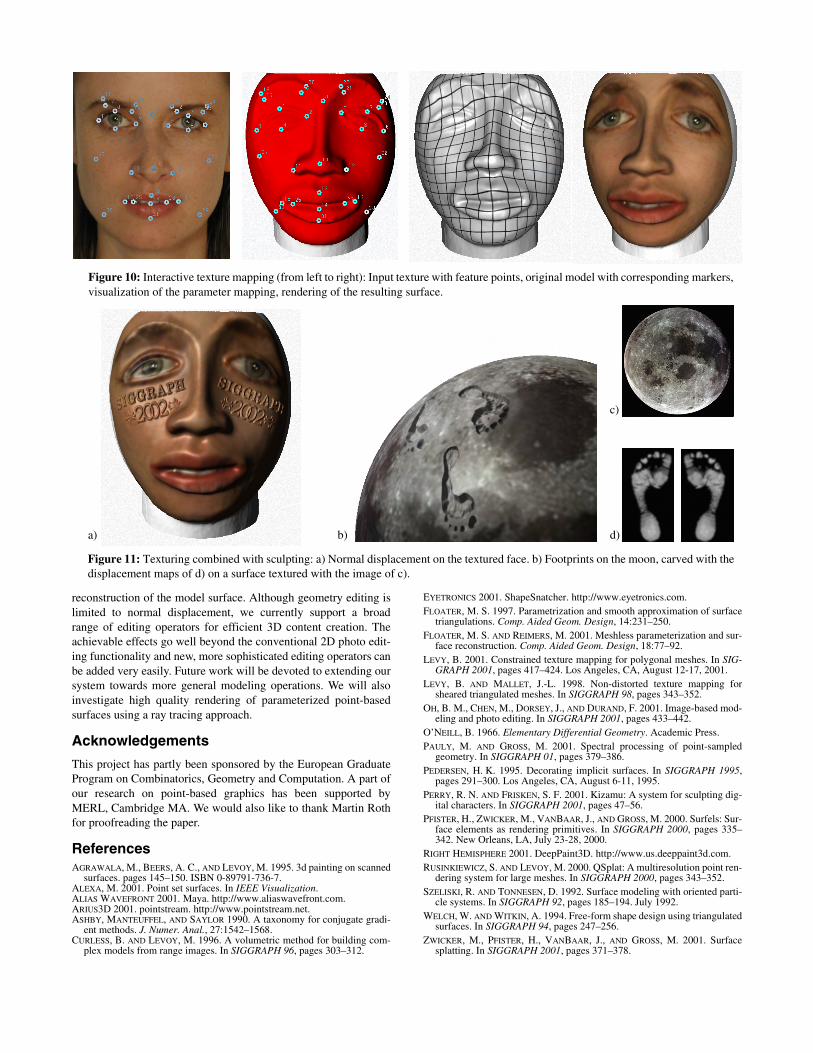
We have implemented a point-based surface editing system featur-ing the techniques described in the previous sections. Figure 10depicts an example of a constrained texture mapping operationwith 30 feature points on a model with 218k points. In Table 2 wesummarize timings of the multilevel solver for different patcheswith varying sizes on this object, recorded on a Pentium IV at 2GHz. The data for the textured patch depicted in Figure 10 isshown in the third row of Table 2.
After texturing, we additionally embossed a displacement mapon the model as shown in Figure 11a. To produce Figure 11b, westarted with a sphere with 114k points and then applied the texturefrom the moon surface shown in Figure 11c. We resampled thesphere at the resolution of the texture, which is pixels.Finally, we applied the displacement map depicted in Figure 11d.Our system includes a splat renderer similar to [Zwicker et al.2001]. On a Pentium IV at 2.0 GHz, it renders approximately 500kantialiased splats per second at an output resolution of pixels.
7 CONCLUSIONS AND FUTURE WORK
We presented a versatile system for efficient 3D appearance andshape editing of point-based models. The key ingredients of oureditor comprise a flexible and powerful point cloud parameteriza-tion and a dynamic resampling scheme based on a continuous
Figure 8: Normal displacement vs. carving.
xi′
BΨ ci
SΨ
ci′ αi ci 1 αi–( ) ci⋅+⋅=αi
xi′ xi di ni⋅+= di
xi′bi di n⋅+ xi bi– di<
xi otherwise
=
bi n
brush image normal displacement carving
original samplesnew samples
original samplesnew samples
b_in
_
f SΨSΨ
ff SΨ( )=
ci′ α cif
1 α–( ) ci⋅+⋅= cif
Figure 9: Editing operations: a) Texturing with alpha blending. b)Texture filtering. c) Normal displacement. d) Carving on a roughsurface.
Table 2: Timings of the multilevel solver: Number of unknowns, time to setup the least squares system, time to compute the initial solution, time to update when one feature point is modified.
UNKNOWNS SETUP INIT UPDATE
58170 6.9 sec. 2.2 sec. 1.8 sec.
107394 14.9 sec. 8.3 sec. 6.6 sec.
215628 26.3 sec. 12.1 sec. 7.6 sec.
a) b)
c) d)
700 700×
512 512×
reconstruction of the model surface. Although geometry editing islimited to normal displacement, we currently support a broadrange of editing operators for efficient 3D content creation. Theachievable effects go well beyond the conventional 2D photo edit-ing functionality and new, more sophisticated editing operators canbe added very easily. Future work will be devoted to extending oursystem towards more general modeling operations. We will alsoinvestigate high quality rendering of parameterized point-basedsurfaces using a ray tracing approach.
Acknowledgements
This project has partly been sponsored by the European GraduateProgram on Combinatorics, Geometry and Computation. A part ofour research on point-based graphics has been supported byMERL, Cambridge MA. We would also like to thank Martin Rothfor proofreading the paper.
ReferencesAGRAWALA, M., BEERS, A. C., AND LEVOY, M. 1995. 3d painting on scanned
surfaces. pages 145–150. ISBN 0-89791-736-7.ALEXA, M. 2001. Point set surfaces. In IEEE Visualization.ALIAS WAVEFRONT 2001. Maya. http://www.aliaswavefront.com.ARIUS3D 2001. pointstream. http://www.pointstream.net.ASHBY, MANTEUFFEL, AND SAYLOR 1990. A taxonomy for conjugate gradi-
ent methods. J. Numer. Anal., 27:1542–1568.CURLESS, B. AND LEVOY, M. 1996. A volumetric method for building com-
plex models from range images. In SIGGRAPH 96, pages 303–312.
EYETRONICS 2001. ShapeSnatcher. http://www.eyetronics.com.FLOATER, M. S. 1997. Parametrization and smooth approximation of surface
triangulations. Comp. Aided Geom. Design, 14:231–250.FLOATER, M. S. AND REIMERS, M. 2001. Meshless parameterization and sur-
face reconstruction. Comp. Aided Geom. Design, 18:77–92.LEVY, B. 2001. Constrained texture mapping for polygonal meshes. In SIG-
GRAPH 2001, pages 417–424. Los Angeles, CA, August 12-17, 2001.LEVY, B. AND MALLET, J.-L. 1998. Non-distorted texture mapping for
sheared triangulated meshes. In SIGGRAPH 98, pages 343–352.OH, B. M., CHEN, M., DORSEY, J., AND DURAND, F. 2001. Image-based mod-
eling and photo editing. In SIGGRAPH 2001, pages 433–442.O’NEILL, B. 1966. Elementary Differential Geometry. Academic Press.PAULY, M. AND GROSS, M. 2001. Spectral processing of point-sampled
geometry. In SIGGRAPH 01, pages 379–386.PEDERSEN, H. K. 1995. Decorating implicit surfaces. In SIGGRAPH 1995,
pages 291–300. Los Angeles, CA, August 6-11, 1995.PERRY, R. N. AND FRISKEN, S. F. 2001. Kizamu: A system for sculpting dig-
ital characters. In SIGGRAPH 2001, pages 47–56.PFISTER, H., ZWICKER, M., VANBAAR, J., AND GROSS, M. 2000. Surfels: Sur-
face elements as rendering primitives. In SIGGRAPH 2000, pages 335–342. New Orleans, LA, July 23-28, 2000.
RIGHT HEMISPHERE 2001. DeepPaint3D. http://www.us.deeppaint3d.com.RUSINKIEWICZ, S. AND LEVOY, M. 2000. QSplat: A multiresolution point ren-
dering system for large meshes. In SIGGRAPH 2000, pages 343–352.SZELISKI, R. AND TONNESEN, D. 1992. Surface modeling with oriented parti-
cle systems. In SIGGRAPH 92, pages 185–194. July 1992.WELCH, W. AND WITKIN, A. 1994. Free-form shape design using triangulated
surfaces. In SIGGRAPH 94, pages 247–256.ZWICKER, M., PFISTER, H., VANBAAR, J., AND GROSS, M. 2001. Surface
splatting. In SIGGRAPH 2001, pages 371–378.
Figure 10: Interactive texture mapping (from left to right): Input texture with feature points, original model with corresponding markers,visualization of the parameter mapping, rendering of the resulting surface.
b)
c)
d)
Figure 11: Texturing combined with sculpting: a) Normal displacement on the textured face. b) Footprints on the moon, carved with thedisplacement maps of d) on a surface textured with the image of c).
a)