Embed Size (px)
Citation preview
Interactive 3D Building Modeling Using a Hierarchical Representation
Sung Chun Lee* and Ram. Nevatia*
*Institute for Robotics and Intelligent Systems,University of Southern California
Los Angeles, California 90089, USA{sungchun|nevatia}@usc.edu
AbstractModeling and visualization of city scenes is important
for many applications including entertainment and urbanmission planning. Models covering wide areas can be effi-ciently constructed from aerial images. However, onlyroof details are visible from aerial views and ground viewsare needed to provide details of the building facades forhigh quality fly-through visualization or simulation appli-cations. Different data sources provide different levels ofnecessary detail knowledge. We need a method that inte-grates the various levels of data. We propose a hierarchi-cal representation of 3D building models for urban areasthat integrates different data sources including aerial andground view images. Each data source gives us differentdetails and each level of the model has its own applicationas well. Through the hierarchical representation of 3Dbuilding models, large area site modeling can be doneefficiently and cost-effectively. This proposal suggests effi-cient approaches for acquiring each level model and dem-onstrates some results of each level including theintegration results.
1 Introduction
Accurate 3D building models for a city are useful fora variety of applications such as 2D and 3D GIS, fly-through rendering, and simulation for mission planning.Each application requires different aspects of the 3Dbuilding model. 2D GIS needs the roof boundary of build-ings and 3D GIS requires the height and roof boundary ofbuildings. Fly-through rendering demands textures ofbuilding facades in addition to the 3D building model.Furthermore, a walk-through or high-quality renderingapplication requires detailed 3D structural description of abuilding facade.
These different levels of information for 3D buildingmodels are computed or obtained from different datasources. For example, information such as the roof bound-
ary or height can be obtained by using aerial images orLIDAR (LIght Detection And Ranging) data. Facadeinformation such as its texture, descriptive information, ordetailed 3D structure, can be computed from multipleground view images.
A variety of computer vision problems arise in theprocess of obtaining 3D building models. The first is the3D building reconstruction to acquire the initials. The cre-ation of 3D building models from aerial view analysis hasbeen researched extensively [1, 2, 3]. Second, we have toperform calibration, or pose estimation, of uncalibratedground view images to obtain facade related information.Even though general camera calibration is still an openproblem in computer vision, the calibration process forground view images of an architectural scene can besolved by using the regularity knowledge of buildingstructure such as an orthogonality of vertical and horizon-tal lines and parallelism of roof and ground lines.
In this paper, we attempt to integrate the processes ofobtaining the different level knowledge for building mod-els from various data sources by deriving a hierarchicalrepresentation of a 3D building model. To implement hier-archical representations for 3D building models, weexploit the concept of Level Of Detail (LOD) from virtualreality literature to represent the different level of knowl-edge. The LOD is used for storing a number of representa-tions of an object, where the complexity of eachrepresentation is varied so that an approximate model canbe selected according to the complexity of the application.In this paper, we define the representations of 3D buildingmodels as followings:
Level 1: Structural information of buildingLevel 2: Facade texture informationLevel 3: Detailed geometry of building facade
The concept of the hierarchical representation forbuilding models is illustrated in Figure 1.
1.1 Related Work
Recently, ground view based approaches for obtain-ing full geometric information of 3D building models,have been popular since data sources such as multipleground images or video sequences are more readilyobtained than aerial view images. In addition, the groundview images provide high resolution modeling results.
In [4], data sources are multiple ground view imagesand the polyhedral primitive 3D models. The drawback ofthis approach, however, is that it is hard to scale to largearea site modeling because laborious user interactions arerequired for a large number of models.
New approaches of integrating more than one datasource such as multiple ground view images and GPS datahave been attempted to model 3D buildings [5, 6]. Thisapproach can be applied to modeling a relatively large sitedue to the global positioning capability supported by aGPS device, but it is limited to model only simple shapebuildings and does not capture the roof structure.
Werner and Zisserman [7] recently tried to recon-struct the detail structure of building facade by fittingprimitive blocks. Performance of their method is highlydependent on the accuracy of line matching.
A Bayesian approach is used to reconstruct 3D build-ing models in Cipolla at el. [8]. They estimate relativerotation between 3D models and camera by using threeorthogonal vanishing points. This method requires vanish-ing points from orthogonal families of lines. Robertsonand Cipolla [9] add a geo reference functionality to theirprevious work [8] by exploiting a 2D map. Given theextracted layers on building facade, Dick at el. [10] recon-struct the 3D facade primitives using prior 3D primitiveblocks based on a Bayesian framework. Recently, Dick atel. [11] improve their previous method by adding morecomponents such as alignment and symmetry among thefacade primitives by exploiting architectural knowledge.However, these approaches depend on strong priors,
which makes their algorithms have a limitation on scal-ability.
Stamos and Allen [12] use dense range data to recon-struct the detailed 3D building models by the swept multi-ple high precision range data. Range data allows makingdetailed models but it expensive and cumbersome toacquire. Fruh and Zakhor [13] use ground level rangedata, ground view images, and aerial view photographs(including digital roadmap). Their approach fuses differ-ent data to compensate for the accumulated errors of rangedata. However, the generated 3D building models are amesh structure and do not make the structure explicit.
1.2 Overview
Using a hierarchical building representation, thereconstruction process of more complex level models isaided by simpler level models. The hierarchical buildingrepresentation reduces the complexity of computer visionproblems and makes the task of generating building mod-els feasible.
For level 1 model (simpler model), we use the knowl-edge that a flat roof building is likely to have the roof par-allel to the ground and walls perpendicular to the ground.The representation of level 1 model consists of the 2Droof boundary and its height. As shown in Figure 2, level1 models are acquired using this knowledge, by a humanor an automatic process from multiple aerial view imagesas will be explained in Section 2.
To obtain level 2 model, we exploit the knowledgefrom level 1 models, which is the 3D information of wire-frame building models such as its 3D vertices, boundarylines, and faces. With 3D building models and automati-cally or interactively extracted vanishing points, we esti-mate the pose of the ground view camera using only two3D to 2D point correspondences, as explained in Section3.
We use the knowledge that the orientation of thedetailed structures of building facade (level 3 models) isperpendicular to the building facade that contains them.Then, we use the calibrated ground view camera informa-tion from level 2 and 3D model information from level 1to reduce user interactions for creating level 3 models, asdescribed in Section 4.
2 Acquisition of Level 1 models
In this section, we describe a cost-effective user inter-active method to reconstruct a 3D architectural wireframemodels (level 1 models) from multiple aerial images forurban or suburban site modeling.
(a) Level 1 model (b) Level 2 model
(c) Level 3 modelFigure 1. A hierarchical building representation.
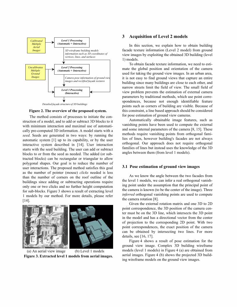
The method consists of processes to initiate the con-struction of a model, and to add or subtract 3D blocks to itwith minimum interaction and maximal use of automati-cally pre-computed 3D information. A model starts with aseed. Seeds are generated in two ways: by running theautomatic system [1] up to its capability, or by the userinteractive system described in [14]. User interactionstarts with the seed building. The user can add or subtractblocks to or from the seed as needed. The added (or sub-tracted blocks) can be rectangular or triangular to allowpolygonal shapes. Our goal is to reduce the number ofuser interactions. The proposed method satisfies this goalas the number of pointer (mouse) clicks needed is lessthan the number of corners on the roof outline of thebuildings since adding or subtracting operations requireonly one or two clicks and no further height computationfor sub-blocks. Figure 3 shows a result of extracting level1 models by our method. For more details, please refer[14].
3 Acquisition of Level 2 models
In this section, we explain how to obtain buildingfacade texture information (Level 2 model) from groundview images by exploiting the obtained 3D building (level1) models.
To obtain facade texture information, we need to esti-mate the global position and orientation of the cameraused for taking the ground view images. In an urban area,it is not easy to find ground views that capture an entirebuilding since many buildings are close to each other, andnarrow streets limit the field of view. The small field ofview problem prevents the estimation of external cameraparameters by traditional methods, which use point corre-spondences, because not enough identifiable featurepoints such as corners of building are visible. Because ofthis constraint, a line based approach should be consideredfor pose estimation of ground view cameras.
Automatically obtainable image features, such asvanishing points have been used to compute the externaland some internal parameters of the camera [8, 15]. Thesemethods require vanishing points from orthogonal fami-lies of lines, however building's facades are not alwaysorthogonal. Our approach does not require orthogonalfamilies of lines but instead uses the knowledge of the 3Dangles between them (from level 1 models).
3.1 Pose estimation of ground view images
As we know the angle between the two facades fromthe level 1 models, we can infer a real orthogonal vanish-ing point under the assumption that the principal point ofthe camera is known (to be the center of the image). Threeinferred orthogonal vanishing points are used to computethe camera rotation [8].
Given the external rotation matrix and one 3D to 2Dpoint correspondence, the 3D position of the camera cen-ter must be on the 3D line, which intersects the 3D pointin the model and has a directional vector from the centerof projection to the corresponding 2D point. With twopoint correspondences, the exact position of the cameracan be obtained by intersecting two lines. For moredetails, see [16, 17].
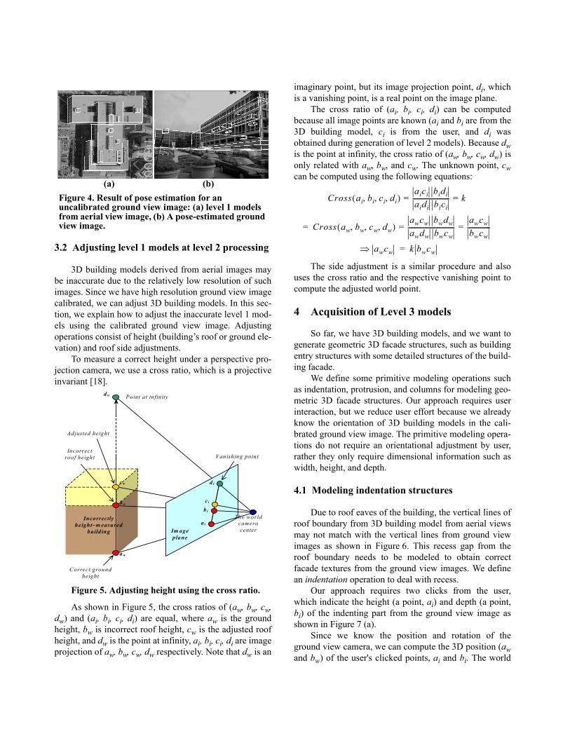
Figure 4 shows a result of pose estimation for theground view image. Complex 3D building wireframemodels (level 1 models) in Figure 4 (a) are obtained fromaerial images. Figure 4 (b) shows the projected 3D build-ing wireframe models on the ground view images.
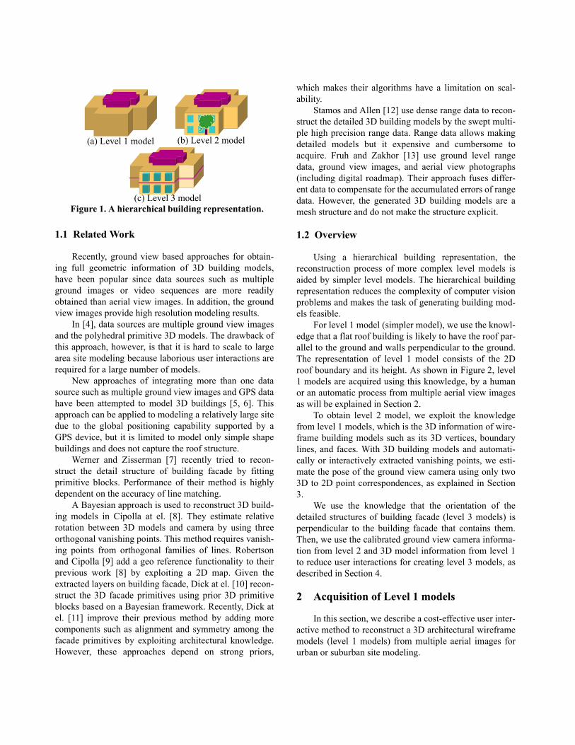
Level 1 Processing (Automatic + Interactive)
Level 2 Processing (Automatic + Interactive)
Level 3 Processing (Interactive)
Calibrated Multiple Aerial Images
Uncalibrated Multiple Ground Images
3D wireframe building models information such as 3D coordinates of vertices, lines, and surfaces
Camera pose information of ground view images and rectified façade textures
Detailed façade structure of 3D buildings
Figure 2. The overview of the proposed system.
(a) An aerial view image (b) Level 1 modelsFigure 3. Extracted level 1 models from aerial images.
3.2 Adjusting level 1 models at level 2 processing
3D building models derived from aerial images maybe inaccurate due to the relatively low resolution of suchimages. Since we have high resolution ground view imagecalibrated, we can adjust 3D building models. In this sec-tion, we explain how to adjust the inaccurate level 1 mod-els using the calibrated ground view image. Adjustingoperations consist of height (building’s roof or ground ele-vation) and roof side adjustments.
To measure a correct height under a perspective pro-jection camera, we use a cross ratio, which is a projectiveinvariant [18].
As shown in Figure 5, the cross ratios of (aw, bw, cw,dw) and (ai, bi, ci, di) are equal, where aw is the groundheight, bw is incorrect roof height, cw is the adjusted roofheight, and dw is the point at infinity, ai, bi, ci, di are imageprojection of aw, bw, cw, dw respectively. Note that dw is an
imaginary point, but its image projection point, di, whichis a vanishing point, is a real point on the image plane.
The cross ratio of (ai, bi, ci, di) can be computedbecause all image points are known (ai and bi are from the3D building model, ci is from the user, and di wasobtained during generation of level 2 models). Because dwis the point at infinity, the cross ratio of (aw, bw, cw, dw) isonly related with aw, bw, and cw. The unknown point, cwcan be computed using the following equations:
The side adjustment is a similar procedure and alsouses the cross ratio and the respective vanishing point tocompute the adjusted world point.
4 Acquisition of Level 3 models
So far, we have 3D building models, and we want togenerate geometric 3D facade structures, such as buildingentry structures with some detailed structures of the build-ing facade.
We define some primitive modeling operations suchas indentation, protrusion, and columns for modeling geo-metric 3D facade structures. Our approach requires userinteraction, but we reduce user effort because we alreadyknow the orientation of 3D building models in the cali-brated ground view image. The primitive modeling opera-tions do not require an orientational adjustment by user,rather they only require dimensional information such aswidth, height, and depth.
4.1 Modeling indentation structures
Due to roof eaves of the building, the vertical lines ofroof boundary from 3D building model from aerial viewsmay not match with the vertical lines from ground viewimages as shown in Figure 6. This recess gap from theroof boundary needs to be modeled to obtain correctfacade textures from the ground view images. We definean indentation operation to deal with recess.
Our approach requires two clicks from the user,which indicate the height (a point, ai) and depth (a point,bi) of the indenting part from the ground view image asshown in Figure 7 (a).
Since we know the position and rotation of theground view camera, we can compute the 3D position (awand bw) of the user's clicked points, ai and bi. The world
Figure 4. Result of pose estimation for an uncalibrated ground view image: (a) level 1 models from aerial view image, (b) A pose-estimated ground view image.
(a) (b)
Point at in finity
Vanishing poin t
The world camera center
Adjusted height
Incorrect roof height
Correct ground height
Im age plane
ai
c i b i
d i
a w
b w
cw
d w
Incorrectly height–m easured
build ing
Figure 5. Adjusting height using the cross ratio.
Cross ai bi ci di, , ,( )aici bidiaidi bici------------------------ k= =
Cross aw bw cw dw, , ,( )awcw bwdwawdw bwcw------------------------------
awcwbwcw---------------= ==
awcw⇒ k bwcw=
position (aw) of the height reference point (ai) is easilycomputed by intersecting a vector ray formed by ai and cnand a building facade surface as depicted in Figure 7 (b).Since the world position (bw) of the recess reference pointis not on the facade surface, but on the indented surface,we use a diagonal vector defined as dwaw, where dw is anintersection of surface inner normal vectors of twofacades which contain the point, aw on their boundaries.Because bw should be located on the direction of the diag-onal vector, dwaw, the world position of the recess refer-ence point can be computed by intersecting a vector ray,bicn and the diagonal vector.
There exist some indentations within a facade such asthe main entry, windows, or decorative structures of abuilding. To model such indentations, we need three clickswhich indicate 2D dimension (two clicks) and depth (oneclick) information.
User clicks two diagonal points for a surface rectan-gle of indentation and one more click for depth position asdepicted in Figure 8. Since the world diagonal points (awand bw) are on the facade surface, they are computed byintersecting the facade surface and vector rays formed bythe image diagonal points (ai and bi respectively) and theworld position of the camera center (cn), as for the recessreference points. However, since the world depth point isnot located on the facade surface, it also requires the sur-face inner normal vector, nwaw to compute the world posi-tion of the depth point (cw) as shown in Figure 8. It can belocated by intersecting the surface inner normal vectorand a vector ray, cicn, formed by the image depth point (ci)and the world camera center.
4.2 Modeling protrusion structures
Like indentation, modeling protrusion requires threeclicks which specify 2D dimension (two clicks) and depth(one click) information. In the protrusion case, the worlddepth point is on the building facade surface, but theworld diagonal points are not located on the surface.
The world position of the depth point, cw is obtainedby intersecting a vector ray from the world camera centerpassing through a user clicked point (ci) and the facadesurface. The world position of one protruding point, aw isacquired by intersecting a vector ray from the world cam-era center passing through a user clicked point (ai) and thesurface outer normal vector. Since we do not know theposition of bw as well as its counterpart, uw, we conduct aone-dimensional search to compute the world position ofanother protruding point, bw. The unknown point, bw
(a) An aerial view (b) A ground viewFigure 6. Mismatch of the 3D building wire frame model (a) from aerial views and the actual vertical wall (b) seen from ground views. User’s clicks
ai bi
cn : the world camera center
ai
Vector rays
aw
3D building wireframe
model
bi
Image plane
bw
dwaw: the diagonal vector
Figure 7. Modeling a recess indentation.
(a) UserInteractionfor modelinga recessindentation
(b) Illustration of computing3D position of the clicked point
Figure 8. Modeling an inside indentation.
aw : diagonal point
bw : diagonal point cw : depth point
nwaw : surface inner normal vector
Façade surface
Surface rectangle of indentation
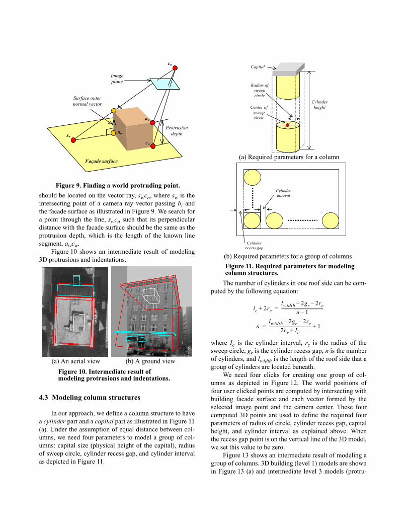
should be located on the vector ray, swcn, where sw is theintersecting point of a camera ray vector passing bi andthe facade surface as illustrated in Figure 9. We search fora point through the line, swcn such that its perpendiculardistance with the facade surface should be the same as theprotrusion depth, which is the length of the known linesegment, awcw.
Figure 10 shows an intermediate result of modeling3D protrusions and indentations.
4.3 Modeling column structures
In our approach, we define a column structure to havea cylinder part and a capital part as illustrated in Figure 11(a). Under the assumption of equal distance between col-umns, we need four parameters to model a group of col-umns: capital size (physical height of the capital), radiusof sweep circle, cylinder recess gap, and cylinder intervalas depicted in Figure 11.
The number of cylinders in one roof side can be com-puted by the following equation:
where Ic is the cylinder interval, rc is the radius of thesweep circle, gr is the cylinder recess gap, n is the numberof cylinders, and lwidth is the length of the roof side that agroup of cylinders are located beneath.
We need four clicks for creating one group of col-umns as depicted in Figure 12. The world positions offour user clicked points are computed by intersecting withbuilding facade surface and each vector formed by theselected image point and the camera center. These fourcomputed 3D points are used to define the required fourparameters of radius of circle, cylinder recess gap, capitalheight, and cylinder interval as explained above. Whenthe recess gap point is on the vertical line of the 3D model,we set this value to be zero.
Figure 13 shows an intermediate result of modeling agroup of columns. 3D building (level 1) models are shownin Figure 13 (a) and intermediate level 3 models (protru-
Figure 9. Finding a world protruding point.
Protrusion depth
Surface outer normal vector
cn
Façade surface
aw
cw
Image plane
sw
bw
uw
(a) An aerial view (b) A ground viewFigure 10. Intermediate result of modeling protrusions and indentations.
Radius of sweep circle
Cylinder height Center of
sweep circle
Capital
Cylinder interval
Cylinder recess gap
(a) Required parameters for a column
(b) Required parameters for a group of columnsFigure 11. Required parameters for modeling column structures.
lc 2rc+lwidth 2gr– 2rc–
n 1–------------------------------------------=
nlwidth 2gr– 2rc–
2cr Ic+------------------------------------------ 1+=
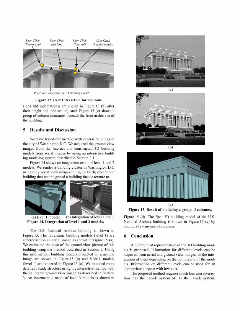
sions and indentations) are shown in Figure 13 (b) aftertheir height and side are adjusted. Figure 13 (c) shows agroup of column structures beneath the front architrave ofthe building.
5 Results and Discussion
We have tested our method with several buildings inthe city of Washington D.C. We acquired the ground viewimages from the Internet and constructed 3D buildingmodels from aerial images by using an interactive build-ing modeling system described in Section 2.1.
Figure 14 shows an integration result of level 1 and 2models. We render a building cluster in Washington D.Cusing only aerial view images in Figure 14 (b) except onebuilding that we integrated a building facade texture to.
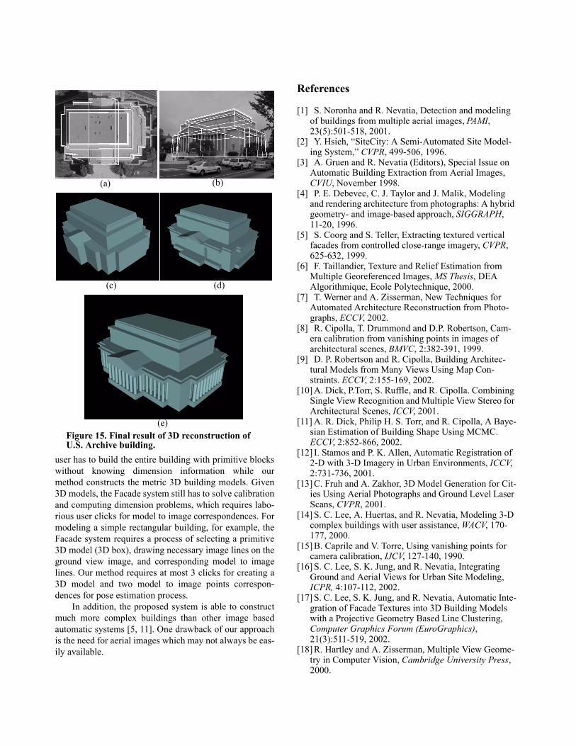
The U.S. National Archive building is shown inFigure 15. The wireframe building models (level 1) aresuperposed on an aerial image as shown in Figure 15 (a).We estimated the pose of the ground view picture of thisbuilding using the method described in Section 2. Usingthis information, building models projected on a groundimage are shown in Figure 15 (b) and VRML models(level 1) are rendered in Figure 15 (c). We modeled moredetailed facade structure using the interactive method withthe calibrated ground view image as described in Section3. An intermediate result of level 3 models is shown in
Figure 15 (d). The final 3D building model of the U.S.National Archive building is shown in Figure 15 (e) byadding a few groups of columns.
6 Conclusion
A hierarchical representation of the 3D building mod-els is proposed. Information for different levels can beacquired from aerial and ground view images, or the inte-gration of them depending on the complexity of the mod-els. Information on different levels can be used for anappropriate purpose with low cost.
The proposed method requires much less user interac-tion than the Facade system [4]. In the Facade system,
Figure 12. User Interaction for columns.
User Click (Radius)
User Click (Recess gap)
User Click (Interval)
User Click (Capital height)
Projected wireframe of 3D building model
(a) level 1 models (b) Integration of level 1 and 2Figure 14. Integration of level 1 and 2 models.
(a)
(b)
(c)Figure 13. Result of modeling a group of columns.
user has to build the entire building with primitive blockswithout knowing dimension information while ourmethod constructs the metric 3D building models. Given3D models, the Facade system still has to solve calibrationand computing dimension problems, which requires labo-rious user clicks for model to image correspondences. Formodeling a simple rectangular building, for example, theFacade system requires a process of selecting a primitive3D model (3D box), drawing necessary image lines on theground view image, and corresponding model to imagelines. Our method requires at most 3 clicks for creating a3D model and two model to image points correspon-dences for pose estimation process.
In addition, the proposed system is able to constructmuch more complex buildings than other image basedautomatic systems [5, 11]. One drawback of our approachis the need for aerial images which may not always be eas-ily available.
References
[1] S. Noronha and R. Nevatia, Detection and modeling of buildings from multiple aerial images, PAMI, 23(5):501-518, 2001.
[2] Y. Hsieh, “SiteCity: A Semi-Automated Site Model-ing System,” CVPR, 499-506, 1996.
[3] A. Gruen and R. Nevatia (Editors), Special Issue on Automatic Building Extraction from Aerial Images, CVIU, November 1998.
[4] P. E. Debevec, C. J. Taylor and J. Malik, Modeling and rendering architecture from photographs: A hybrid geometry- and image-based approach, SIGGRAPH, 11-20, 1996.
[5] S. Coorg and S. Teller, Extracting textured vertical facades from controlled close-range imagery, CVPR, 625-632, 1999.
[6] F. Taillandier, Texture and Relief Estimation from Multiple Georeferenced Images, MS Thesis, DEA Algorithmique, Ecole Polytechnique, 2000.
[7] T. Werner and A. Zisserman, New Techniques for Automated Architecture Reconstruction from Photo-graphs, ECCV, 2002.
[8] R. Cipolla, T. Drummond and D.P. Robertson, Cam-era calibration from vanishing points in images of architectural scenes, BMVC, 2:382-391, 1999.
[9] D. P. Robertson and R. Cipolla, Building Architec-tural Models from Many Views Using Map Con-straints. ECCV, 2:155-169, 2002.
[10] A. Dick, P.Torr, S. Ruffle, and R. Cipolla. Combining Single View Recognition and Multiple View Stereo for Architectural Scenes, ICCV, 2001.
[11] A. R. Dick, Philip H. S. Torr, and R. Cipolla, A Baye-sian Estimation of Building Shape Using MCMC. ECCV, 2:852-866, 2002.
[12] I. Stamos and P. K. Allen, Automatic Registration of 2-D with 3-D Imagery in Urban Environments, ICCV, 2:731-736, 2001.
[13] C. Fruh and A. Zakhor, 3D Model Generation for Cit-ies Using Aerial Photographs and Ground Level Laser Scans, CVPR, 2001.
[14] S. C. Lee, A. Huertas, and R. Nevatia, Modeling 3-D complex buildings with user assistance, WACV, 170-177, 2000.
[15] B. Caprile and V. Torre, Using vanishing points for camera calibration, IJCV, 127-140, 1990.
[16] S. C. Lee, S. K. Jung, and R. Nevatia, Integrating Ground and Aerial Views for Urban Site Modeling, ICPR, 4:107-112, 2002.
[17] S. C. Lee, S. K. Jung, and R. Nevatia, Automatic Inte-gration of Facade Textures into 3D Building Models with a Projective Geometry Based Line Clustering, Computer Graphics Forum (EuroGraphics), 21(3):511-519, 2002.
[18] R. Hartley and A. Zisserman, Multiple View Geome-try in Computer Vision, Cambridge University Press, 2000.
(a) (b)
(c) (d)
(e)Figure 15. Final result of 3D reconstruction of U.S. Archive building.