Embed Size (px)
DESCRIPTION
TEST PATTERN GENERATION USING PODEM ALGORITHM
Citation preview
Path Oriented DEcision Making (PODEM)Muthubalan Varadharajaperumal
Abstract— Automatic-test-pattern generation algorithms generate circuittest patterns, can identify redundant circuit logic and compare various circuitimplementations. Functional test is impractical for larger circuits and E-beamtesting was very expensive. To overcome the above said difficulties structuraltest is used. D algorithm was proposed for pattern generation but this algo-rithm proved to be highly ineffective for faults which needed multiple pathsto be sensitized simultaneously. To overcome this inefficiency PODEM was in-troduced. PODEM expanded the binary decision tree around primary inputvariables only, thus accelerating the algorithm. PODEM algorithm had a sub-routine to check the existence of D-frontier. If not, PODEM backtracks im-mediately, thus speeding up the process. Backtracing is an important methodintroduced by Goel in PODEM.
I. INTRODUCTION
Automatic test-pattern generation (ATPG) is the process of gen-erating patterns to test a circuit. Algorithms for automatic testgeneration focus primarily on ways to produce test patterns forcombinational circuits. These test patterns are applied to the pri-mary input and the effects of these test pattern can be observed inthe primary outputs of the circuit. These patterns, called the testset, must cause all faulty circuits to exhibit different behavior fromgood circuits at the primary outputs. We must be able to apply thetest set economically to all circuits produced. Functional ATPGprograms generate a complete set of test patterns which revealsthe faulty circuit. For a circuit with n input lines, 2n input pat-terns can be generated. If the value of n is in hundreds, a presentATE, operating at 1 GHz, will take approximately 1022 years toapply all the input combination patterns to the circuit-under-test,which is highly impractical. E-beam testing allows observation ofinternal circuit signals by developing a picture of the circuit. Inthis picture, nodes charged to logic 0 and logic 1 are shown in dif-ferent colors. But this method is very expensive and is used forspecialized applications only.
Hence, for larger circuits, the alternative for functional testingis to start with some simplifying assumptions about the possiblefailures. ATPG algorithms inject a fault into a circuit, then acti-vates the fault and causes its effect to propagate to the observableprimary output. The faulty circuit produces an output which isdifferent from the fault free circuit. Three of the best known algo-rithms for ATPG are the D algorithm, PODEM and FAN. The Dalgorithm is inefficient when certain faults in a combinational cir-cuit require multiple paths to be sensitized simultaneously for theirdetection. In the worst case, D algorithm requires the sensitizationof each possible combination of the set of gates on a path from thefault site and this can include a large number unnecessary com-binations of sensitized gates [1] [2]. To improve this inefficiencyof D algorithm, PODEM (Path Oriented DEcision Making) wasproposed by Goel.
II. DECISION TREE
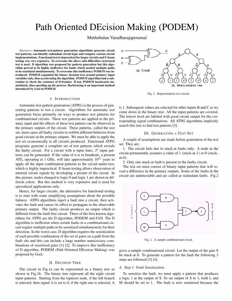
The circuit in Fig.1a can be represented as a binary tree asshown in Fig.1b. The binary tree represent all the eight circuitinput patterns. Starting from the topmost node, if the left branchis selected, then signal A is set to 0, if the right one is selected, A
Fig. 1. Representation of a circuit.
is 1. Subsequent values are selected for other inputs B and C as wecome down in the binary tree. All the input patterns are covered.The lowest level are labeled with good circuit output for the cor-responding signal combinations. All ATPG algorithms implicitlysearch this tree to find test patterns [3].
III. GENERATING A TEST SET
A couple of assumptions are made before generation of the testset. They are:
1. The circuit fails due to stuck-at faults only. A node in thecircuit permanently assumes a value of 1 (stuck-at-1) or 0 (stuck-at-0).
2. Only one stuck-at fault is present in the faulty circuit.The test set must consist of binary input patterns that will re-
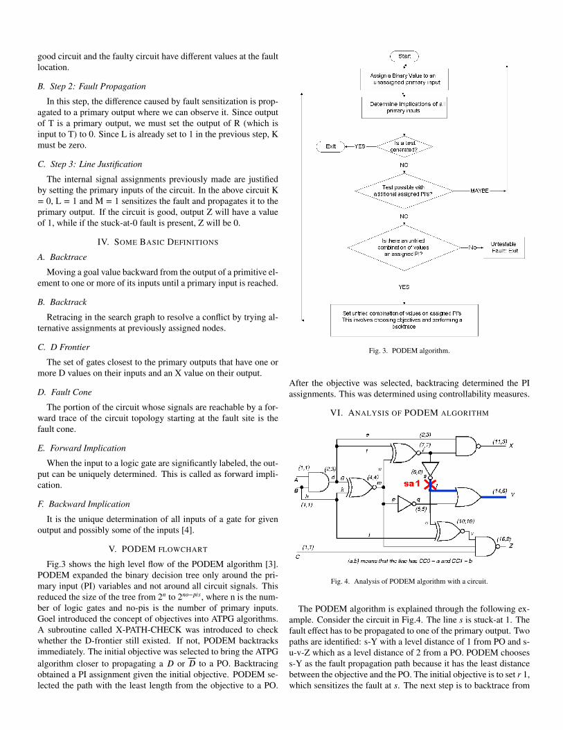
veal a difference in the primary outputs. Some of the faults in thecircuit are undetectable and are called as redundant faults. Fig.2
Fig. 2. A sample combinational circuit.
gives a sample combinational circuit. Let the output of the gate Sbe stuck-at 0. To generate a pattern for the fault the following 3steps are followed [3] [4].
A. Step 1: Fault Sensitization
To sensitize the fault, we must apply a pattern that producesa logic 1 at the output of S. To set output of S to 1, both L andM should be set to 1. The fault is now sensitized because the
good circuit and the faulty circuit have different values at the faultlocation.
B. Step 2: Fault Propagation
In this step, the difference caused by fault sensitization is prop-agated to a primary output where we can observe it. Since outputof T is a primary output, we must set the output of R (which isinput to T) to 0. Since L is already set to 1 in the previous step, Kmust be zero.
C. Step 3: Line Justification
The internal signal assignments previously made are justifiedby setting the primary inputs of the circuit. In the above circuit K= 0, L = 1 and M = 1 sensitizes the fault and propagates it to theprimary output. If the circuit is good, output Z will have a valueof 1, while if the stuck-at-0 fault is present, Z will be 0.
IV. SOME BASIC DEFINITIONS
A. Backtrace
Moving a goal value backward from the output of a primitive el-ement to one or more of its inputs until a primary input is reached.
B. Backtrack
Retracing in the search graph to resolve a conflict by trying al-ternative assignments at previously assigned nodes.
C. D Frontier
The set of gates closest to the primary outputs that have one ormore D values on their inputs and an X value on their output.
D. Fault Cone
The portion of the circuit whose signals are reachable by a for-ward trace of the circuit topology starting at the fault site is thefault cone.
E. Forward Implication
When the input to a logic gate are significantly labeled, the out-put can be uniquely determined. This is called as forward impli-cation.
F. Backward Implication
It is the unique determination of all inputs of a gate for givenoutput and possibly some of the inputs [4].
V. PODEM FLOWCHART
Fig.3 shows the high level flow of the PODEM algorithm [3].PODEM expanded the binary decision tree only around the pri-mary input (PI) variables and not around all circuit signals. Thisreduced the size of the tree from 2n to 2no−pis, where n is the num-ber of logic gates and no-pis is the number of primary inputs.Goel introduced the concept of objectives into ATPG algorithms.A subroutine called X-PATH-CHECK was introduced to checkwhether the D-frontier still existed. If not, PODEM backtracksimmediately. The initial objective was selected to bring the ATPGalgorithm closer to propagating a D or D to a PO. Backtracingobtained a PI assignment given the initial objective. PODEM se-lected the path with the least length from the objective to a PO.
Fig. 3. PODEM algorithm.
After the objective was selected, backtracing determined the PIassignments. This was determined using controllability measures.
VI. ANALYSIS OF PODEM ALGORITHM
Fig. 4. Analysis of PODEM algorithm with a circuit.
The PODEM algorithm is explained through the following ex-ample. Consider the circuit in Fig.4. The line s is stuck-at 1. Thefault effect has to be propagated to one of the primary output. Twopaths are identified: s-Y with a level distance of 1 from PO and s-u-v-Z which as a level distance of 2 from a PO. PODEM choosess-Y as the fault propagation path because it has the least distancebetween the objective and the PO. The initial objective is to set r 1,which sensitizes the fault at s. The next step is to backtrace from
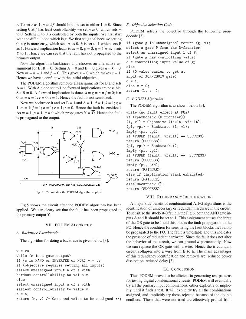
r. To set r as 1, n and f should both be set to either 1 or 0. Sincesetting 0 at f has least controllability we set n as 0, which sets mto 0. Setting m to 0 is controlled by both the inputs. We first startwith the difficult one which is g. We first set g to 0 because setting0 in g is more easy, which sets A as 0. k is set to 1 which sets Bas 1. Forward implication leads to m = 0, p = 0, q = 1 which setsY to 1. Hence we can see that the fault has not propagated to theprimary output.
Now the algorithm backtraces and chooses an alternative as-signment for B, B = 0. Setting A = 0 and B = 0 gives g = k = 0.Now m = n = 1 and f = 0. This gives r = 0 which makes s = 1.Hence we have a conflict with the initial objective.
The PODEM algorithm removes all assignments for B and setsA = 1. With A alone set to 1 no forward implications are possible.Set B = 0. A forward implication is done. d = g = e = f = 0; k =0; m = n = 1; r = 0; s = 1. Hence the fault is not sensitized.
Now we backtrace it and set B = 1 and A = 1. d = 1; k = 1; g =1; m = 1; f = 1; n = 1; r = 1; s = 0. Hence the fault is sensitized.As m = 1, p = 1; q = 0 which propagates Y = D. Hence the faultis propagated to the output.
Fig. 5. Circuit after the PODEM algorithm applied.
Fig.5 shows the circuit after the PODEM algorithm has beenapplied. We can cleary see that the fault has been propagated tothe primary output Y.
VII. PODEM ALGORITHM
A. Backtrace Pseudocode
The algorithm for doing a backtrace is given below [3].
v = vs;
while (s is a gate output)
if (s is NAND or INVERTER or NOR) v = v;
if (objective requires setting all inputs)
select unassigned input a of s with
hardest controllability to value v;
else
select unassigned input a of s with
easiest controllability to value v;
s = a;
return (s, v) /* Gate and value to be assigned */;
B. Objective Selection Code
PODEM selects the objective through the following pseu-docode [3].
if (gate g is unassigned) return (g, v);
select a gate P from the D-frontier;
select an unassigned input l of P;
if (gate g has controlling value)
c = controlling input value of g;
else
if (0 value easier to get at
input of XOR/EQUIV gate)
c = 1;
else c = 0;
return (l, c );
C. PODEM Algorithm
The PODEM algorithm is as shown below [3].
while (no fault effect at POs)
if (xpathcheck (D-frontier))
(l, vl) = Objective (fault, vfault);
(pi, vpi) = Backtrace (l, vl);
Imply (pi, vpi);
if (PODEM (fault, vfault) == SUCCESS)
return (SUCCESS);
(pi, vpi) = Backtrack ();
Imply (pi, vpi);
if (PODEM (fault, vfault) == SUCCESS)
return (SUCCESS);
Imply (pi, ŁX�);
return (FAILURE);
else if (implication stack exhausted)
return (FAILURE);
else Backtrack ();
return (SUCCESS);
VIII. REDUNDANCY IDENTIFICATION
A major side benefit of combinational ATPG algorithms is theidentification of unnecessary or redundant hardware in the circuit.To sensitize the stuck-at-0 fault in the Fig.6, both the AND gate in-puts A and B should be set to 1. This assignment causes the inputof the OR gate to be 1 and this blocks the fault propagation to thePO. Hence the condition for sensitizing the fault blocks the fault tobe propagated to the PO. The fault is untestable and this indicatesthe presence of redundant hardware. Since the fault does not alterthe behavior of the circuit, we can ground d permanently. Nowwe can replace the OR gate with a wire. Hence the irredundantcircuit collapses into a wire from B to E. The main advantagesof this redundancy identification and removal are: reduced powerdissipation, reduced delay [3].
IX. CONCLUSION
Thus PODEM proved to be efficient in generating test patternsfor testing digital combinational circuits. PODEM will eventuallytry all the primary input combinations, either explicitly or implic-itly, until it finds a test. It will explicitly try all the combinationsassigned, and implicitly try those rejected because of the doubleconflicts. Those that were not tried are effectively pruned from
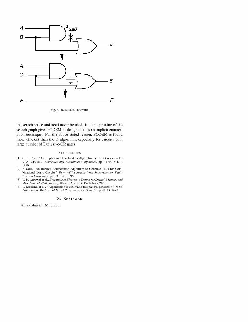
Fig. 6. Redundant hardware.
the search space and need never be tried. It is this pruning of thesearch graph gives PODEM its designation as an implicit enumer-ation technique. For the above stated reason, PODEM is foundmore efficient than the D algorithm, especially for circuits withlarge number of Exclusive-OR gates.
REFERENCES
[1] C. H. Chen, "An Implication Acceleration Algorithm in Test Generation forVLSI Circuits," Aerospace and Electronics Conference, pp. 43-46, Vol. 1,1990.
[2] P. Goel, "An Implicit Enumeration Algorithm to Generate Tests for Com-binational Logic Circuits," Twenty-Fifth International Symposium on Fault-Tolerant Computing, pp. 337-343, 1995.
[3] V. D. Agrawal et al., Essentials of Electronic Testing for Digital, Memory andMixed-Signal VLSI circuits,, Kluwer Academic Publishers, 2001.
[4] T. Kirkland et al., "Algorithms for automatic test-pattern generation," IEEETransactions Design and Test of Computers, vol. 5, no. 3, pp. 43-55, 1988.
X. REVIEWER
Anandshankar Mudlapur


![PGEN: Novel Approach Sequential Circuit Generationdownloads.hindawi.com/archive/1996/068463.pdf · The PODEM algorithm [10] used for combina-tional circuit testing is transplanted](https://img.pdfslide.us/doc/110x75/5e889fefbf28cd219b763703/pgen-novel-approach-sequential-circuit-the-podem-algorithm-10-used-for-combina-tional.jpg)