Embed Size (px)
Citation preview
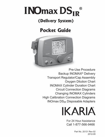
For 24 Hour AssistanceCall 1-877-566-9466
Part No. 20131 Rev-022012-09
Pocket Guide
(Delivery System)
Pre-Use ProcedureBackup INOMAX® Delivery
Transport Regulator/Cap AssemblyOxygen Dilution Chart
INOMAX Cylinder Duration ChartCircuit Connection DiagramsChanging INOMAX Cylinders
High Calibration Connection DiagramsINOmax DSIR Disposable Adapters
2Part No. 20131 Rev-022012-09
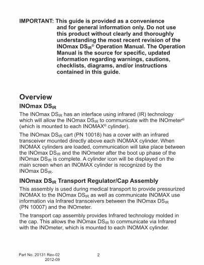
IMPORTANT: This guide is provided as a convenience and for general information only. Do not use this product without clearly and thoroughly understanding the most recent revision of the INOmax DSIR® Operation Manual. The Operation Manual is the source for specific, updated information regarding warnings, cautions, checklists, diagrams, and/or instructions contained in this guide.
OverviewINOmax DSIRThe INOmax DSIR has an interface using infrared (IR) technology which will allow the INOmax DSIR to communicate with the INOmeter® (which is mounted to each INOMAX® cylinder).The INOmax DSIR cart (PN 10018) has a cover with an infrared transceiver mounted directly above each INOMAX cylinder. When INOMAX cylinders are loaded, communication will take place between the INOmax DSIR and the INOmeter after the boot up phase of the INOmax DSIR is complete. A cylinder icon will be displayed on the main screen when an INOMAX cylinder is recognized by the INOmax DSIR.
INOmax DSIR Transport Regulator/Cap AssemblyThis assembly is used during medical transport to provide pressurized INOMAX to the INOmax DSIR as well as communicate INOMAX use information via Infrared transceivers between the INOmax DSIR (PN 10007) and the INOmeter.The transport cap assembly provides Infrared technology molded in the cap. This allows the INOmax DSIR to communicate via Infrared with the INOmeter, which is mounted to each INOMAX cylinder.
3 Part No. 20131 Rev-022012-09
DefinitionsINOmeter - The factory installed INOmeter is designed for use with INOMAX cylinders only. This time-metric device records the amount of time the cylinder valve is opened.iButton – Raised silver data port on the side of the INOmeter.
Symbols
Infrared Input/Output
©2012 Ikaria, Inc.INOMAX®, INOmax DSIR®, INOblender®, INOcal®, INOmeter® and INOvent® are registered trademarks of INO Therapeutics LLC.
4Part No. 20131 Rev-022012-09
Contents
Pre-Use Checkout .....................................................................................5Backup INOMAX Delivery .......................................................................12Transport Regulator/Cap Assembly .........................................................14Oxygen Dilution Chart .............................................................................18INOMAX Cylinder 88-size Duration Chart ...............................................19INOMAX Cylinder D-size Duration Chart.................................................20Connection to Various Breathing Systems ..............................................22 A-Plus Medical Babi-Plus Bubble CPAP ........................................... 23 Bagging Systems While Using the Injector Module ...........................24 Bunnell Life Pulse High Frequency Ventilator Circuit ........................28 Connecting INOmax DSIR Sample Tee to the Bunnell Life Pulse Circuit ..................................................................................30 Connecting INOmax DSIR Injector Module to the Bunnell Life Pulse Circuit ..................................................................................30 Circle Anesthesia System ..................................................................31 Fisher & Paykel Healthcare Bubble CPAP.........................................32 Fisher & Paykel Healthcare Infant Circuit Nasal Cannula .................33 Fisher&PaykelHealthcareOptiflowBreathingCircuit ......................34 Hamilton Arabella Nasal CPAP ..........................................................35 ICU Ventilator Circuit .........................................................................36 Sensormedics 3100A/B High Frequency Oscillatory Ventilator with a Filtered Circuit ....................................................................37 Sensormedics 3100A/B High Frequency Oscillatory Ventilator with a Rigid or Flexible Circuit .......................................................38 Spontaneous Breathing Patient on a Mask Circuit ............................39 Spontaneous Breathing Patient on a Nasal Cannula ........................40 TeleflexMedicalComfortFloHumidificationSystem .........................41 Transport Ventilator Circuit ................................................................42 Vapotherm 2000i ................................................................................46 Vapotherm Precision Flow .................................................................47 Viasys Infant Flow CPAP System; Cardinal Airlife nCPAP System ........... 48 Viasys Infant Flow SiPAP ...................................................................49INOblender Circuit Connection ................................................................50 Fisher & Paykel Healthcare Neopuff Resuscitator .............................51Changing INOMAX Cylinders ..................................................................52High Calibration Connection Diagrams ...................................................56INOmax DSIR Disposable Adapters .........................................................58
5 Part No. 20131 Rev-022012-09
Pre-Use Checkout Outline
A. Initial Connections
B. High Pressure Leak Test
C. Low Range Calibration
D. Purge and Alarm Verification
E. Backup INOMAX Delivery Test
F. INOmax DSIR Performance Test
G. INOblender Test
Pre-Use Checkout
6Part No. 20131 Rev-022012-09
A. Initial Connections
1. Check white plastic tip.
2. Connect high pressure regulator.
Pre-Use Checkout
7 Part No. 20131 Rev-022012-09
Pre-Use Checkout
3. Connect the INOMAX regulator hose to one of the INOMAX inlets
4. Connect the INOblender inlet hose to the INOmax DSIR blender outlet
5. Connect the infrared cable to the back of the INOmax DSIR
6. Connect the oxygen hose to the INOblender oxygen inlet7. Ensure the water separator cartridge/water trap bottle/
sample line and injector module are all in place8. Turn INOmax DSIR ON, verify
speaker function.
7
7
7
6
8
3 4 5
8Part No. 20131 Rev-022012-09
B. Perform High Pressure Leak Test
Wait 30 seconds and ensure no pressure drop.
C. Perform Low Range Calibration
(Open/Close INOMAX cylinder valve)
(second menu level)
Pre-Use Checkout
Note: Once the calibration is completed (bars turn green and single tone sounds) press the menu button twice to return to the main screen.
Note: Make sure INOmax DSIR backup and INOblender are OFF.
9 Part No. 20131 Rev-022012-09
D. Perform Purge and Alarm Verification
Pre-Use Checkout
1. O2 Flowmeter (Connected to wall/tank)2. O2 Tubing3. 15M x 4.5mm Adapter4. 22M / 15F x 22M / 15F Adapter5. Injector Module
3
110 9 8
2 54 76
6. 300mm of 22mm Hose7. Gas Sample Tee8. Patient Gas Sample Line withNafion9. NO/N2 Injector Tube10. Injector Module Electrical Cable
(Assemble connectors and tubing as shown)
1. Ensure cylinder valve is closed.2. Set O2flowmeterto10L/min.3. Purge INOmax DSIR. a. Set INOMAX dose to 40 ppm b. “Cylinder Valve Closed” alarm will occur c. Cylinder gauge pressure should drop to 0 psig d. Purge is complete when “Low NO/N2 Pressure” alarm activates4. Open cylinder valve.5. Turn INOMAX dose to zero (note: The “Set Dose is Zero, Close
Cylinder Valve” indicator will appear).
10Part No. 20131 Rev-022012-09
F. Complete INOmax DSIR Performance Test
1. Ensure oxygen flow of 10 L/min.
2. Set INOMAX dose to 40 ppm and allow values to stabilize.
3. Verify values (see table).
4. Turn the INOMAX dose to zero.
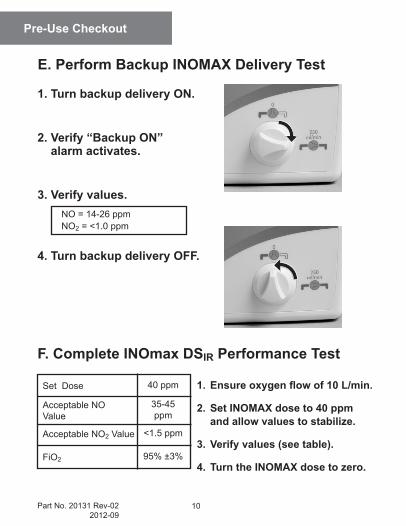
NO = 14-26 ppmNO2 = <1.0 ppm
Set Dose
Acceptable NOValue
Acceptable NO2 Value
FiO2
40 ppm
35-45 ppm
<1.5 ppm
95% ±3%
1. Turn backup delivery ON.
2. Verify “Backup ON” alarm activates.
3. Verify values.
4. Turn backup delivery OFF.
E. Perform Backup INOMAX Delivery Test
Pre-Use Checkout
11 Part No. 20131 Rev-022012-09
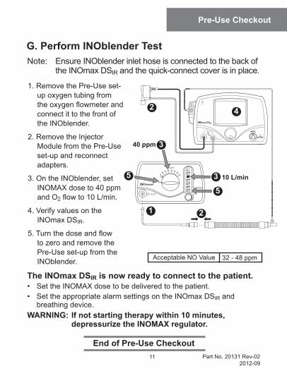
Acceptable NO Value 32 - 48 ppm
G. Perform INOblender Test
End of Pre-Use Checkout
Pre-Use Checkout
Note: Ensure INOblender inlet hose is connected to the back of the INOmax DSIR and the quick-connect cover is in place.
1. Remove the Pre-Use set-up oxygen tubing from theoxygenflowmeterandconnect it to the front of the INOblender.
2. Remove the Injector Module from the Pre-Use set-up and reconnect adapters.
3. On the INOblender, set INOMAX dose to 40 ppm and O2flowto10L/min.
4. Verify values on the INOmax DSIR.
5.Turnthedoseandflowto zero and remove the Pre-Use set-up from the INOblender.
The INOmax DSIR is now ready to connect to the patient.• SettheINOMAXdosetobedeliveredtothepatient.• SettheappropriatealarmsettingsontheINOmaxDSIR and
breathing device.WARNING: If not starting therapy within 10 minutes,
depressurize the INOMAX regulator.
10 L/min
4
1
2
3
5
5
2
3
40 ppm
12Part No. 20131 Rev-022012-09
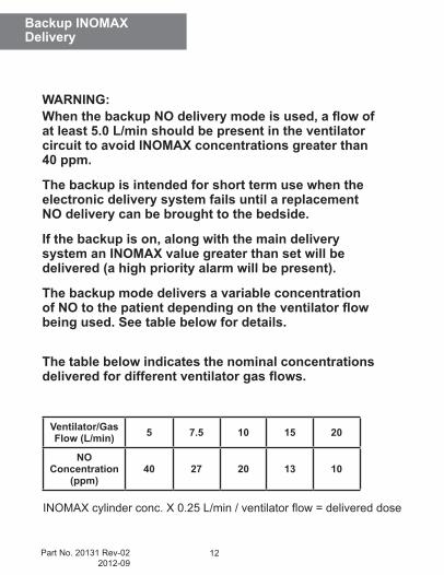
WARNING:When the backup NO delivery mode is used, a flow of at least 5.0 L/min should be present in the ventilator circuit to avoid INOMAX concentrations greater than 40 ppm.
The backup is intended for short term use when the electronic delivery system fails until a replacement NO delivery can be brought to the bedside.
If the backup is on, along with the main delivery system an INOMAX value greater than set will be delivered (a high priority alarm will be present).
The backup mode delivers a variable concentration of NO to the patient depending on the ventilator flow being used. See table below for details.
The table below indicates the nominal concentrations delivered for different ventilator gas flows.
Backup INOMAX Delivery
Ventilator/Gas Flow (L/min) 5 7.5 10 15 20
NO Concentration
(ppm)40 27 20 13 10
INOMAXcylinderconc.X0.25L/min/ventilatorflow=delivereddose
13 Part No. 20131 Rev-022012-09
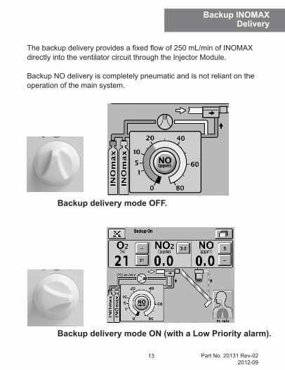
Thebackupdeliveryprovidesafixedflowof250mL/minofINOMAXdirectly into the ventilator circuit through the Injector Module.
Backup NO delivery is completely pneumatic and is not reliant on the operation of the main system.
Backup delivery mode OFF.
Backup delivery mode ON (with a Low Priority alarm).
Backup INOMAX Delivery
14Part No. 20131 Rev-022012-09
Transport Regulator/ Cap Assembly
Figure 1 Figure 2
Transport Regulator/Cap Assembly
WARNING:• A new INOMAX cylinder and regulator must be purged
before use to ensure the patient does not receive greater than 1.0 ppm of NO2.
• Loss of communication between the INOmax DSIR and the INOMAX cylinder for more than one hour will result in interruption of INOMAX delivery.
Caution: When using the Transport Regulator/Cap Assembly (PN 10022) ensure the cap is in place on the cylinder and the infrared cable is connected to the infrared connector port on the back of the INOmax DSIR.
Note: Check the INOMAX cylinder for the correct product identity labels, cylinder concentration and expiration date. Ensure the INOMAX gas cylinder has more than 200 psig.
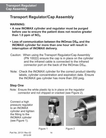
Step OneNote: Ensure the white plastic tip is in place on the regulator
connector and not chipped or cracked (see Figure 2).
Connect a high pressure regulator to an INOMAX cylinder and tighten thefittingtotheINOMAX cylinder (see Figure 1).
15 Part No. 20131 Rev-022012-09
Transport Regulator/ Cap Assembly
Figure 3
Figure 4
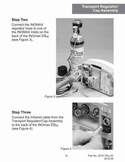
Step TwoConnect the INOMAX regulator hose to one of the INOMAX inlets on the back of the INOmax DSIR (see Figure 3).
Step ThreeConnect the Infrared cable from the Transport Regulator/Cap Assembly to the back of the INOmax DSIR (see Figure 4).
16Part No. 20131 Rev-022012-09
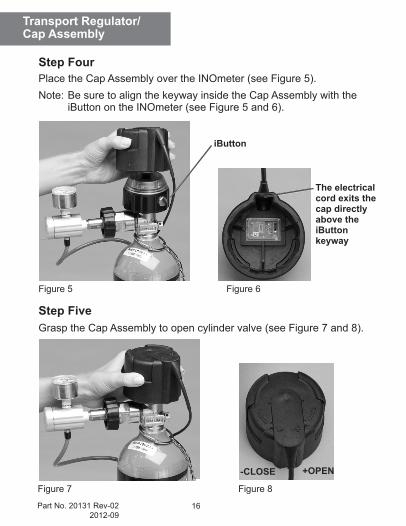
iButton
The electrical cord exits the cap directly above the iButton keyway
-CLOSE +OPEN
Figure 5 Figure 6
Figure 7 Figure 8
Transport Regulator/ Cap Assembly
Step FourPlace the Cap Assembly over the INOmeter (see Figure 5).Note: Be sure to align the keyway inside the Cap Assembly with the
iButton on the INOmeter (see Figure 5 and 6).
Step FiveGrasp the Cap Assembly to open cylinder valve (see Figure 7 and 8).
17 Part No. 20131 Rev-022012-09
Figure 9
Transport Regulator/ Cap Assembly
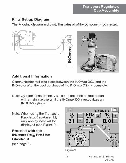
Final Set-up DiagramThe following diagram and photo illustrates all of the components connected.
Additional InformationCommunication will take place between the INOmax DSIR and the INOmeter after the boot up phase of the INOmax DSIR is complete.
Note: Cylinder icons are not visible and the dose control button will remain inactive until the INOmax DSIR recognizes an INOMAX cylinder.
Note: When using the Transport Regulator/Cap Assembly only one cylinder will be displayed (see Figure 9).
Proceed with the INOmax DSIR Pre-Use Checkout(see page 6)
18Part No. 20131 Rev-022012-09
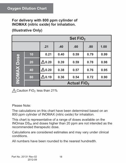
Oxygen Dilution Chart
For delivery with 800 ppm cylinder of INOMAX (nitric oxide) for inhalation.(Illustrative Only)
Caution FiO2 less than 21%
Please Note:The calculations on this chart have been determined based on an 800 ppm cylinder of INOMAX (nitric oxide) for inhalation.This chart is representative of a range of doses available on the INOmax DSIR and doses higher than 20 ppm are not intended as the recommended therapeutic dose.Calculations are considered estimates and may vary under clinical conditions. All numbers have been rounded to the nearest hundredth.
0.21
0.20
0.20
0.19
0.40
0.39
0.38
0.36
0.59
0.59
0.57
0.54
0.79
0.78
0.76
0.72
.21 .40 .60 .80
Set FiO2
10
20
40
80
1.00
0.99
0.98
0.95
0.90
Actual FiO2
!
!
!
INO
MA
X D
ose
19 Part No. 20131 Rev-022012-09
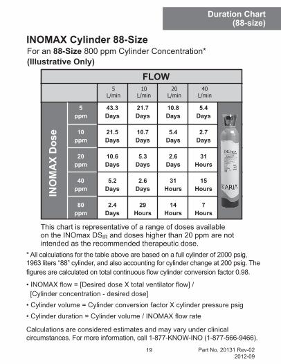
For an 88-Size 800 ppm Cylinder Concentration*(Illustrative Only)
* All calculations for the table above are based on a full cylinder of 2000 psig, 1963 liters “88” cylinder, and also accounting for cylinder change at 200 psig. The figuresarecalculatedontotalcontinuousflowcylinderconversionfactor0.98.
•INOMAXflow=[DesireddoseXtotalventilatorflow]/ [Cylinderconcentration-desireddose]•Cylindervolume=CylinderconversionfactorXcylinderpressurepsig•Cylinderduration=Cylindervolume/INOMAXflowrate
Calculations are considered estimates and may vary under clinical circumstances. For more information, call 1-877-KNOW-INO (1-877-566-9466).
INOMAX Cylinder 88-Size
Duration Chart(88-size)
This chart is representative of a range of doses available on the INOmax DSIR and doses higher than 20 ppm are not intended as the recommended therapeutic dose.
INO
MA
X D
ose
5ppm
10ppm
20ppm
40ppm
80ppm
43.3Days
21.5Days
10.6Days
5.2Days
2.4Days
21.7Days
10.7Days
5.3Days
2.6Days
29Hours
10.8Days
5.4Days
2.6Days
31Hours
14Hours
5.4Days
2.7Days
31Hours
15Hours
7Hours
FLOW5
L/min10
L/min20
L/min40
L/min
20Part No. 20131 Rev-022012-09
Duration Chart(D-size)
7.8Days
3.9Days
45Hours
22Hours
10Hours
3.9Days
46Hours
22Hours
11Hours
5Hours
46Hours
23Hours
11Hours
5Hours
2Hours
23Hours
11Hours
5Hours
2Hours
1Hour
5L/min
10L/min
20L/min
40L/min
FLOW
5ppm
10ppm
20ppm
40ppm
80ppm
INO
MA
X D
ose
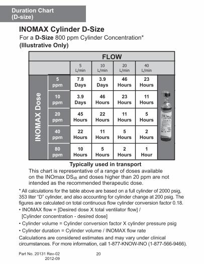
* All calculations for the table above are based on a full cylinder of 2000 psig, 353 liter “D” cylinder, and also accounting for cylinder change at 200 psig. The figuresarecalculatedontotalcontinuousflowcylinderconversionfactor0.18.•INOMAXflow=[DesireddoseXtotalventilatorflow]/ [Cylinderconcentration-desireddose]•Cylindervolume=CylinderconversionfactorXcylinderpressurepsig•Cylinderduration=Cylindervolume/INOMAXflowrateCalculations are considered estimates and may vary under clinical circumstances. For more information, call 1-877-KNOW-INO (1-877-566-9466).
This chart is representative of a range of doses available on the INOmax DSIR and doses higher than 20 ppm are not intended as the recommended therapeutic dose.
For a D-Size 800 ppm Cylinder Concentration*(Illustrative Only)
INOMAX Cylinder D-Size
Typically used in transport

21 Part No. 20131 Rev-022012-09
Duration Chart(D-size)
(Intentionally left blank)
22Part No. 20131 Rev-022012-09
Proper use of these products depends on careful reading and understanding of labeling and instructions. Please refer to the INOmax DSIR and INOblender operation manuals for guidance. Also refertothespecificbreathingdeviceoperationmanualorinstructionsfor use.
INOmax DSIR Warnings: • INOmax DSIR subtracts gas from the breathing circuit via the
gas sampling system at 230 mL per minute; this can affect the sensitivity of a flow triggered synchronized breath mode of some ventilators. The trigger sensitivity of the ventilator should be checked after connecting the INOmax DSIR to the breathing circuit.
• Patient disconnect and high-pressure alarms are required for the ventilator.
INOmax DSIR Cautions:• InserttheInjectorModuleonthedrysideofthebreathingcircuitpriortothehumidifier(thiswillensurecorrectflowmeasurement).
• Avoidmedicationsinterferingwiththegasmonitoringsystem;administer any aerosolized medications distal to the sampling tee.
Circuit ConnectionDiagrams
23 Part No. 20131 Rev-022012-09
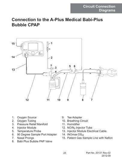
Connection to the A-Plus Medical Babi-Plus Bubble CPAP
1. Oxygen Source2. Oxygen Tubing3. Pressure Relief Manifold4. Injector Module5. Temperature Probe6. 90 Degree Sample Port Adapter7. Nasal Prongs8. Babi Plus Bubble PAP Valve
9. Tee Adapter10. Breathing Circuit11. Humidifier12. NO/N2 Injector Tube13. Injector Module Electrical Cable14. INOmax DSIR15. PatientGasSampleLinewithNafion
9 811 710
14
34
6
2
5
12
13
115
Circuit ConnectionDiagrams
24Part No. 20131 Rev-022012-09
Circuit ConnectionDiagrams
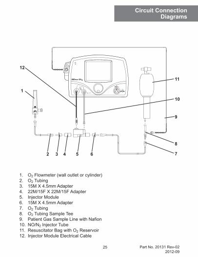
Connection to Bagging Systems While Using the Injector Module
WARNING: To minimize the delivered concentration of NO2, the following steps should be taken for use with the manual resuscitator bags:• Use the smallest bag adequate to deliver the
desired tidal volume.• Inspiratory tubing lengths greater than 72
inches should not be used.• Use the highest fresh gas flow rated (up to 15
L/min) that is practical.• Use the lowest practical inspired oxygen
concentration.• After starting fresh gas flow, squeeze the bag
several times to empty residual gas in the bag prior to using the system to ventilate a patient.
25 Part No. 20131 Rev-022012-09
Circuit ConnectionDiagrams
1
52 643
10
12
11
9
8
7
1. O2 Flowmeter (wall outlet or cylinder)2. O2 Tubing3. 15M X 4.5mm Adapter4. 22M/15F X 22M/15F Adapter5. Injector Module6. 15M X 4.5mm Adapter7. O2 Tubing8. O2 Tubing Sample Tee9. PatientGasSampleLinewithNafion10. NO/N2 Injector Tube11. Resuscitator Bag with O2 Reservoir12. Injector Module Electrical Cable
26Part No. 20131 Rev-022012-09
Circuit ConnectionDiagrams
WARNING:• The hyperinflation bag will, under some conditions, contain NO2 in excess of
1 ppm. Use of large tidal volume breaths may expose the patients to the NO2 present in the bag, for part of the breath. In general, if the inspiratory flow rate induced by the manual ventilation does not exceed the fresh gas flow rate, the patient should not be exposed to the concentrations of NO2 present in the hyperinflation bag.
• Adult and infant hyperinflation bags generate more NO2 when used at lower minute ventilation. If use of the bag is interrupted (for example to adjust the tracheal tube), before resuming ventilation of the patient, the user should squeeze the bag several times to empty residual gas from the bag.
• Because of the potential for inhalation of excessive concentrations of NO2, and the difficulty in monitoring the peak inhaled NO2 concentrations, ventilation with a hyperinflation bag or self inflating bag is intended only for short term use.
• The monitoring system within the INOmax DSIR will not detect generation of NO2 within the hyperinflation bag or self-inflating bag devices and the alarms for excessive NO2 cannot warn of NO2 produced within the manual bag system.
• To minimize the delivered concentration of NO2, the following steps should be taken for use with the manual resuscitator bags:
- Concentrations greater than 20 ppm NO should not be used because of excessive NO2 generation.
- Use the smallest bag adequate to deliver the desired tidal volume. - Inspiratory tubing lengths greater than 72 inches should not be used. - Use the highest fresh gas flow rate (up to 15 L/min) that is practical. - Use the lowest practical inspired oxygen concentration. - After starting fresh gas flow, squeeze the bag several times to empty
residual gas in the bag prior to using the system to ventilate a patient.
27 Part No. 20131 Rev-022012-09
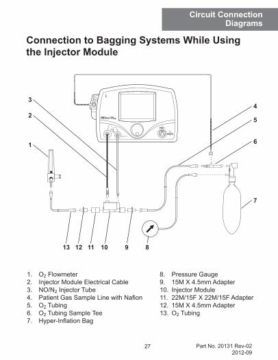
Circuit ConnectionDiagrams
1. O2 Flowmeter 2. Injector Module Electrical Cable3. NO/N2 Injector Tube4. PatientGasSampleLinewithNafion5. O2 Tubing6. O2 Tubing Sample Tee7. Hyper-InflationBag
8. Pressure Gauge9. 15M X 4.5mm Adapter10. Injector Module11. 22M/15F X 22M/15F Adapter12. 15M X 4.5mm Adapter13. O2 Tubing
1011 9 81213
7
6
42
3
1
5
Connection to Bagging Systems While Using the Injector Module
28Part No. 20131 Rev-022012-09
Circuit ConnectionDiagrams
Connection to a Bunnell Life Pulse High Frequency Ventilator Circuit
WARNING:• The INOmax DSIR backup mode (250 mL/min.) should not
be used with the Bunnell Life Pulse as ventilator flow rates are normally below the recommended ventilator flows.
• Place the Life Pulse in Standby prior to suctioning the patient to avoid NO delivery transiently exceeding the set dose by up to 30 ppm. Press ENTER to reestablish ventilation as soon as the catheter is removed from the airway. This will limit the extent of over delivery above the NO set dose.
Caution:• Ifthesetdoseisbelow5ppmandtheServopressureis2.0psig.orless,thiswillresultinflowratesoutsideofthespecificationoftheInjectorModuleandfluctuatingNOvaluesmayresult.
• Aone-wayvalveshouldbeplacedbetweentheinjectormoduleandthehumidifierchambertopreventwaterfrombackingupintothe injector module if the Life Pulse is either put into Standby or cycled OFF.
• Therearehigherpressuresinthebreathingcircuitthannormal;use only parts provided in disposable package #50046 and tightly secure all connections.
29 Part No. 20131 Rev-022012-09
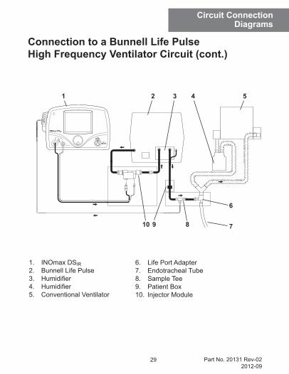
Circuit ConnectionDiagrams
1. INOmax DSIR2. Bunnell Life Pulse3. Humidifier4. Humidifier5. Conventional Ventilator
1 2 3 4 5
6
810 79
6. Life Port Adapter7. Endotracheal Tube8. Sample Tee9. Patient Box10. Injector Module
Connection to a Bunnell Life Pulse High Frequency Ventilator Circuit (cont.)
30Part No. 20131 Rev-022012-09
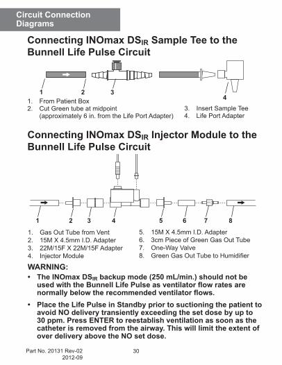
Connecting INOmax DSIR Injector Module to the Bunnell Life Pulse Circuit
Connecting INOmax DSIR Sample Tee to the Bunnell Life Pulse Circuit
1. Gas Out Tube from Vent2. 15M X 4.5mm I.D. Adapter3. 22M/15F X 22M/15F Adapter4. Injector Module
1 2 34
5. 15M X 4.5mm I.D. Adapter6. 3cm Piece of Green Gas Out Tube7. One-Way Valve8. GreenGasOutTubetoHumidifier
1. From Patient Box2. Cut Green tube at midpoint (approximately 6 in. from the Life Port Adapter)
1 2 3 4 5 6 7 8
3. Insert Sample Tee4. Life Port Adapter
WARNING:• The INOmax DSIR backup mode (250 mL/min.) should not be
used with the Bunnell Life Pulse as ventilator flow rates are normally below the recommended ventilator flows.
• Place the Life Pulse in Standby prior to suctioning the patient to avoid NO delivery transiently exceeding the set dose by up to 30 ppm. Press ENTER to reestablish ventilation as soon as the catheter is removed from the airway. This will limit the extent of over delivery above the NO set dose.
Circuit ConnectionDiagrams
31 Part No. 20131 Rev-022012-09
Circuit ConnectionDiagrams
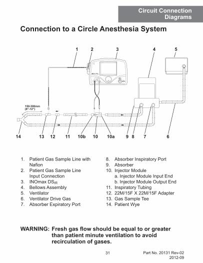
Connection to a Circle Anesthesia System
1. Patient Gas Sample Line with Nafion2. Patient Gas Sample Line Input Connection3. INOmax DSIR4. Bellows Assembly5. Ventilator6. Ventilator Drive Gas7. Absorber Expiratory Port
8. Absorber Inspiratory Port9. Absorber10. Injector Module a. Injector Module Input End b. Injector Module Output End11. Inspiratory Tubing12. 22M/15F X 22M/15F Adapter13. Gas Sample Tee14. Patient Wye
14 13 12 11 10b 8 7 610 10a
1 3 4 5
9
2
WARNING: Fresh gas flow should be equal to or greater than patient minute ventilation to avoid recirculation of gases.
32Part No. 20131 Rev-022012-09
Circuit ConnectionDiagrams
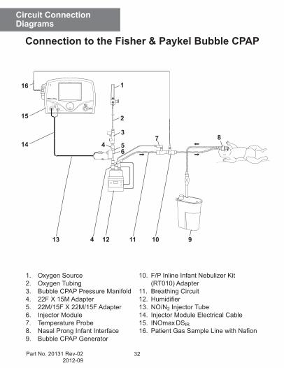
1. Oxygen Source2. Oxygen Tubing3. Bubble CPAP Pressure Manifold4. 22F X 15M Adapter5. 22M/15F X 22M/15F Adapter6. Injector Module7. Temperature Probe8. Nasal Prong Infant Interface9. Bubble CPAP Generator
10. F/P Inline Infant Nebulizer Kit (RT010) Adapter11. Breathing Circuit12. Humidifier13. NO/N2 Injector Tube14. Injector Module Electrical Cable15. INOmax DSIR16. PatientGasSampleLinewithNafion
10 912
8
11
15
3
54
2
7
13
14
116
6
4
Connection to the Fisher & Paykel Bubble CPAP
33 Part No. 20131 Rev-022012-09
Circuit ConnectionDiagrams
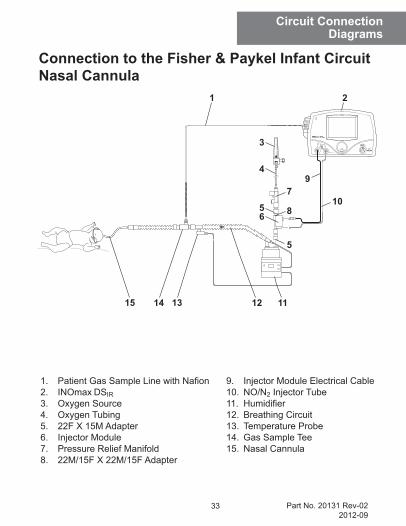
Connection to the Fisher & Paykel Infant Circuit Nasal Cannula
1. PatientGasSampleLinewithNafion2. INOmax DSIR3. Oxygen Source4. Oxygen Tubing5. 22F X 15M Adapter6. Injector Module7. Pressure Relief Manifold8. 22M/15F X 22M/15F Adapter
9. Injector Module Electrical Cable10. NO/N2 Injector Tube11. Humidifier12. Breathing Circuit13. Temperature Probe14. Gas Sample Tee15. Nasal Cannula
1
12 11
10
15 1314
2
65
79
4
3
8
5
34Part No. 20131 Rev-022012-09
Circuit ConnectionDiagrams
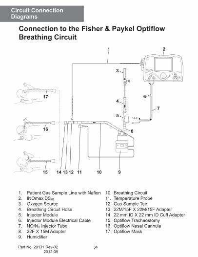
Connection to the Fisher & Paykel Optiflow Breathing Circuit
1. PatientGasSampleLinewithNafion2. INOmax DSIR3. Oxygen Source4. Breathing Circuit Hose5. Injector Module6. Injector Module Electrical Cable7. NO/N2 Injector Tube8. 22F X 15M Adapter9. Humidifier
10. Breathing Circuit11. Temperature Probe12. Gas Sample Tee13. 22M/15F X 22M/15F Adapter14. 22 mm ID X 22 mm ID Cuff Adapter15. OptiflowTracheostomy16. OptiflowNasalCannula17. OptiflowMask
1214 1115
21
75
46
3
8
910
16
17
13
35 Part No. 20131 Rev-022012-09
Circuit ConnectionDiagrams
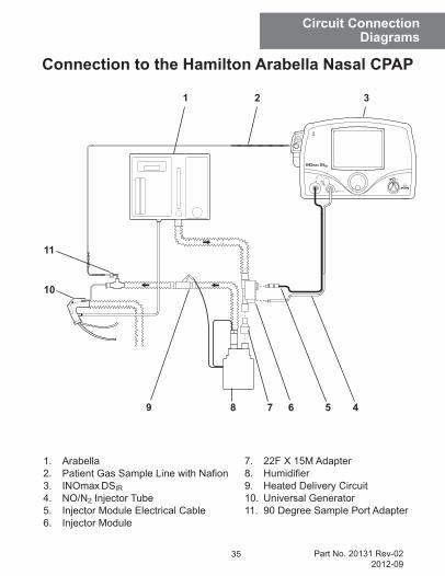
Connection to the Hamilton Arabella Nasal CPAP
1. Arabella2. PatientGasSampleLinewithNafion3. INOmax DSIR4. NO/N2 Injector Tube5. Injector Module Electrical Cable6. Injector Module
7. 22F X 15M Adapter8. Humidifier9. Heated Delivery Circuit10. Universal Generator11. 90 Degree Sample Port Adapter
8 7 5
31 2
9
11
10
6 4
36Part No. 20131 Rev-022012-09
Circuit ConnectionDiagrams
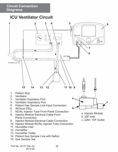
ICU Ventilator Circuit
1. Patient Wye2. Ventilator3. Ventilator Expiratory Port4. Ventilator Inspiratory Port5. Patient Gas Sample Line Input Connection6. INOmax DSIR7. NO/N2 Injector Tube Front Panel Connection8. Injector Module Electrical Cable Front Panel Connection9. Injector Module Electrical Cable Connection10. Injector Module NO/N2 Injector Tube Connection 11. HumidifierInlet 12. Humidifier 13. HumidifierOutlet14. PatientGasSampleLinewithNafion15. Gas Sample Tee
a. Injector Moduleb. 22F Inletc. 22M / 15F Outlet
b
ac
1 2 6
9
8
1011
3 4 5
7
12131415
37 Part No. 20131 Rev-022012-09
Circuit ConnectionDiagrams
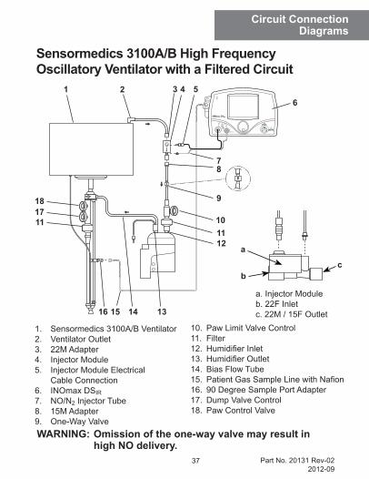
Sensormedics 3100A/B High Frequency Oscillatory Ventilator with a Filtered Circuit
1. Sensormedics 3100A/B Ventilator2. Ventilator Outlet3. 22M Adapter4. Injector Module5. Injector Module Electrical Cable Connection6. INOmax DSIR7. NO/N2 Injector Tube8. 15M Adapter9. One-Way Valve
1 2 46
10. Paw Limit Valve Control11. Filter12. HumidifierInlet13. HumidifierOutlet14. Bias Flow Tube15. PatientGasSampleLinewithNafion16. 90 Degree Sample Port Adapter17. Dump Valve Control18. Paw Control Valve
9
101112
15
11
13
1718
14
5
7
WARNING: Omission of the one-way valve may result in high NO delivery.
a. Injector Moduleb. 22F Inletc. 22M / 15F Outlet
b
a
c
3
8
16
38Part No. 20131 Rev-022012-09
Circuit ConnectionDiagrams
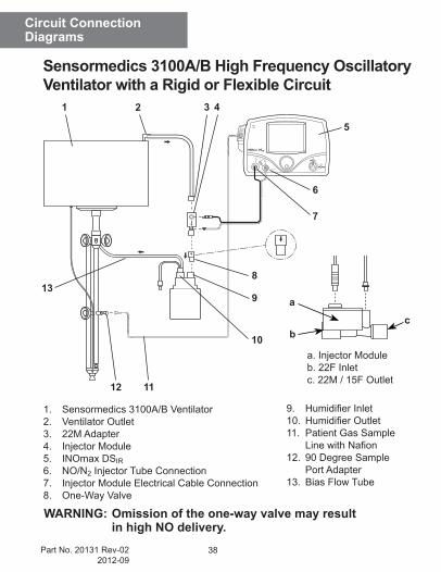
Sensormedics 3100A/B High Frequency Oscillatory Ventilator with a Rigid or Flexible Circuit
WARNING: Omission of the one-way valve may result in high NO delivery.
1. Sensormedics 3100A/B Ventilator2. Ventilator Outlet3. 22M Adapter4. Injector Module5. INOmax DSIR6. NO/N2 Injector Tube Connection7. Injector Module Electrical Cable Connection8. One-Way Valve
9. HumidifierInlet10. HumidifierOutlet11. Patient Gas Sample LinewithNafion12. 90 Degree Sample Port Adapter13. Bias Flow Tube
a. Injector Moduleb. 22F Inletc. 22M / 15F Outlet
b
a
c
1 2 4
5
6
7
8
9
10
11
13
12
3
39 Part No. 20131 Rev-022012-09
Circuit ConnectionDiagrams
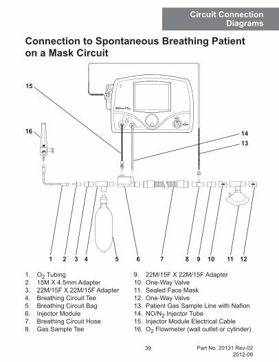
Connection to Spontaneous Breathing Patient on a Mask Circuit
1. O2 Tubing2. 15M X 4.5mm Adapter3. 22M/15F X 22M/15F Adapter4. Breathing Circuit Tee5. Breathing Circuit Bag6. Injector Module7. Breathing Circuit Hose8. Gas Sample Tee
9. 22M/15F X 22M/15F Adapter10. One-Way Valve11. Sealed Face Mask12. One-Way Valve13. PatientGasSampleLinewithNafion14. NO/N2 Injector Tube15. Injector Module Electrical Cable16. O2 Flowmeter (wall outlet or cylinder)
16
532 1061 7 12114 98
1314
15
40Part No. 20131 Rev-022012-09
Circuit ConnectionDiagrams
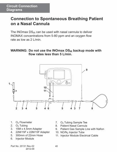
1. O2 Flowmeter2. O2 Tubing3. 15M x 4.5mm Adapter4. 22M/15F x 22M/15F Adapter5. 300mm of 22mm Hose6. Injector Module
Connection to Spontaneous Breathing Patient on a Nasal Cannula
4 5 432
1
6 5 34 7 8
1110
9
7. O2 Tubing Sample Tee8. Patient Nasal Cannula9. PatientGasSampleLinewithNafion10. NO/N2 Injector Tube11. Injector Module Electrical Cable
The INOmax DSIR can be used with nasal cannula to deliver INOMAXconcentrationsfrom5-80ppmandanoxygenflowrate as low as 2 L/min.
WARNING: Do not use the INOmax DSIR backup mode with flow rates less than 5 L/min.
41 Part No. 20131 Rev-022012-09
Circuit ConnectionDiagrams
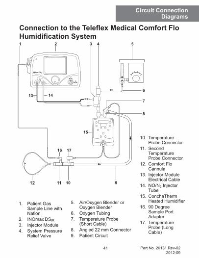
1. Patient Gas Sample Line with Nafion
2. INOmax DSIR3. Injector Module4. System Pressure
Relief Valve
5. Air/Oxygen Blender or Oxygen Blender
6. Oxygen Tubing7. Temperature Probe
(Short Cable)8. Angled 22 mm Connector9. Patient Circuit
10
17
14
31 2
11
16
912
Connection to the Teleflex Medical Comfort Flo Humidification System
4 5
6
7
8
15
13
10. Temperature Probe Connector
11. Second Temperature Probe Connector
12. Comfort Flo Cannula
13. Injector Module Electrical Cable
14. NO/N2 Injector Tube
15. ConchaTherm HeatedHumidifier
16. 90 Degree Sample Port Adapter
17. Temperature Probe (Long Cable)
42Part No. 20131 Rev-022012-09
Circuit ConnectionDiagrams
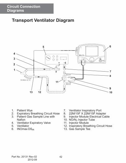
Transport Ventilator Diagram
1. Patient Wye2. Expiratory Breathing Circuit Hose3. Patient Gas Sample Line with Nafion4. Ventilator Expiratory Valve5. Ventilator6. INOmax DSIR
1
2
9
8
10
11
3
4
5
7
1213
6
7. Ventilator Inspiratory Port8. 22M/15F X 22M/15F Adapter 9. Injector Module Electrical Cable10. NO/N2 Injector Tube11. Injector Module12. Inspiratory Breathing Circuit Hose13. Gas Sample Tee

43 Part No. 20131 Rev-022012-09
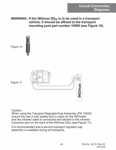
Circuit ConnectionDiagrams
WARNING: If the INOmax DSIR is to be used in a transport vehicle, it should be affixed to the transport mounting post part number 10009 (see Figure 10).
Figure 10
Figure 11
Caution:When using the Transport Regulator/Cap Assembly (PN 10022) ensure the cap is fully seated and in place on the INOmeter and the infrared cable is connected and latched to the infrared connector port on the back of the INOmax DSIR (see Figure 11).It is recommended that a second transport regulator cap assembly is available during all transports.
44Part No. 20131 Rev-022012-09
Circuit ConnectionDiagrams
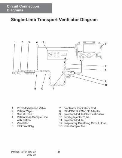
Single-Limb Transport Ventilator Diagram
1. PEEP/Exhalation Valve2. Patient Wye3. Circuit Hose4. Patient Gas Sample Line withNafion5. Ventilator6. INOmax DSIR
1 2
9
8
1011
3 4 5
7
1213
6
7. Ventilator Inspiratory Port8. 22M/15F X 22M/15F Adapter 9. Injector Module Electrical Cable10. NO/N2 Injector Tube11. Injector Module12. Inspiratory Breathing Circuit Hose13. Gas Sample Tee
45 Part No. 20131 Rev-022012-09
Circuit ConnectionDiagrams
WARNING: If the INOmax DSIR is to be used in a transport vehicle, it should be affixed to the transport mounting post part number 10009 (see Figure 10).
Figure 10
Figure 11
Caution:When using the Transport Regulator/Cap Assembly (PN 10022) ensure the cap is fully seated and in place on the INOmeter and the infrared cable is connected and latched to the infrared connector port on the back of the INOmax DSIR (see Figure 11).It is recommended that a second transport regulator cap assembly is available during all transports.
46Part No. 20131 Rev-022012-09
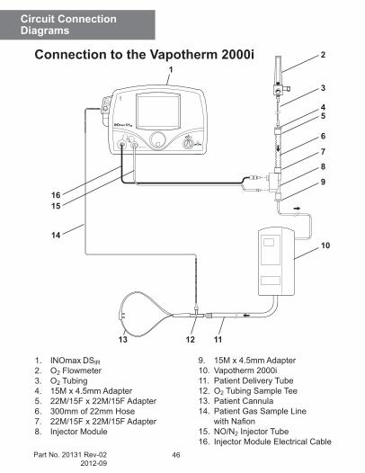
Circuit ConnectionDiagrams
1. INOmax DSIR2. O2 Flowmeter3. O2 Tubing4. 15M x 4.5mm Adapter5. 22M/15F x 22M/15F Adapter6. 300mm of 22mm Hose7. 22M/15F x 22M/15F Adapter8. Injector Module
10
1
14
12
9
8
1516
11
7
6
54
3
2
13
9. 15M x 4.5mm Adapter10. Vapotherm 2000i11. Patient Delivery Tube12. O2 Tubing Sample Tee13. Patient Cannula14. Patient Gas Sample Line withNafion15. NO/N2 Injector Tube16. Injector Module Electrical Cable
Connection to the Vapotherm 2000i
47 Part No. 20131 Rev-022012-09
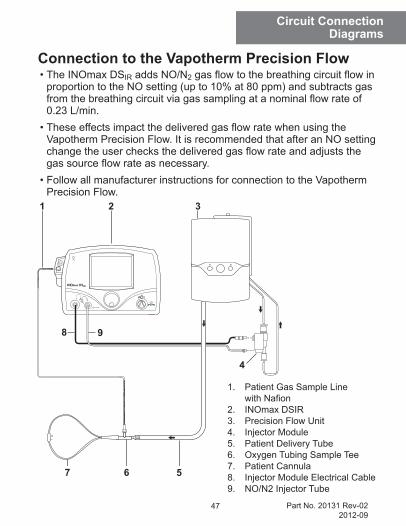
Circuit ConnectionDiagrams
1. Patient Gas Sample Line withNafion2. INOmax DSIR3. Precision Flow Unit4. Injector Module5. Patient Delivery Tube6. Oxygen Tubing Sample Tee7. Patient Cannula8. Injector Module Electrical Cable9. NO/N2 Injector Tube
5
31 2
6
9
7
Connection to the Vapotherm Precision Flow
4
8
•TheINOmaxDSIR adds NO/N2gasflowtothebreathingcircuitflowinproportion to the NO setting (up to 10% at 80 ppm) and subtracts gas fromthebreathingcircuitviagassamplingatanominalflowrateof0.23 L/min.
•TheseeffectsimpactthedeliveredgasflowratewhenusingtheVapotherm Precision Flow. It is recommended that after an NO setting changetheuserchecksthedeliveredgasflowrateandadjuststhegassourceflowrateasnecessary.
•FollowallmanufacturerinstructionsforconnectiontotheVapothermPrecision Flow.
48Part No. 20131 Rev-022012-09
Circuit ConnectionDiagrams
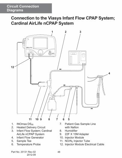
Connection to the Viasys Infant Flow CPAP System; Cardinal AirLife nCPAP System
1. INOmax DSIR2. Heated Delivery Circuit3. Infant Flow System; Cardinal AirLife nCPAP System4. Infant Flow Generator5. Sample Tee6. Temperature Probe
7. Patient Gas Sample Line withNafion8. Humidifier9. 22F X 15M Adapter10. Injector Module11. NO/N2 Injector Tube12. Injector Module Electrical Cable
4
1 3
12
7 6 510 8911
2
49 Part No. 20131 Rev-022012-09
Circuit ConnectionDiagrams
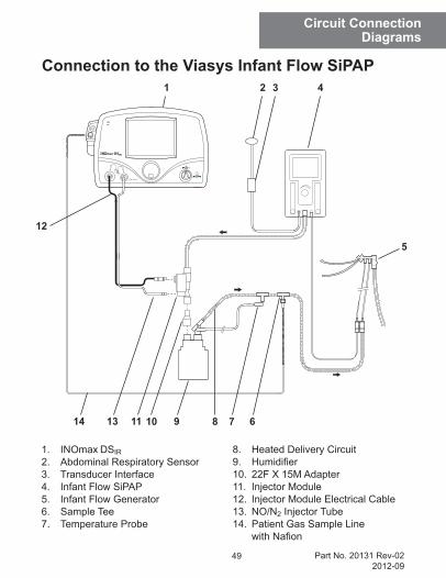
Connection to the Viasys Infant Flow SiPAP
1. INOmax DSIR2. Abdominal Respiratory Sensor3. Transducer Interface4. Infant Flow SiPAP5. Infant Flow Generator6. Sample Tee7. Temperature Probe
8. Heated Delivery Circuit9. Humidifier10. 22F X 15M Adapter11. Injector Module12. Injector Module Electrical Cable13. NO/N2 Injector Tube14. Patient Gas Sample Line withNafion
5
8 7 611 9
1 3 4
10
2
13
12
14
50Part No. 20131 Rev-022012-09
INOblender Circuit Connection Diagram
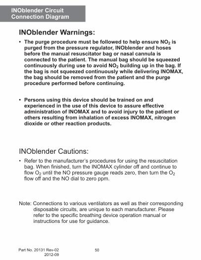
INOblender Warnings:• The purge procedure must be followed to help ensure NO2 is
purged from the pressure regulator, INOblender and hoses before the manual resuscitator bag or nasal cannula is connected to the patient. The manual bag should be squeezed continuously during use to avoid NO2 building up in the bag. If the bag is not squeezed continuously while delivering INOMAX, the bag should be removed from the patient and the purge procedure performed before continuing.
• Persons using this device should be trained on and experienced in the use of this device to assure effective administration of INOMAX and to avoid injury to the patient or others resulting from inhalation of excess INOMAX, nitrogen dioxide or other reaction products.
INOblender Cautions:• Refertothemanufacturer’sproceduresforusingtheresuscitationbag.Whenfinished,turntheINOMAXcylinderoffandcontinuetoflowO2 until the NO pressure gauge reads zero, then turn the O2 flowoffandtheNOdialtozeroppm.
Note: Connections to various ventilators as well as their corresponding disposable circuits, are unique to each manufacturer. Please refertothespecificbreathingdeviceoperationmanualorinstructions for use for guidance.
51 Part No. 20131 Rev-022012-09
INOblender Circuit Connection Diagram
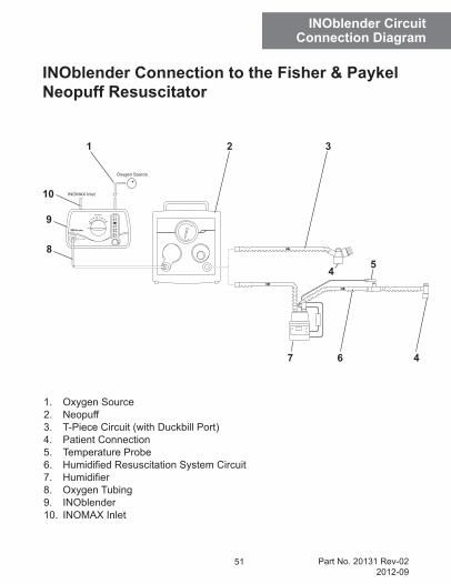
INOblender Connection to the Fisher & Paykel Neopuff Resuscitator
1. Oxygen Source2. Neopuff3. T-Piece Circuit (with Duckbill Port)4. Patient Connection5. Temperature Probe6. HumidifiedResuscitationSystemCircuit7. Humidifier8. Oxygen Tubing9. INOblender10. INOMAX Inlet
7 6
32
4
Oxygen Source
INOMAX Inlet
4 5
9
8
10
1
52Part No. 20131 Rev-022012-09
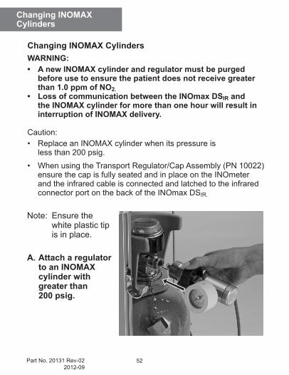
Note: Ensure the white plastic tip is in place.
A. Attach a regulator to an INOMAX cylinder with greater than 200 psig.
Changing INOMAXCylinders
WARNING: • A new INOMAX cylinder and regulator must be purged
before use to ensure the patient does not receive greater than 1.0 ppm of NO2.
• Loss of communication between the INOmax DSIR and the INOMAX cylinder for more than one hour will result in interruption of INOMAX delivery.
Caution: • ReplaceanINOMAXcylinderwhenitspressureis
less than 200 psig.• WhenusingtheTransportRegulator/CapAssembly(PN10022)
ensure the cap is fully seated and in place on the INOmeter and the infrared cable is connected and latched to the infrared connector port on the back of the INOmax DSIR.
Changing INOMAX Cylinders
53 Part No. 20131 Rev-022012-09
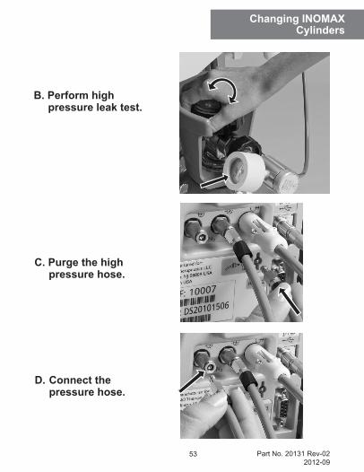
C. Purge the high pressure hose.
D. Connect the pressure hose.
Changing INOMAXCylinders
B. Perform high pressure leak test.
54Part No. 20131 Rev-022012-09
Changing INOMAXCylinders
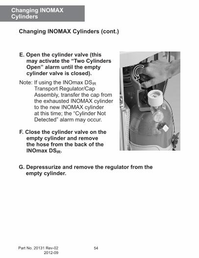
Changing INOMAX Cylinders (cont.)
E. Open the cylinder valve (this may activate the “Two Cylinders Open” alarm until the empty cylinder valve is closed).
Note: If using the INOmax DSIR Transport Regulator/Cap Assembly, transfer the cap from the exhausted INOMAX cylinder to the new INOMAX cylinder at this time; the “Cylinder Not Detected” alarm may occur.
F. Close the cylinder valve on the empty cylinder and remove the hose from the back of the INOmax DSIR.
G. Depressurize and remove the regulator from the empty cylinder.

55 Part No. 20131 Rev-022012-09
Changing INOMAXCylinders
(Intentionally left blank)
56Part No. 20131 Rev-022012-09
High CalibrationConnection Diagrams
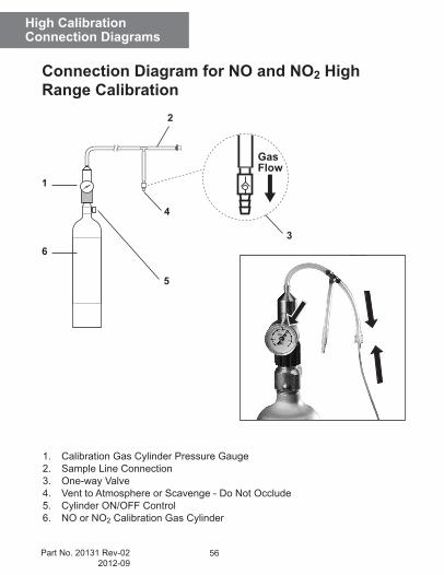
Connection Diagram for NO and NO2 High Range Calibration
1. Calibration Gas Cylinder Pressure Gauge2. Sample Line Connection3. One-way Valve4. Vent to Atmosphere or Scavenge - Do Not Occlude5. Cylinder ON/OFF Control6. NO or NO2 Calibration Gas Cylinder
1
6
2
3
4
5
57 Part No. 20131 Rev-022012-09
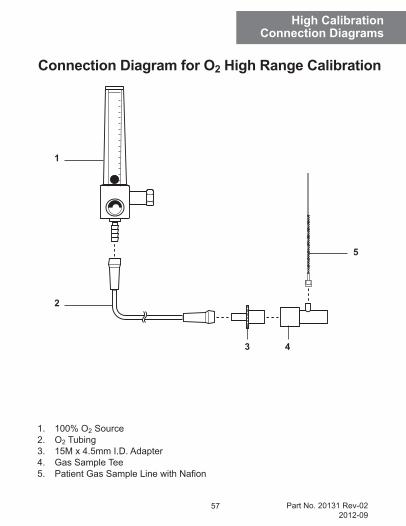
High CalibrationConnection Diagrams
Connection Diagram for O2 High Range Calibration
1. 100% O2 Source2. O2 Tubing3. 15M x 4.5mm I.D. Adapter4. Gas Sample Tee5. PatientGasSampleLinewithNafion
1
2
5
3 4
58Part No. 20131 Rev-022012-09
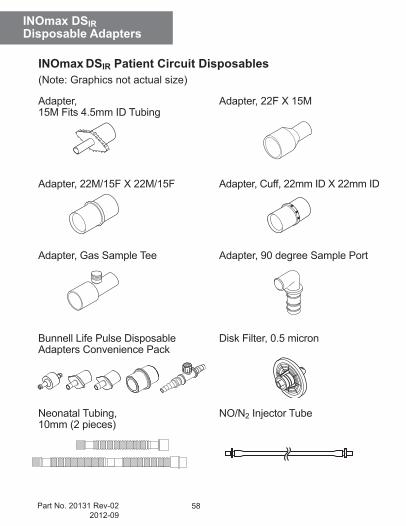
INOmax DSIRDisposable Adapters
INOmax DSIR Patient Circuit Disposables(Note: Graphics not actual size)
Adapter, Adapter, 22F X 15M15M Fits 4.5mm ID Tubing
Adapter, 22M/15F X 22M/15F Adapter, Cuff, 22mm ID X 22mm ID
Adapter, Gas Sample Tee Adapter, 90 degree Sample Port
Bunnell Life Pulse Disposable Disk Filter, 0.5 micronAdapters Convenience Pack
Neonatal Tubing, NO/N2 Injector Tube 10mm (2 pieces)
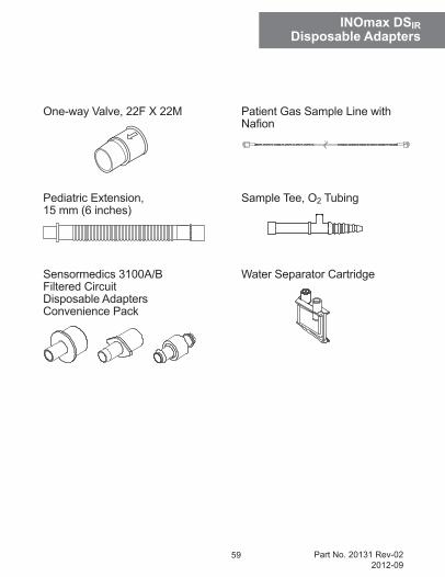
59 Part No. 20131 Rev-022012-09
One-way Valve, 22F X 22M Patient Gas Sample Line with Nafion
Pediatric Extension, Sample Tee, O2 Tubing15 mm (6 inches)
Sensormedics 3100A/B Water Separator CartridgeFiltered Circuit Disposable Adapters Convenience Pack
INOmax DSIRDisposable Adapters

60Part No. 20131 Rev-022012-09
INO Therapeutics d/b/a Ikaria, Inc.Perryville III Corporate Park
53 Frontage Road, Third FloorHampton, NJ 08827-9001, USA
1-877-566-9466