Embed Size (px)
Citation preview

PM36J6B10-01E_25
Yokogawa Electric Corporation 2-9-32 Nakacho, Musashino-shiTokyo, 180-8750JAPAN
Public Relations Dept., Yokogawa Electric CorporationCopyright © by Yokogawa Electric Corporation<date/time>
AOAAdvanced Operation Assistance
Solutions
July, 2003

PM36J6B10-01E_25Public Relations Dept., Yokogawa Electric CorporationCopyright © by Yokogawa Electric Corporation <date/time> Page 2
1. What is AOA ?

PM36J6B10-01E_25Public Relations Dept., Yokogawa Electric CorporationCopyright © by Yokogawa Electric Corporation <date/time> Page 3
What is the AOA ?
Upper solution of process operation done by operatorsTo assist daily work of production people to realize safer and more cost-effective operation. For example,– In desk work
• Support to prepare an operation report• Support to turn up operation related problems• Support to standardize operation know-how
– In normal operation• Suppress unnecessary DCS alarms to notify only important DCS alarms• Notify an early sign of abnormality faster than it is detected by DCS
alarms• Prevent miss-operation
– In transition operation (e.g. startup/load change/reactor switchover)
• Give an adequate instruction to the operator in a sequential order• Prevent miss-step/miss-procedure
Process
CONTROL domain OPERATION domain
MES, ERP
Process Control (DCS)
Advanced Process Control Advanced Operation Assistance
Process Operation (Operators)

PM36J6B10-01E_25Public Relations Dept., Yokogawa Electric CorporationCopyright © by Yokogawa Electric Corporation <date/time> Page 4
Difference between APC and AOA
APC (Advanced Process Control)– Position: Additional function of DCS– Purpose: Improvement of controllability– Configuration: Runs on additional PC– Main user: Engineering people– Approach: Based on mathematical process model– Benefit: More cost-effective control
AOA (Advanced Operation Assistance)– Position: Additional function of DCS– Purpose: Improvement of operation work– Configuration: Runs on operator’s console or additional
PC– Main user: Production people (operator/process
engineer)– Approach: Based on knowledge and experiences of
skillful operator/process engineer– Benefit: Safer and more cost-effective operation

PM36J6B10-01E_25Public Relations Dept., Yokogawa Electric CorporationCopyright © by Yokogawa Electric Corporation <date/time> Page 5
System architecture
Run on HIS or Additional PCSupports Windows2000/XPproServer/client configurationComponent software– Exaopc
(OPC interface package)– Exaplog
(Event reporting/analysis package)– Exapilot
(Operation efficiency improvement package)• Exapilot Professional or Standard• Advanced alarm function• MS Excel link icon
Support all DCS via OPCinterface
HISENG
FCS
V net
AOA Client
Ethernet
PC
PC
FCS
HF bus
ABC Busconverter
Setting
AOA Server
Gathering
Setting
Gathering
CENTUM-XL, VMicro XL
Event message
Gathering
(max. 4)
AOA Client
CENTUM CS 1000CENTUM CS 3000
Exaopc is required
System architecture(In case of additional PC)

PM36J6B10-01E_25Public Relations Dept., Yokogawa Electric CorporationCopyright © by Yokogawa Electric Corporation <date/time> Page 6
2. ExaplogEvent reporting and analysis package
2.1 Operation event viewer/analyzer2.2 Operation event reporter

PM36J6B10-01E_25Public Relations Dept., Yokogawa Electric CorporationCopyright © by Yokogawa Electric Corporation <date/time> Page 7
Assist desk work of production Dept.– Reporting of operational event– Monitoring of operational event– Analysis of operational event
Utilize a DCS alarm and event message which is less frequently used
Exaplog
Message Printer
HugeRunning Cost
HugeStorage Space
SpecialisticManual Work
Exaplog (Software Printer)
MinimumRunning Cost
MinimumStorage Space
Semi-automaticWork

PM36J6B10-01E_25Public Relations Dept., Yokogawa Electric CorporationCopyright © by Yokogawa Electric Corporation <date/time> Page 8
2.1 Operation event viewer/analyzer
5 viewers– Event balance trend (EBT)– Monthly/Weekly EBT– Category sort– Point ID (Tag) sort– Message summary
(same as DCS printer)
5 filters– Scope in– Exclude– Character– Process unit– User defined
Event balance trend (EBT) Category sort
Point ID sortMessage summary
Character/Process unit
User defined
Monthly/Weekly EBT

PM36J6B10-01E_25Public Relations Dept., Yokogawa Electric CorporationCopyright © by Yokogawa Electric Corporation <date/time> Page 9
Event balance trend (EBT)
Process Requests
Operator’s Actions
X-axis : Time (24hours)Y-axis : Number of events
Display the balance between– Process requests (+)
• System alarm• Process alarm• Annunciator message• Operation guidance, etc.
– Operators actions (-)• Tag data entry• Tag mode change, etc.
No. Pattern Type EBT Pattern Suspected Problem Countermeasure
Long term analysis about seasonal change
Long term analysis about erosion/corrosion
Unnecessary alarms/messages Retuning of alarm set valuesIntegration of redundant alarms/messagesMasking of low priolity alarms/messages
Low automation rate Automation using DCSManual operation according to know-how Automation using ExapilotComplex operation sequence Simplify operation sequence
Lack of support function Navigation using Exapilot
Insufficient Operator capability Operator training
Human error Error detection using Exapilot
Unstable process Introduction of advanced process control
Excessive Operation
Operator Work Overflow
Inadequate Operation
I
II
III
IV
V
No urgent problem
Redundant alarms/messages
Balanced
Excessive Nortification

PM36J6B10-01E_25Public Relations Dept., Yokogawa Electric CorporationCopyright © by Yokogawa Electric Corporation <date/time> Page 10
Category sort, Point ID sort
Category sort– Type– Sub type– Detail– Batch ID– Station
Point ID (Tag) sort– Tag– Tag + Detail

PM36J6B10-01E_25Public Relations Dept., Yokogawa Electric CorporationCopyright © by Yokogawa Electric Corporation <date/time> Page 11
2.2 Operation event reporting
Various reports can be exported to CSV file– Tag list which notifies many alarms
• Per detail (e.g. HH/HI/LO/LL/VEL/DEV/IOP)• Per priority (e.g. High/Medium/Low)• Per process unit (e.g. station#, process unit filter)
– Tag list which alarm set point have been changed
– AOF (alarm off) tag list– Manual control tag list, and more
Additional editing can be done using MS-ExcelUser defined report can be registered

PM36J6B10-01E_25Public Relations Dept., Yokogawa Electric CorporationCopyright © by Yokogawa Electric Corporation <date/time> Page 12
(4)
(1)Select “Sub Type” tub(2)Select “Tag Alarm”(3)Press “Scope in filter” button(4)Select “Tool\Export Result” to save a result of analysis as CSV file(5)Edit a report file using MS-Excel function
(1)
(2)
(3)
(5)
e.g. Tag list which notifies many alarms

PM36J6B10-01E_25Public Relations Dept., Yokogawa Electric CorporationCopyright © by Yokogawa Electric Corporation <date/time> Page 13
(1)Select “Detail” tub(2)Select “MAN”(3)Press “Scope in filter” button(4)Select “Tool\Export Result” to save a result of analysis as CSV file(5)Edit a report file using MS-Excel function
(1)
(2)
(3)
(4)
(5)
e.g. Tag list which controlled manually

PM36J6B10-01E_25Public Relations Dept., Yokogawa Electric CorporationCopyright © by Yokogawa Electric Corporation <date/time> Page 14
Benefits of Exaplog
Hidden problem can be revealed– Field related problem
• Failure of field instrumentation/equipment• Mismatch of field instrumentation/equipment• Range over of field instrumentation
– Control related problem• Mismatch of PID parameters
– Alarm related problem• Unnecessary HI/LO alarm caused by mismatched alarm thresho
ld/hysteresis• Unnecessary IOP alarm caused by range over• Nuisance Annunciator message related to DI/SW
– Operation related problem• Complex manual operation• Miss-operation

PM36J6B10-01E_25Public Relations Dept., Yokogawa Electric CorporationCopyright © by Yokogawa Electric Corporation <date/time> Page 15
Pharmaceutical plant, USA
The background– Large batch chemical plant– Legacy system was replaced to CS3000– Over 10,000 I/O
The problem– 50,000 alarms per day– Audible alarms were disabled
• Operators where missing critical alarms• Alarms were disappearing from display in 10
minutes• Lost production• Increased safety hazards• Increased production cost

PM36J6B10-01E_25Public Relations Dept., Yokogawa Electric CorporationCopyright © by Yokogawa Electric Corporation <date/time> Page 16
The approach– Use Six Sigma methodology– Set overall goal of 10 alarms/day– Use Exaplog to measure and analyze alarms
The result– Cut the alarming rate by a 98%
• Field improvement– Improvement of field instrumentations (re-ranging)
• Alarm optimization and management– Elimination of nuisance Opeguide messages– Retuning of alarm threshold
– Two of the four operator stations back on-line– Operator mistakes have decreased– Productivity has increased by notification of adequate
alarms– Operating issues around several pieces of equipments
have been resolved by systematic alarm analysis
PM36J6B10-01E_25Public Relations Dept., Yokogawa Electric CorporationCopyright © by Yokogawa Electric Corporation <date/time> Page 17
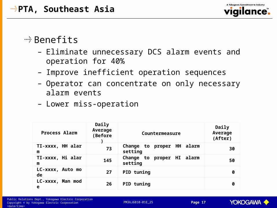
PTA, Southeast Asia
Benefits– Eliminate unnecessary DCS alarm events and
operation for 40%– Improve inefficient operation sequences– Operator can concentrate on only necessary alarm
events– Lower miss-operation
Process AlarmDaily
Average (Before)
TI-xxxx, HH alarm 73 30
TI-xxxx, Hi alarm 145 Change to proper HI alarm setting 50
LC-xxxx, Auto mode 27 PID tuning 0
LC-xxxx, Man mode 26 PID tuning 0
Change to proper HH alarm setting
CountermeasureDaily
Average (After)

PM36J6B10-01E_25Public Relations Dept., Yokogawa Electric CorporationCopyright © by Yokogawa Electric Corporation <date/time> Page 18
3. ExapilotOperation efficiency improvement package

PM36J6B10-01E_25Public Relations Dept., Yokogawa Electric CorporationCopyright © by Yokogawa Electric Corporation <date/time> Page 19
Exapilot
Additional DCS function for– Knowledge-based process control– Knowledge-based process monitoring
Application can be programmed as flow chart or logic chart– Specialist programming skill is not needed– High usability– High understandability– High maintainability
Existing application in DCS is no need to modify
Various usages– Automation of transient operation– Alarm management– Operator training

PM36J6B10-01E_25Public Relations Dept., Yokogawa Electric CorporationCopyright © by Yokogawa Electric Corporation <date/time> Page 20
Flow chart programming tool (Standard)
Visible iconsfor flow chart program
Application example
Application example

PM36J6B10-01E_25Public Relations Dept., Yokogawa Electric CorporationCopyright © by Yokogawa Electric Corporation <date/time> Page 21
Logic chart programming tool (Option)
Application example
Grammar of logic chart
Visible iconsfor logic chart program

PM36J6B10-01E_25Public Relations Dept., Yokogawa Electric CorporationCopyright © by Yokogawa Electric Corporation <date/time> Page 22
Ready-made templates
For flow chart
For logic chart

PM36J6B10-01E_25Public Relations Dept., Yokogawa Electric CorporationCopyright © by Yokogawa Electric Corporation <date/time> Page 23
3.1 Automation of transient operation

PM36J6B10-01E_25Public Relations Dept., Yokogawa Electric CorporationCopyright © by Yokogawa Electric Corporation <date/time> Page 24
Builder function
<Condition icon>Check LI100.PV>=50
<Block mode setting icon>P101.MODE to AUTO
<Condition icon>Check P101.PV = 2
<Output to DCS icon>P101.CSV to 2 (Start)
<Confirmation icon>HV100 Open
<Guidance message icon>P101 start finished
<Condition icon>Check P101.ALRM = NR(NR means Normal)
<Output to DCS icon>P101.CSV to 0 (Stop)
<Alarm message icon>P101 start error
<Pause icon>Pause this sequence
<Alarm message icon>Preparation error
<Output to DCS icon>FIC100.SV to 20t/h
<Timer icon>Wait 10 minutes
YES YES
NONO
NOYES
Typical paper SOP
Know-how
Know-how
(1) Check base tank level LI100.PV >= 50%(2) Start pump P-101(3) Check answer back flag(4) open field hand valve HV100
Typical paper SOP (too much simplified)
If tank level is lower than 50%, announce it and open inlet valve of base tank (FIC100.SV = 20t/h), and wait for 10 minutes. If answerback is not ‘2’ and alarm status (P101.ALRM) is not “NR”, stop pump (P101.CSV = 0), announce it, and pause operation till field operator solves the problem.
Operation know-how of veteran operator/engineer
An automation program can be easily created as flow chart diagram including a veteran operator’s/engineer’s know-how.

PM36J6B10-01E_25Public Relations Dept., Yokogawa Electric CorporationCopyright © by Yokogawa Electric Corporation <date/time> Page 25
Operation function
1. Icons’ color means the condition. Green:Now executing Gray:Finished White:Unexecuted Yellow:Paused
1 2 3 4
1 2 3 4 5 6 7 8
Flow chart diagram can be executed automaticallyInteractive operation between Exapilot and operators can be doneVarious kinds of messages makes operators right judgmentOperational status can be confirmed visuallyManual interposition by operators can be done according to need
2. Four kinds of messages display. 1)Confirm 2)Guide 3)Alarm 4)System
3. Manual operation is available. 1)Start all 2)Start icon 3)Stop icon 4)Pause (all/icon) 5)Initialize icon 6)Break icon 7)Skip icon 8)Stop all

PM36J6B10-01E_25Public Relations Dept., Yokogawa Electric CorporationCopyright © by Yokogawa Electric Corporation <date/time> Page 26
Benefits
Safety improvement– Prevention of miss-operation– Prevention of hazardous situation by the early
detection of process abnormality
Productivity improvement– Improvement of product quality– Increase of production by shortening of operation
time– Reduction of transient (off-specification) product
Cost saving– Utility saving (steam, fuel gas, electricity,
instrumentation air)– Saving of inventory management cost– Reduction of operator’s workload– Reduction of engineering workload

PM36J6B10-01E_25Public Relations Dept., Yokogawa Electric CorporationCopyright © by Yokogawa Electric Corporation <date/time> Page 27
Application examples1. Crude unit, Japan2. BTX, Japan3. Polyethylene/Polypropylene, Japan4. Olefin, Japan5. Ethylene, Japan6. PTA, Southeast Asia7. ABS/AS, Taiwan8. Soda ash, USA9. High purified alcohol, Japan10. Ethyl-benzene, Japan

PM36J6B10-01E_25Public Relations Dept., Yokogawa Electric CorporationCopyright © by Yokogawa Electric Corporation <date/time> Page 28
(1) Crude unit, Japan
Problems– Operator’s workload is higher than in a normal
operation• Twice or three times a week• 130 DCS manipulations/switchover
– Operation time and product quality depends on a skill of assigned operator
• Three hours difference• Utility was also wasted
Engineering– 4 applications
• Adjust process load before switchover• Switch crude oil from LGO to HGO• Switch crude oil from HGO to LGO• Heat up, Air in
– Skilful operator:2 man-months for making main procedure
Automation of crude switchover operation

PM36J6B10-01E_25Public Relations Dept., Yokogawa Electric CorporationCopyright © by Yokogawa Electric Corporation <date/time> Page 29
Difference of ramping technique
Junior operators– Ramps up SV of feed temperature linearly in a same rate
Veteran operators– Changes the ramping rate according to the zone of
temperature• From 40 degree to 45 degree (First stage)
– Change “MODE” from “AUT” to “MAN”– Change “MV”– Return “MODE” from “MAN” to “AUT” (Repetition)
• From 180 degree to 185 degree (Final stage)– Control in “AUT” mode mainly– Change “MV” in case a deviation between SV and PV is remaining for
long time– Desensitize (change) PID parameters to prevent the over shoot
45-50yrs 42%
41-45yrs 20%
36-40yrs 9%
31-35yrs 6%
26-30yrs 17%21-25yrs 6%
Veteran operators

PM36J6B10-01E_25Public Relations Dept., Yokogawa Electric CorporationCopyright © by Yokogawa Electric Corporation <date/time> Page 30
Benefits
90% of manual operations were automatedAll monitoring works were automated2000 unnecessary alarms were suppressed– Operators can do another work during crude switchover
operation– Miss-step and miss-procedure were prevented from
occurring– Safer operation was achieved
0
50
100
150
200
250
Crude switch 151 116 106
Normal 50 50 50
LGO to HGO HGO to LGO LGO to HGO
31March 2April 5April
0
50
100
150
200
250
Crude switch 15 15 15
Normal 50 50 50
LGO to HGO HGO to LGO LGO to HGO
31March 2April 5April
Done by operator Done by Exapilot
Number of DCS tough operation by operators

PM36J6B10-01E_25Public Relations Dept., Yokogawa Electric CorporationCopyright © by Yokogawa Electric Corporation <date/time> Page 31
Benefits
Operating time was shortenedProduct quality was improved– Operation cost was reduced
Adjust process load4:00-9:30
(Manual operation)
Switchover9:30-12:30(Manual)
Switchover9:30-11:30
(Automatic)
Crude Charge (A train)
Crude Charge (B train)
Separator Level
Separator Flow
Stripper LevelStripper Extract Flow
Dryer Bottom Level
Product Flow
LGO to HGO Operator comes to work at 8:30to do another work
Operator comes to work at 4:00to start the preparation work
Done by operator (manual) Done by Exapilot (automatic)
Adjustprocess load
7:00-9:30(Automatic)

PM36J6B10-01E_25Public Relations Dept., Yokogawa Electric CorporationCopyright © by Yokogawa Electric Corporation <date/time> Page 32
(2) BTX plant, Japan
Process– BTX (Benzene, Toluene, Xylene) plant
• Mixture of law material (Crude gas oil)• Distillation (Extraction of impurities)• Hydro treating• Extraction (Dissolution of BTX)• Recovery• Distillation (Constituent separation of BTX)
System configuration– CENTUM-XL with ABC– Exapilot on HIS
Automation of heuristics control in Benzene tower

PM36J6B10-01E_25Public Relations Dept., Yokogawa Electric CorporationCopyright © by Yokogawa Electric Corporation <date/time> Page 33
Target operation– Process load control– NA density control in intermediate tank– Ratio control of solvent in case of
composition fluctuation– Temperature monitoring of air fin– Specific productivity monitoring of utility
• Fuel gas, steam, electric power
Engineering– 1 veteran operator– 2 months (July to August in 2002)

PM36J6B10-01E_25Public Relations Dept., Yokogawa Electric CorporationCopyright © by Yokogawa Electric Corporation <date/time> Page 34
Benefits– Reduction of operator’s workload
• From 34 times/day to 3 times/day
– Improvement of product quality
Before use (SD = 0.0011)
After use (SD = 0.0008)
Density of Benzene (%)
Upper limit
Lower limit

PM36J6B10-01E_25Public Relations Dept., Yokogawa Electric CorporationCopyright © by Yokogawa Electric Corporation <date/time> Page 35
(3) Polyethylene plant, Japan
Purpose of introduction– Reduction of operator’s workload
• Three hours everyday• 200 DCS manipulations/operation• Process monitoring is required continuously
– Shortening of operation time– Reduction of transient products
• Operating time depends on assigned operator• Quantity of transient products depends on assigned
operator– In case of junior operator: +50% of average– In case of skilful operator: -20% of average
– Standardization of control method• Overshoot control is required to shorten operation time
Automation of grade changeover operation
Ukishima factory (CENTUM CS 3000)• PP (Bulk polymerization) 70,600 ton/year (KPP1)• PP (Bulk polymerization) 67,000 ton/year (KPP2)
Chidori factory (CENTUM-XL) PP (Vapor phase polymerization) 89,100 ton/year (KPP3) HDPE (Slurry polymerization) 45,000 ton/year (KHD1) HDPE (Slurry polymerization) 50,200 ton/year (KHD2)

PM36J6B10-01E_25Public Relations Dept., Yokogawa Electric CorporationCopyright © by Yokogawa Electric Corporation <date/time> Page 36
Why not automated using DCS function ?– Difficulty of programming
• Only skilful operators and process engineers know the best procedure experientially
• It is difficult for DCS engineers to import all of their know-how into DCS program
– Frequent modification of program is required• Addition of new experiences is often necessary
– Inheritance of operation know-how is required• DCS program is difficult for operators to understand

PM36J6B10-01E_25Public Relations Dept., Yokogawa Electric CorporationCopyright © by Yokogawa Electric Corporation <date/time> Page 37
Engineering– 8 months/200 applications-plant– Skilful operator inputs his experiences into Exapilot– Process engineer temporary supports operators

PM36J6B10-01E_25Public Relations Dept., Yokogawa Electric CorporationCopyright © by Yokogawa Electric Corporation <date/time> Page 38
Benefits– Reduction of operator’s workload
• Operation was fully automated• Any miss-operation was prevented
– Operating time was optimized• 10% shortened on the average
– Transition products were reduced• 20% reduced on the average
– Engineering workload was reduced• 90% reduced in comparison with that for DCS
– Operation know-how was shared
PM36J6B10-01E_25Public Relations Dept., Yokogawa Electric CorporationCopyright © by Yokogawa Electric Corporation <date/time> Page 39
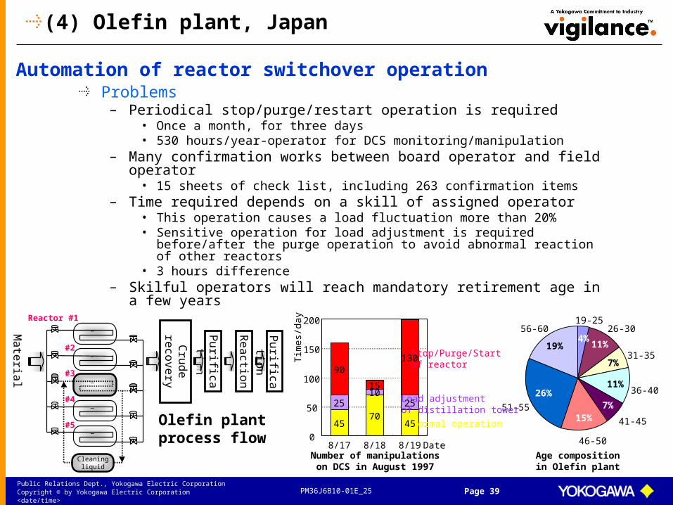
(4) Olefin plant, Japan
Problems– Periodical stop/purge/restart operation is required
• Once a month, for three days• 530 hours/year-operator for DCS monitoring/manipulation
– Many confirmation works between board operator and field operator
• 15 sheets of check list, including 263 confirmation items– Time required depends on a skill of assigned operator
• This operation causes a load fluctuation more than 20%• Sensitive operation for load adjustment is required before/after the
purge operation to avoid abnormal reaction of other reactors• 3 hours difference
– Skilful operators will reach mandatory retirement age in a few years
Automation of reactor switchover operation
19-2526-30
31-35
36-40
41-45
46-50
51-55
56-604%
11%
7%
11%
7%15%
26%
19%
Age compositionin Olefin plant
Cleaningliquid
Ma
teria
l
Reactor #1_
#2_
#3_
#4_
#5_
Cru
de
reco
very
Pu
rificatio
n
Re
actio
n
Olefin plantprocess flow 0
50
100
150
200
8/17 8/18 8/19 Date
Tim
es/d
ay
Stop/Purge/Startof reactor
Load adjustmentof distillation tower
Normal operation
Number of manipulationson DCS in August 1997
90
25
45
1510
70
130
25
45
Pu
rificatio
n

PM36J6B10-01E_25Public Relations Dept., Yokogawa Electric CorporationCopyright © by Yokogawa Electric Corporation <date/time> Page 40
Buying motivation of Exapilot– More flexible than DCS
• Changeover of operational procedure can be done online depending on a situation (pause, restart, bypass)
• Interactive operation can be done• Combination with existing DCS program
– Easier than DCS• Special skill for engineering is not necessary• Operator/process engineer can directly input their know-
how• Frequent modification is possible
Schedule– Decision of introduction in December 1997– Beginning of operation in June 1998
Engineering– DCS engineer: 0.8 man-months for making user-defined
procedure modules– Chief operator: 1.3 man-months for making main
procedure– Efficiency of engineering is 1/10 in comparison with DCS

PM36J6B10-01E_25Public Relations Dept., Yokogawa Electric CorporationCopyright © by Yokogawa Electric Corporation <date/time> Page 41
Application example– Automation of reactor depressurisation
• Extract liquid/gas to downstream in order to reduce inlet pressure when reactor is stopped
• In case of junior operator, it takes long time to depress inlet pressure for fear of process fluctuation
• In case of skilful operator, he can immediately depress inlet pressure by monitoring pressure and flow of downstream so that process load of downstream becomes upper limitation constantly
• Operation time was reduced from 5 hours to 2.5 hours– Automation of reactor pressurisation
• Operation time was reduced 30 minutes– Automation of feed control during start up operation
• Feed flow of other reactors is fluctuated according to the fluctuation of header pressure while operator ramps up load of feed compressor to start up purged reactor, and it causes mental distress to the operators due to the possibility of abnormal reaction
• Stable control was realized

PM36J6B10-01E_25Public Relations Dept., Yokogawa Electric CorporationCopyright © by Yokogawa Electric Corporation <date/time> Page 42
Benefits– Reduction of operator’s workload
• Full automation of board operation was achieved• 290 manipulations were reduced in each purge operation• 410 hours/year were reduced including monitoring work
– Increase of productivity• 3 hours shortened in each purge operation
(150hours/year)• Productivity was increased 200 ton/year
– Prevention of miss-operation• Check list was eliminated
– Reduction of mental distress– Succession of operation know-how
0
50
100
150
200
250
8/17 8/18 8/19Num
ber
of
Op
era
tion
s o
n D
CS
pe
r D
ay
Before automation(August 1997)
0
50
100
150
200
250
7/14 7/15 7/16
After automation(July 1998)
BeforeAutomation
600
500
400
300
200
100
0
Tim
e / M
an Y
ear
AfterAutomation
Operating Timeon DCS
Operating Time on DCS
Monitoring Timeon DCS
Monitoring Time on DCS
530
120

PM36J6B10-01E_25Public Relations Dept., Yokogawa Electric CorporationCopyright © by Yokogawa Electric Corporation <date/time> Page 43
(5) Ethylene plant, Japan
Process– Ethylene plant
• 374,000 ton/year
System configuration– CENTUM-V with ABC (Bus converter)
Target operation– Naphtha Evaporation
• Stabilization Control– Naphtha Cracking Furnace
• Decoking Operation– Naphtha Cracking Furnace
• Oil Combustion Start/Stop– GT Hot Wash Operation– EMG Secondary Operation
Automation of decoking related operation

PM36J6B10-01E_25Public Relations Dept., Yokogawa Electric CorporationCopyright © by Yokogawa Electric Corporation <date/time> Page 44
Process– Ethylene plant
• 374,000 ton/year
System configuration– CENTUM-V with ABC (Bus
converter)
Target operation– Naphtha Splitter
• FRN Tank Switchover Operation• Start Up/Shut Down Operation• Charge Control
– BT Unit• Start Up/Shut Down
– Ethylene• Start Up/Shut Down
Automation of Naphtha switchover operation
PM36J6B10-01E_25Public Relations Dept., Yokogawa Electric CorporationCopyright © by Yokogawa Electric Corporation <date/time> Page 45
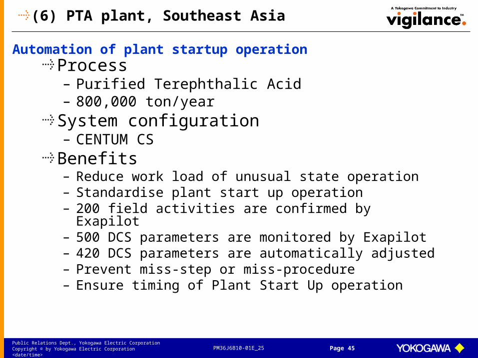
(6) PTA plant, Southeast Asia
Process– Purified Terephthalic Acid– 800,000 ton/year
System configuration– CENTUM CS
Benefits– Reduce work load of unusual state operation– Standardise plant start up operation– 200 field activities are confirmed by Exapilot– 500 DCS parameters are monitored by Exapilot– 420 DCS parameters are automatically adjusted– Prevent miss-step or miss-procedure– Ensure timing of Plant Start Up operation
Automation of plant startup operation

PM36J6B10-01E_25Public Relations Dept., Yokogawa Electric CorporationCopyright © by Yokogawa Electric Corporation <date/time> Page 46
Many DCS parameters are monitored and adjusted by Exapilot
Heating by junior operator Heating by Exapilot

PM36J6B10-01E_25Public Relations Dept., Yokogawa Electric CorporationCopyright © by Yokogawa Electric Corporation <date/time> Page 47
(7) ABS plant, Taiwan
Process– AS plant– 50% Polymer of acrylic nitrile and styrene monomer– Low material of ABS– 12 hours startup/shutdown
System configuration– CENTUM-XL via ABC
Objectives– Full automation for plant startup and shutdown– Shorter, safer startup and shut down– Better quality control in startup and shutdown
Automation of plant startup/shutdown operation

PM36J6B10-01E_25Public Relations Dept., Yokogawa Electric CorporationCopyright © by Yokogawa Electric Corporation <date/time> Page 48
Implementation approach– Smart ramp and soak design for feed– Model based temperature control to treat
long dead time characters– Adaptive gain to handle changing process
gain– Optimum switchover of PID algorithm to
avoid startup overshoot• i.e. PI to PD to PID
– Polymer reaction temperature profile setting
– Set point swift to avoid temperature run away
– Nonlinear valve plug compensation

PM36J6B10-01E_25Public Relations Dept., Yokogawa Electric CorporationCopyright © by Yokogawa Electric Corporation <date/time> Page 49
Engineering– Manpower: 4 supervisors and engineers
from customer 4 engineers from vender– Term: 6 months
Benefits– Reduction of operator’s work load
• From 400 DCS manipulations to 3 Exapilot operations
– Improvement of process performance– Shortening of startup/shutdown time

PM36J6B10-01E_25Public Relations Dept., Yokogawa Electric CorporationCopyright © by Yokogawa Electric Corporation <date/time> Page 50
(8) Sodium carbonate decahydrate, USA
Process– Sodium carbonate decahydrate
• Two crystallizers• Refrigeration system• Vacuum controls for barometric condenser• Pusher centrifuge• Crystallizer heating system• Numerous pump and tanks
– New process and new operators– Many field operations
System configuration– CENTUM CS 3000
• FCS x 1, HIS x 2• 162 control loops• 2 operators/shift
Automation of plant startup operation

PM36J6B10-01E_25Public Relations Dept., Yokogawa Electric CorporationCopyright © by Yokogawa Electric Corporation <date/time> Page 51
Engineering– Manpower: 1.5 man-month– Term: 1 month
Application– 300 icons– 24 sub-procedures– 5 seconds– 52 field activities are confirmed– 44 DCS parameters are monitored– 90 DCS parameters are automatically
adjusted
Builder window
Operation window

PM36J6B10-01E_25Public Relations Dept., Yokogawa Electric CorporationCopyright © by Yokogawa Electric Corporation <date/time> Page 52
Benefits– Guides the operator through every step of the procedure. Ver
y user friendly.– Much easier to implement the procedure than in the DCS– Expect reduction in operating time, operator work load, and
miss-operation.– Procedures are fully documented as part of the development
process.– Easy to update and optimize the procedure as the process k
nowledge improves.i.e. the best operating knowledge is retained.
– Operator training for both off-line and on-line
Future application– 6 Calciner refractory cure procedures– 4 MVR Crystallizer startup procedures– 2 Boiler Startup & Shutdown Procedures

PM36J6B10-01E_25Public Relations Dept., Yokogawa Electric CorporationCopyright © by Yokogawa Electric Corporation <date/time> Page 53
(9) High purified alcohol plant, Japan
Process– High purified alcohol plant– Different 9 distillation towers
System configuration– CENTUM CS 3000
Problems– Two different start up procedures
due to the season changes– High frequency operation (every 3 weeks)– Start up procedure depends on each
distillation tower– Many manual operation to control pressure
and temperature
Automation of plant startup operation

PM36J6B10-01E_25Public Relations Dept., Yokogawa Electric CorporationCopyright © by Yokogawa Electric Corporation <date/time> Page 54
Engineering– Manpower: 8 man-month
• 2 veteran operators (1.5 man-month)• 2 process engineers (0.5 man-month)
– Term: 6 weeks
Benefits– Reduce manual operation– Reduce engineering workload– Prevent miss-step or miss-procedure– Operation know-how is standardized

PM36J6B10-01E_25Public Relations Dept., Yokogawa Electric CorporationCopyright © by Yokogawa Electric Corporation <date/time> Page 55
(10) Ethyl-benzene plant, Japan
Process– Ethyl-benzene– Frequency: 2-3 times/year
System configuration– CIEMAC via Exaopc (OPC interface)
Problems– High intensity work
• Takes for 2 weeks• 2,300 DCS manipulations• Operated with normal operation in parallel
– Typical heuristics operation
Automation of regeneration operation of alkylation catalyst

PM36J6B10-01E_25Public Relations Dept., Yokogawa Electric CorporationCopyright © by Yokogawa Electric Corporation <date/time> Page 56
Engineering– Mid-level operator
Benefits– Reduction of operator’s work load
• 90% reduction of DCS manipulations done by operator
– Standardization of complex operation know-how

PM36J6B10-01E_25Public Relations Dept., Yokogawa Electric CorporationCopyright © by Yokogawa Electric Corporation <date/time> Page 57
3.2 Alarm Management
(1) Masking of unnecessary DCS alarm(2) Dynamic alarm setting(3) Addition of pre-alert(4) Replacement to advanced alarm(5) Prevention of miss-operation
Under development (will be released in Feb. 2004)

PM36J6B10-01E_25Public Relations Dept., Yokogawa Electric CorporationCopyright © by Yokogawa Electric Corporation <date/time> Page 58
What is required to the alarm system ?
For safer and more cost-effective operation of industrial systems– To help the operator to correct potentially dangerous
situations before the ESD is forced to intervene– To recognize and act to avoid hazardous situations– To identify deviations from desired operating conditions
that could lead to financial loss– To better understand complex process conditions
An effective alarm system
TargetNormalUpsetShutDown
Key Alarm Information
X X
XX X X X X X
XXXXXXXX
X X
XX X X X X X
XXXXXXXX
X XPlant State
ESDneeded
Operatorinterventionneeded
Minor operatingadjustmentneeded
X = Alarm
EEMUA No.191

PM36J6B10-01E_25Public Relations Dept., Yokogawa Electric CorporationCopyright © by Yokogawa Electric Corporation <date/time> Page 59
20152 alarms/day
Refinery Phenol plant
5274 alarms/day
Unnecessary alarms notified despite safe or efficient operationNecessary alarms not notified despite unsafe or inefficient operation(it’s not general because alarm must be set narrowly for safety reasons)
However, in fact…
Demand to additional alarm management function
5471 alarms/day
PTA plant
An ineffective alarm system
TargetNormalUpsetShutDown
Key Alarm Information
X XXX X X
X
X
XX
XXXX
XX
X
XX
XX
XX
X XX
X
X XX
XX
X
XX X
Plant StateESD
needed
Operatorinterventionneeded
Minor operatingadjustmentneeded
X = Alarm
EEMUA No.191

PM36J6B10-01E_25Public Relations Dept., Yokogawa Electric CorporationCopyright © by Yokogawa Electric Corporation <date/time> Page 60
(1) Masking of unnecessary DCS alarm
Masking of unnecessary HI/LO alarm– Because alarm threshold is unmatched
Masking of longstanding false HI/LO alarm– Because alarm hysteresis parameter is unmatched
Re-activation of longstanding true HI/LO alarm– Because still function of CENTUM is not used
Masking of oscillation HI/LO alarm– Because PID parameters are unmatched
Masking of repeating annunciator message– Because appropriate DCS sequence (delay timer) is not prepared
Masking of unnecessary IOP/IOP- alarm– Because tag range is unmatched (range over)
Fault diagnosis for necessary IOP/IOP- alarm– Because field transmitter is failed– Because wire is come down
1. Detect and suppress unnecessary DCS alarms automatically2. Display the reason of occurrence as countermeasure3. Report a suppressed alarms list

PM36J6B10-01E_25Public Relations Dept., Yokogawa Electric CorporationCopyright © by Yokogawa Electric Corporation <date/time> Page 61
A) Repeating HI/LO alarm (masking logic)
Monitoring period
Note) Mean: PV moving average, Dev: PV standard deviation, SH: Scale HI, SL: Scale LO, A: parameter (default=2)
(1) IF New_PH = Mean - 3 x Dev >= Original_PL + 0.1 x (SH - SL) & |New_PH - Mean| >= |Original_PH - Mean|
THEN New_PH = Mean - 3 x Dev
(2) IF New_PH = Mean - 3 x Dev <= Original_PL + 0.1 x (SH - SL) & |New_PH - Mean| >= |Original_PH - Mean|
THEN New_PH = Mean - A x Dev
SL
SH
Original_PH
Original_PL
Start monitoring
1 2 3
New_PH
Number of occurrence
HI HI HI
Time
PV
Start
masking
Purpose
This logic can mask an unnecessary HI/LO alarm which is slowly oscillating near PH/PL.
Logic
This logic consists of “monitoring” logic, “masking” logic and “recovery” logic. Monitoring logic is started when first HI/LO alarm is occurred, and then monitors the number of occurrence while ordered monitoring period. In case the number reaches an ordered times, masking logic is run.
Masking logic
PH/PL is automatically changed so that new PH/PL is not announced. The reason of suppression is displayed as a countermeasure.
Reason of occurrence: Alarm threshold is unmatched
PM36J6B10-01E_25Public Relations Dept., Yokogawa Electric CorporationCopyright © by Yokogawa Electric Corporation <date/time> Page 62
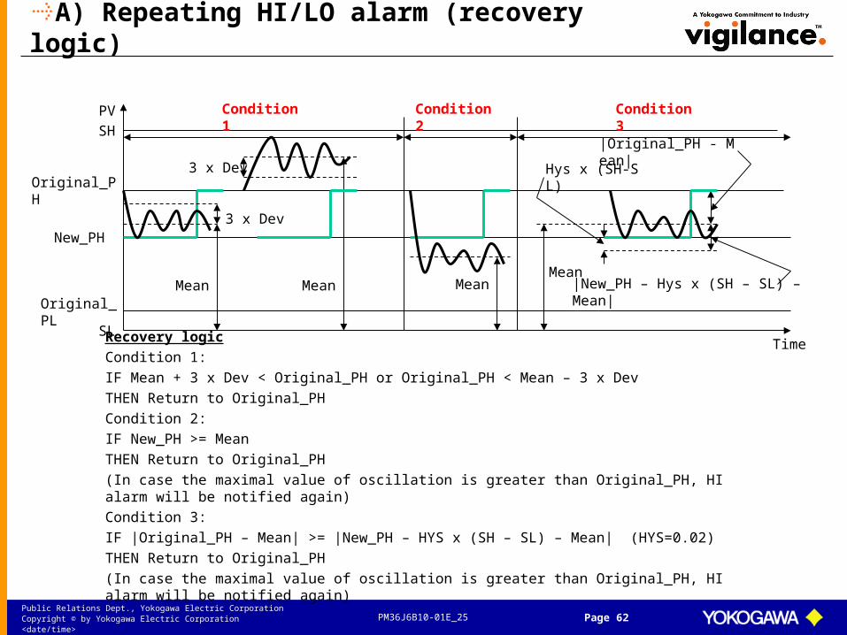
A) Repeating HI/LO alarm (recovery logic)
Recovery logic
Condition 1:
IF Mean + 3 x Dev < Original_PH or Original_PH < Mean – 3 x Dev
THEN Return to Original_PH
Condition 2:
IF New_PH >= Mean
THEN Return to Original_PH
(In case the maximal value of oscillation is greater than Original_PH, HI alarm will be notified again)
Condition 3:
IF |Original_PH – Mean| >= |New_PH – HYS x (SH – SL) – Mean| (HYS=0.02)
THEN Return to Original_PH
(In case the maximal value of oscillation is greater than Original_PH, HI alarm will be notified again)
SL
SH
Original_PH
Original_PL
New_PH
Time
PV
Mean Mean Mean
|Original_PH - Mean|
|New_PH – Hys x (SH – SL) – Mean|
Hys x (SH-SL)
3 x Dev
3 x Dev
Condition 1 Condition 2 Condition 3
Mean
PM36J6B10-01E_25Public Relations Dept., Yokogawa Electric CorporationCopyright © by Yokogawa Electric Corporation <date/time> Page 63
B) Long standing false alarm
Monitoring period
SL
SH
Original_PH
Start monitoring
New_PH
HYS x (SH - SL)
HI NR
Time
PV
Start
masking
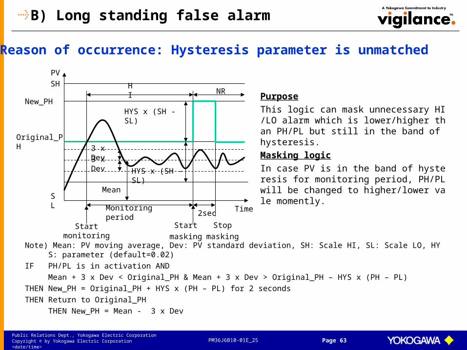
Purpose
This logic can mask unnecessary HI/LO alarm which is lower/higher than PH/PL but still in the band of hysteresis.
Masking logic
In case PV is in the band of hysteresis for monitoring period, PH/PL will be changed to higher/lower vale momently.
3 x Dev
Mean
HYS x (SH - SL)
3 x Dev
2sec
Reason of occurrence: Hysteresis parameter is unmatched
Note) Mean: PV moving average, Dev: PV standard deviation, SH: Scale HI, SL: Scale LO, HYS: parameter (default=0.02)
IF PH/PL is in activation AND
Mean + 3 x Dev < Original_PH & Mean + 3 x Dev > Original_PH – HYS x (PH – PL)
THEN New_PH = Original_PH + HYS x (PH – PL) for 2 seconds
THEN Return to Original_PH
THEN New_PH = Mean - 3 x Dev
Stop
masking

PM36J6B10-01E_25Public Relations Dept., Yokogawa Electric CorporationCopyright © by Yokogawa Electric Corporation <date/time> Page 64
C) Long standing true alarm
Monitoringperiod
IF HI/LO is activated for ordered period & Mean + 3 x Dev >= Original_PH
THEN New_PH/New_PL= SH/SL, 2 seconds later, Return to Original PH/PL
SL
SH
Original_PH
Start
monitoring
New_PH
HI NR
Time
PV
Re-notification
Purpose
This logic re-notifies longstanding true HI/LO alarm.
Re-notification logic
In case true HI/LO alarm is activated for monitoring period, PH/PL is changed momently to SH/SL, so that PH/PL is announced again.
HINR HI
Monitoringperiod
2Sec
Mean3 x Dev
HH
Reason of occurrence: Still function of CS3000 is not used

PM36J6B10-01E_25Public Relations Dept., Yokogawa Electric CorporationCopyright © by Yokogawa Electric Corporation <date/time> Page 65
D) Oscillation alarm
Monitoring period
SL
SH
PL
Start
monitoring
PH
Time
PV
Start
masking
Purpose
This logic masks unnecessary HI/LO alarms by setting AOF in case PV is oscillated due to the mismatch of PID parameters.
Masking Logic
In case HI/LO alarms are notified one after the other for ordered times, Exapilot sets AOF. (Select HH or HI, LO or LL)
Recovery Logic
In case HI/LO alarms are not notified for ordered period, Exapilot sets AON.
(In case PID is not retuned, HI/LO alarms
are continuously masked)
AOF
Monitoring period
1 2
AON AON
Occurrence number
Stop
masking
1 2
LL
HH
HI HI
LO LO
PID is retuned
Reason of occurrence: PID parameter is unmatched

PM36J6B10-01E_25Public Relations Dept., Yokogawa Electric CorporationCopyright © by Yokogawa Electric Corporation <date/time> Page 66
E) Repeating Annunciator message
Monitoring period
Start
monitoring
Purpose
This logic masks an unnecessary annunciator which announced repeatedly.
Masking logic
In case annunciator is announced ordered times in monitoring period, AOF is set to target annunciator (%AN). Then target tag is registered as habitual.
ON
%ANN
OFF
AON
Monitoringperiod
TimeMonitoringperiod
1 2 3
Occurrencenumber
Start
masking
Recovery logic
In case annunciator is not announced for monitoring period, AON is set to target annunciator (%AN).
Masking logic (After learning)
In case registered tag announced annunciator again, AOF is set without waiting.
Reason of occurrence: DCS sequence is not prepared
Stop
masking
AOF

PM36J6B10-01E_25Public Relations Dept., Yokogawa Electric CorporationCopyright © by Yokogawa Electric Corporation <date/time> Page 67
F) Fault diagnosis and suppression of IOP alarm
Monitoring period
SL
SH
Judgment
HI IOPRAW
Purpose
This logic detects true IOP/IOP- alarms which announced due to range over.
Detection Logic
In case IOP/IOP- is happened after HI/HH or LO/LL alarm is notified, and is recovered after ordered period, this logic shows the reason of IOP/IOP- alarm (range over). Also target tag is registered as habitual.
Exclude logic
In case registered tag announces IOP/IOP- alarm again, target tag is excluded from watch list.
HHNR HH
HH
PH
HI
IOP
Start
monitoringMonitoring periodfor IOP detection
Reason of occurrence: Range over (engineering problem)
PM36J6B10-01E_25Public Relations Dept., Yokogawa Electric CorporationCopyright © by Yokogawa Electric Corporation <date/time> Page 68
Startmonitoring
(0%)SL
(100%)SH
IOP IOPRAW
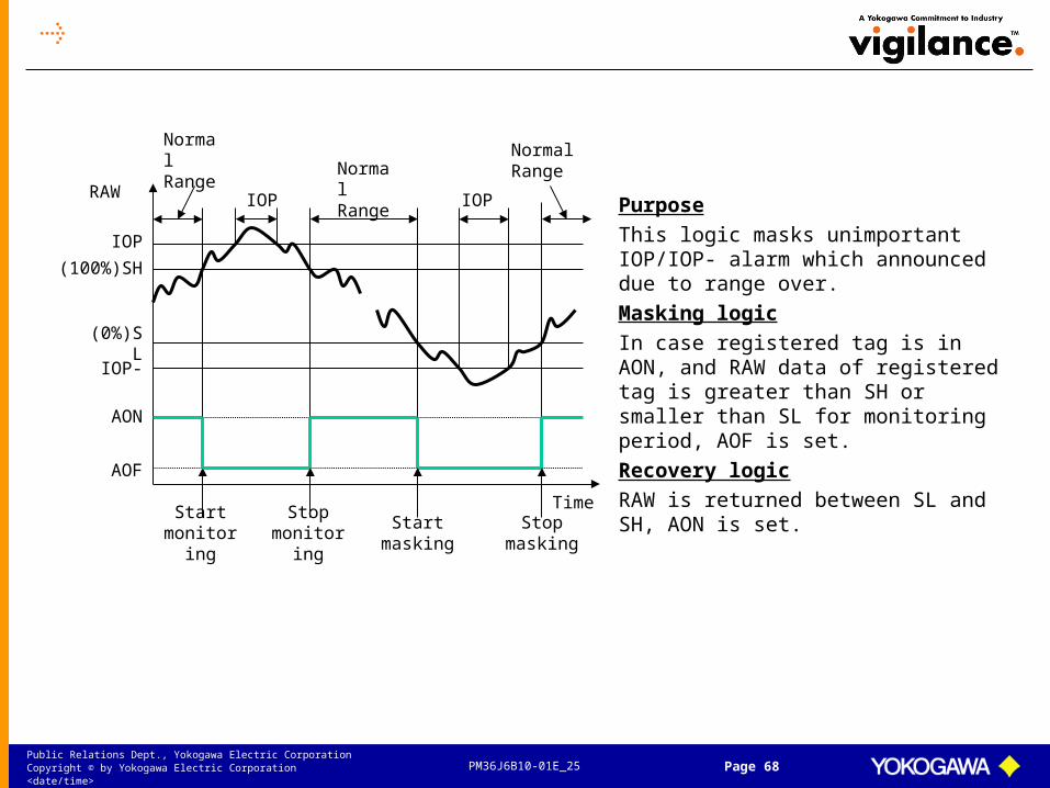
Purpose
This logic masks unimportant IOP/IOP- alarm which announced due to range over.
Masking logic
In case registered tag is in AON, and RAW data of registered tag is greater than SH or smaller than SL for monitoring period, AOF is set.
Recovery logic
RAW is returned between SL and SH, AON is set.
Normal Range
IOP-
IOP
Normal Range
Normal Range
Time
AON
Stopmonitoring
Startmasking
Stopmasking
AOF

PM36J6B10-01E_25Public Relations Dept., Yokogawa Electric CorporationCopyright © by Yokogawa Electric Corporation <date/time> Page 69
SL
IOP
Judgment 5Sec
IOPRAWPurpose
This logic detects true IOP/IOP- alarm which notified due to the failure of field transmitter.
Detection logic
In case IOP/IOP- is happened even though HI/HH or LO/LL alarm is not notified, or IOP/IOP- is happened immediately (within 5 seconds) after HI/HH or LO/LL alarm is notified, this logic shows the reason of IOP/IOP- alarm (failure of field transmitter). Also target tag is registered as habitual.
Masking logic
In case registered tag announces IOP/IOP- alarm again, AOF is set continuously.
NRNR NR
HH
PH
IOP
JudgmentStart
monitoringStart
monitoring
SH
Monitoringperiod
Monitoring period
HI
AON
Reason of occurrence: Failure of field transmitter
AOF
HH
PM36J6B10-01E_25Public Relations Dept., Yokogawa Electric CorporationCopyright © by Yokogawa Electric Corporation <date/time> Page 70
SL
SH
Judgment
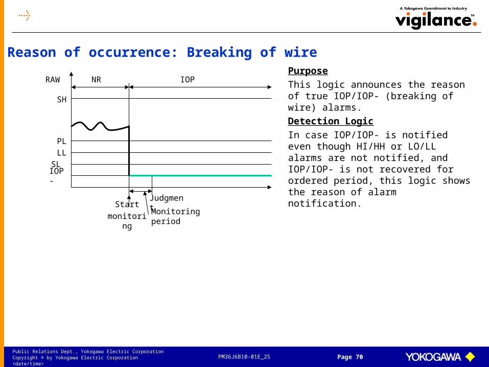
IOPRAWPurpose
This logic announces the reason of true IOP/IOP- (breaking of wire) alarms.
Detection Logic
In case IOP/IOP- is notified even though HI/HH or LO/LL alarms are not notified, and IOP/IOP- is not recovered for ordered period, this logic shows the reason of alarm notification.
NR
LL
PL
IOP-
Monitoring periodStart
monitoring
Reason of occurrence: Breaking of wire

PM36J6B10-01E_25Public Relations Dept., Yokogawa Electric CorporationCopyright © by Yokogawa Electric Corporation <date/time> Page 71
(2) Dynamic alarm setting
Alarm threshold (PH/PL) should be changed dynamically according to the drastic changes of set point (e.g. load change, grade change)
Exapilot Excel Link icon (option) reads optimum alarm threshold (PH/PL) to FCS automatically when SV is drastically changed
Exapilot Correlation Diagnosis icon (Advanced Alarm option) can monitor the correlation between elapsed time and process variable (PV) online
Start up Grade A Grade B
GradeChange
Shut down
PH=100
PL=80PH=SV + 5
PL=SV - 10
PH=SV + 10
PL=SV - 12
PH=200
PL=180 PH=SV + 4
PL=SV – 6
PH=SV + 4
PL=SV - 2 TIME
PV

PM36J6B10-01E_25Public Relations Dept., Yokogawa Electric CorporationCopyright © by Yokogawa Electric Corporation <date/time> Page 72
Case Branch icon
In case ofGrade A
Repetition
Out put toDCS icon
A B C D E
GRADE A Grade A Grade B Grade C Grade D

PM36J6B10-01E_25Public Relations Dept., Yokogawa Electric CorporationCopyright © by Yokogawa Electric Corporation <date/time> Page 73
For the transient condition
Correlation diagnosis icon

PM36J6B10-01E_25Public Relations Dept., Yokogawa Electric CorporationCopyright © by Yokogawa Electric Corporation <date/time> Page 74
(3) Addition of pre-alert
SL
SH
PL
Start
monitoring
PH
Time
PV
Start
monitoring
Purpose
This logic announces pre-process alert in case;
-PH/PL is announced
-PV is increasing/decreasing
-PV will reach HH/LL within ordered period (e.g. within 5 minutes)
HH LO
LL
HH
NR HI NR LL
NotifyHH pre-alert
NotifyLL pre- alert
Period of
notification
Period of
notification
Pre-alert function predicts an indication of HH/LL alarm before HH/LL is announced, and displays alert message to operators to prevent ESD.

PM36J6B10-01E_25Public Relations Dept., Yokogawa Electric CorporationCopyright © by Yokogawa Electric Corporation <date/time> Page 75
(4) Replacement to advanced alarm
Various kinds of diagnosis templates (Standard/Option)– Fault diagnosis
• Field transmitter (e.g. Failure, Breaking of wire)• Control valve (e.g. Sticking, Leakage, Clogging of strainer)• Pump (e.g. Trip)• Pipe (e.g. Clogging, Leakage)• Storage tank (e.g. Leakage)
– Overload monitor• Pump• Compressor• Turbine• Centrifuge• Blower• Agitator
– Operation efficiency monitor• Heat exchanger (e.g. Energy effectiveness)• Distillation tower (e.g. tray performance, Temp. distribution)• Reactor
– Quality monitorDetect an early sign of abnormality faster than it’s detected by DCS alarmsNotify the reason of alarm and adequate countermeasure to operatorsSend e-mail to relevant peopleExecute countermeasure automatically if necessary

PM36J6B10-01E_25Public Relations Dept., Yokogawa Electric CorporationCopyright © by Yokogawa Electric Corporation <date/time> Page 76
Standard logic templates
Monitoring Failure of Field Instrumentation– Detect Invariant Indicated Value (A01)– Detect Continuously Increasing Indicated Value (A02)– Detect Continuously Decreasing Indicated Value (A03)– Detect Deviation Alarm between 2-instruments (A04)– Detect Deviation Alarm between 3-instruments (A05)
Monitoring Process Abnormalities– Detect Hunting S Type (Standard deviation type) (B01)– Detect Hunting DS Type (Deviation of standard deviation) (B02)– Detect Deviation Alarm between Theoretical Value and Raw Value (B03)
Preventing Miss-operation– Detect Neglected Alarm (C01)– Detect Neglected MODE (C02)– Detect Neglected CAL (C03)
Monitoring Failure/Overload of Field Equipments– Monitoring Control Valve (EXA01)– Monitoring Pressure Gauge (EXA02)– Monitoring Reciprocating Compressor Abnormalities (EXA03)– Monitoring Clogging in Process Units (EXA04)
Monitoring Process Abnormalities– Monitoring Reactor Temperature Distribution (EXB01)– Monitoring Heat Balance Abnormality in the Furnace (EXB02)
PM36J6B10-01E_25Public Relations Dept., Yokogawa Electric CorporationCopyright © by Yokogawa Electric Corporation <date/time> Page 77
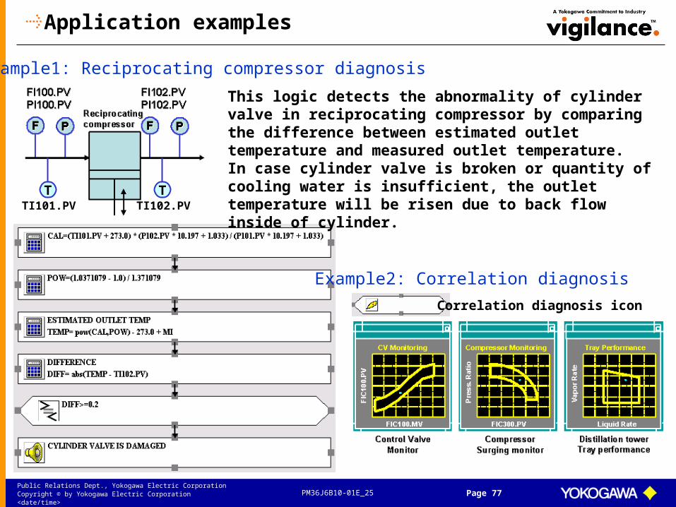
Application examples
This logic detects the abnormality of cylinder valve in reciprocating compressor by comparing the difference between estimated outlet temperature and measured outlet temperature.In case cylinder valve is broken or quantity of cooling water is insufficient, the outlet temperature will be risen due to back flow inside of cylinder.
Example1: Reciprocating compressor diagnosis
Example2: Correlation diagnosis
Correlation diagnosis icon
T TTI101.PV TI102.PV

PM36J6B10-01E_25Public Relations Dept., Yokogawa Electric CorporationCopyright © by Yokogawa Electric Corporation <date/time> Page 78
Exapilot can define pre-alert which can detect early sign of process abnormality before it is detected by process HI/LO alarms.
Example3: Reactor temperature distribution diagnosis
TI102.PH
TI102.PV1 hour
5 degrees

PM36J6B10-01E_25Public Relations Dept., Yokogawa Electric CorporationCopyright © by Yokogawa Electric Corporation <date/time> Page 79
P
P
PI101.PV
PI103.PV
PPI102.PV
Low pressure steam
(-0.1 MPa <= PI101.PV-P102.PV <= 0.1 MPa)
(-0.1 MPa <= PI101.PV-P103.PV <= 0.1 MPa)
Guidance message
Example4: Pressure indicator diagnosis This logic detects the abnormality of pressure indicator by checking the difference of three pressures.
Furnace
FI103.PV
FI101.PV
FI102.PV
TI100.PV
TI200.PVLowMaterial A
LowMaterial B
FuelGas
XI103.PV
Example5: Furnace incomplete combustion diagnosis
This logic detects early sign of incomplete combustion in furnace unit before DCS HI alarm detects it, by monitoring the difference between “Fuel gas calorie” calculated using fuel gas flow & gravity and “Furnace duty” calculated using flow & temperature of furnace unit.

PM36J6B10-01E_25Public Relations Dept., Yokogawa Electric CorporationCopyright © by Yokogawa Electric Corporation <date/time> Page 80
(5) Prevention of miss-operation
Incorrect action must be detected ASAP to prevent serious troubleExapilot Advanced Alarm can detect various kinds of miss-operation by monitoring operator’s behavior
Example: Miss of tag mode change
IF FIC100.MODE is changed to “MAN” 3 minutes lapsed FIC100.MODE is still in “MAN”THENExapilot changes tag mode to “AUT”

PM36J6B10-01E_25Public Relations Dept., Yokogawa Electric CorporationCopyright © by Yokogawa Electric Corporation <date/time> Page 81
3.4 Operator training system
PM36J6B10-01E_25Public Relations Dept., Yokogawa Electric CorporationCopyright © by Yokogawa Electric Corporation <date/time> Page 82
Training system
Use Exapilot and CS 3000 test function (WDA)No need to modify existing DCS applicationLow cost systemSimple process model can be made in Exapilot– Dead time– Time lag– Material balance, etc.
General training using HIS windowsTraining for transition operation using Exapilot window
PM36J6B10-01E_25Public Relations Dept., Yokogawa Electric CorporationCopyright © by Yokogawa Electric Corporation <date/time> Page 83
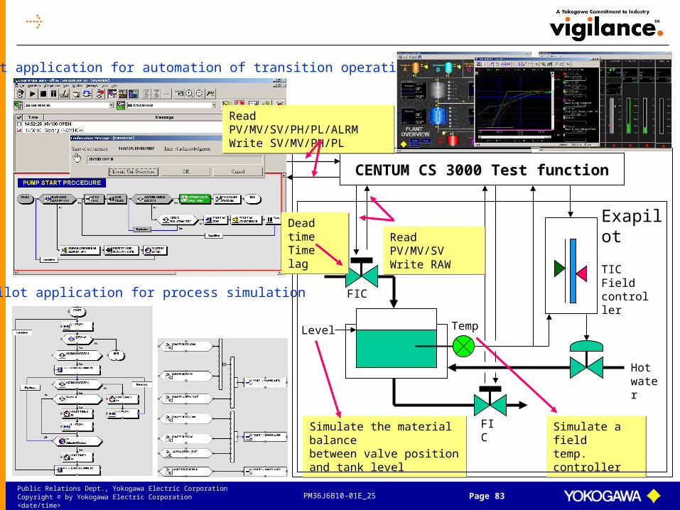
Simulate the material balancebetween valve positionand tank level
Simulate the material balancebetween valve positionand tank level
FIC
FIC
Level
TICFieldcontroller
Hot water
CENTUM CS 3000 Test function
Simulate a fieldtemp. controllerSimulate a fieldtemp. controller
Temp
ExapilotRead PV/MV/SVWrite RAWRead PV/MV/SVWrite RAW
Dead timeTime lagDead timeTime lag
Exapilot application for process simulation
Exapilot application for automation of transition operation
Read PV/MV/SV/PH/PL/ALRMWrite SV/MV/PH/PLRead PV/MV/SV/PH/PL/ALRMWrite SV/MV/PH/PL