Embed Size (px)
Citation preview
8th European LS-DYNA Users Conference, Strasbourg - May 2011
Ply-based composite modeling with the new *ELEMENT_SHELL_COMPOSITE keyword
Dr.-Ing. Ulrich Stelzmann Dr.-Ing. Matthias Hörmann
CADFEM GmbH, Grafing b. München, Germany
Summary
Because of their superior mechanical properties in combination with a relative low density Fiber Reinforced Composites (FRC) are of great potential in the area of lightweight structures respectively applications. Nevertheless usage and acceptance of FRC highly depends on the fact, whether or not it is possible to prescribe and predict their structural behavior using the Finite Element Method. LS-DYNA has a great potential to simulate the behavior of composite structures since many years. But the model generation of complex layered structures with many different plies in different directions may become very expensive. Starting with LS971 Revision R5.1 LS-DYNA offers the new keyword *ELEMENT_SHELL_COMPOSITE, which is a generalization of the already known *PART_COMPOSITE. This new keyword allows a very comfortable description of composite layers using a ply-based concept. Within one part elements may have different number of through thickness integration points as well as different material angles in each layer. Because of that the model must not be split up in many parts, which makes pre- and also postprocessing much more practical. The ANSYS Composite PrepPost enables a comfortable way to generate layered composite structures using a ply-cased = manufacturing-based concept and export these data to LS-DYNA in the new format. It offers a common composite definition for both ANSYS and LS-DYNA simulations. 1 Introduction to Composites Since beginning of 20.th century there are serious efforts to investigate and to use the large potential, which results from the use of new composite materials. From the technical production of high-quality fibers as well as from the development of new production techniques various application possibilities for fiber reinforced composite materials resulted. In most of these application areas beside the weight reduction, the high specific stiffness and strength are exploited and used. Composite materials are made of at least two distinct materials with different material parameters for each phase. Fiber reinforced composites (FRC) are composites where one material component (fiber) is used as a reinforcing material for the matrix. Particle reinforced composites consist of particles of one material dispersed in a matrix of a second material. Particles may have any shape or size, but are generally spherical, ellipsoidal, polyhedral, or irregular in shape. In the current article we will restrict ourselves to long-fiber reinforced composite laminates even though there are numerical solutions for short-fiber reinforced composites like LS-DYNA and Digimat available. Long-fiber reinforced laminates used in real structure are featuring several challenges to the user: typically there is a huge number of plies in a large structure to handle. Additionally, plies are only located in those regions where they are absolutely needed for deformation, stiffness and strength. Transition between those regions is done using an extensive tapering of plies, i.e. a gradual change of number of plies through the thickness. The latter results in a numerical model where the number of thickness integration points changes throughout the structure even though it is one body or in LS-DYNA language one PART. An additional need results from the fiber or ply placement onto curved structures. Because of the curved natures of the structure a reorientation of the fibers occurs, which needs to be accounted for a proper representation of stiffness and strength. Draping simulation is the keyword for those kinds of predictions. Unfortunately, this leads to a relative fiber angle change in the laminate from element to element. Consequently an efficient preprocessing tool is needed to calculate those corrections.
8th European LS-DYNA Users Conference, Strasbourg - May 2011
Additionally LS-DYNA solver functionality needs to be expanded such that a stacking sequence per element can be introduced. 2 Modeling of layered composites with shell element s – Status Old way: *INTEGRATION_SHELL Current way: *PART_COMPOSITE New way: *ELEMENT_SHELL_COMPOSITE Modeling of layered composites with shell elements has a long history in LS-DYNA. Twenty years ago it was done by the use of *INTEGRATION_SHELL, a user defined thickness integration, with the input of relative thickness coordinates and weighting factors.
Starting with LS971 in 2006 the keyword *PART_COMPOSITE enables a simplified method for defining composite layups. No *SECTION and no *INTEGRATION_SHELL is needed. The *PART_COMPOSITE only refers to *MAT definitions for different material data, together with the thickness of the layer and a material angle, relative to the material direction of the element.
8th European LS-DYNA Users Conference, Strasbourg - May 2011
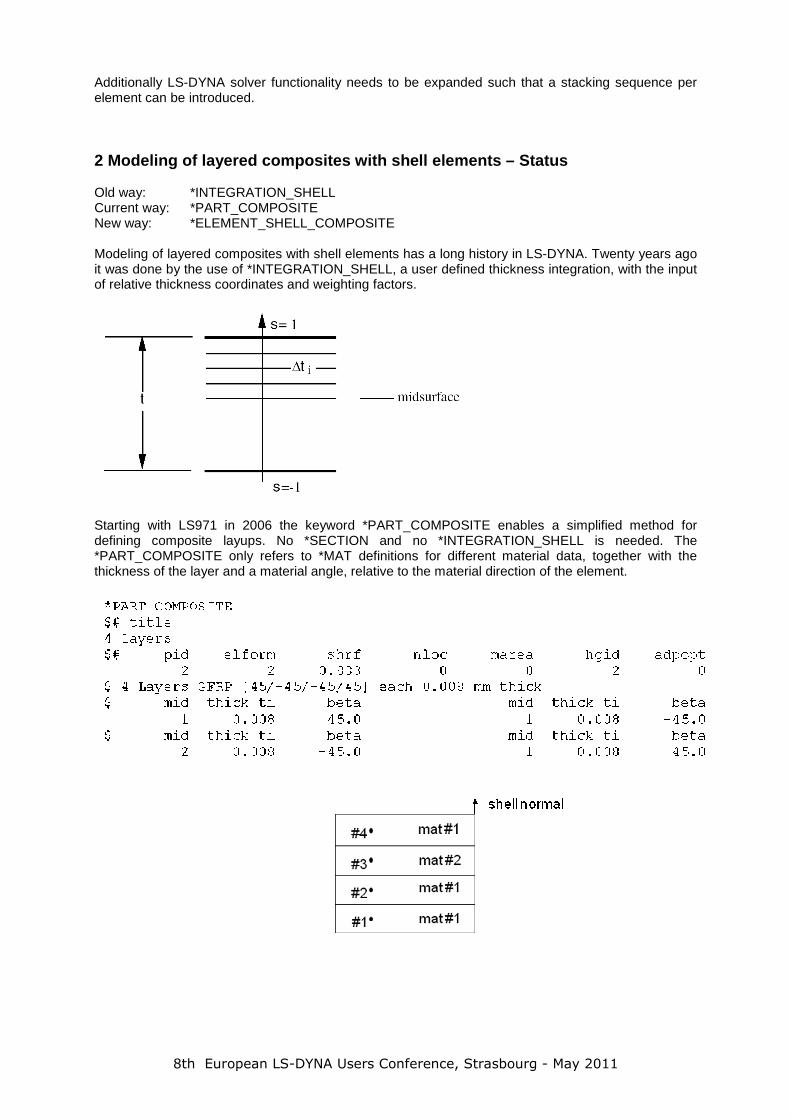
In each case the elements need to have own material directions, may be other than the local element coordinate system. Orthotropic or anisotropic material models manage this with the parameter AOPT:
For simple geometries the fiber direction may be easily defined by setting of a suitable AOPT value. But for complex structures with free-form surfaces the fiber direction may be curved over the surface. The keyword *ELEMENT_SHELL_BETA can be used to define arbitrary material direction on each single element. This is still a powerful tool, but don’t fulfill real composite needs, because of each layer in a composite structure may have arbitrary curved fiber orientation, so only one material direction per element is not enough. The BETA angle in *PART_COMPOSITE describes the material direction for each layer separately, but it is constant for the whole part.
8th European LS-DYNA Users Conference, Strasbourg - May 2011
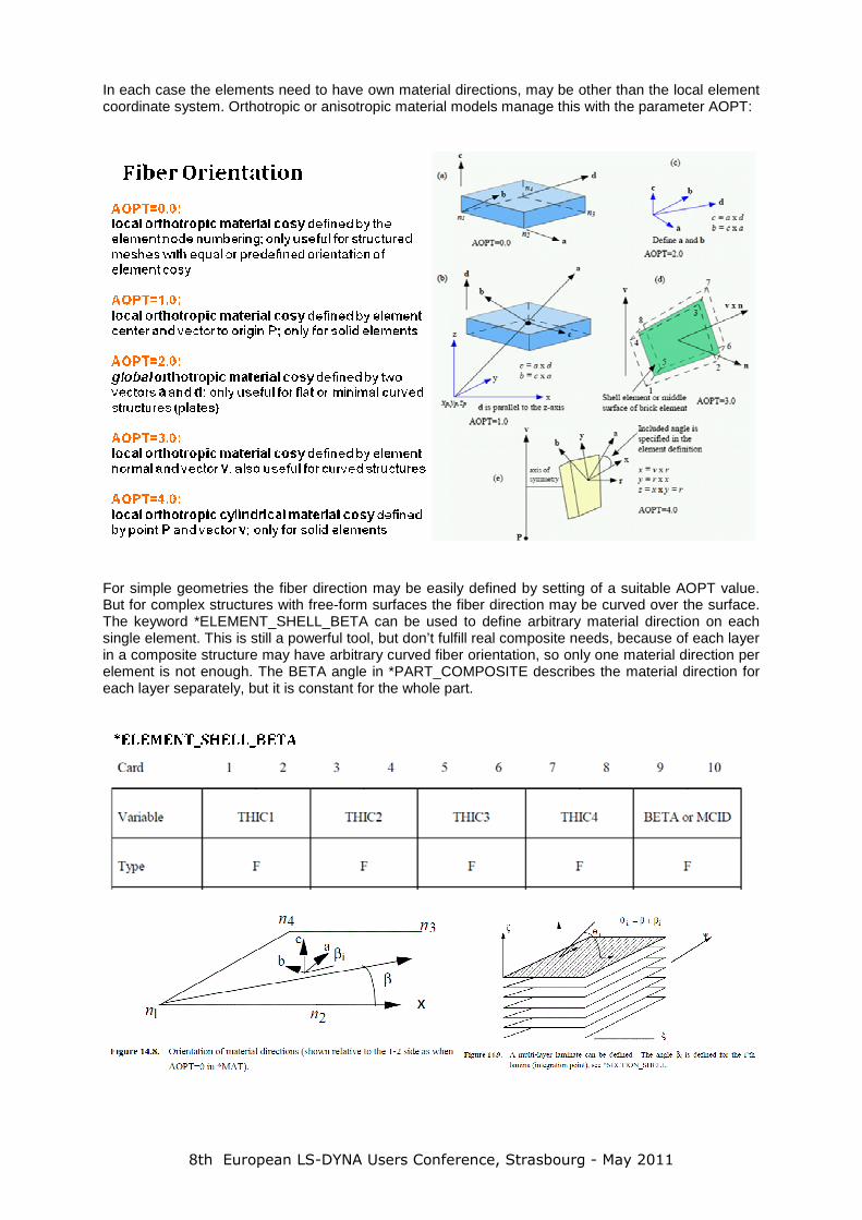
3 True Composite Needs: Zone-based vs. ply-based mo deling concept True composite parts may have features which are hard to describe with the current input structure:
• material plies start and end at any location • several hundreds of zones � number of plies across shell thickness will vary • any changes in laminate stacking sequence or ply sizes requires rework of zones
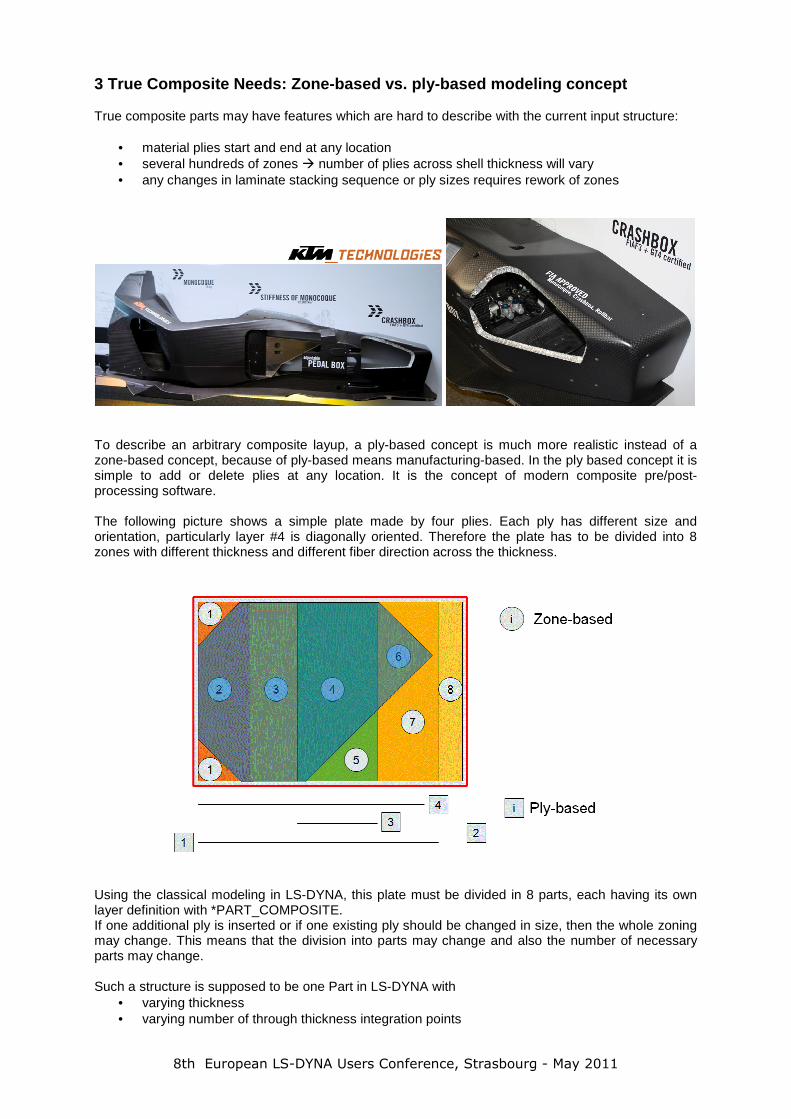
To describe an arbitrary composite layup, a ply-based concept is much more realistic instead of a zone-based concept, because of ply-based means manufacturing-based. In the ply based concept it is simple to add or delete plies at any location. It is the concept of modern composite pre/post-processing software. The following picture shows a simple plate made by four plies. Each ply has different size and orientation, particularly layer #4 is diagonally oriented. Therefore the plate has to be divided into 8 zones with different thickness and different fiber direction across the thickness.
Using the classical modeling in LS-DYNA, this plate must be divided in 8 parts, each having its own layer definition with *PART_COMPOSITE. If one additional ply is inserted or if one existing ply should be changed in size, then the whole zoning may change. This means that the division into parts may change and also the number of necessary parts may change. Such a structure is supposed to be one Part in LS-DYNA with
• varying thickness • varying number of through thickness integration points

8th European LS-DYNA Users Conference, Strasbourg - May 2011
Draping adds additional needs. Before draping, relative angle between plies is the same in all regions. After draping, relative angle between plies is only the same if draping seed point and direction are identical, reorientation from element to element with *ELEMENT_SHELL_BETA may be necessary. But for arbitrary draping relative angle will vary from region to region or from element to element.
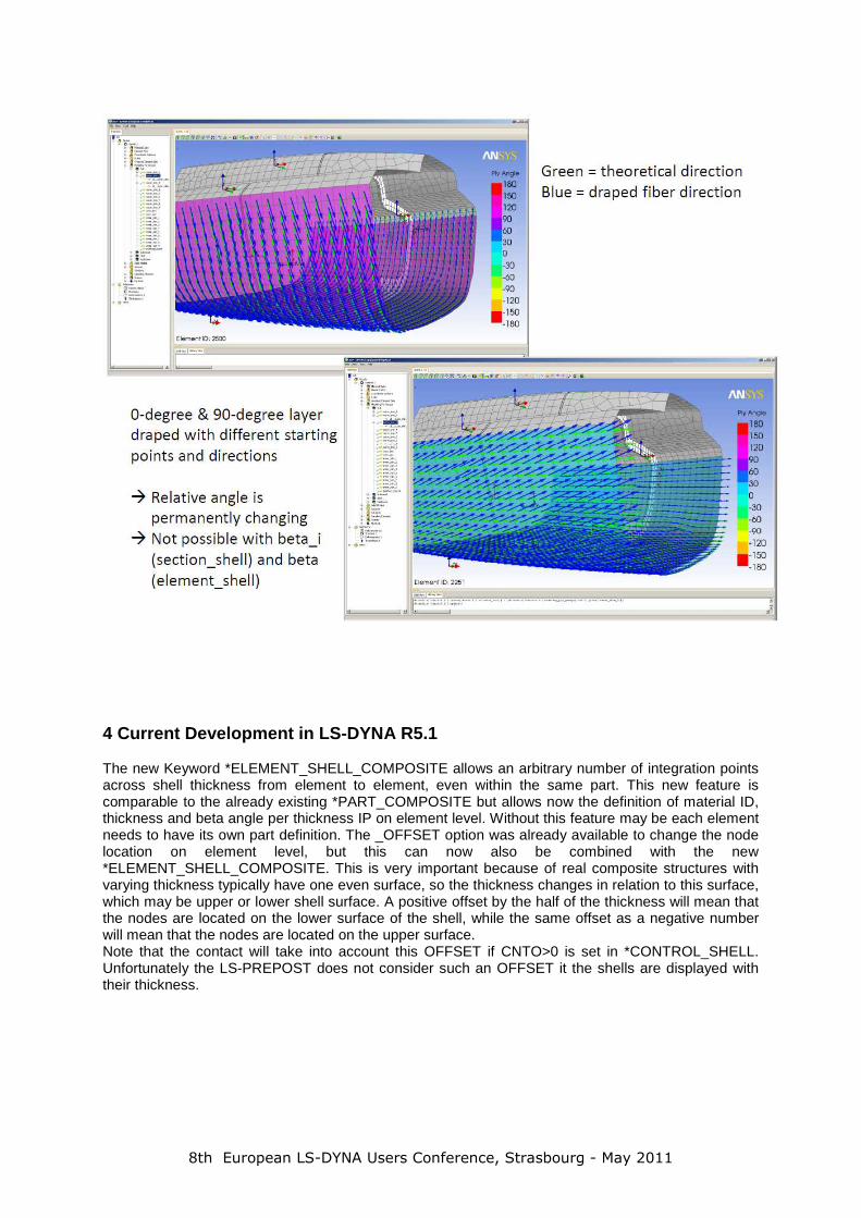
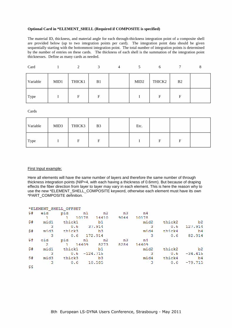
The next two pictures are showing a situation where 0-degree and 90-degree layers are drapped with the same starting point and direction. Therefore the relative angle between the layers is still 90 degrees. This can be modeled with the existing *ELEMENT_SHELL_BETA.
In the next two pictures the 0-degree and 90-degree layers are draped with different starting points and direction. Therefore the relative angle between the layers is permanently changing from element to element. This can’t be modeled with the existing *ELEMENT_SHELL_BETA.
8th European LS-DYNA Users Conference, Strasbourg - May 2011
4 Current Development in LS-DYNA R5.1 The new Keyword *ELEMENT_SHELL_COMPOSITE allows an arbitrary number of integration points across shell thickness from element to element, even within the same part. This new feature is comparable to the already existing *PART_COMPOSITE but allows now the definition of material ID, thickness and beta angle per thickness IP on element level. Without this feature may be each element needs to have its own part definition. The _OFFSET option was already available to change the node location on element level, but this can now also be combined with the new *ELEMENT_SHELL_COMPOSITE. This is very important because of real composite structures with varying thickness typically have one even surface, so the thickness changes in relation to this surface, which may be upper or lower shell surface. A positive offset by the half of the thickness will mean that the nodes are located on the lower surface of the shell, while the same offset as a negative number will mean that the nodes are located on the upper surface. Note that the contact will take into account this OFFSET if CNTO>0 is set in *CONTROL_SHELL. Unfortunately the LS-PREPOST does not consider such an OFFSET it the shells are displayed with their thickness.
8th European LS-DYNA Users Conference, Strasbourg - May 2011
Optional Card in *ELEMENT_SHELL (Required if COMPOSITE is specified) The material ID, thickness, and material angle for each through-thickness integration point of a composite shell are provided below (up to two integration points per card). The integration point data should be given sequentially starting with the bottommost integration point. The total number of integration points is determined by the number of entries on these cards. The thickness of each shell is the summation of the integration point thicknesses. Define as many cards as needed.
Card
1 2 3 4 5 6 7 8
Variable MID1 THICK1 B1 MID2 THICK2 B2
Type I F F I F F
Cards
Variable MID3 THICK3 B3 Etc.
Type I F F I F F
First Input example: Here all elements will have the same number of layers and therefore the same number of through thickness integration points (NIP=4, with each having a thickness of 0.6mm). But because of draping effects the fiber direction from layer to layer may vary in each element. This is here the reason why to use the new *ELEMENT_SHELL_COMPOSITE keyword, otherwise each element must have its own *PART_COMPOSITE definition.
8th European LS-DYNA Users Conference, Strasbourg - May 2011
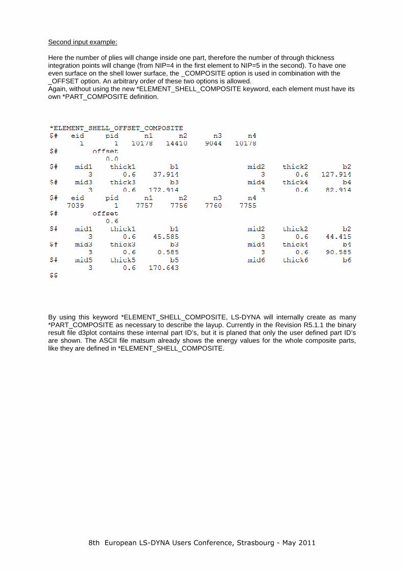
Second input example: Here the number of plies will change inside one part, therefore the number of through thickness integration points will change (from NIP=4 in the first element to NIP=5 in the second). To have one even surface on the shell lower surface, the _COMPOSITE option is used in combination with the _OFFSET option. An arbitrary order of these two options is allowed. Again, without using the new *ELEMENT_SHELL_COMPOSITE keyword, each element must have its own *PART_COMPOSITE definition.
By using this keyword *ELEMENT_SHELL_COMPOSITE, LS-DYNA will internally create as many *PART_COMPOSITE as necessary to describe the layup. Currently in the Revision R5.1.1 the binary result file d3plot contains these internal part ID’s, but it is planed that only the user defined part ID’s are shown. The ASCII file matsum already shows the energy values for the whole composite parts, like they are defined in *ELEMENT_SHELL_COMPOSITE.
8th European LS-DYNA Users Conference, Strasbourg - May 2011
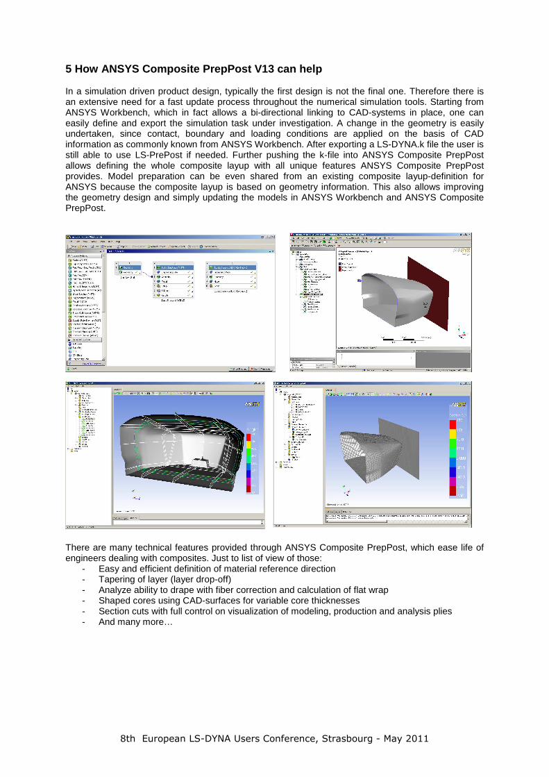
5 How ANSYS Composite PrepPost V13 can help In a simulation driven product design, typically the first design is not the final one. Therefore there is an extensive need for a fast update process throughout the numerical simulation tools. Starting from ANSYS Workbench, which in fact allows a bi-directional linking to CAD-systems in place, one can easily define and export the simulation task under investigation. A change in the geometry is easily undertaken, since contact, boundary and loading conditions are applied on the basis of CAD information as commonly known from ANSYS Workbench. After exporting a LS-DYNA.k file the user is still able to use LS-PrePost if needed. Further pushing the k-file into ANSYS Composite PrepPost allows defining the whole composite layup with all unique features ANSYS Composite PrepPost provides. Model preparation can be even shared from an existing composite layup-definition for ANSYS because the composite layup is based on geometry information. This also allows improving the geometry design and simply updating the models in ANSYS Workbench and ANSYS Composite PrepPost.
There are many technical features provided through ANSYS Composite PrepPost, which ease life of engineers dealing with composites. Just to list of view of those:
- Easy and efficient definition of material reference direction - Tapering of layer (layer drop-off) - Analyze ability to drape with fiber correction and calculation of flat wrap - Shaped cores using CAD-surfaces for variable core thicknesses - Section cuts with full control on visualization of modeling, production and analysis plies - And many more…