Embed Size (px)
Citation preview


Plumbing Systems 22 00 01 - 1 ADG15374B – STAR Campaign FY16 – Pasadena Readiness Center Major Maintenance
22 00 01 PLUMBING SYSTEMS
1.00 GENERAL
1.01 WORK INCLUDED
A. Provide labor, materials, equipment and incidentals for complete, operable plumbing systems. Provide appurtenances for every pipe, valve, and fixture or equipment item for a complete operable system.
1.02 QUALITY ASSURANCE
A. Verify location, size, depth and pressure of each utility prior to beginning Work. If conditions are found that will adversely affect the installation, notify the Owners Representative in writing before proceeding with Work.
B. Plumbing fixtures and trim of like kind shall be of the same manufacturer throughout the Project, in the following categories:
1. Water closets, lavatories, urinals, bathtubs.
2. Showers, and shower-tub combinations.
3. Countertop sinks.
4. Drinking Fountains and Electric water coolers.
5. Emergency shower, eye and face washes.
6. Faucets, mixing valves (other than thermostatic mixing valves).
7. Tailpiece, fixture traps, escutcheons, arm extensions, strainers.
8. Fixture carriers.
C. Comply with requirements of utility company supplying the water including backflow prevention.
1.03 WATER USAGE REQUIREMENTS
A. Water saving performance standards of the Texas Commission on Environmental Quality (TCEQ) adopted April 26, 2012, shall apply to every fixture included for this Project.
1. The maximum flow from a sink or lavatory faucet shall not exceed 2.20 gallons of water per minute at 60 psig.
2. The maximum flow from a shower head shall not exceed 2.5 gallons of water per minute at 80 psig.
3. The maximum volume of water per flush from a urinal and associated flush valve shall not exceed 0.5 gallons of water per flush.
4. The maximum volume of water per flush from a toilet (water closet) shall not exceed 1.60 gallons (1.6 gpf)

Plumbing Systems 22 00 01 - 2 ADG15374B – STAR Campaign FY16 – Pasadena Readiness Center Major Maintenance
2.00 SUBMITTALS
A. Provide Submittals in accordance with Section 01 33 00 “Submittal Procedures” and include manufacturer’s Product Data sheets for the following:
1. Plumbing fixtures and trim.
2. Piping materials and valves.
3. Equipment and accessories.
B. Operation and Maintenance Data: Submit operation and maintenance data in accordance with Division 01.
C. LEED Submittal:
1. Product Data for all applicable credits in the Water Efficiency (WE), category. Documentation indicating flow and water consumption requirements.
2. Product Data for Environmental Quality (EQ), category: For solvent cements and adhesive primers, including printed statement of VOC content.
3. Product Data for all applicable Prerequisites.
2.02 STANDARDS
A. Authority Having Jurisdiction: Perform all Work in accordance with the regulations and ordinances of federal, state, and local agencies, who have lawful jurisdiction over the Place of Record. Notify proper authorities for inspections as Work progresses.
B. Codes and Ordinances: The design and installation shall be in accordance with the applicable provisions of the latest edition of the following codes and ordinances. These codes and ordinances shall apply as if written here in their entirety:
1. Uniform Plumbing Code (UPC) 2006, with any local city amendments.
2. International Energy Conservation Code (IECC) 2009, with any local city amendments.
3. Occupational Safety and Health Standards (OSHA).
4. Texas Water Commission; Texas Water Conservation Standards.
5. Architectural Barriers Act (ABA) Standards 2015.
6. UFC-3-420-01 Plumbing Systems.
7. UFC 4-010-01 DOD Minimum Antiterrorism Standards for Buildings.
8. UFC 1-200-02 High Performance and Sustainable Building Requirements.
9. Army National Guard DG 415-5 General Facilities Information Design Guide.
C. Standards:
1. The design and installation shall be in accordance with the applicable provisions of the following standards. These standards shall apply as if written here in their entirety:
a. American National Standards Institute (ANSI)/ American Society of Mechanical Engineers (ASME).

Plumbing Systems 22 00 01 - 3 ADG15374B – STAR Campaign FY16 – Pasadena Readiness Center Major Maintenance
b. American National Standards Institute (ANSI)/ American Society for Testing Materials (ASTM).
c. American National Standards Institute (ANSI)/ American Welding Society (AWS).
d. American National Standards Institute (ANSI)/ American Water Works Association (AWWA).
e. American National Standards Institute (ANSI)/ National Fire Protection Association (NFPA).
f. American Society of Testing and Materials (ASTM) Publications.
g. American Welding Society (AWS) Specifications.
h. American Water Works Administration (AWWA) Publications.
i. American Society of Sanitary Engineering (ASSE).
j. Cast Iron Soil Pipe Institute (CIPE) Standards.
k. Texas Commission on Environmental Quality (TCEQ).
2.03 DELIVERY AND STORAGE
A. Deliver and store equipment and materials in accordance with Division 01. Handle pipe in a manner which prevents damage. Store on raised platforms or wood runners in neat piles. Prevent debris or dirt from entering open ends of pipe.
2.04 JOB CONDITIONS
A. Drawings are schematic and intended to show the general arrangement and extent of the Work. Follow dimensions without regard to scale. Determine the exact location and arrangement of piping with regard to the actual equipment furnished, the surrounding conditions and the work installed by other trades.
B. Review the Drawings and each Section of the Specifications. Install Work indicated, regardless of which Drawing or Section of the Specifications it occurs. No allowances shall be made for the Contractor’s failure to review complete Contract Documents.
C. Locate by field measurement the exact rough-in and final connection location of all fixtures, drains and plumbing. Center pipe between walls and chases.
D. Conform to the manufacturer’s rough-in and installation requirements for each fixture equipment and appliance.
E. Perform cutting and patching required to install the Work under the requirements of the individual trade. Patching shall restore the area to the original condition. No structural member shall be cut without the written approval of the Engineer.
F. Schedule Work to avoid conflicts with other trades.
G. For pipe penetrations through metal roofs, conform to the metal roofing manufacturer’s installation requirements.

Plumbing Systems 22 00 01 - 4 ADG15374B – STAR Campaign FY16 – Pasadena Readiness Center Major Maintenance
2.05 GUARANTEES
A. In addition to the Contractor’s standard 1 year guarantee, provide the manufacturer’s warranty for all equipment installed. Include warranties in the O & M Manual, in accordance with Division 01.
3.00 PRODUCTS
3.01 PIPE AND FITTINGS
A. Water Piping Buried Within 5 Feet of Building:
1. Copper Tubing: For 2-inch diameter and less, (ASTM B88), Type L or K or annealed. Fittings: ANSI/ASME B16.18, cast copper or ANSI/ASME B16.22, wrought copper. Joints: AWS A5.8 BCuP silver braze.
2. Copper Tube for 2-1/2-inch Diameter and Greater: (ASTM B88) Type L or K hard drawn. Fittings ANSI/ASME B16.8 cast copper or ANSI/ASME B16.22 wrought copper. Joints: AWS A5.8 BCuP silver braze.
3. Ductile Iron Piping for 3-inch Diameter and Greater: Pipe: ANSI/AWWA C151, Class 50. Fittings: ANSI/AWWA C110, ductile iron, standard thickness. Joints: ANSI/AWWA C111, rubber gasket, mechanical joint. Pipe and fittings shall have tar coated outside and cement mortar lined inside in accordance with ANSI A21.4.
B. Water Piping Above Grade:
1. Copper Tubing: For 4-inch diameter and less, (ASTM B88), Type L or K, hard drawn. Fittings: ANSI/ASME B16.18, cast brass, or ANSI/ASME B16.22, wrought copper. Joints: (ANSI/ASTM B32), solder, (Grade 95TA) or Copper Pipe 2 through 6 inches may be installed using mechanical type couplings on roll-grooved pipe; coupling housing, ductile iron (ASTM A536) grade 65-45-12, with factory coat copper alkyd enamel paint. Gaskets, flanges, shall be rated for the system by the manufacturer.
C. Sanitary Drain, Sanitary Waste and Vent Piping (DWV) Buried:
1. Cast Iron Pipe: (ASTM A74) service weight. Fittings: Cast iron. All cast iron soil pipe and fittings shall be marked with the collective trademark of the Cast Iron Soil Pipe Institute and be listed by NSF International. Joints: Hub-and-spigot, CISPI HSN compression type with (ASTM C564) neoprene gaskets.
D. Sanitary Drain, Sanitary Waste and Vent Piping (DWV) Above Grade:
1. Cast Iron Pipe: (ASTM A74), service weight. Fittings: Cast iron. Joints: Hub-and-spigot, CISPI HSN compression type with (ASTM C564) neoprene gaskets.
2. Cast Iron Pipe: (CISPI 301), hubless, service weight. Fittings: Cast iron. All cast iron pipe and fittings shall be marked with the collective trademark of the Cast Iron Soil Pipe Institute and shall be listed by NSF International. Joints: Cast-iron couplings (ASTM A48, Class 30-A) with neoprene gaskets (ASTM C1277, ASTM D412 18-8 and CISPI 310) stainless steel bolts and nuts; manufactured by MG Piping Products Co. or equal.
Plumbing Systems 22 00 01 - 5 ADG15374B – STAR Campaign FY16 – Pasadena Readiness Center Major Maintenance
E. Natural Gas Piping:
1. Natural Gas Piping, Buried:
a. Polyethylene Piping (for below ground use only): Pipe: ASTM D1248 and ASTM D2513, 75 psi rated working pressure. Fittings: PE fittings, ASTM D1248 and ASTM D2513, SDR 11, 50 psi rated working pressure. Joints: Butt fusion, in accordance with manufacturer’s recommendations and the Department of Transportation Title 49 of Federal Specifications, as it applies to heat fusion.
2. Natural Gas Piping, Above Grade:
a. Steel Pipe: ASTM A53, Schedule 40 black. Fittings: ANSI/ASME B16.3, malleable iron, or ASTM A234, forged steel welding type. Joints: Screwed for pipe 2 inches and under; ANSI/AWS D1.1, welded, for pipe over 2 inches.
3.02 FLANGES, UNIONS, AND COUPLINGS
A. Pipe size 2 inches and under: 150 psig malleable iron unions for threaded ferrous piping; bronze unions for copper pipe, solder joints.
B. Pipe size over 2 inches: 150 psig forged steel slip-on flanges for ferrous piping; bronze flanges for copper piping.
C. Dielectric Connections: Union with galvanized or plated steel threaded end, copper solder end, water impervious isolation barrier.
D. Gas Service Line Risers: PE pipe with coated, anodeless, steel pipe casing on riser section. Include inlet for heat-fusion connection to PE pipe and outlet for connection to shutoff valve.
3.03 NATURAL GAS METERS AND REGULATORS
A. Gas Service Sub-Meters:
1. Smart Sub-Meters: Sensus or approved equal AGA/IAS-listed natural gas meter including commercial grade pulsmatic transmitter and counter. Provide interface interlocks with IP server as designated by the government representative. Provide a metering transmitting recording smart meter system including all required appurtenances, devices, fittings for a complete, operable system. Acceptable manufacturer and Model: Sensus Sonix 880; or owner approved equal.
B. Service Regulators:
1. Service Regulators: AGA/IAS-listed for service regulators, single stage, steel jacketed, and corrosion resistant. Include atmospheric vent, elevation compensator, with threaded ends for NPS 2 and smaller, and flanged ends for NPS 2-1/2 and larger. Acceptable manufacturers: American Meter Co.; Equimeter, Inc.; Fisher Controls International, Inc.; National Meter; Schlumberger Industries, Gas Div.
2. Regulator Vents: Factory-installed or field-installed, corrosion-resistant screen in opening.

Plumbing Systems 22 00 01 - 6 ADG15374B – STAR Campaign FY16 – Pasadena Readiness Center Major Maintenance
3.04 VALVES (WITHIN 5 FEET OF BUILDING)
A. Ball Valves (For Water Shut-Off and Throttling):
1. Ball Valves 2 inches and Less: Full-port, rated 175-lb. minimum water, oil, air and gas pressure, brass or bronze construction, seat material as recommended by manufacturer for material conveying, lever handle, threaded or soldered connections. Throttling valves shall be provided with memory stops. Acceptable manufacturers and models: Crane, 9302, 9322; ITT Grinnell, 3500, 3500SJ; Milwaukee, BA-200, BA-250; Watts, B-6000, B-6001 and Nibco, T-580, S-580.
2. Ball Valves 2-1/2 inches and Greater: Full-port, rated 150-lb. minimum water, oil, air and gas pressure, bronze or carbon steel construction, seat material as recommended by manufacturer for material conveying, lever handle, flanged connections. Throttling valves shall be provided with memory stops. Acceptable manufacturers and models: Watts, G-4000M1; Crane, 941-TF; Apollo, 88-100 and Jamesbury, D150F.
B. Check Valves (Swing Check Valves):
1. Check valves 2 inches and Less: MSS SP-80 rated 175-lb. minimum water and air
pressure, brass or bronze construction, bronze disc, threaded or soldered connections.
Acceptable manufacturers and models: Watts, B-5000 & B-5001; Nibco, T-413-B & S-
413-B; Milwaukee, 509-1509; Crane, 37/1707 & 1707S.
2. Check Valves 2-1/2 inches and Greater: MSS SP-71 rated 150-lb. minimum water and air pressure, iron body, brass mounted, flanged connections. Acceptable manufacturers and models: Crane, 373; Nibco, F-918; Milwaukee, F-2974; ITT and Grinnell 6300A; Watts, F-511.
C. Valves (For Gas Piping Only):
1. Non-lubricated, Tapered Plug Valves (for 2 inches and Smaller): Brass or cast-iron body, with brass tapered plug; lever operation; and complying with ASME B16.33, MSS SP-78, UL 842, or AGA/IAS listing. Include lever. Include locking device. Acceptable manufacturers: Essex Brass Corp.; Grinnell Corp.-Mueller Co.-Gas Products Div.; Lyall, R.W. & Co., Inc.; McDonald, A.Y. Mfg. Co.
3.05 DOMESTIC WATER HEATERS AND ACCESSORIES
A. Electric Water Heaters (Direct Fired):
1. Domestic Water Heater (EWH1): Point-of-use instantaneous electric, UL listed, for wall mounted installation near or under fixture. Factory set water heater at 105 F or provide a high temperature shut-off, set at 105 F. Provide a flow restrictor, installed in the hot water outlet of the heater, compatible with the manufacturer’s recommendations and with the fixture selection.
a. Acceptable Manufacturers and Models:
1). EEMAX: “EX” Thermostatic Series.
2). Rheem.

Plumbing Systems 22 00 01 - 7 ADG15374B – STAR Campaign FY16 – Pasadena Readiness Center Major Maintenance
B. Gas Water Heaters (Direct Fired).
1. Domestic Water Heater (GWH1-2): ASHRAE 90.1-2013 energy efficient, gas-fired, tankless, condensing, wall mounted. Water heater air intake and exhaust gas vent shall be Schedule 40 PVC. Water heater shall be controlled by an internal circuit board that monitors the inlet and outlet temperatures with installed thermistors, sensing and controlling flow rate to set point temperature with air-fuel ratio controls in order to maintain thermal combustion efficiency. Units shall include safety features such as flame sensor system, high limit sensors, overheat prevention device, freeze protection mode, and fan rotation detector. Manifolded units shall be installed by connecting the units using cable-only connections. Set outlet temperature to 127°F maximum. The Contractor shall extend vent piping to the outside of the building in accordance with manufacturers instructions.
a. Acceptable Manufacturers and Models:
1). Navien NPE-240S- NG, or owner approved equal.
C. WATER HEATING SYSTEM ACCESSORIES
1. Circulation Pumps: Inline type, flanged connections, rated for 125 psi at 220 F, single stage, vertical split case, all bronze or stainless steel and provided with oil cups. See Schedule for capacity. Acceptable manufacturers: Bell & Gossett PL-30, or approved equal, 1/12 HP. 115V 1 phase, 7 gpm at 20 ft hd.
2. Thermostatic Control for Circulation Pumps: Heavy-duty snap-acting SPDT switch, copper constructed liquid filled capillary and bulb sensing element, 100 to 210 F set-point adjustment range, 5 to 15 F adjustable differential, 120 VAC, UL listed. One 0-10V (Analog): Speed Control by external controller. One 4-20mA (Analog): Connection with an external pressure sensor for the pressure control mode (two different pressure sensor ranges: 0-15 PSI and 0-30 PSI) l One external temperature sensor input for Differential Temp operating mode. Sensor Type KTY38 PN:104502 l One built-in temperature sensor for Set Point Temp and Differential-Temp operating mode. REMOTE BUILDING MANAGEMENT SYSTEM: The pump shall be monitored or controlled by a signal from BMS (Building Management System), with built-in BACnet protocols.
3. Water Heating System Accessories:
a. Expansion Tank for Water Heater: Bladder type, factory pre-charged, fabricated steel shell, heavy duty butyl FDA approved bladder, 150 PSIG working pressure, 200oF operating temperature. Tank head shall be galvanized or polypropylene lined. Pre-charge tank to static pressure of system.
1). Acceptable Manufacturers and Models:
a). Taco: CAX Series.
b). Amtrol: ST Series.
c). Watts: DET Series.

Plumbing Systems 22 00 01 - 8 ADG15374B – STAR Campaign FY16 – Pasadena Readiness Center Major Maintenance
3.06 WATER METERS
A. Smart Sub-Meters: Nutating disc type meter, lead free bronze allow housing complying with NSF/ANSI Standards 61 and 372. Meters meet or exceed registration accuracy for the low flow rates (95%), normal operating flow rates (100 ± 1.5%), and maximum continuous operation flow rates as specifically stated in AWWA Standard C700. The measuring chamber and sealed register shall be constructed of engineered polymer. Max. working pressure shall be 150 PSIG. Provide with digital pulse output transmitter register. Calibrate each pulse for 1.0 gallons. Acceptable Manufacturer and Model: Badger Meter Recordall Disc Meter with RTR Recordall Transmitter Register, or approved equal.
B. Flow Rate Totalizer (Translator): Electronic flow rate totalizer with instant flow rate, total and accumulated total, Scaleable 4-20 mA analog output proportional to flow rate, AC powered, 115 volt, 15 watt maximum, in NEMA 6 enclosure, remotely mounted on wall of mechanical room. Totalizer shall be interlocked with and shall communicate with and provide output signal to a BacNet building automation system. Acceptable Manufacturer and Model: Badger Meter Recordall Translator, Model ER420-AC; or approved equal.
3.07 PLUMBING FIXTURES AND TRIM
A. Water Closets:
1. Water Closet (WC1): Accessible floor-mounted, flush-valve type bottom outlet, white vitreous china, siphon-jet action, elongated bowl, 1 1/2 inch top inlet spud and designed to operate on 1.1 to 1.6, (set at 1.28), gallons per flush maximum (mounting height plus 17 inches from finished floor to rim). Acceptable manufacturers and models: American Standard, 3461.001; Kohler K-4405; Zurn, Z5665-BWL.
2. Water Closet (WC2): Floor-mounted, flush-valve type bottom outlet, white vitreous china, siphon-jet action, elongated bowl, 1-1/2-inch top inlet spud and designed to operate on 1.1 to 1.6, (set at 1.28) gallons per flush maximum. Acceptable manufacturers and models: American Standard, 3451.001; Kohler, K-4406; Zurn, Z5655-BWL-AM.
B. Flush-Valves for Water Closets:
1. Flush-Valve for Water Closets (WC1 & WC2): Exposed type, chrome-plated, 1-inch supply inlet, screw driver back-check angle stop, vacuum breaker, lever activating handle, solid ring pipe support 1-1/2-inch top outlet spud with wall and spud flanges. Inlet of flush-valve shall be 11-1/2 inches maximum, above rim of water closet, coordinate flush valve location with grab bars for accessible installations. Acceptable manufacturers and models: Sloan, Royal III-1.6 or -1.28; Delany, U402-1.28 and Zurn, Z-6000-AV-HET.WS-1.
C. Seats for Water Closets:
1. Seat for Water Closets (WC1 & WC2): White, posture molded, elongated type, open front, extra heavy construction, concealed check stainless steel hinges, and rubber bumpers. Provide with antimicrobial agent option. Acceptable manufacturers and models: Olsonite, 10CC; Church/Bemis, 1955C; Beneke, 527 or 533 and Kohler, K-4680-CA series.

Plumbing Systems 22 00 01 - 9 ADG15374B – STAR Campaign FY16 – Pasadena Readiness Center Major Maintenance
D. Urinals:
1. Urinal (UR1): Accessible wall-mounted, white vitreous china, 14-inch minimum elongate rim type, siphon-jet action, flushing rim, integral trap, 3/4-inch top inlet spud and designed to operate on .125 gallon per flush maximum (mounting height plus 17 inches from finished floor to rim). Acceptable manufacturers and models: American Standard, 6042.001EC; Kohler, K-4991-ET; Zurn, Z5738.207.00 Series.
2. Urinal (UR2): Wall-mounted, white vitreous china, 14-inch minimum elongate rim type, siphon-jet action, flushing rim, integral trap, 3/4-inch top inlet spud and designed to operate on .125 gallon per flush maximum (Standard mounting height). Acceptable manufacturers and models: American Standard, 6042.001EC; Kohler, K-4991-ET Zurn, Z5738.207.00 Series.
E. Flush Valves for Urinals:
1. Flush-Valve for Urinals (UR1 & UR2): Exposed type, chrome-plated, 3/4-inch supply inlet, screw driver back-check angle stop, vacuum breaker, lever activating handle, 3/4-inch top outlet spud with wall and spud flanges and designed for .125 gallon per flush maximum. Acceptable manufacturers and models: Sloan Regal, 111-1.28; Delany, 451-0125 and Zurn, Z-6003AV-ULF.
F. Urinal Carriers:
1. Carriers for Urinals: Mounted on concrete block walls only, wall-supported type, compatible with specified urinal, complete with chrome finished exposed trim, hanger wall plate, adjustable through the wall supporting rods, and accessories. Acceptable manufacturers and models: Josam, 17835; Jay R. Smith, 828; Tyler/Wade, W461; Mifab, MC-30; Watts Drainage CA-481 and Zurn, Z-1259.
2. Carriers for Urinals: Mounted on concrete block walls or walls other than concrete block, wall and floor supported type, compatible with specified urinal, complete with chrome-plated finished exposed trim, adjustable through the wall frame including top and bottom hanger plates, steel uprights, block foot supports, and accessories. Acceptable manufacturers and models: Josam, 17810 Series; Jay R. Smith, 637 Series; Tyler/Wade, W-400-AM11 Watts Drainage CA-321 and Zurn, Z-1222 Series.
G. Lavatories:
1. Lavatory (L1): Under-countertop mounted, white vitreous china, size 19 by 16 by 5-1/2 inches deep, oval, unglazed rim, template and sealant, rear overflow. Acceptable manufacturers and models: American Standard, 0496.011; Toto, LT587 and Eljer, 051-3518.
H. Faucets for Lavatories:
1. Faucet for Lavatories (L1): Chrome-plated brass, soft flow, vandal proof spout, proximity sensoring with vandal proof 24-VAC solenoid sensor unit. All metal construction, 0.5 gpm vandal resistant spray outlet, soft flow spout, serviceable filter screen upstream of the valve, 4-inch centers for hot and cold water supplies. Provide with thermal mixing valve set at 105°F. Acceptable manufacturers and models: American Standard, 6059.205; Delta, 591TP0250 and Zurn Z6950-XL-S-CP4-CWB.

Plumbing Systems 22 00 01 - 10 ADG15374B – STAR Campaign FY16 – Pasadena Readiness Center Major Maintenance
I. Supplies and Stops for Lavatories:
1. Supply and Stop for Lavatories (L1): Supplied through the wall, chrome-plated cast brass stop, 1/2-inch female standard pipe thread inlet by 3/8-inch O.D. compression type outlet angle stop, wheel or four armed handle, 3/8-inch O.D. chrome-plated copper flexible riser, and wall escutcheon. Acceptable manufacturers and models: McGuire, 2165LK; Eljer, American Standard, Cambridge/Delta, Zurn and Engineered Brass (Just), Specified trim.
J. Strainer and Tailpiece for Lavatories:
1. Offset Strainer for Lavatories (L1): Heavy Duty 17-gauge chrome plated wheelchair strainer and tailpiece, cast grid drain plug with strainer. Acceptable manufacturers and models: McGuire, 155WC; Eljer, American Standard, Crane, Cambridge/Delta, Specified Trim ST155WC, Zurn and Engineered Brass (Just).
K. P-Trap for Lavatories:
1. P-Trap for Lavatories (L1): 17-gauge chrome-plated brass size 1-1/4 inches, integral cleanout, and wall escutcheon. Acceptable manufacturers: McGuire, B8872; Eljer, American Standard, Crane, Cambridge/Delta, Zurn and Engineered Brass (Just) Specified Trim.
L. Lavatory Insulation Kits:
1. Lavatory Insulation Kits (L1): Fully molded closed cell vinyl insulation 3/16-inch thick with nylon fasteners. K factor of 1.17 (ASTM C177) self-extinguishing burn characteristics (ASTM D635). Insulation kit for p-trap, tailpiece, trap arm, hot and cold water supplies, white. Acceptable manufacturers and models; Truebro Inc., #102 with accessory #105; Brocar Products Inc., Plumberex, and TCI Products.
M. Sinks:
1. Sink (S1): Countertop mounted, single compartment, 18-gauge stainless steel, self-rimming, faucet deck, with three 1-1/2-inch diameter holes, 4-inch centers, with undercoated underside. Size 25 by 21-1/4 by 5-3/8 inches deep. Acceptable manufacturers and models: Elkay, GE1-2521; and Just, SL-ADA-2125-A-GR -L or R.
N. Faucets for Sinks:
1. Faucets for Sinks (S1): Chrome- plated brass, 8-inch centers, cast brass top deck mount, 8- to 10-inch reach (centerline of spout inlet to centerline of spout outlet) swing spout with soft flow aerator, and chrome-plated brass wing, lever, or four armed handles. Provide with 1.0 gpm aerator. Acceptable manufacturers and models: Chicago Faucet, 100; Speakman, SC-5763; T & S Brass, B-1121; Royal Brass, 5269.16; American Standard 6270.00 with ED E E .142H Lever or .152H Cross Handles, Cambridge/Delta 26C3243 and Zurn, Z-87163.
O. Supplies and Stops for Sinks:
1. Supply and Stop for Sinks: Supplied through the wall, chrome-plated cast brass stop, 1/2-inch female standard pipe thread inlet by 3/8-inch O.D. compression type outlet angle stop, wheel or four armed handle, 3/8-inch O.D. chrome-plated copper flexible riser, and wall escutcheon. Acceptable manufacturers and models: McGuire, 2165LK;

Plumbing Systems 22 00 01 - 11 ADG15374B – STAR Campaign FY16 – Pasadena Readiness Center Major Maintenance
Eljer, American Standard, Specified Trim, Cambridge/Delta, Zurn and Engineered Brass (Just).
P. Strainer and Tailpiece for Sinks:
1. Offset Strainer for Sinks (S1): 17-gauge chrome plated wheelchair strainer and tailpiece, cast grid drain plug with strainer. Acceptable manufacturers: McGuire, 1149WC or PW1149WC (includes pre-wrapped insulation); Eljer, American Standard, Cambridge/Delta, Zurn, Specified Trim and Engineered Brass (Just).
Q. P-Traps for Sinks:
1. P-Trap for Sinks (S1): Chrome-plated, 17-gauge cast brass, size 1-1/2 inches, with integral cleanout, and wall escutcheon. Acceptable manufacturers; McGuire, B8912; Eljer, American Standard, Specified Trim, Cambridge/Delta, Zurn and Engineered Brass (Just).
R. Electric Water Coolers:
1. Electric Water Cooler (EWC1): Wall-mounted, bi-level, wheelchair type, complete water station including laminar flow bottle filling station and water cooler, with 20 second shut off timer, energy-efficiency performance per CSA 815-99, and 1.1 gpm flow rate. Front and sides push bars, stainless steel top, stainless steel cabinet with a flexible hooded bubbler, and water fill spout. Provide optional stainless steel apron on high unit. Wheelchair unit shall be mounted in accordance with TAS/ADA requirements. Water cooler shall deliver a 7.5 gph minimum of 50 F water, based upon 80 F inlet water temperature and 90 F ambient air temperature. Acceptable manufacturers and models: Halsey Taylor HTHB-HACG8BLSS-NF or approved equal.
2. Electric Water Cooler (EWC2): Wall-mounted, complete water station including laminar flow bottle filling station and water cooler, with 20 second shut off timer, energy-efficiency performance per CSA 815-99, and 1.1 gpm flow rate, front and sides push bars, stainless steel top, stainless steel cabinet with a flexible hooded bubbler. Wheelchair unit shall be mounted up plus 36 to top of bubbler. Water cooler shall deliver 7.5 gph of 50 F water, based upon 80 F inlet water temperature and 90 F ambient air temperature. Acceptable Manufacturers and Models: Halsey Taylor HTHB-HAC8-WF or approved equal.
S. Supplies and Stops for Electric Water Coolers:
1. Supply and Stop for Electric Water Coolers (EWC1 & EWC2): Supplied through the wall, chrome-plated brass, 1/2-inch female standard pipe thread inlet by 3/8-inch O.D. compression type outlet angle stop, wheel or four-armed handle, with flexible riser and wall escutcheon. Acceptable manufacturers and models: McGuire, 2166LK; Eljer, American Standard, Cambridge/Delta, Specified Trim, Zurn and Engineered Brass (Just).
T. P-Trap for Electric Water Coolers:
1. P-Trap for Electrical Water Coolers (EWC1 & EWC2): 17-gauge chrome-plated brass, size 1-1/4 inches, integral cleanout, and wall escutcheons. Acceptable manufacturers and models: McGuire, B8912; Eljer, American Standard, Cambridge/Delta, Zurn and Engineered Brass (Just).

Plumbing Systems 22 00 01 - 12 ADG15374B – STAR Campaign FY16 – Pasadena Readiness Center Major Maintenance
U. Electric Water Cooler Carriers:
1. Carriers for Electric Water Coolers Mounted on Concrete Block Walls or Walls other than Concrete Block: Wall and floor supported type, compatible with specified electric water cooler, complete with adjustable through the wall frame including top and bottom hanger plates, steel uprights, and block foot supports, and accessories. Acceptable manufacturers and models: Josam, 17900; Jay R. Smith, 830; Tyler/Wade, W400-AM11; HAWS, 6800; MC-33 (Bi-Level type); Watts Drainage CA-321 and Zurn, Z-1225.
V. Service Sinks:
1. Service Sink (SSK1): Floor-mounted, corner type, terrazzo material, five-sided, nominal size 28 by 28 by 12 inches, 6-inch drop front corner, 3-inch drain, with mop hanger, hose and hose bracket, stainless steel curb caps, removable stainless steel strainer, cast integral stainless steel drain body, provide for a caulked lead connection of not less than 1 inch deep to a 3-inch drain pipe. One piece basin constructed of black and white marble chips cast in gray Portland cement, to produce a compressive strength of 3000 psi, 7 days after casting, ground smooth, grouted and sealed to resist stains and moisture. Acceptable manufacturers and models: Florestone, (Basin) 96; Florestone, (Hose & Bracket), MR-370; Florestone (Mop Hanger), MR-372; Florestone (Wall Guard), MR-377 (24-inch).
W. Faucets for Service Sinks:
1. Faucets for Service Sink (SSK1): Chrome-plated, 3/4-inch hose thread outlet, wall-mounted for concealed supply pipe, wall brace, integral stops, pail hook, and vacuum breaker. Maximum flow is 2.20 gpm. Acceptable manufacturers and models: Chicago Faucet, 897; T & S Brass, B-665-BSTR; Royal Brass, 552-49; Speakman, SC-5811-RCP; American Standard, 8344.111; Fiat, 830AA; Moen 8124, Cambridge/Delta 28T2263, Stern Williams, T-15-VB and Zurn, Z-841MI.
X. Traps for Service Sinks:
1. Trap for Floor-Mounted Service Sinks: 3-inch cast iron, under floor.
2. Trap for Wall-Mounted Service Sink: 3 -inch cast iron, above floor, integral cleanout, and floor support flange. Acceptable manufacturers and models: Kohler, K-6673; American Standard, 7798.030; and McGuire, PF003.
Y. Showers:
1. Accessible Shower (SH1): Multi-piece sanitary grade, solid surface acrylic shower enclosure (ASTMD-2583), slip resistant flanged base (ASTM FF 462-79), soap dish, end cap trim, inside and outside corner trim, flame spread rating of “C” (less than 200) (ASTM E162), thermostatic /pressure balanced mixing valve, with approved 1.5 GPM rated, accessible personal hand-held showerhead, mounting bar, chrome-plated brass arm and wall escutcheon, two minimum 1-1/2-inch diameter grab bars (ref: 10 28 00 Toilet and Bath Accessories and drawings) and an integral fold-down seat, all complying with TAS. Provide 1-inch stainless steel rod and floor drain as recommended by the manufacturer, centered in base. Nominal size (I.D.): 36 inches wide by 36 inches deep inside dimension by 76 inches tall, composed of a 24” tall shower base with three 52” tall acrylic wall panels. Shower will have integral flange connections at shower base and

Plumbing Systems 22 00 01 - 13 ADG15374B – STAR Campaign FY16 – Pasadena Readiness Center Major Maintenance
corners. Color - white. Coordinate with shower enclosure supplier and plumbing plans to provide proper left and/or right hand units as indicated on drawings.
a. Acceptable manufacturer and Model:
1). Aqua Bath, B3636BF FUS 3/4”; or approved equal.
2). Aqua Bath, 3/8” thick acrylic panels.
2. Standard Shower (SH2): Multi-piece sanitary grade, solid surface acrylic shower enclosure (ASTMD-2583), slip resistant flanged base (ASTM FF 462-79), soap dish, end cap trim, inside and outside corner trim, flame spread rating of “C” (less than 200) (ASTM E162), thermostatic /pressure balanced mixing valve, with approved 1.5 GPM rated showerhead, chrome-plated brass arm and wall escutcheon. Provide 1-inch stainless steel rod and floor drain as recommended by the manufacturer, centered in base. Nominal size (I.D.): 35 inches wide by 34 inches deep by 76 inches tall, composed of a 24” tall shower base with three 52” tall acrylic wall panels. Outside dimensions of finished enclosure to be a maximum of 36 inches wide by 36 inches deep. Shower will have integral flange connections at shower base and corners. Color - White. Coordinate with shower enclosure supplier and plumbing plans to provide proper left and/or right hand units as indicated on the drawings.
a. Acceptable manufacturer and Model:
1). Aqua Bath, B3636BF; or approved equal.
2). Aqua Bath, 3/8” thick acrylic panels.
3. Standard Shower (SH3): Multi-piece sanitary grade, solid surface acrylic shower enclosure (ASTMD-2583), slip resistant flanged base (ASTM FF 462-79), soap dish, end cap trim, inside and outside corner trim, flame spread rating of “C” (less than 200) (ASTM E162), thermostatic /pressure balanced mixing valve, with approved 1.5 GPM rated showerhead, chrome-plated brass arm and wall escutcheon. Provide 1-inch stainless steel rod and floor drain as recommended by the manufacturer, offset to left or right in base to avoid existing grade beam below. Nominal size (I.D.): 35 inches wide by 34 inches deep by 76 inches tall, composed of a 24” tall shower base with three 52” tall acrylic wall panels. Outside dimensions of finished enclosure to be a maximum of 36 inches wide by 36 inches deep. Shower will have integral flange connections at shower base and corners. Color - White. Coordinate with shower enclosure supplier and plumbing plans to provide proper left and/or right hand units as indicated on the drawings.
a. Acceptable manufacturer and Model:
1). Aqua Bath, B3636BF (with off-set drain); or approved equal.
2). Aqua Bath, 3/8” thick acrylic panels.
Z. Mixing Valve Assembly for Showers:
1. Mixing valve assembly for Showers: Mixing valve provided with shower enclosure assembly. Pressure balancing commercial grade chrome plated brass with lever handle, adjustable stop screw, and integral check stops, vandal resistant cover screws. Acceptable manufacturer and model: Symmons C862X; Speakman SM3000; or approved equal.
Plumbing Systems 22 00 01 - 14 ADG15374B – STAR Campaign FY16 – Pasadena Readiness Center Major Maintenance
AA. Shower Heads for Showers:
1. Shower SH1 Accessible Hand Held Sprayer: Polished chrome, 1.5 gpm, integral service stops, integral check stops. Acceptable manufacturer and model: Symmons Temptrol C-96-500B30-V–1.5, or approved equal.
2. Shower SH2 & SH3 Shower Heads: Provided with shower enclosure. Chrome plated brass, 1.5 gpm, ball joint fitting, two mode. Acceptable manufacturer and model: Symmons model 4-231-1.5, or approved equal.
3.08 PLUMBING SPECIALTIES
A. Floor Drains:
1. Floor Drain (FD1) (for use in Finished Floors without square tile): ANSI A112.21.1; cast iron body, double drainage flange, weepholes, bottom outlet, vandal proof secured 6-inch diameter nickel bronze adjustable flat strainer, and non-puncturing flashing collar. Provide with trap primer connection adapter if trap primers are used for the floor drain.
a. Acceptable Manufacturers and Models:
1). Josam: Series 30000-6A.
2). Jay R. Smith: Series 2005 or 2010.
3). Wade: Series W-1100.
4). Zurn: Series Z-415.
5). Mifab: Series F-1100.
B. Floor Sink Drains:
1. Floor Sink Drain (FS1): ANSI A112.21.1; square cast iron body, double drainage flange, weepholes, bottom outlet aluminum dome strainer, non-puncturing flashing collar, porcelain enamel or epoxy coated interior and full 3/4 1/2 less grate. Size 8 by 8 by 6 inches. Provide with trap primer connection adapter.
a. Acceptable Manufacturers and Models:
1). Josam: Series 4900.
2). Jay R. Smith: Series 3100.
3). Tyler/Wade: Series W-9110-24.
4). Zurn: Series ZN-1815.
5). Mifab: Series FS-1520.
6). Watts Drainage: Series FS-710.
Plumbing Systems 22 00 01 - 15 ADG15374B – STAR Campaign FY16 – Pasadena Readiness Center Major Maintenance
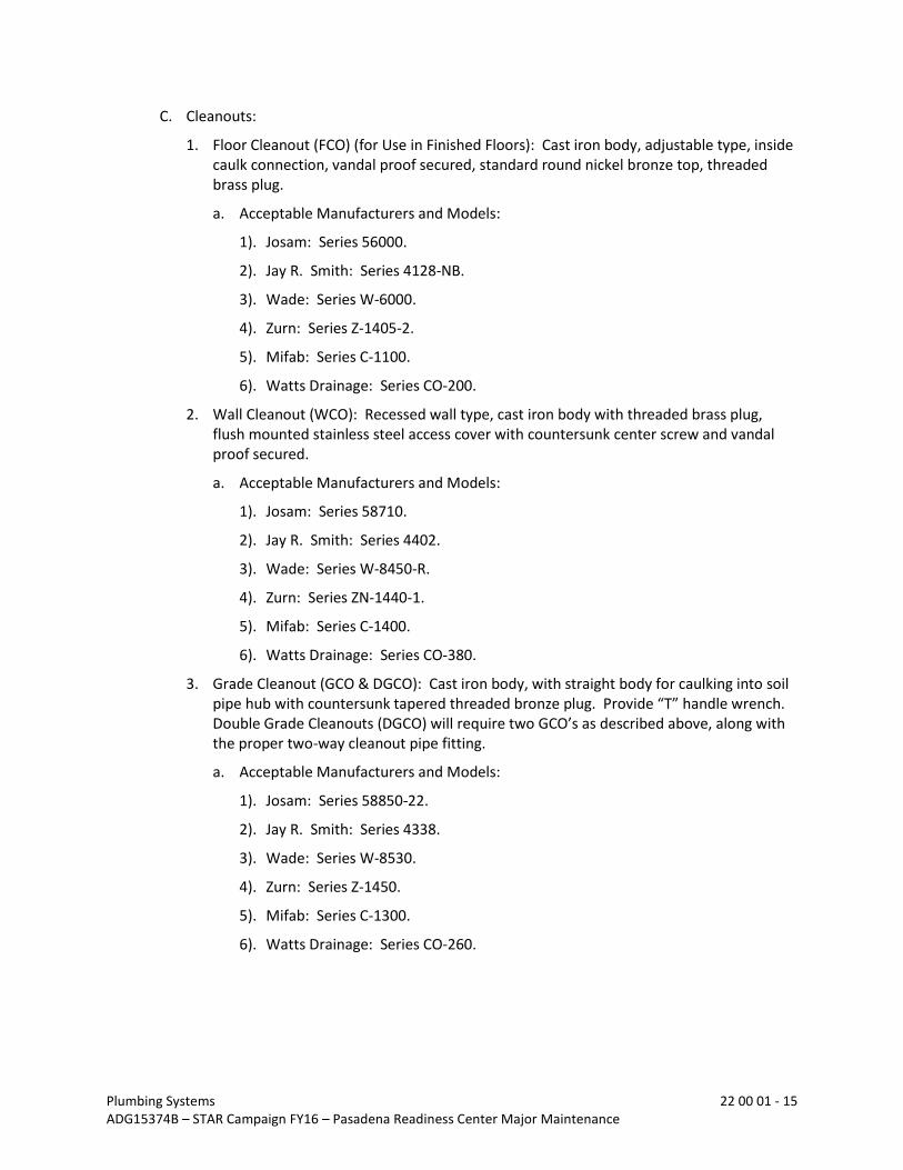
C. Cleanouts:
1. Floor Cleanout (FCO) (for Use in Finished Floors): Cast iron body, adjustable type, inside caulk connection, vandal proof secured, standard round nickel bronze top, threaded brass plug.
a. Acceptable Manufacturers and Models:
1). Josam: Series 56000.
2). Jay R. Smith: Series 4128-NB.
3). Wade: Series W-6000.
4). Zurn: Series Z-1405-2.
5). Mifab: Series C-1100.
6). Watts Drainage: Series CO-200.
2. Wall Cleanout (WCO): Recessed wall type, cast iron body with threaded brass plug, flush mounted stainless steel access cover with countersunk center screw and vandal proof secured.
a. Acceptable Manufacturers and Models:
1). Josam: Series 58710.
2). Jay R. Smith: Series 4402.
3). Wade: Series W-8450-R.
4). Zurn: Series ZN-1440-1.
5). Mifab: Series C-1400.
6). Watts Drainage: Series CO-380.
3. Grade Cleanout (GCO & DGCO): Cast iron body, with straight body for caulking into soil pipe hub with countersunk tapered threaded bronze plug. Provide “T” handle wrench. Double Grade Cleanouts (DGCO) will require two GCO’s as described above, along with the proper two-way cleanout pipe fitting.
a. Acceptable Manufacturers and Models:
1). Josam: Series 58850-22.
2). Jay R. Smith: Series 4338.
3). Wade: Series W-8530.
4). Zurn: Series Z-1450.
5). Mifab: Series C-1300.
6). Watts Drainage: Series CO-260.

Plumbing Systems 22 00 01 - 16 ADG15374B – STAR Campaign FY16 – Pasadena Readiness Center Major Maintenance
D. Backflow Preventers:
1. Reduced Pressure Backflow Preventers (RPBP):
a. Reduced pressure backflow preventer (2-1/2 inches thru 8 or 10 inches): ANSI/ASSE 1013; complete unit of two independently acting check valves together with an automatically operating pressure relief valve, two gate valves, and four test cocks, bronze or iron body with bronze internal parts, 150 psi working pressure, and shall comply with AWWA Standard C506.
1). Acceptable Manufacturers and Models:
a). Watts: 957.
b). AMES: Silver Bullet – 4000 SS.
E. Backflow Enclosures:
1. Reduced Pressure Backflow Preventer Enclosure:
a. A freeze and vandal protective enclosure, marine grade reinforced aluminum. Enclosures shall have a fully insulated drain panel designed to remain closed except when discharging water. The drain panel size shall be sized to accommodate the maximum discharge for backflow installations. The enclosure shall be mounted securely to a concrete pad and remain locked even if outside screws are removed
1). Acceptable Manufacturers and Models:
a). Safe T Cover: 300-AL
b). Watts: WB-300.
F. Water Hammer Arrestors:
1. Water Hammer Arrestors (WHA): ANSI A112.26.1, ASSE 1010, and PDI WH-201; permanently sealed bellows or expanding chamber. Sizing designations indicated on the Drawings are standard classifications established by Plumbing and Drainage Institute “Standard PDI-WH201.” Verify that system pressure meets minimum required for water hammer arrestor provided.
a. Acceptable Manufacturers and Models:
1). Josam: 75000.
2). Jay R. Smith: 5000.
3). Wade: “SHOKSTOP” Series.
4). Zurn: Z-1700.
5). Sioux Chief: “Hydra-Rester” Series.
6). Watts: No. 15M2 Series.
7). PPP: SC & SWA Series.
8). Mifab: WHB Series.

Plumbing Systems 22 00 01 - 17 ADG15374B – STAR Campaign FY16 – Pasadena Readiness Center Major Maintenance
G. Trap Seals:
1. Trap Seals (TS): Flexible elastomeric or neoprene trap seal device utilizes a normally closed seal to prevent evaporation of the liquid trap seal and also protects against sewer gases from backing up into the building or surrounding areas. The device opens when liquid enters to allow drainage to flow through into the building drainage piping, and closes when there is no drainage flow entering the drain. Provide in all floor drains, floor sinks, area drains and hub drains connected to the sanitary sewer system or to other systems that may have sewer gases present in the drainage system.
a. Acceptable Manufacturers and Models:
1). ProVent Systems, Inc.: ProSet Trap Guard Series. 800.262.5355 or www.trapguard.com.
2). Mifab: Mi-Gard Series.
3). SureSeal.
4). Jay R. Smith Mfg. Co.: Quad Close Series.
H. Hose Bibbs:
1. Hose Bibb (HB): Chrome plated brass, provided with wall flange, 1/2-inch female NPT inlet by 3/4-inch male N.H.T. outlet, with chrome plated vacuum breaker in conformance with ANSI/ASSE 1011.
a. Acceptable Manufacturers and Models:
1). Chicago Faucet: 15-E27 or 7-E27.
2). T&S Brass: B-702-B-972.
3). Royal Brass: 5115-136-G.
4). Woodford: 24P.
5). Watts: SC8-1.
I. Wall Hydrants:
1. Non-Freeze Wall Hydrant (NFWH1): ANSI/ASSE 1019; recessed box wall hydrant type, with chrome plated brass or nickel bronze finish on brass castings, freezeless, 3/4-inch hose thread nozzle, integral vacuum breaker, with loose key handle for box and valve.
a. Acceptable Manufacturers and Models:
1). Woodford: B65.
2). Josam: 71150.
3). Jay R. Smith: 5509.
4). Wade: W-8625.
5). Zurn: Z-1300.
6). Watts HY-725.

Plumbing Systems 22 00 01 - 18 ADG15374B – STAR Campaign FY16 – Pasadena Readiness Center Major Maintenance
J. Ice Maker Outlet Boxes:
1. Ice Maker Outlet Box (IMOB): Recessed 16-gauge steel cabinet with white powder coated finish, 1/2-inch domestic water ball valve meeting lead-free requirements.
a. Acceptable Manufacturers and Models:
1). Guy Gray: MIB1DAB, or approved equal.
K. Pipe Hangers and Supports:
1. Hangers for pipe sizes 1/2 to 1-1/2 inches: Malleable iron, adjustable swivel, split ring.
2. Hangers for pipe sizes 2 to 4 inches and cold pipe sizes 6 inches and over: Carbon steel, adjustable, clevis.
3. Multiple or Trapeze Hangers: Steel channels with welded spacers and hanger rods; cast iron roll and stand for hot pipe sizes 6 inches and over.
4. Vertical Support: Steel riser clamp.
5. Floor Support for pipe sizes to 4 inches and all cold pipe sizes: Cast iron adjustable pipe saddle, locknut nipple, floor flange, and concrete pier or steel support.
6. Copper Pipe Support: Carbon steel ring, adjustable, copper plated.
7. Shields for insulated piping 2 inches and smaller: 18 gage galvanized steel shield over insulation in 180 degree segments, minimum 12-foot long at pipe support.
8. Shields for insulated piping 2-1/2 inches and larger (Except Cold Water Piping): Pipe covering protective saddles.
9. Shields for insulated cold water piping 2-1/2 inches and larger: Hard block non-conducting saddles in 90 degree segments, 12-inch minimum length, block thickness same as insulation thickness.
10. Shields for Vertical Copper Pipe Risers: Sheet lead.
11. Adjustable rooftop pipe supports:
a. Adjustable rooftop supports for piping shall be provided for installation without requiring roof penetrations, flashing, or damage to the roofing material. Support Bases shall be made of a UV-stabilized, EPDM rubber sized to fit the diameter of the pipe or conduit being supported. The support shall contain appropriate additives for UV protection.
b. The support shall allow for tool-free pipe installation and integrally-connected height adjustability of up to 4”, 6” or 7” in ½” increments.
c. The support shall have a continuous bottom surface to minimize point loading of the roof membrane. The support shall not have discontinuities, cutouts, or pockets on the surface contacting the roof. The placement of slip sheets or mats between the support and the roof surface shall not satisfy the continuous bottom surface requirement.
d. Acceptable Manufacturers and Models:
Erico, Caddy Pyramid or approved equal.

Plumbing Systems 22 00 01 - 19 ADG15374B – STAR Campaign FY16 – Pasadena Readiness Center Major Maintenance
12. Support horizontal piping as follows:
Pipe Size Max. Hanger Spacing Hanger Diameter
1/2” to 1-1/4” 6’-6” 3/8”
1-1/2” to 2” 10’-0” 3/8”
2-1/2” to 3” 10’-0” 1/2”
4” to 6“ 10’-0” 5/8”
8” to 12” 14’-0” 7/8”
PVC (All Sizes) 6’-0” 3/8”
C.I. Bell and Spigot (or No-Hub) 5’-0” and at Joints
13. Hanger Notes:
a. Install hangers to provide minimum 1/2-inch space between finished covering and adjacent Work.
b. Place a hanger within 12 inches of each horizontal elbow.
c. Use hangers with 1-1/2-inch maximum vertical adjustment.
d. Support horizontal cast iron pipe adjacent to each hub, with 5-inch maximum spacing between hangers.
e. Support vertical piping at every floor. Support vertical cast iron pipe at each floor at hub.
f. Where several pipes can be installed in parallel and at same elevation, provide multiple or trapeze hangers. Consult with project structural engineer for approval.
g. Support riser piping independently of connected horizontal piping.
h. For below floor hanger installations, place one hanger at each pipe penetration thru a concrete grade beam, at either side, a minimum of 12 inches from the face of the grade beam.
L. Hanger Rods:
1. Steel Hanger Rods: Threaded both ends.
M. Inserts:
1. Inserts: Malleable iron case of galvanized steel shell and expander plug for threaded connection with lateral adjustment, top slot for reinforcing rods, lugs for attaching to forms; size inserts to suit threaded hanger rods.
N. Insulation:
1. Pipe insulation for domestic hot and cold water pipe.
a. Heavy duty preformed fiberglass (ASTM C547, type 1, 2 or 3). Schuller, Knauf or Certainteed.
b. Preformed flexible elastomeric insulation (ASTM C534) Armstrong “Armaflex”, or Schuller “Rubatex.”
Plumbing Systems 22 00 01 - 20 ADG15374B – STAR Campaign FY16 – Pasadena Readiness Center Major Maintenance
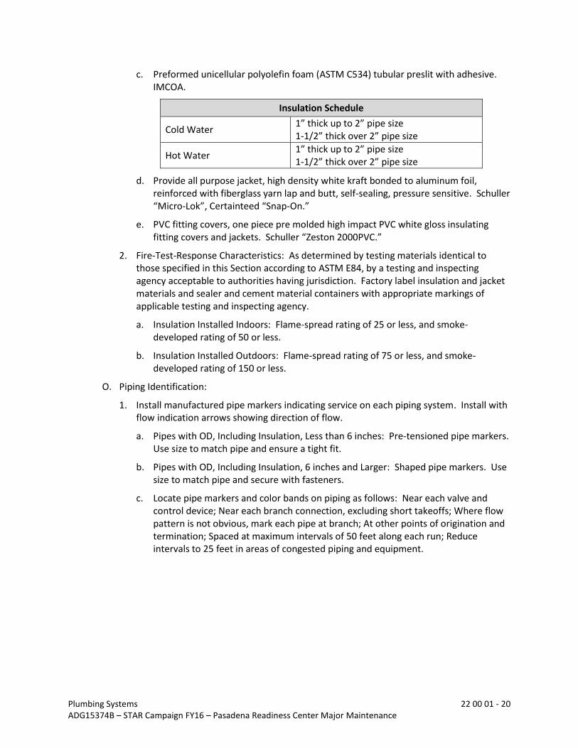
c. Preformed unicellular polyolefin foam (ASTM C534) tubular preslit with adhesive. IMCOA.
Insulation Schedule
Cold Water 1” thick up to 2” pipe size 1-1/2” thick over 2” pipe size
Hot Water 1” thick up to 2” pipe size 1-1/2” thick over 2” pipe size
d. Provide all purpose jacket, high density white kraft bonded to aluminum foil, reinforced with fiberglass yarn lap and butt, self-sealing, pressure sensitive. Schuller “Micro-Lok”, Certainteed “Snap-On.”
e. PVC fitting covers, one piece pre molded high impact PVC white gloss insulating fitting covers and jackets. Schuller “Zeston 2000PVC.”
2. Fire-Test-Response Characteristics: As determined by testing materials identical to those specified in this Section according to ASTM E84, by a testing and inspecting agency acceptable to authorities having jurisdiction. Factory label insulation and jacket materials and sealer and cement material containers with appropriate markings of applicable testing and inspecting agency.
a. Insulation Installed Indoors: Flame-spread rating of 25 or less, and smoke-developed rating of 50 or less.
b. Insulation Installed Outdoors: Flame-spread rating of 75 or less, and smoke-developed rating of 150 or less.
O. Piping Identification:
1. Install manufactured pipe markers indicating service on each piping system. Install with flow indication arrows showing direction of flow.
a. Pipes with OD, Including Insulation, Less than 6 inches: Pre-tensioned pipe markers. Use size to match pipe and ensure a tight fit.
b. Pipes with OD, Including Insulation, 6 inches and Larger: Shaped pipe markers. Use size to match pipe and secure with fasteners.
c. Locate pipe markers and color bands on piping as follows: Near each valve and control device; Near each branch connection, excluding short takeoffs; Where flow pattern is not obvious, mark each pipe at branch; At other points of origination and termination; Spaced at maximum intervals of 50 feet along each run; Reduce intervals to 25 feet in areas of congested piping and equipment.

Plumbing Systems 22 00 01 - 21 ADG15374B – STAR Campaign FY16 – Pasadena Readiness Center Major Maintenance
4.00 EXECUTION
4.01 PREPARATION
A. Establish invert elevations for drainage piping within 5 feet of building. Minimum slopes for drainage pipe is 1/4 inch per foot for 2 1/2-inch diameter and less and 1/8 inch per foot for 3-inch diameter pipe and greater.
B. Close equipment shutoff valves before turning off gas to premises or piping section.
C. Inspect natural gas piping according to NFPA 54 to determine that natural gas utilization devices are turned off in piping section affected.
D. Comply with NFPA 54, Part 1, “Prevention of Accidental Ignition” Paragraph.
4.02 INSTALLATION
A. Pipe, Valves and Fittings:
1. Provide non-conducting dielectric connections wherever jointing dissimilar metals.
2. Provide clearance for installation of insulation, and access to valves and fittings.
3. Provide access doors where valves and equipment are not accessible. Coordinate size and location of access doors with applicable Section.
4. Install sanitary piping true to line with proper grading. Connect horizontal branches to one another with 45 degrees “Y” fittings, combination “Y” and 1/8 bend fittings. Connect horizontal lines to vertical stacks using 45 degrees “Y” branches, 60 degree “Y” branches, or combination “Y” and 1/8 bend fittings. Horizontal branches turning down to vertical stacks may use a short sweep or 1/2 bend. Branches connecting to mains or to other branches shall enter the branch line at a 45 degree angle, tilted 45 degrees upward, so that the entry is from the side and top.
5. Materials exposed within ducts or plenums (ceiling spaces used as supply or return air plenums) shall have a flame-spread index of not more than 25 and a smoke-developed rating of not more than 50 when tested in accordance with the test for Surface Burning Characteristics of Materials, UBC Standard. Wrap or enclose with rated materials, any CPVC, PVC or PEX piping installed in rated spaces, including return air plenums.
6. Piping hangers shall be sized large enough to allow insulation to pass through. Hangers for piping 2-1/2 inches and greater shall be provided with pipe covering protection saddle, or high compressive strength insulation saddle. Hangers for piping 2 inches and less shall be provided with pipe covering shields. On cold water piping provide vapor barrier through hanger.
7. Anchor piping with regard to the transmission of vibration and noise. Securely anchor copper piping to studs or wood blocking with “C” clamp of proper size for piping. At each fixture location where the piping penetrates the partition, back the elbow inside the partition, or chase, with wood blocking. Anchor with “C” clamps or cast brass drop ear elbows to prevent movement. Do not use wire as an anchoring device.
8. Piping shall not come into direct contact with metal studs, beams, or other construction elements. Provide a non-metallic separation between dissimilar metals when copper piping is installed in direct contact with steel.

Plumbing Systems 22 00 01 - 22 ADG15374B – STAR Campaign FY16 – Pasadena Readiness Center Major Maintenance
9. Install unions in piping 2 inches and smaller and flanges in piping 2-1/2 inches and larger, adjacent to each valve and at final connection to each piece of equipment having threaded pipe connection.
10. Install piping adjacent to equipment and specialties to allow service and maintenance.
11. Install piping free of sags and bends.
12. Install strainers on inlet side of service regulators.
13. Terminate vent piping with turned-down, reducing-elbow fittings with corrosion-resistant insect screens in large end.
14. Install underground, plastic, gas distribution piping according to ASTM D2774.
15. Install plastic shutoff valves on branch connections to existing underground gas distribution piping. Install valves with valve boxes.
16. Install metal shutoff valves on aboveground, gas distribution piping.
17. Install aboveground, shutoff valves in accessible locations, protected from physical damage. Include metal tag, attached to valve with metal chain, indicating piping systems supplied.
18. Install shutoff valves and strainers upstream from service regulators. Shutoff valves are not required at second regulators if two regulators are installed in series.
19. Install shutoff valves upstream from service meters. Install dielectric fittings downstream from service meters, as required.
20. Install pressure-relief or pressure-limiting devices so they can be readily operated to determine if device is free, tested to determine pressure at which they will operate, and examined for leakage if closed.
21. Do not use gas piping as grounding electrode.
22. Equipment Nameplates and Signs: Install engraved plastic-laminate equipment nameplates and signs on or near each service regulator and meter.
a. Text: Distinguish between multiple units, inform operator of operational requirements, indicate safety and emergency precautions, and warn of hazards and improper operations, in addition to name of identified unit.
23. Warning Tapes: Arrange for installation of continuous, underground, detectable warning tape during backfilling of trenches for piping.
B. Plumbing Specialties and Equipment:
1. Pipe relief valves and drains to nearest floor drain. Minimum slope 1/16 inch per foot. Provide 2-inch air gap.
2. Install equipment plumb and square to wall on a 4-inch thick (minimum) reinforced concrete housekeeping pad.
3. Provide all interconnecting electrical power and control wiring from control panels to equipment and accessories for a complete operable systems. All exposed wiring shall be in conduit. Comply with Division 26.

Plumbing Systems 22 00 01 - 23 ADG15374B – STAR Campaign FY16 – Pasadena Readiness Center Major Maintenance
4. Extend cleanouts to finished floor or wall surface. Lubricate threaded cleanout plugs with mixture of graphite and linseed oil. Ensure clearance at cleanout for rodding of drainage system.
5. Encase grade cleanouts in concrete flush with grade when not located in concrete, pavement, sidewalk, etc.
6. Grade cleanouts located in pavement or sidewalks shall have a brass or cast iron cover that extends to grade and a brass cap shall be installed.
7. Trap all drains connected to the sanitary sewer.
8. Install floor and area drains with top depressed 1/2 inch below finished floor elevation.
9. In addition to cleanouts, as shown on the Drawings, Contractor shall provide any additional cleanouts required by local codes and ordinances at no additional cost to the Owner.
10. Outlet of plumbing vents and flues shall be located a minimum of 25 feet from fresh air intakes. Provide offset as required.
11. Relief valve discharge drain from reduced pressure backflow preventers shall be piped full outlet size down to nearest floor sink. Drain line shall terminate above floor drain with air gap unless otherwise indicated on the drawings.
12. Prior to ordering and installing water hammer arrestors, verify that the pressure at the point of installation does not drop to below 30 psig at any time. If the pressure drops below 30 psig, do not install piston type water hammer arrestors. Install bellows type arrestors under low pressure circumstances. Provide access panel directly in front of each water hammer arrestor.
13. Install backflow preventers of type, size, and capacity indicated. Include valves and test cocks. Install according to requirements of plumbing and health department and authorities having jurisdiction.
14. Do not install backflow preventers that have relief drain in vault or in other spaces subject to flooding.
C. Plumbing Fixtures and Connections:
1. Furnish and install plumbing fixtures, as noted on the Drawings. Each fixture shall be complete with trim and fittings, including traps and supply fittings. Set fixture with close tolerance to wall and floor surfaces.
2. Provide all wall mounted fixtures with floor carriers. Install and secure fixtures in place with wall supports carriers and bolts. Exposed bolts, nuts, etc. shall be stainless steel or chrome-plated brass.
3. Seal fixtures to wall and floor surfaces with white mildew resistant sealant.
4. Mount fixtures to Architectural Drawings interior wall elevations, manufacturers recommended elevations or the requirements of the ADA or TAS, whichever is applicable.
5. Provide removable insulation covering on stops and supplies and drains and P-traps on all handicapped lavatories. All lavatories in rooms with handicapped water closets are considered handicapped lavatories.

Plumbing Systems 22 00 01 - 24 ADG15374B – STAR Campaign FY16 – Pasadena Readiness Center Major Maintenance
6. Provide accessible stops on all water supplies to fixtures and equipment.
7. Provide accessible water hammer arresters on hot and cold water supplies to plumbing fixtures and/or fixture groups in accordance with Standard PDI-WH-201. Water hammer arresters shall be as shown on diagrams and if not shown, provide for plumbing fixtures and/or fixture groups in accordance with Standard PDI-WH-201.
8. Provide drainage and vent piping run-outs to plumbing fixtures and drains, with approved trap, of sizes indicated, but in no case smaller than required by the governing Plumbing Code.
9. Provide drainage piping run-outs to urinals of cast iron material. Copper or brass material is prohibited.
D. Trenching, Excavation and Backfill:
1. Perform excavating and backfilling necessary for the installation of Work. Shore, bail, pump and maintain all trenches dry until the Work is completed. Keep trenches open until piping has been inspected, tested and approved. Take necessary precautions to protect the public from open trenches. Erect and maintain barricades and warning devices in accordance with OSHA requirements.
2. Backfill trenches after piping has been tested and approved. Material for backfilling shall be a clean, sandy loam up to 4 inches above the top of pipe. Above that point, use overburden removed in the excavation process. Overburden shall be free of trash, debris, rocks or boulders. Deposit backfill material in 12-inch layers and compact to the density of the adjacent, undisturbed soil. Remove all excess material from the Site.
4.03 TESTING
A. Piping Systems:
1. General: Furnish pumps, compressors,-gauges, equipment and personnel required, and test as necessary to demonstrate the integrity of the finished installation.
2. Soil, Sanitary Waste and Vent: Unless otherwise directed by the authority having jurisdiction, plug all openings except for the highest opening and fill with water to the point of overflow. Perform a water test consisting of no less than 10 feet of head shall be applied to the system. Allow to stand 1 hour or longer as required. The system should be water tight and leak free. If leaks exist, repair and retest.
3. Water: Unless otherwise directed by the authority having jurisdiction, hydrostatically test and make tight the entire system at 120 psi. Retain for 4 hours. The system should be water tight and leak free. If leaks exist, repair and retest.
4. Natural gas: Unless otherwise directed by the authority having jurisdiction, pneumatically test and make tight at 1-1/2 times the normal operating pressure and not less than 50 psi. Where the test pressure exceeds 125 psi, the test pressure shall not exceed a value that produces a hoop stress in the piping greater than 50 percent of the specified minimum yield strength of the pipe. Reduce test pressure if required. Retain for 4 hours minimum or not less than 1/2 hour for each 500 cubic feet of pipe volume or fraction thereof. When testing a system having a volume of less than 10 cubic feet, the test duration shall be permitted to be reduced to 10 minutes. For piping systems having a volume of more than 24,000 cubic feet, the duration of the test shall not be required

Plumbing Systems 22 00 01 - 25 ADG15374B – STAR Campaign FY16 – Pasadena Readiness Center Major Maintenance
The system should be air tight and leak free. If leaks exist, repair and retest. Verify capacities and pressure ratings of service regulators and meters. Verify correct pressure settings for service regulators. PROVIDE A CERTIFICATE OF FLUSHING AND TESTING TO THE OWNER UPON COMPLETION, INDICATING THAT THE SYSTEM HAS BEEN TESTED IN ACCORDANCE WITH THIS SPECIFICATION AND NFPA 54, THE NATIONAL FUEL GAS CODE. CERTIFICATE SHALL INDICATE TESTING COMPANY NAME AND PERSONNEL COMPLETING TESTS AND TWO WITNESSES COMPLETE WITH NAMES AND ADDRESSES.DEMONSTRATION OF EQUIPMENT
4.04 DEMONSTRATION OF EQUIPMENT
A. Prior to final acceptance, Contractor and Manufacturer’s Representative of Domestic Water Heaters and associated accessories and controls, each shall provide a minimum of 4 hours (or as long as required by the Owner) to demonstrate to the Owner the proper operation of the equipment.
B. Prior to final acceptance, Contractor shall provide a minimum of 4 hours (or as long as required by the Owner) to demonstrate to the Owner the proper operation of all the plumbing equipment and associated accessories and controls.
4.05 FLUSHING
A. General: After piping systems have been tested and approved, systems shall be flushed. Furnished compressors, pumps, equipment, personnel, etc. required to flush piping systems.
B. Soil, Sanitary Waste and Vent: Unless otherwise directed by the authority having jurisdiction, thoroughly flush piping systems with water until free of debris, or detrimental materials that may cause partial or full blockage. As a minimum comply with the International Plumbing Code, Section 302, of the latest edition.
C. Water Piping: Unless otherwise directed by the authority having jurisdiction, flush piping with water until water flows clear for a minimum of 60 seconds per 100 linear feet of piping being flushed at a velocity of 9 feet per second.
D. Natural Gas Piping: Unless otherwise directed by the authority having jurisdiction, flush piping with air until air flows clear for a minimum of 60 seconds per 100 linear feet of piping being flushed at 25 cfm per 1-inch diameter of pipe.
E. All strainers and filters shall be cleaned and replaced prior to start-up.
4.06 DISINFECTION OF DOMESTIC WATER PIPING SYSTEM
A. Prior to starting Work, verify system is complete, flushed and clean.
B. Inject disinfectant, free chlorine in liquid, powder, tablet or gas form, throughout system to obtain 50 to 80 mg/L residual.
C. Bleed water from outlets to ensure distribution and test for disinfectant residual at minimum five remote outlets.
D. Maintain disinfectant in system for 24 hours.
E. Flush disinfectant from system until residual equal to that of incoming water or 1.0 mg/L.

Plumbing Systems 22 00 01 - 26 ADG15374B – STAR Campaign FY16 – Pasadena Readiness Center Major Maintenance
F. Take Samples no sooner than 24 hours after flushing, from five remote outlets and from water entry, and analyze in accordance with AWWA C601.
G. Disinfection and disinfection procedures shall be witnessed and approved by the Owners Representative.
H. After disinfection is completed, submit “Disinfection Certificate of Approval” for domestic water piping systems to the Owners Representative stating that all test results are satisfactory. Certificate of Approval must be signed by Contractor, Testing Laboratory. Certificate shall show the date, time and residual of each of the following tests:
1. Initial disinfection residual (50 ppm minimum) - five Samples.
2. Final disinfection residual (25 ppm minimum) - five Samples.
3. After flushing residual (5 ppm maximum) - five Samples.
4. Analyze in accordance AWWA C601 - five Samples.
4.07 CLOSING IN UNINSPECTED WORK
A. Do not cover up or enclose Work until it has been properly and completely inspected and approved. Should any of the Work be covered up or enclosed prior to all required inspections and approvals, uncover the Work as required. After it has been completely inspected and approved, make all repairs and replacements as necessary to the satisfaction of the Owner’s representative. Repairs and replacements shall be at no additional cost to the Owner.
END OF SECTION

Dedicated Outside Air System 23 74 09 - 1 ADG15374B – STAR Campaign FY16 – Pasadena Readiness Center Major Maintenance
23 74 09 DEDICATED OUTSIDE AIR SYSTEM
1.00 GENERAL
1.01 RELATED DOCUMENTS
A. Drawings and general provisions of the Contract, including General and Supplementary Conditions apply to this Section.
1.02 SUMMARY
A. This Section includes the following equipment:
1. Dedicated outside air systems (DOAS).
1.03 DEFINITIONS
A. BAS: Building Automation System.
1.04 SUBMITTALS
A. Product Data: Include manufacturer’s technical data for each model indicated, including rated capacities, dimensions, required clearances, characteristics, furnished specialties, and accessories.
B. Shop Drawings: Detail equipment assemblies and indicate dimensions, weights, loads, required clearances, method of field assembly, components, and location and size of each field connection.
C. Wiring Diagrams: Power, signal, and control wiring.
D. On-Board Controller: Include detailed technical data for on-board programmable controller, available input and output control points, programmed setpoints, control schematic and sequence of operations.
E. Factory & Field Quality-Control Test Reports.
F. Operation and Maintenance Data: Include emergency, operation, and maintenance manuals.
G. Warranties: Special warranties specified in this Section.
1.05 QUALITY ASSURANCE
A. Product Options: Drawings indicate size, profiles, and dimensional requirements of DOA. These are based on the Basis of Design system.
B. Electrical Components, Devices, and Accessories: Listed and labeled as defined in NFPA 70, Article 100, by a testing agency acceptable to authorities having jurisdiction, and marked for intended use.
C. Energy-Efficiency Ratio: Equal to or greater than prescribed by ASHRAE 90.1, “Energy Efficient Design of New Buildings except Low-Rise Residential Buildings” and International Energy Conservation Code, whichever is greater.”

Dedicated Outside Air System 23 74 09 - 2 ADG15374B – STAR Campaign FY16 – Pasadena Readiness Center Major Maintenance
D. Coefficient of Performance: Equal to or greater than prescribed by ASHRAE 90.1, “Energy Efficient Design of New Buildings except Low-Rise Residential Buildings” and International Energy Conservation Code, whichever is greater.”
E. ARI Certification: Units shall be ARI certified and listed.
F. ARI Compliance: Rate rooftop air-conditioner capacity according to ARI 340/360, “Commercial and Industrial Unitary Air-Conditioning and Heat Pump Equipment.”
1. Sound Power Level Ratings: Comply with ARI 270, “Sound Rating of Outdoor Unitary Equipment.”
1.06 COORDINATION
A. Coordinate location of existing roof curbs and installation of equipment supports.
1.07 WARRANTY
A. Special Warranty: Manufacturer’s standard form in which manufacturer agrees to replace components of DOAS that fails in materials or workmanship within specified warranty period.
1. Warranty Period for Compressors: Manufacturer’s standard, but not less than five (5) years from equipment start-up or 6 months after shipment (whichever comes first).
2. Warranty Period for Heat Exchangers: Manufacturer’s standard, but not less than five (5) years from equipment start-up or 6 months after shipment (whichever comes first).
3. Warranty Period for Control Boards: Manufacturer’s standard, but not less than three (3) years from equipment start-up or 6 months after shipment (whichever comes first).
4. Warranty Period for Variable-Speed Fan Motors: Manufacturer’s standard, but not less than three (3) years from equipment start-up or 6 months after shipment (whichever comes first).
5. Warranty Period for temperature and humidity sensors: Manufacturer’s standard, but not less than three (3) years from equipment start-up or 6 months after shipment (whichever comes first).
1.08 EXTRA MATERIALS
A. Furnish extra materials described below that match products installed and that are packaged with protective covering for storage and identified with labels describing contents.
1. Fan Belts: One set for each belt-drive fan.
2. Filters: One set of filters for each unit.
2.00 PRODUCTS
2.01 DEDICATED OUTSIDE AIR SYSTEMS (DOAS)
A. Manufacturers: Subject to compliance with requirements, provide products by the manufacturers specified below with no exceptions.
1. Mitsubishi

Dedicated Outside Air System 23 74 09 - 3 ADG15374B – STAR Campaign FY16 – Pasadena Readiness Center Major Maintenance
2. Engineered Air
3. Aaon
4. Munters
5. Desert Aire
B. Description: Factory assembled and tested; designed for exterior installation; consisting of compressor, indoor and outside refrigerant coils, indoor fan and outside coil fan, refrigeration and temperature controls, filters, and dampers.
C. Base and Cabinet:
1. The unit shall be double wall construction with heavy duty minimum 20 gauge G-90 galvanized steel. Gasketed access doors shall be minimum 20 gauge steel with 2" (R-13) insulation and a 24 gauge galvanized steel liner. Standard outer panels will be insulated with 2” (R-13) insulation with a 24 gauge galvanized steel interior liner. The underside of the base panel shall be insulated with 3/8" closed cell foam insulation. Base pan of the unit shall have no openings or penetrations. The design of the cabinet shall allow access to the compressor and electrical control panel without impairing unit operation.
2. Cabinet shall be designed for vertical supply air duct connection.
3. Service access doors shall also be mounted with stainless steel hinges and equipped with 1/4 turn cam operated adjustable compression type latches.
4. Provide perforated-metal liner knockouts for electrical and piping connections, exterior condensate drain connections and lifting lugs. Knockouts shall be thru unit sidewall.
5. The condensers shall have a vinyl coated wire coil guard to protect the condensers as well as the compressors.
6. Paint Finish: polyester urethane powder coat with primer.
D. IAQ Condensate Drain Pan: The condensate drain pan shall be double sloped to comply with ASHRAE Standard 62-1089R and shall be fabricated from heavy gauge stainless steel. The bottom of the condensate drain pan shall be insulated with closed cell neoprene insulation. The drain pan shall be furnished with an MPT drain fitting positioned at the exterior of the cabinet. The weight of the coil and other components shall not compress the insulation thus reducing its insulation value. A float switch shall be provided in the condensate drain pan and shall be hardwired to shut down the unit if the switch trips. Condensate float switch alarm shall be generated on the in-built controller and BAS system. The alarm shall stay on until the issue has been resolved.
E. Supply Fan Section:
1. The standard fan assembly shall be a plenum fan assembly mounted on rubber vibration isolation. The shaft is direct driven and connected to a nominal 1725 RPM open drip proof motor with sealed ball bearings. The bearings on both the blower shaft and motor are permanently lubricated. The supply fan shall be on a slide out deck for removal from the cabinet to service or inspect.

Dedicated Outside Air System 23 74 09 - 4 ADG15374B – STAR Campaign FY16 – Pasadena Readiness Center Major Maintenance
2. The supply fan motor shall be premium efficiency, ODP, and externally protected (manual reset).
F. Variable Frequency Drive (VFD): Manufacturer furnished and wired integral VFD shall modulate supply air fan speed per control sequence. VFD shall be suitable for operation in a 50oC ambient temperature. VFD shall be housed in a NEMA 3R enclosure as a minimum.
G. Condenser Fans and Motors: Condenser fan motors are direct-drive and shall be fitted with permanently lubricated sealed ball bearings protected with shaft mounted rain shields. Condenser fans shall be vertical discharge and shall be constructed with steel spider and formed aluminum blades securely riveted together. Fans shall be statically and dynamically balanced to provide efficient operation.
H. Refrigeration System:
1. The refrigerant system shall operate with R-410A refrigerant and shall include the compressor, crankcase heater, copper-tube, aluminum finned condenser and evaporator coils. The refrigerant circuit shall include check valves, filter/drier, high pressure safety control (manual-reset), low pressure control/loss of charge protector (auto-reset), dual gauge connections for high and low pressure readings, thermostat for coil freeze protection during low-ambient temperature operation and thermal expansion valve with adjustable superheat. The condensing section of the unit shall be integral to the unit and shall be manufactured by the air conditioning unit manufacturer.
2. Evaporator and Condenser Coils: Evaporator coil shall be enhanced surface aluminum fins, formed on multiple rows of seamless rifled copper tubing, arranged in staggered tube configuration with galvanized steel header plates. These tubes are mechanically expanded, firmly bonding the tube to the shoulder of each fin.
3. Modulating hot has reheat coil for precise temperature and humidity control.
I. Compressor(s): Two hermetically sealed variable capacity scroll compressors, include integral vibration isolators, internal overcurrent and overtemperature protection, internal pressure relief, and crankcase heaters. Compressor shall be warranted by manufacturer for five years from date of installation.
J. Filters: 2-inch (50-mm) thick, fiberglass, pleated, throwaway filters in filter rack.
K. Heat Exchanger: Stainless steel construction for natural gas-fired burners with the following controls:
1. Redundant single or dual gas valve with manual shutoff.
2. Direct-spark pilot ignition.
3. Electronic flame sensor.
4. Induced-draft blower.
5. Flame rollout switch.
6. Modulating heat.
L. Outside-Air Damper: The unit shall be equipped with a factory installed linked damper blades, for 0 to 100 percent outside air, with fully modulating, spring-return damper motor and weatherproof, outside-air intake hood with bird screen.
Dedicated Outside Air System 23 74 09 - 5 ADG15374B – STAR Campaign FY16 – Pasadena Readiness Center Major Maintenance
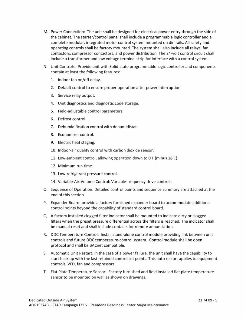
M. Power Connection: The unit shall be designed for electrical power entry through the side of the cabinet. The starter/control panel shall include a programmable logic controller and a complete modular, integrated motor control system mounted on din rails. All safety and operating controls shall be factory mounted. The system shall also include all relays, fan contactors, compressor contactors, and power distribution. The 24-volt control circuit shall include a transformer and low voltage terminal strip for interface with a control system.
N. Unit Controls: Provide unit with Solid-state programmable logic controller and components contain at least the following features:
1. Indoor fan on/off delay.
2. Default control to ensure proper operation after power interruption.
3. Service relay output.
4. Unit diagnostics and diagnostic code storage.
5. Field-adjustable control parameters.
6. Defrost control.
7. Dehumidification control with dehumidistat.
8. Economizer control.
9. Electric heat staging.
10. Indoor-air quality control with carbon dioxide sensor.
11. Low-ambient control, allowing operation down to 0 F (minus 18 C).
12. Minimum run time.
13. Low-refrigerant pressure control.
14. Variable-Air-Volume Control: Variable-frequency drive controls.
O. Sequence of Operation: Detailed control points and sequence summary are attached at the end of this section.
P. Expander Board: provide a factory furnished expander board to accommodate additional control points beyond the capability of standard control board.
Q. A factory installed clogged filter indicator shall be mounted to indicate dirty or clogged filters when the preset pressure differential across the filters is reached. The indicator shall be manual-reset and shall include contacts for remote annunciation.
R. DDC Temperature Control: Install stand-alone control module providing link between unit controls and future DDC temperature-control system. Control module shall be open protocol and shall be BACnet compatible.
S. Automatic Unit Restart: In the case of a power failure, the unit shall have the capability to start back up with the last retained control set points. This auto restart applies to equipment controls, VFD, fan and compressors.
T. Flat Plate Temperature Sensor: Factory furnished and field installed flat plate temperature sensor to be mounted on wall as shown on drawings.

Dedicated Outside Air System 23 74 09 - 6 ADG15374B – STAR Campaign FY16 – Pasadena Readiness Center Major Maintenance
U. Service Outlets: Two, 115-V, ground-fault, circuit-interrupter type. A 115 Volt ground-fault, circuit-interrupter (GFCI) convenience outlet receptacle shall be factory installed. It is furnished with a 15A circuit breaker. Contractor shall be responsible for providing a separate 115 volt power and ground for the circuit.
V. Roof Curb: Roof curb is existing. Manufacturer to fabricate unit that will fit on existing roof curb.
2.02 MOTORS
A. General requirements for motors are specified in Section 23 05 13 “Common Motor Requirements for HVAC.”
B. Motor Sizes: Minimum size as indicated; if not indicated, large enough so driven load will not require motor to operate in service factor range above 1.0.
C. Controllers, electrical devices, and wiring are specified in Division 26 Sections.
3.00 EXECUTION
3.01 INSTALLATION
A. Install units level and plumb, maintaining manufacturer’s recommended clearances.
B. Unit Support: Install unit level on curb provided from factory. Coordinate penetrations and flashing with roof construction. Secure units to structural support with anchor bolt.
3.02 CONNECTIONS
A. Duct installation requirements are specified in other Division 23 Sections. Drawings indicate the general arrangement of ducts.
B. Electrical System Connections: Comply with applicable requirements in Division 26 Sections for power wiring, switches, and motor controls.
C. Ground equipment according to Division 26.
D. Tighten electrical connectors and terminals according to manufacturer’s published torque-tightening values. If manufacturer’s torque values are not indicated, use those specified in UL 486A and UL 486B.
3.03 FIELD QUALITY CONTROL
A. Manufacturer’s Field Service: Engage a factory-authorized service representative to inspect, test, and adjust field-assembled components and equipment installation, including connections, and to assist in field testing. Report results in writing.
B. Remove malfunctioning units, replace with new units, and retest as specified above.
3.04 STARTUP SERVICE
A. Engage a factory-authorized service representative to perform startup service.
B. Complete installation and startup checks according to manufacturer’s written instructions and do the following:

Dedicated Outside Air System 23 74 09 - 7 ADG15374B – STAR Campaign FY16 – Pasadena Readiness Center Major Maintenance
1. Inspect for visible damage to unit casing.
2. Inspect for visible damage to compressor, air-cooled outside coil, and fans.
3. Inspect internal insulation.
4. Verify that labels are clearly visible.
5. Verify that clearances have been provided for servicing.
6. Verify that controls are connected and operable.
7. Verify that filters are installed.
8. Clean outside coil and inspect for construction debris.
9. Adjust vibration isolators.
10. Lubricate bearings on fan.
11. Inspect fan-wheel rotation for movement in correct direction without vibration and binding.
12. Adjust fan belts to proper alignment and tension.
13. Start unit according to manufacturer’s written instructions.
a. Start refrigeration system in summer only.
b. Complete startup sheets and attach copy with Contractor’s startup report.
14. Inspect and record performance of interlocks and protective devices; verify sequences.
15. Operate unit for an initial period as recommended or required by manufacturer.
16. Calibrate temperature sensors.
17. Adjust and inspect high-temperature limits.
18. Inspect outside-air dampers for proper stroke.
19. Start refrigeration system and measure and record the following:
a. Coil leaving-air, dry- and wet-bulb temperatures.
b. Coil entering-air, dry- and wet-bulb temperatures.
c. Outside-air, dry-bulb temperature.
d. Outside-air-coil, discharge-air, dry-bulb temperature.
20. Inspect controls for correct sequencing of heating, refrigeration, and normal and emergency shutdown.
21. Verify Alarms.
22. After startup and performance testing, change filters, vacuum heat exchanger and cooling and outside coils, lubricate bearings, adjust belt tension, and inspect operation of power vents.
3.05 ADJUSTING
A. Adjust initial temperature and humidity set points.

Dedicated Outside Air System 23 74 09 - 8 ADG15374B – STAR Campaign FY16 – Pasadena Readiness Center Major Maintenance
B. Set field-adjustable switches and circuit-breaker trip ranges as indicated.
C. Occupancy Adjustments: When requested within 12 months of date of Substantial Completion, provide on-site assistance in adjusting system to suit actual occupied conditions. Provide up to two visits to site outside normal occupancy hours for this purpose, without additional cost.
3.06 DEMONSTRATION
A. Engage a factory-authorized service representative to train Owner’s maintenance personnel to adjust, operate, and maintain DOAS.
END OF SECTION

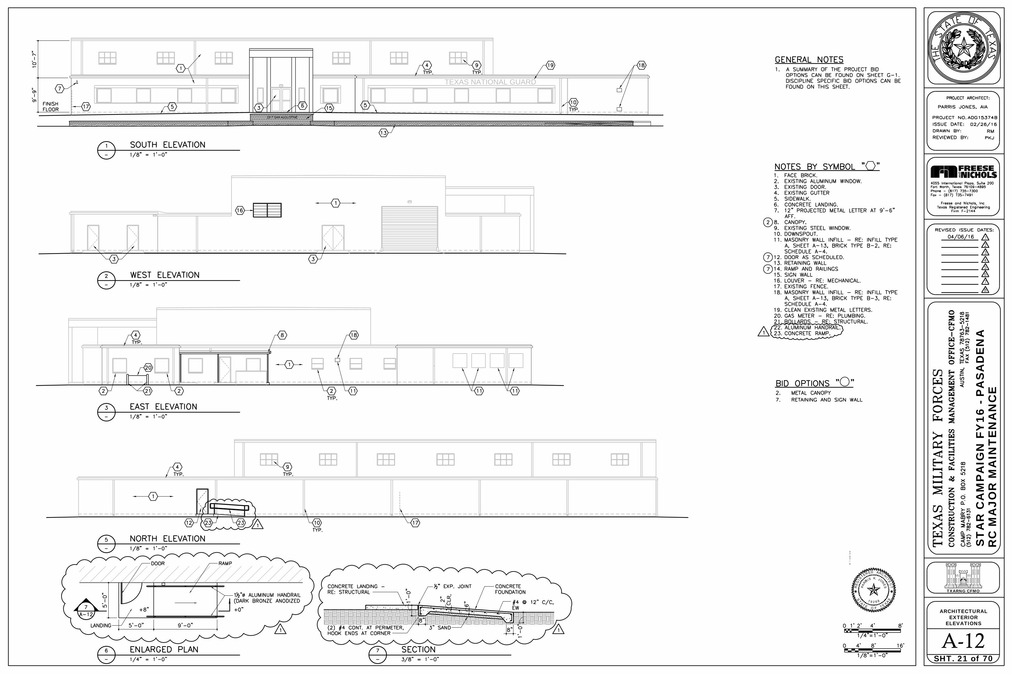
TEXAS NATIONAL GUARD1
RC
MA
JOR
MA
INT
EN
AN
CE
ST
AR
CA
MP
AIG
N F
Y16
- P
AS
AD
EN
A
TXARNG CFMO
70
ELEVATIONSEXTERIOR
A-12SHT. 21 of
ARCHITECTURAL

RC
MA
JOR
MA
INT
EN
AN
CE
ST
AR
CA
MP
AIG
N F
Y16
- P
AS
AD
EN
A
TXARNG CFMO
70
.ENLARGED PLANS
A-14SHT. 23 of
ARCHITECTURAL
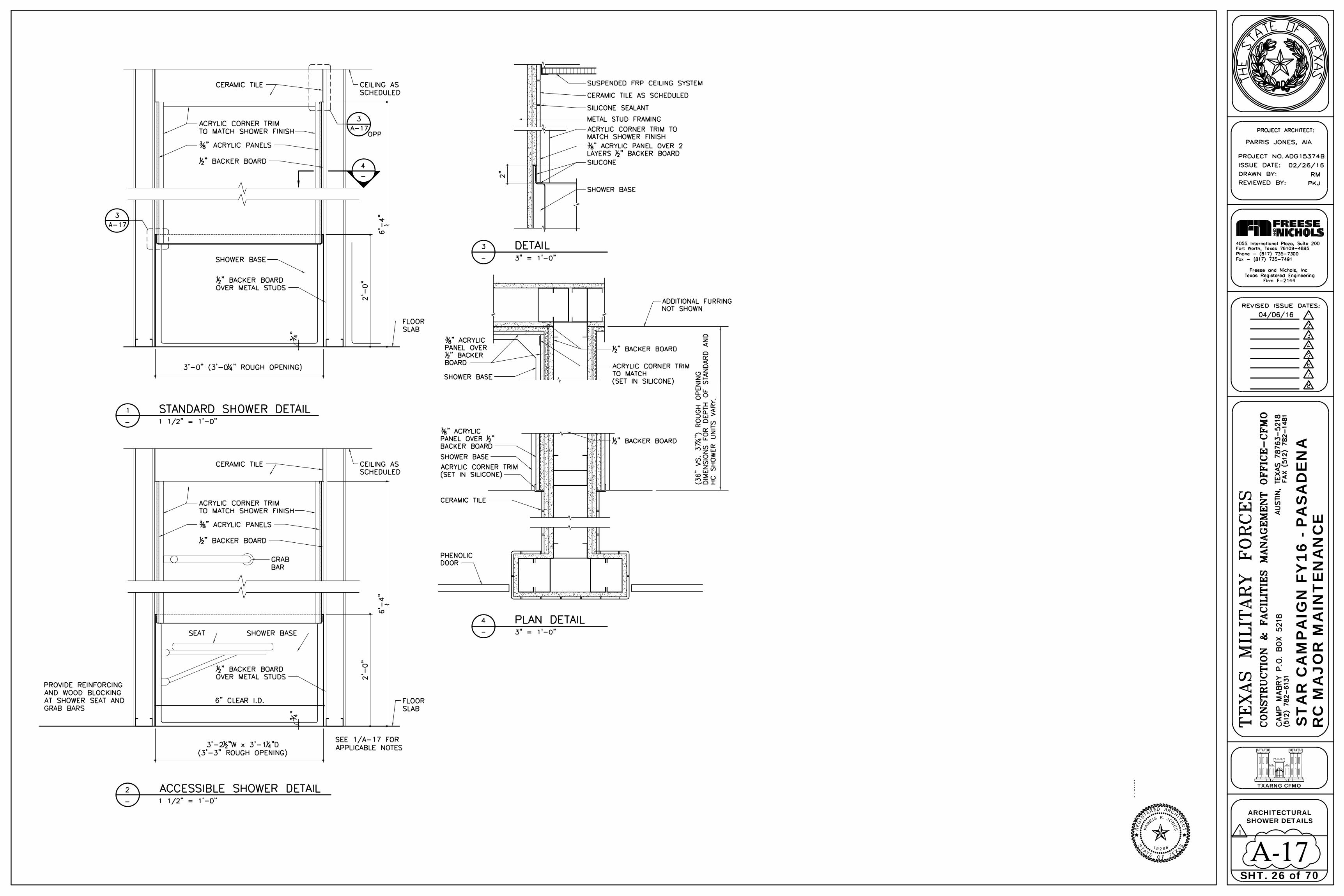
RC
MA
JOR
MA
INT
EN
AN
CE
ST
AR
CA
MP
AIG
N F
Y16
- P
AS
AD
EN
A
TXARNG CFMO
70
SHOWER DETAILS
A-17SHT. 26 of
ARCHITECTURAL
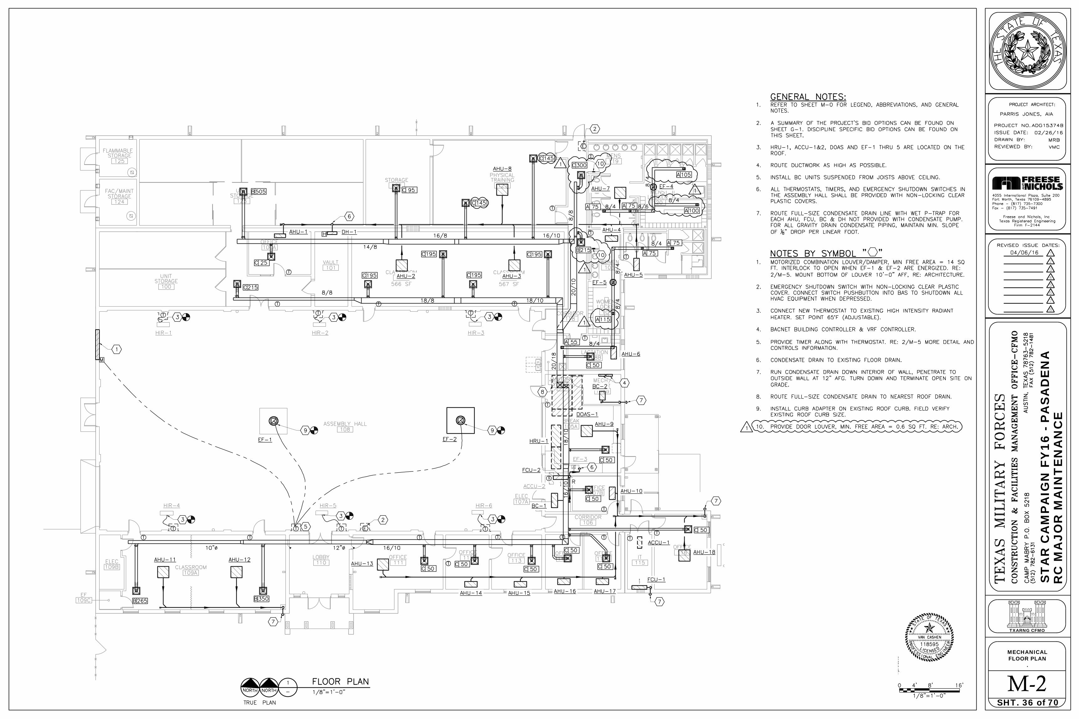
RC
MA
JOR
MA
INT
EN
AN
CE
ST
AR
CA
MP
AIG
N F
Y16
- P
AS
AD
EN
A
TXARNG CFMO
70
.FLOOR PLAN
M-2SHT. 36 of __
MECHANICAL

RC
MA
JOR
MA
INT
EN
AN
CE
ST
AR
CA
MP
AIG
N F
Y16
- P
AS
AD
EN
A
TXARNG CFMO
70
SCHEMATICSP&ID CONTROL
M-5SHT. 39 of __
MECHANICAL

PLAN
E-2SHT. 48 of __
ELECTRICAL
RC
MA
JOR
MA
INT
EN
AN
CE
ST
AR
CA
MP
AIG
N F
Y16
- P
AS
AD
EN
A
TXARNG CFMO
70

E-5SHT. 51 of __
ELECTRICAL
RC
MA
JOR
MA
INT
EN
AN
CE
ST
AR
CA
MP
AIG
N F
Y16
- P
AS
AD
EN
A
TXARNG CFMO
70

RC
MA
JOR
MA
INT
EN
AN
CE
ST
AR
CA
MP
AIG
N F
Y16
- P
AS
AD
EN
A
TXARNG CFMO
70
ELECTRICAL ROOM
E-7SHT. 53 of __
ELECTRICAL

RC
MA
JOR
MA
INT
EN
AN
CE
ST
AR
CA
MP
AIG
N F
Y16
- P
AS
AD
EN
A
TXARNG CFMO
70
HVAC POWER PLAN
E-9SHT. 55 of __
ELECTRICAL
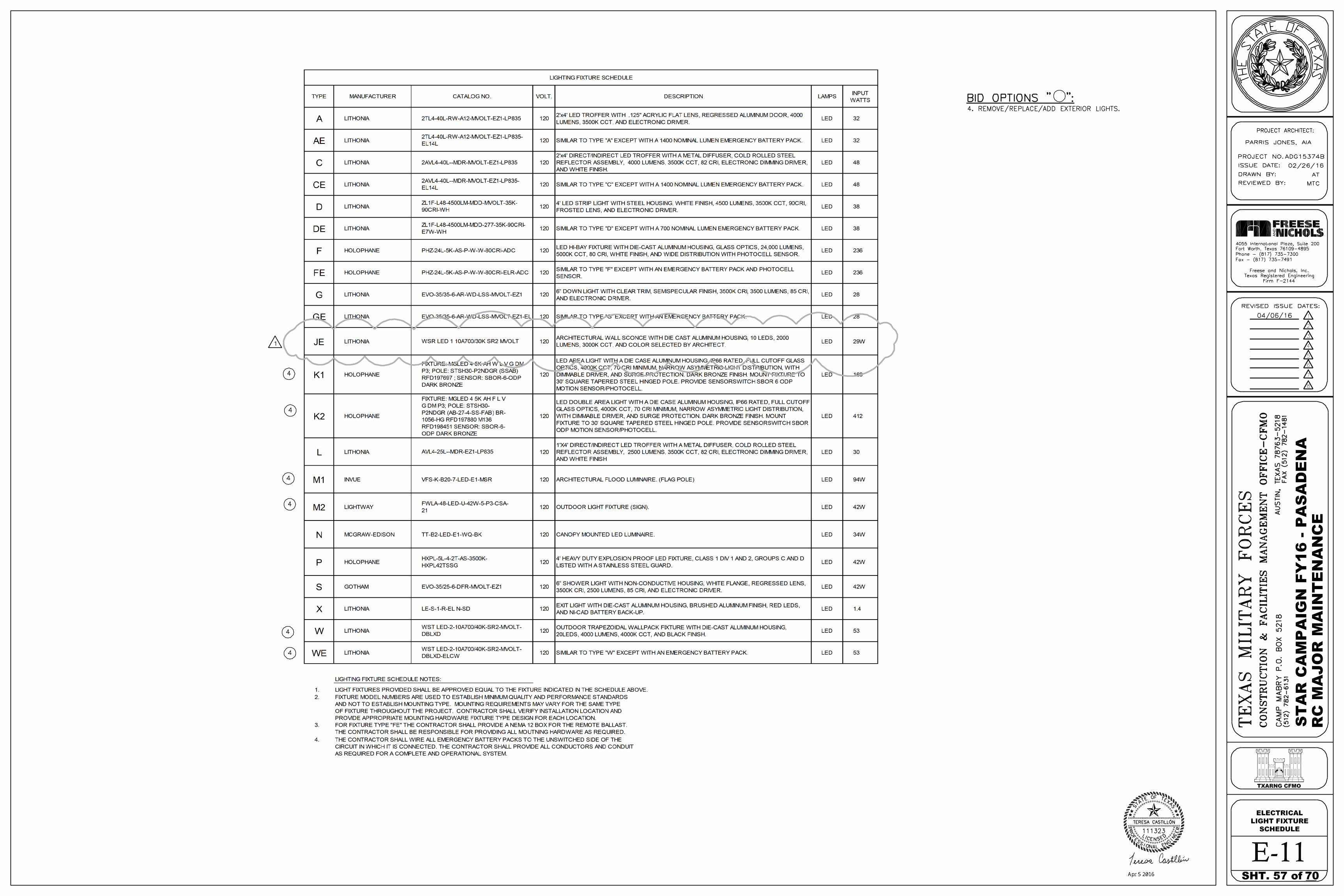
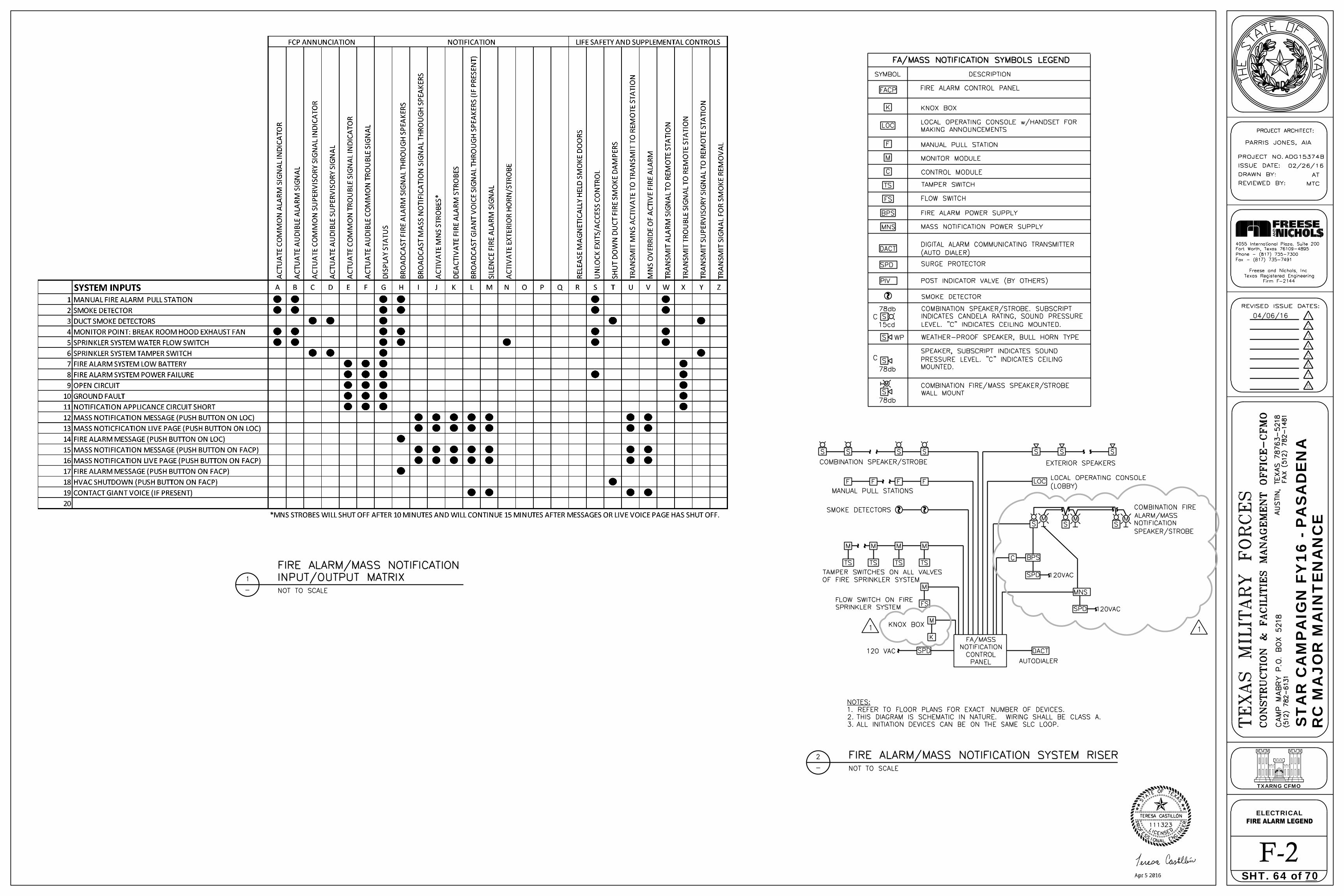
F-2SHT. 64 of __
ELECTRICAL
RC
MA
JOR
MA
INT
EN
AN
CE
ST
AR
CA
MP
AIG
N F
Y16
- P
AS
AD
EN
A
TXARNG CFMO
70

TECHNOLOGY PLAN
T-1SHT. 68 of __
ELECTRICAL
RC
MA
JOR
MA
INT
EN
AN
CE
ST
AR
CA
MP
AIG
N F
Y16
- P
AS
AD
EN
A
TXARNG CFMO
70