Embed Size (px)
Citation preview
NASA Technical Memorandum 104075
>.t _'77.....< ,-;;7 /+ ]/
1
BRAZE ALLOY PROCESS AND STRENGTH
CHARACTERIZATION STUDIES FOR 18 NICKEL
GRADE 200 MARAGING STEEL WITH
APPLICATION TO WIND TUNNEL MODELS
James F. Bradshaw, Paul G. Sandefur, Jr., and Clarence P. Young, Jr.
MAY 1991
..... -. ) +_}
++:_,+tg:; +++.+ _+. • ._:+,,.._ ,,z
_J
,b
National Aeronautics andSpace Administration
Langley Research CenterHampton, Virginia 23665-5225
https://ntrs.nasa.gov/search.jsp?R=19910015969 2018-07-28T21:19:20+00:00Z

1L
In Memorium
This paper is dedicated to Mr. James F. Bradshaw who passed away on September 7, 1986.
Mr. Bradshaw was a senior design engineer in the Model Engineering Section, Aeronautical
Systems Branch, Systems Engineering Division. This paper documents one of his many
contributions to the development of engineering design technology for cryogenic wind tunnel
model systems.

CONTENTS
Lists of Tables and Figures ............................ iv
Summary ................................... 1
Introduction• " • " ........ • • • _ .................. 1
Shear Test Specimens .............................. 3
Brazing Procedure..... ° ......................... 4
Test Procedure.................................
Shear Strength Test Results...........................
Temperature Management ............................ 6
Pressure Tube Installations• ........................... 7
Discussion of Results................. .......... • * ° 8
Conclusions..................................
References.................................. 10
Appendix A. Cleaning Procedures for Unplated Parts Used in the BrazingOperation .................................. 11
Appendix B. Procedures for Cleaning and Electroless Nickel Plating of18 Ni 200 Grade Maraging Steel ............. ........... 12
Appendix C. Brazing Processes for Various Alloys ................ 15
Appendix D. Effect of Braze Temperature on Charpy Impact Properties of18 Ni 200 Grade Mararging Steel
........................ 17
e t
111
_L.,,._.,_ffilE_ITI011/),I_I I1_ PRL::_CEDING PAGE BLANK NOT FILMED
List of Tables and Figures
Table D-I
Table I
Table II
Table III
Table IV
Figure 1
Figure 2
Figure 3
Figure 4
Figure 5
Figure 6
Figure 7
Figure 8
Figure 9
Figure 10
Figure 11
Figure 12
Figure 13
Figure 14
Figure 15
Figure 16
Figure 17
Charpy impact properties for 18 Ni grade 200 maragingsteel specimens for standard heat treatment and vacuum
furnace brazing cycles
Braze alloy specimens shear test results--single shear
Braze alloy specimens shear test results--double shear
Summary of braze alloy double shear test results givingaveraged values at room and -300°F temperatures
Summary of braze alloy single shear specimen test results
giving averaged values at room and -300°F temperatures
Plate geometry for shear specimens
Structural assembly for shear specimen
Illustration of brazed assembly usedfor shear specimens
Various shear specimens used for brazealloy tests
Illustration of placement of brazespecimens in furnace
Photo of test specimen in cyrogenic chamber on Instrontest machine
Shear strength properties for 18 Ni grade 200 steelbraze specimens
Failure surfaces for specimen number 10-2
Failure surfaces for specimen number 10-5
Failure surfaces for specimen number 12-4
Failure surfaces of specimen number 13-4
Example of displacement versus load for double brazeshear specimen 12-4 @ R.T.
Half-fuselage structure for the X-29
model wing
Photo illustrating end view of placement of stainlesssteel shields around thermal mass model of X-29
Perspective view of )(-29 thermal massmodel inside stainless steel shields
End view of X-29 thermal model invacuum braze furnace
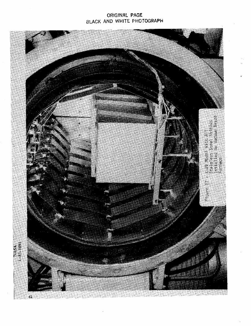
X-29 model with all stainless steel shieldsinstalled in vacuum braze furnace
iv
SUMMARY
A comprehensive study of braze alloy selection process and strength characterization with
application to wind-tunnel models is presented. The applications for this study include the
installation of stainless steel pressure tubing in model airfoil sections made of 18 Ni 200 grade
maraging steel and the joining of wing structural components by brazing. Acceptable braze
alloys for these applications are identified along with process, thermal braze cycle data and
thermal management procedures. Shear specimens are used to evaluate comparative shear
strength properties for the various alloys at both room and cryogenic (-300°F) temperatures
and include the effects of electroless nickel plating. Nickel plating was found to significantly
enhance both the wetability and strength properties for the various braze alloys studied.
The data provided in this paper are provided for use in selecting braze alloys for use with
18 Ni grade 200 steel in the design in wind-tunnel models to be tested in an ambient or
cryogenic environment.
INTRODUCTION
The use of braze materials for pressure tube installation and joining of structural members
for wind-tunnel models to be tested in a cryogenic environment has raised a number of
questions with regard to alloy selection, processing and strength. This paper presents
results of developmental work performed at the NASA Langley Research Center (LaRC)
to address these questions. In particular, this work investigated the use of braze materials
for installation of 347 stainless steel tubes in airfoils constructed of 18 Ni 200 grade maraging
steel and joining of wing structural members made of 18 Ni 200 grade steel.
The results presented herein were directly applicable to two wind tunnel models which
have been constructed for testing in the National Transonic Facility at LaRC. These were a
.0625 scale model of the forward swept wing X-29A and a .05 aeroelastically scaled model
of the F-111 TACT aircraft. Both models will be tested at full scale Reynolds numbers.
Of particular significancewas the F-111 model application. The wings on this model
weredesignedto havethe sametorsional and bendingpropertiesas the flight vehicle. To
accomplishthis, the wings were a stressedskin designwith spanwisespars, reinforcing
stringers and chordwiseribs. The right wing had pressureorifices. The fabrication plan
required that the internal shapeof the wing's upper and lower halvesbe finish machined
and the tubing brazedin place. The halveswerethen assembled,brazedtogether and the
external aerodynamicshapehand finished. This required a two phasebrazingprocesswith
the tube brazing material having a higher melt temperature than that used to braze the
wing halvestogether.
In addition to the melt temperature, there were two other important properties that
had to be consideredin selecting the braze material. Thesewere the shear strength of
the brazejoint, and the wetting propertiesof the braze material on the two metals to be
brazed. The F-111model structural material was 18 Ni grade200 maraging steeland the
pressuretubing was347stainlesssteel.The wetting property wasthe primary concernfor the
pressuretube installation (the higher temperaturebraze operation) and the shearstrength
wasof primary importance for joining the model parts together. Sheartype specimenswere
selectedto evaluatethe strength of the variousbrazealloysmaterials at room and cryogenic
temperaturesand alsostudy the wetting properties.
This report presentsthe results of the study of five vacuum furnace braze materials
proposedfor brazing stainlesssteel tubes to 18 Ni grade200 and brazing 18 Ni grade 200
parts together. The useof nickel plating to enhancethe wetting and strength propertiesof
brazematerials is alsodiscussed.
2
SHEAR TEST SPECIMENS
The primary objective in designing the test specimens was to produce a braze joint similar
to the geometry used in wind-tunnel model construction. This was accomplished by designing
a 6.5 inch long lap joint type structure (see fig. 1) from which specimens were made and
tested. It was believed that these specimens would closely represent the structural properties
of a joint similar to the one used to connect the F-111 model wing halves together.
The shear test specimens were made by brazing two 6.5 inch by 4.5 inch plates together
using two .62 inch wide splice plates (one splice plate for single shear specimens) and the
test braze material. This produced a 6.5 inch wide by 9.1 inch long assembly with four (4)
.25 inch lap shear surfaces (see fig. 2) for double shear specimens and two (2) .25 inch lap
shear surfaces for single shear specimens. After brazing and heat treatment, the assembly
was divided into five (5) equal pieces along the 6.5 inch dimension (see fig. 3). Each piece
was labeled with specimen number and part identification, 1 through 5. The specimens
were then machined to the required shape (see fig. 4). The overlap dimension for each shear
surface was measured and the shear area calculated. For each braze material two sets of
specimens were made, one electroless nickel plated on the braze surfaces and the other set
unplated.
The five braze materials studied (see table I) were:
BAg 21-63 Ag 28.5 Cu 6 Sn 2.5 Ni,
BAg 13-A-56 Ag, 42 Cu, 2 Ni,
BAg 8 (BT)-72 Ag 28 Cu,
Engaloy* 491-58 Ag, 32 Cu, 10 Pd, and
BAU-4-82 Au 18 Ni.
* Use of trademarks or names of manufacturers in this report does not constitute an official endorsement of such products or
manufacturers, either expressed or implied, by the National Acronautics and Space Administration.
3
BRAZING PROCEDURE
The brazing was done in a vacuum furnace. Thermocouples were spot welded to each
part to be brazed and the temperatures were monitored to assure that all parts reached
the required temperature. The unplated parts were cleaned using the cleaning process
described in appendix A. The nickel plated parts were cleaned and plated using the process
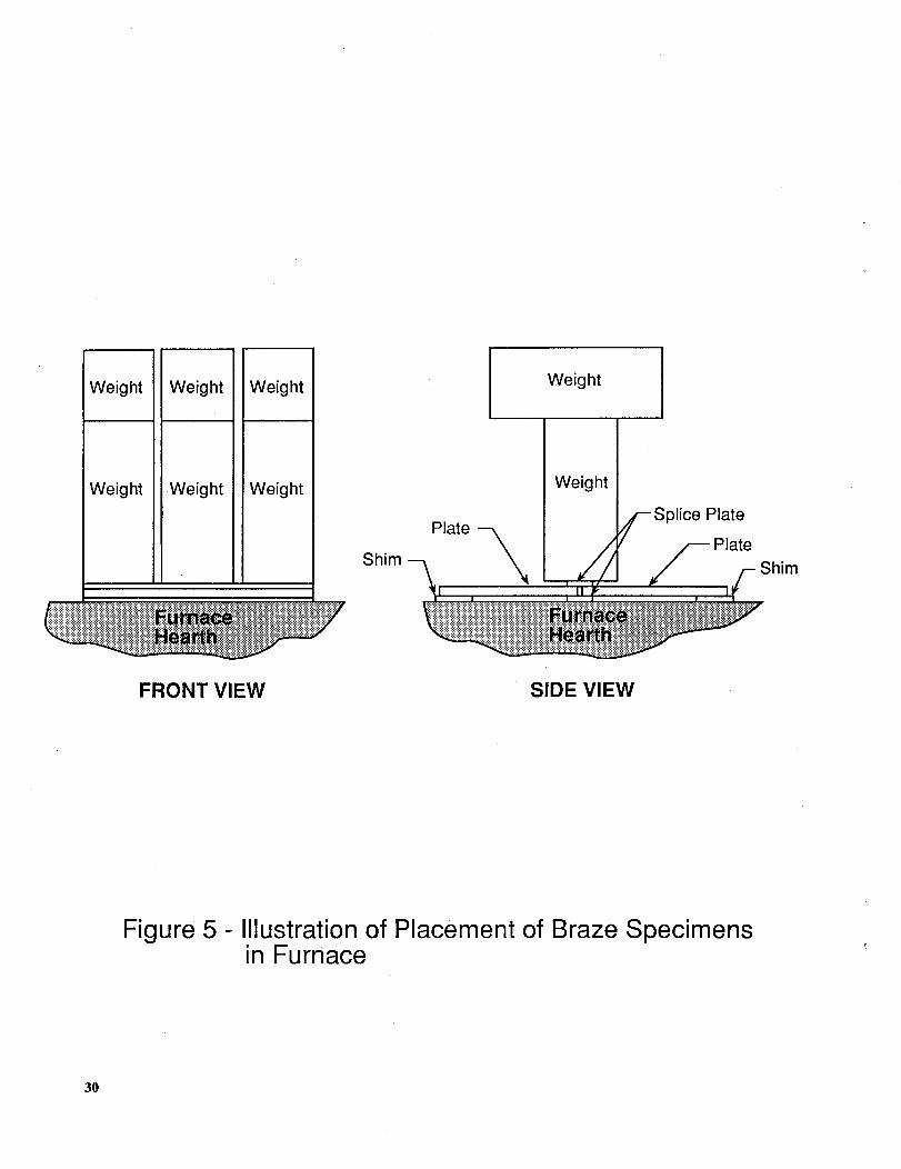
in appendix B. A 32-pound weight consisting of six 2-inch x 2-inch × 4.75-inch steel blocks
equally spaced (see fig. 5) was placed on the top splice plate to provide a uniform force to
the splice plate during heating. The brazing cycles used for the specified brazing materials
are given in appendix C.
TEST PROCEDURE
The test program consisted of applying a tensile load until failure occurred. Testing was
done at room temperature (70°F) and at cryogenic temperature (-300°F). Tensile load and
specimen elongations were measured. For the cryogenic test, (see fig. 6) the environmental
chamber on the Instron load tester was cooled to -300°F and the specimen allowed to soak
to obtain a uniform temperature throughout the setup. The designated numbers 1 and 4
specimen in each assembly were tested at room temperature and designated numbers 2 and
5 specimen were tested at cryogenic temperature. The number 3 specimens were kept for
possible future testing. See figure 3 for illustration of specimen numbering system.
SHEAR STRENGTH TEST RESULTS
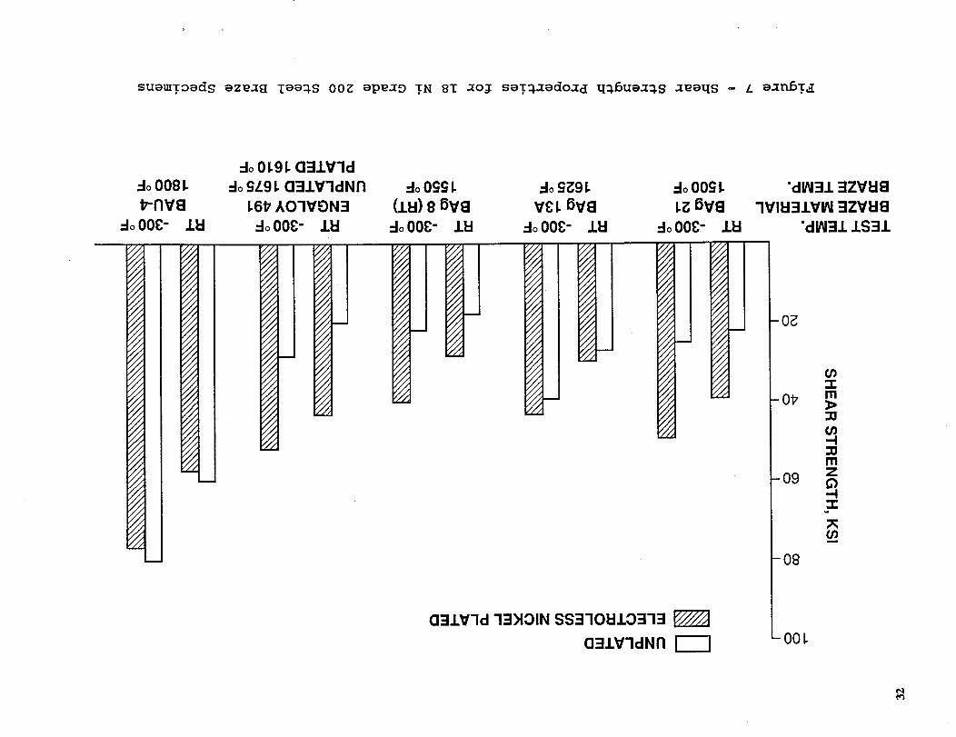
The test results (see fig. 7) show that the shear strength of all materials increased at
-300°F (cryo temp.) compared with the room temperature strength. Also, with the
exception of the BAU-4 material (which had excellent, indicated shear strength with or
without plating after grain refinement), the electroless nickel plating improved the shear
strength of the joint. The BAU-4 material was by far the strongest braze material. The
4
BAg 8 (BT) produced the lowest strength joint. The specimen shear areas were sized based
on anticipated shear strength and loading limitations of test equipment (see fig. 4).
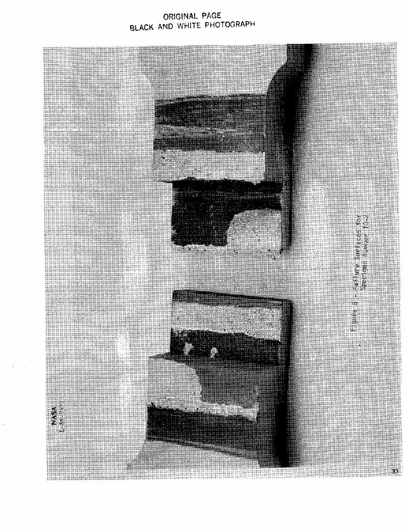
A review of the test results (tables I and II) for the limited number of specimens show
that the results of similar specimens tested at the same temperature may vary by several
thousand psi or of the order of :t=10%. For example, in table II, double shear specimens
10-2 and 10-5 were made from the same assembly of a double shear unplated Engaloy 491
braze joint. The failure shear stress (based on overlap run) of 10-2 was 28,042 psi and 10-
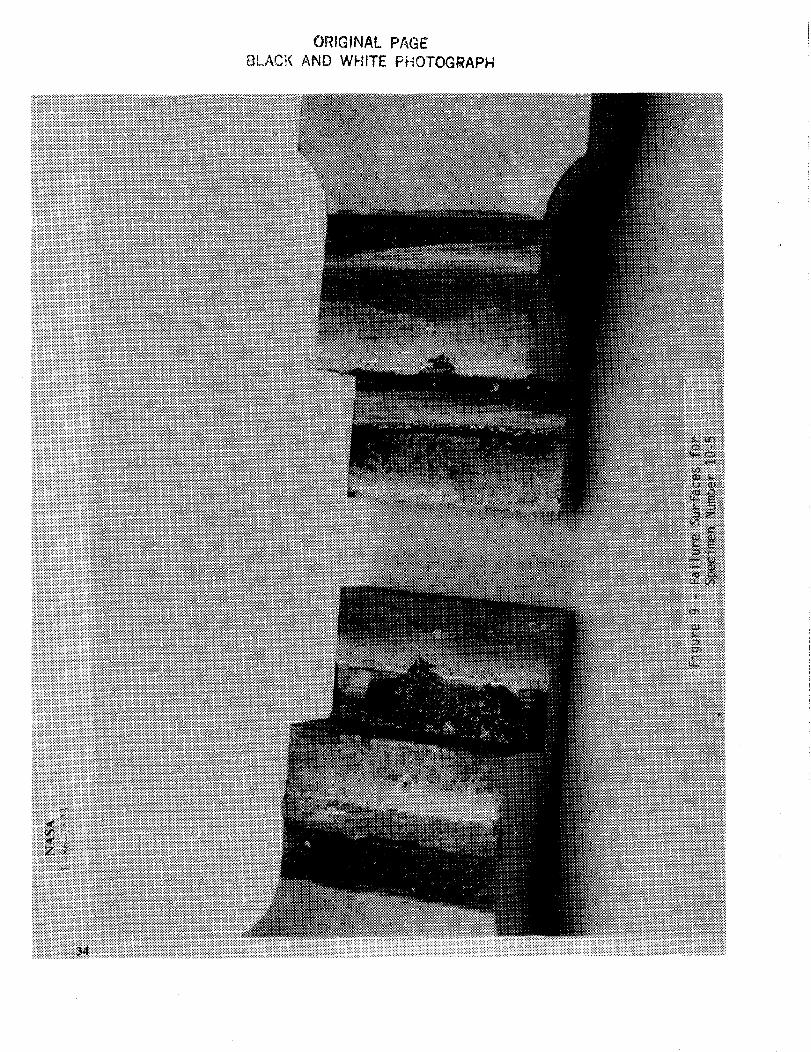
5 was 31,763 psi at -300°F. An inspection of the braze surfaces, see figures 3, 8, and 9,
clearly shows that the higher strength 10-5 specimen had a larger area of braze material than
specimen 10-2, which suggests the importance of the wetting property of the braze material.
There was no attempt in this study to measure the actual wetted area of the brazed joint,
i.e., the area on the shear surface that had been joined by the braze material. All shear
stress calculations were based on the idealized overlap area for a perfect braze joint.
As previously stated, all stresses were calculated using the overlap area of the splice plate.
In cases where several shear surfaces failed, the larger areas on opposite sides were used to
calculate the failure stress which is a conservative approach. As an example, specimen
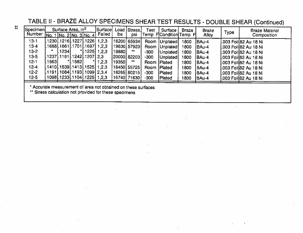
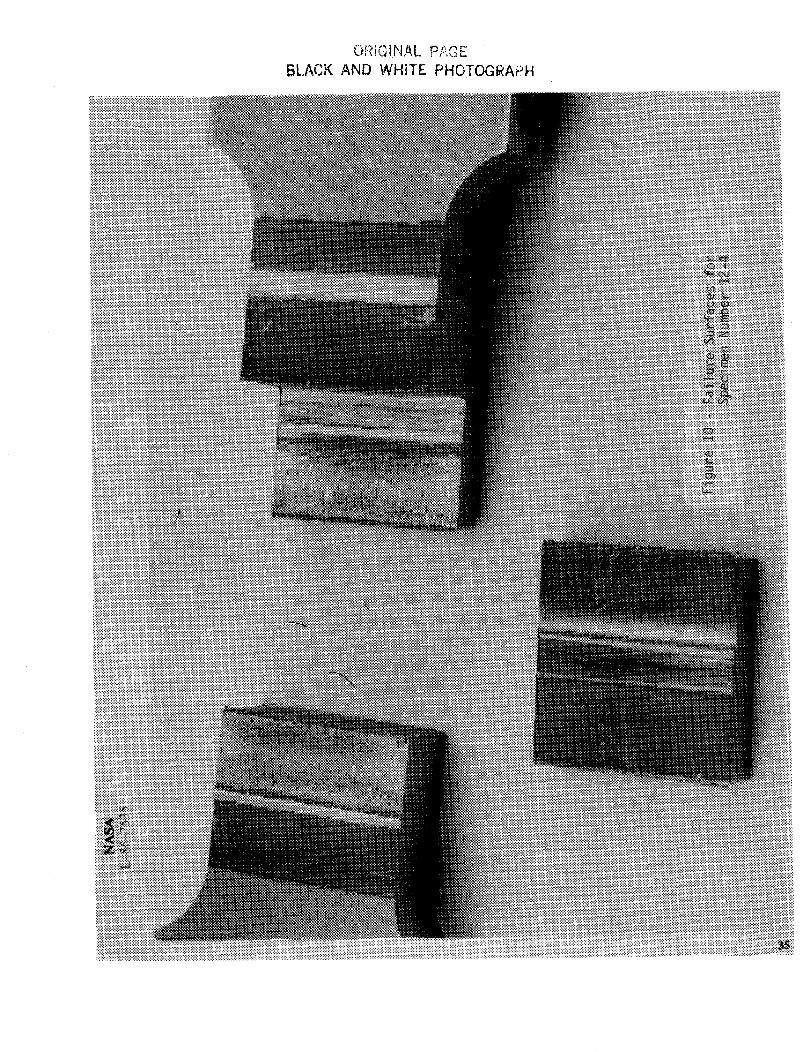
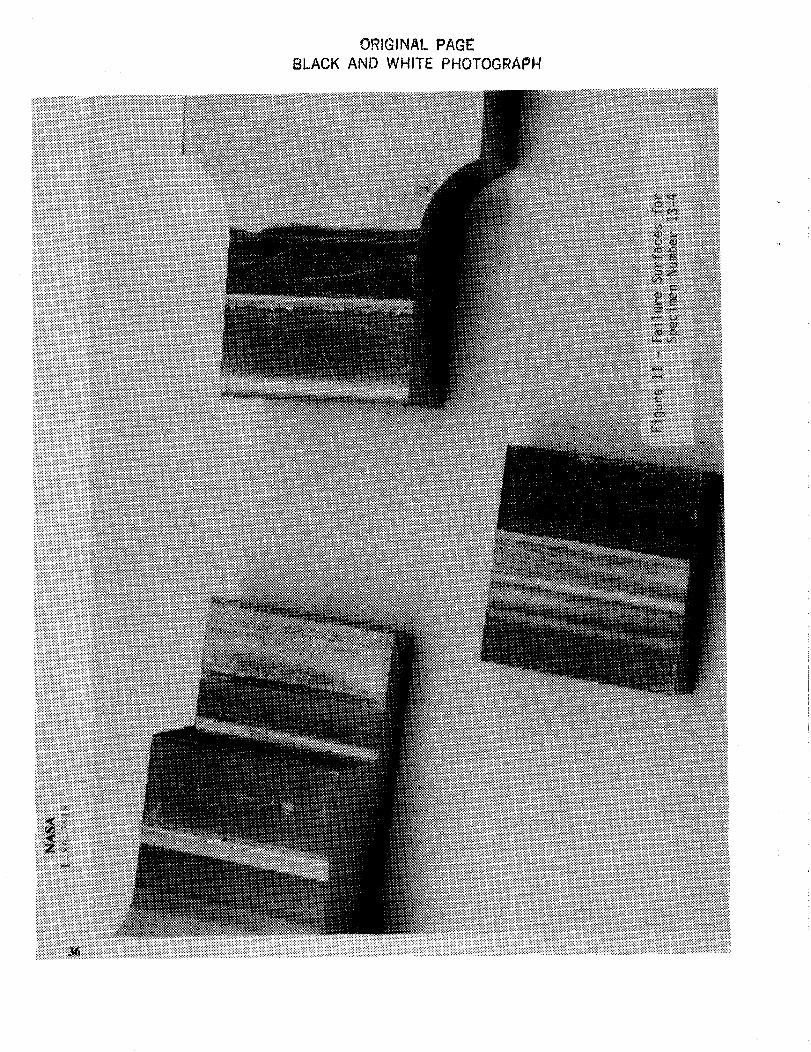
number 12-4, see figure 10, had a failure of surfaces 1, 2, and 3. The stress was calculated
using the sum of area 1 and 3. But in the case of specimen 13-4 (see fig. 11) the area of
surface 2 and 3 was used.
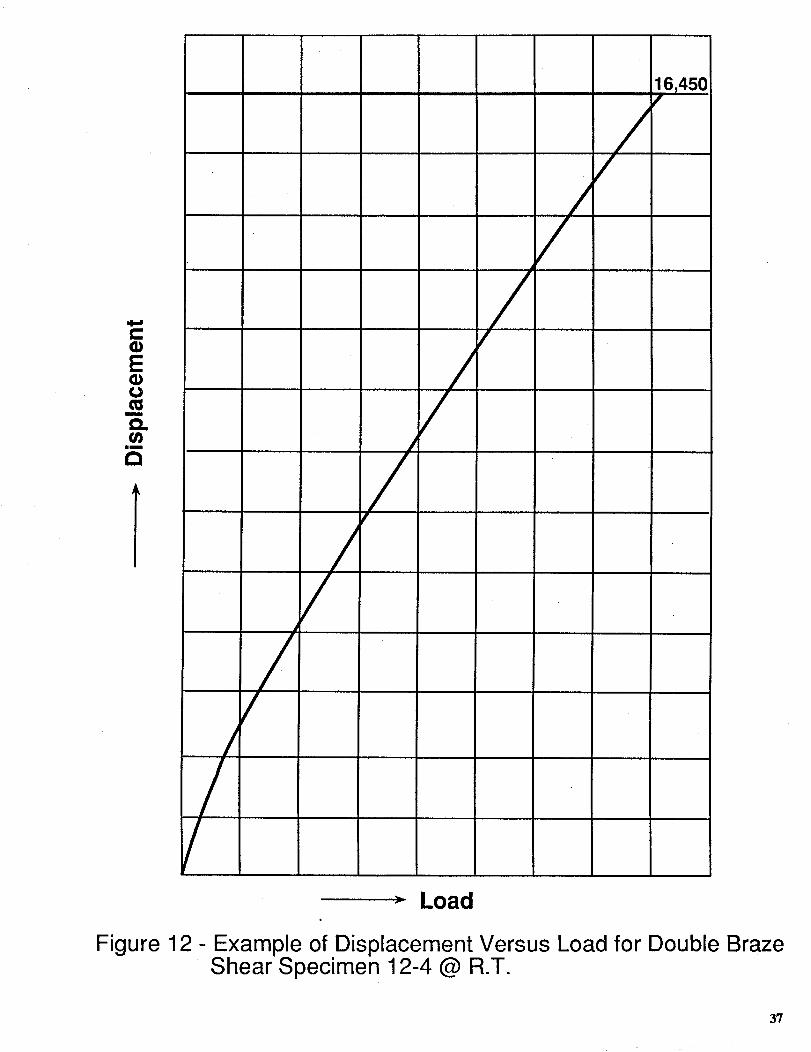
A review of the strip charts shows that all specimens behaved similar in that elongation
was essentially linear until failure of the brazed joints (see fig. 12). The single shear specimens
consistently failed at a lower stress level than the corresponding double shear specimens. This
is attributed primarily to the design of the single shear specimen (see fig. 3) which have the
shear surfaces off center, producing a combination of shear and peel stresses on the brazed
joint. Therefore, these results are not valid as pure shear data but it is anticipated that the
actual shear strength would be higher given the absence of peel type loading.
5
The averagedshearstresslisted in table III and figure 7, for the doubleshearspecimens,
may beusedasa criteria for the designof sheartype joints in 18Ni 200grademaragingsteel
models. A moreconservativeapproachwould be to usethe minimum valuestaken from the
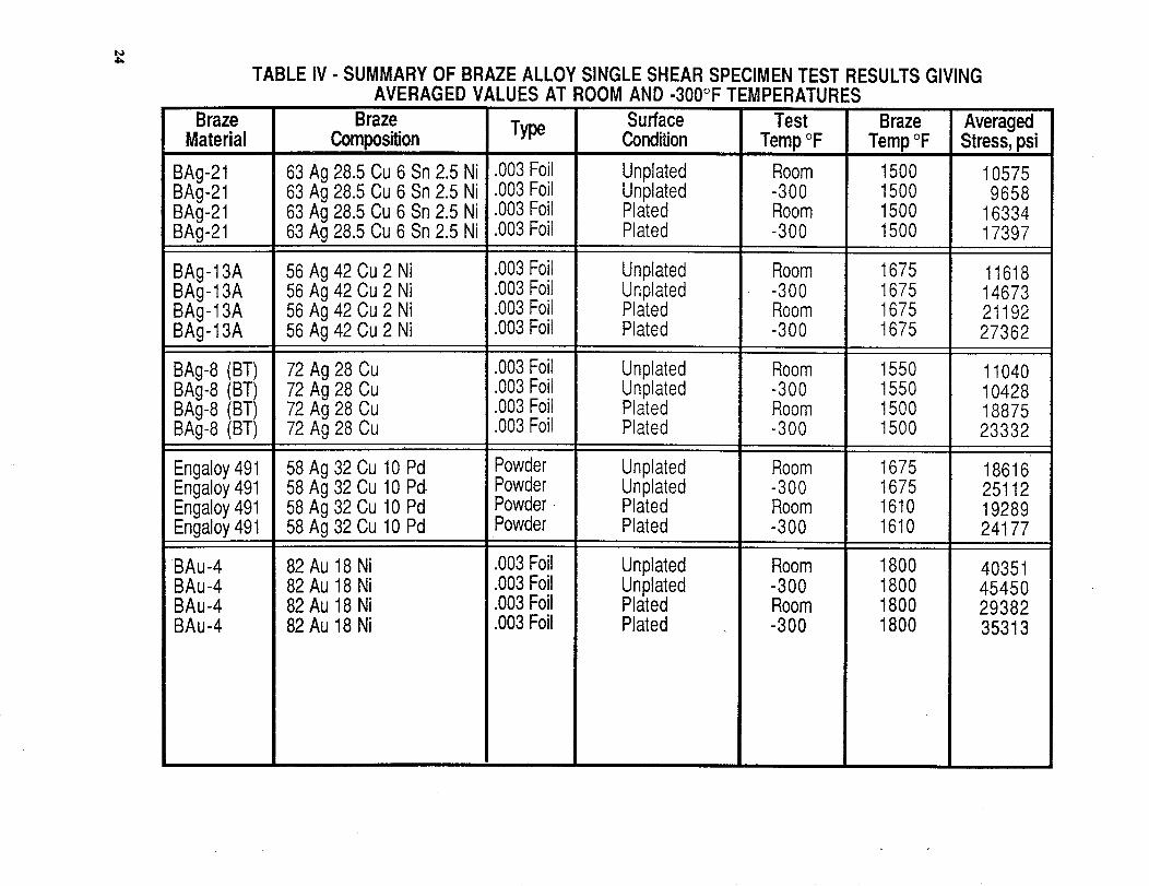
data in table II. The data for the singlesheartests in tables I and table IV providea basis
for designallowableshearwhich may be usedfor brazejoints that haveboth shearand peel
type loadspresent.
TEMPERATURE MANAGEMENT
Proper control of the temperature gradient through the model part is critical when
vacuum brazing either pressure tubing or structural joints. For example, many parts are
rough machined to oversize prior to the brazing process and' may have a large mass such as
a fuselage and a thin plate shape for wings. When this assembly is placed in a furnace the
thin plate shape will heat up much faster than the fuselage mass with possible distortion
occurring due to temperature gradients. Therefore, a system must be developed to control
the heating rate of the various model surfaces. This type of problem had to be solved before
the pressure tubes could be brazed in the NTF X-29 wind tunnel model wings.
The actual part consisted of a half fuselage wing structure (see fig. 13) rough machined
to shape. A thermal mass model of this part was made using square bars and plates to
simulate the actual model fuselage configuration. Thermocouples were spot welded to the
bars and plates and the mass model was then used to develop a procedure for controlling
the temperature gradients in the actual model as described in the following paragraphs.
The heating of the model part was controlled by placing a 347 stainless steel (.032 inch
thick) sheet around the model (see figs. 14 and 15). A larger box shape shield, made of 347
stainless steel, was placed over the first shield (see figs. 16 and 17) to produce a 2-inch gap
between the two shields. A Q-felt insulation material was then placed between the model
and the furnace hearth. Using this system the heating of the thinner areas of the model
could be controlled to an acceptable rate.
6
PRESSURE TUBE INSTALLATION
Langley has made extensive use of vacuum furnace brazing as a method of installing
pressure tubing in all types of models. Experience has demonstrated that selection of the
braze alloy should be based on parent material temperature limitation, types of materials
to be joined, the joint configuration and the parts configuration. The liquid temperature of
the braze material should never be the only consideration for this selection.
A typical problem encountered in brazing a 347 stainless steel tube to 18 Ni maraging steel
is that the high Chromium metals such as 300 series stainless steels are generally difficult to
wet at temperatures below 1800°F. The BAU-4 (gold nickel) alloy with an 1825°F brazing
temperature is a good braze material if the part configuration (e.g., highly contoured thin
section) can endure the high temperature without altering the material microstructure and
hence the material properties, and without significant distortion.
For conditions requiring a temperature to be less than 1700°F, the use of electroless
nickel plating of both the model part and the 347 stainless steel tubing improved the wetting
properties of BAg 13-A, BAg 21, and Engaloy 491 braze material. It should be pointed out
that care should be taken to avoid scraping the nickel plating off either part.
A prime consideration for using two step brazing is to use BAU-4 (gold nickel, 1825°F
temperature) followed by Engaloy 491 (1610°F temperature) because the 1610°F tempera-
ture can serve as a grain refinement process which tends to improve the charpy properties
of the 18 Ni 200 grade material at -300°F (see appendix D).
Another consideration for wind tunnel pressure models application is to use phosphorus
deoxidized copper tubing (copper alloy number 122) and Engaloy 491 braze material which
has a 1610°F braze temperature. This copper alloy is acceptable for cryogenic use. Also for
a two phase brazing process, the first braze cycle can be with the Engaloy 491 (1610°F) with
BAg 21 (1500°F) as the second braze.
During a subsequent study related to pressure tube installation it was observed that thin
sections of 18 Ni 200 grade maraging steel, which had metal removed by electric discharge
7
machining (EDM), distorted (oil canned)significantly during the brazing operation. Al-
though the maragingsteelhasgenerallygooddimensionallystability it appearsthat caution
should be exercisedwhen heat treating thin sections (i.e., 0.60 or less) that have EDM
surfaces.
DISCUSSION OF RESULTS
The shear specimens used in this study were designed to represent a typical braze joint
that may be used in model construction. In most models, the braze joint is used to join parts
together to produce a monolithic-type structure. Most of these joints are internal or in a
position that they cannot be inspected to evaluate the quality of the braze joint. The design
of the test specimens using a 6.5 inch long braze joint and the selection of the specimens
positioned along this joint was done to provide some measure of the strength of a long brazed
joint. Because of the limitation of this test program the effects of the presence of tensile
stresses in the specimen on the shear stress capability in the brazed joint are unknown.
Also since the number of specimens were limited, a more meaningful measure of mean and
dispersion failure stresses cannot be obtained. Therefore, minimum values are recommended
for use in design.
The mechanism by which the electroless nickel plating enhances the wetting and strength
properties of the brazed joint is not clearly understood. It may be that the plating process
results in exceptionally clean, well prepared surfaces which are more difficult to achieve
without plating. Another possibility is that the diffusion of the nickel plating material into
the parent material provides a metallurgically altered surface which enhances both flow
and adherance properties. However, good enhancement provided by nickel plating for this
material may not work for other materials.
The wetting properties of the braze alloy is of primary importance for pressure tube
installation. The liquid temperature of the braze material must be considered to assure
that it is within the allowable temperature range for the model and tubing materials.
8
The temperature is critical for a two step brazing process such as that required for the
F-111 model. However, good wetting properties of the braze alloy are needed to produce a
leak-proof joint between the tube and the model. LaRC has had excellent results using the
BAU-4 (gold nickel) braze alloy (1825°F brazing temperature) to install 347 stainless steel
tubing in 18 Ni 200 grade model material. The use of electroless nickel plating to enhance
the wetting properties of BAg-13A, BAg 21, and Engaloy 491 has produced good results in
pressure tube installation. Another acceptable approach to tubing installation would be to
use phosphorus deoxidized copper tubing (copper alloy number 122) with the Engaloy 491
braze alloy.
There is a potential problem of grain growth in 18 Ni 200 grade material when exposed to
high temperatures (see reference 1). The 1825°F melt temperature of the BAU-4 braze alloy
can result in an unacceptable grain growth condition that lowers toughness and strength
which, based on LaRC experience, can be corrected by following the high temperature braze
cycle with a 1610°F cycle prior to final heat treatment of the material (see appendix D).
Tests conducted in support of this study show that the temperature cycle of 1825°F, air cool,
1610°F, air cool, and 900°F 3 hrs. air cool allows recovery of fine grain structure. Alteration
of parent material microstructure is a primary consideration when selecting single or dual
temperature braze systems.
CONCLUSIONS
Based on the results of these studies the following conclusions were obtained:
1. A number of braze alloys were found to be suitable for use in wind-tunnel models
constructed of 18 Ni grade 200 steel.
2. Electroless nickel plating of the surfaces to be brazed significantly enhances both
wetability and shear strength properties.
9
3. The shear strength properties presented in this paper provide a basis for
determining design allowable values. It is recommended that minimum shear strength values
be used.
4. Thermal management of vacuum furnace brazing cycles is needed to assure a
more uniform heating of model parts having significant differences in thermal mass, thereby
enhancing the braze process.
5. Brazing cycles should be established such that the use of high temperature braze
alloys will not significantly alter the microstructure of the parent material which can lead to
reductions in strength and toughness properties.
6. The data provided in this paper can be used for brazing applications involving
18 Ni 200 grade steel and may be applicable to other materials as well.
REFERENCE
1. Rush, Homer F.: Grain-Refining Heat Treatments to Improve Cryogenic Toughness of
High-Strength Steels, NASA TM 85816,1984.
10
APPENDIX A
CLEANING PROCEDURES FOR UNPLATED PARTS USED
IN THE BRAZING OPERATION
A. Clean parts with greases, oils, marking dyes and inks with acetone or methyl ethyl ketone
(MEK).
1. Clean by hand, using bristle brushes (no wire brushes) and/or wipers.
B. Clean in a detergent until water will not bead.
1. Use 6 oz. Turco 4215 NC-LT, or equal, per gallon of water.
2. Place in deionized water at room temperature for 15 minutes minimum.
3. Rinse thoroughly in deionized water.
C. Emerse parts in liquid freon TF; use ultrasonic cleaning for 15 minutes.
D. Ultrasonics may heat parts enough to cause a discoloration (oxidation). If this happens
the cleaning procedure is repeated while making sure parts are not heated (kept cool or
at room temperatures). This is a problem on metals that oxide readily (maraging steels).
E. Allow to dry and then wrap in clean brown paper and put in plastic bag until ready to
put in vacuum furnace.
F. This cleaning procedure may be used on plated parts for removal of light contamination
due to handling.
11
APPENDIX B
PROCEDURES FOR CLEANING AND ELECTROLESS NICKEL
PLATING OF 18 Ni 200 GRADE MARAG1NG STEEL
All machining and center punching for braze alloy clearances must be completed prior
to beginning cleaning and plating. Any work that might remove plating in braze areas will
prevent braze flow.
1. Submerge in acetone and hand scrub using bristle brushes and cloth towels to remove oil
and dirt.
2. Vapor degrease in freon and ultrasonics.
a. Use Type I Mil. Spec. C-81302C Trichlorotrifluoroethane or equal.
3. Clean in a detergent until water will not bead.
a. Place in Turco 4215 NC-LT. 6 oz. per gallon of water. Place in deionized water at
room temperature for 15 minutes minimum.
4. Rinse in deionized water, thoroughly.
CAUTION
Once the work piece goes into the detergent bath it must not be dried at any stage until
it is plated--from detergent through plating is a continuous operation.
5. Place in Hydrocloric Acid Bath
59% Hydrochloric Acid--by volume
41% Deionized Water--by volume
70°C (158°F)
10 minutes 4-1 minute (Critical)
6. Rinse exceptionally well in deionized water
a. Pay special attention to areas where acid could be trapped.
7. Place in Nitric/Hydrofluoric Acid Bath
a. 50% Nitric Acid--by volume
10% Hydroflouric Acid--by volume
12
40%deionizedwater--by volume
Room temperature
10seconds-t-0seconds-1 second(Critical) rapid metal removal
8. Rinseexceptionallywell in deionizedwater
a. Pay special attention to areas where acid could be trapped.
9. Place in Hydrochloric Acid Bath
a. 59% Hydrochloric Acid--by volume
41% Deionized water--by volume
70°C (158°F)
5 minutes--maximum +0 minutes -1 minute
10. Rinse exceptionally well in deionized water
a. Pay special attention to areas where acid could be trapped.
11. Place in Electroless Nickel Plating Bath.
a. High Purity electroless nickel--manufactured by Shipley Company, Newton, Mass.
Niposit 468
Mix according to manufacturers specifications
Specs. furnished with material order
Suspend work piece in bath with stainless wire
Bath temperature is 158°F to 160°F
Plating will start when job reaches bath temperature
Bubble activity around job will signify when plating starts
Hold for 15 minutes to get approximately .000087 inch-thickness
Bath must be agitated during plating
Bath will plate 3 to 3 1/2 tenths of a mil per hour
Ph of bath to be 6.8 to 7.5
Purity of nickel is 99.5%
Hardness as plated is Rc 63
13
Melting point is 1455°C (2646°F)
Color Semi-Bright
Boron 0.25%
12. Rinse in Deionized water, THOROUGHLY.
13. Rinse in isopropanol (alcohol) and blow dry with clean air.
14. Wrap in clean brown paper and place in zip-lock type plastic bag until preparing for
brazing.
14
APPENDIX C
BRAZING PROCESSES FOR VARIOUS ALLOYS
The following processes were used for the brazing materials listed.
BAg 21-63 Ag, 28.5, Cu 6Sn, 2.5 Ni .003 thick foil
Plated and Unplated Specimens
Heat to 1425°F hold until all thermocouples read 1425°F =t=5°F
Heat to 1500°F hold 10 minutes
Vacuum cool to less than 300°F
Air cool
BAg 13A-56 Ag, 42 Cu, 2 Ni .003 thick foil
Plated and Unplated Specimens
Heat to 1600°F hold until all thermocouples read 1600°F =k 10°F
Heat to 1675°F hold 10 minutes
Vacuum cool to less than 300°F
Air cool less than 90°F
BAg 8 (BT)--72 Ag, 28 Cu .003 thick foil
Unplated Specimens
Heat to 1400°F hold until all thermocouples read 1400°F =t= 10°F
Heat to 1550°F hold 20 minutes
Vacuum cool to less than 300°F
Air cool
Plated Specimens
Heat to 1400°F hold until all thermocouples reach 1400°F + 10°F
Heat to 1500°F hold 10 minutes
Vacuum cool to less than 300°F
Air cool
15
ENGALOY 491-58 Ag, 32 Cu, 10 Pd powder
Unplated
Heat to 1475°F hold 20 minutes
Heat to 1675°F hold 10 minutes
Vacuum cool to less than 300°F
Air cool
Plated
Heat to 1475°F hold 20 minutes
Heat to 1610°F until all parts at equilibrium
Vacuum cool to less than 300°F
Air cool
BAU 4 (gold nickel)--82 Ag, 18 Ni .003 thick foil
The same process was used for both plates and unplated specimens.
Heat to 1650°F hold 20 minutes
Heat to 1825°F hold 4 minutes
Vacuum cool to less than 300°F
Air cool
Note: The vacuum furnace used cannot be opened to the atmosphere until the tempera-
ture is below 300°F
16
APPENDIX D
EFFECT OF BRAZE TEMPERATURE ON CHARPY IMPACT
PROPERTIES OF 18 Ni 200 GRADE MARAGING STEEL
A study of the effects of vacuum furnace brazing on the charpy impact properties at
cryogenic temperatures of 18 Ni 200 grade maraging steel has been completed. The results
are summarized in table D-1. This study consisted of cutting one piece of stock material into
several pieces. One piece went through the standard heat treatment of 900°F for 3 hours and
air cooled. The other pieces were heated in the vacuum furnace through the same brazing
cycle as would be used for model parts. This study showed that the material heated to 1825°F
followed by the 900°F 3-hour treatment has a lower charpy value at room and cryogenic
temperatures than the stock material which was likely due to excessive grain growth. The
material that was heated to 1825°F and reheated to 1610°F followed by the 900 ° 3-hour
heat treatment had about the same charpy value at room and cryogenic temperature as the
stock material.
17
TABLE D-ICIIARPY IMPACT PROPERTIES FOR 18 Ni 200 GRADE MARAGING STEEL
SPECIMENS FOR STANDARD HEAT TREATMENT ANDVACUUM FURNACE BRAZING CYCLES
Solution Annealed
gOO°F - 3 hrs.
Aircool
Tranverse
Cryo Room20 31
20 3420 3518 33
Average
19.5 33.2 I
@
Longitudinal
Cryo2223
2322
Room4444
4651
Solution Annealed
1650°F - 20 min.1825°F - 4 min.
22.5 46.2
AircoolgOO°F - 3 hrs.
Aircool
®
Transverse
Cryo Room14 2915 30
14 2814 28
Longitudinal
cryoIRoom
13 3716 4O
15 3617 38
Average
14.2 28.7 I 15.2 37.7
Solution Annealed (_)
1650°F - 20 min.1825°F - 4 min.
Aircool1475°F - 20 min.
1610°F - 10 min.AircoolgOO°F - 3 hrs.Aircool
Transverse
Cryo Room17 34
21 3218 3318 33
18.5
Longitudinal
Cryo Room22 47
22 4522 4922 49
Average
33 ] 22
Solution Annealed (_)
1650°F - 20 min.1825°F - 4 min.
Aircool1475°F - 20 min.
1610°F - 20 min.AircoolgOO°F - 3 hrs.
Aircool
Transverse
4/.5
Cryo162OIg
17
18
¸'Room35
.363433
Longitudinal
Cryo Room20 4422 42
22 4922 47
Average
34.5 I 21.545.5
NOTE: All charpy impact values are given in ft-lbs.
(_)- As received from mill.
(_)- Standard braze cycle for BAu-4 braze alloy.
(_)- Braze and grain refining cycle as developed at LaRC.
Q- Braze and grain refining cycle with grain refining cycle doubled.
Specimen Surface Area, in 2Number N_ 1 No.2
1-1 .2489 .23961-4 .2444 24191-2 .2484 .23991-5 2200 .21382-1 .1987 .20232-4 2455 25052-2 .2464 25052-5 .2449 .2490
TABLE I - BRAZE ALLOY SPECIMENS SHEAR TEST RESULTS - SINGLE SHEAR
Surface Load Stress, Test Surface Braze Braze
Failed I bs psi Temp °F Condition Temp °F Alloy Type
1 2800 11208 Room Unplated 1500 BAg-211 2430 9942 Room Unplated 1500 BAg-211 2450 9863 -300 Unplated 1500 BAg-211 2080 9454 -300 Unplated 1500 BAg-211 3160 15903 Room Plated 1500 BAg-212 4200 16766 Room Plated 1500 BAg-212 4390 17525 -300 Plated 1500 BAg-212 4300 17269 -300 Plated 1500 BAg-21
.003 Foil
.003 Foil,003 Foil.003 Foil.003 Foil,003 Foil,003 Foil,003 Foil
Braze Material
Composition
63 Ag 28.5 Cu 6 Sn 2.5 Ni63 Ag 28,5 Cu 6 Sn 2.5 Ni63 Ag 28.5 Cu 6 Sn 2.5 Ni63 Ag 28.5 Cu 6 Sn 2.5 Ni63 Ag 28.5 Cu 6 Sn 2.5 Ni63 Ag 28.5 Cu 6 Sn 2.5 Ni63 Ag 28.5 Cu 6 Sn 2.5 Ni63 Ag 28.5 Cu 6 Sn 2.5 Ni
3-1 2365 .24393-4 .2430 24503-2 2486 24093-5 .2374 .2454
16-1 .2440 .243916-4 .2449 245916-2 .2451 245016-5 .2439 .2462
1 2600 10993 Room Unplated 1675 BAg-13A2 3000 12244 Room Unplated 1675 BAg-13A1 3470 13958 -300 Unplated 1675 BAg-13A2 3775 15389 -300 Unplated 1675 BAg-13A2 5200 21320 Room Plated 1675 BAg-13A2 5180 21065 Room Plated 1675 BAg-13-A2 6840 27918 -300 Plated 1675 BAg-13A2 6600 26807 -300 Plated 1675 BAg-13A
,003 Foil,003 Foil,003 Foil.003 Foil.003 Foil.003 Foil.003 Foil.003 Foil
56 Ag 42 Cu 2 Ni56 Ag 42 Cu 2 Ni56 Ag 42 Cu 2 Ni56 Ag 42 Cu 2 Ni56 Ag 42 Cu 2 Ni56 Ag 42 Cu 2 Ni56 Ag 42 Cu 2 Ni56 Ag 42 Cu 2 Ni
17-1 2249 .247317-4 2378 246117-2 2462 229317-5 .2414 .244118-1 2357 .247718-4 .2415 249518-2 2369 .248318-5 .2433 .2491
2 2270 9179 Room Unplated 1550 BAg-8 (BT)2 3175 12901 Room Unplated 1550 BAg-8 (BT)1 2075 8428 -300 Unplated 1550 BAg-8 (BT)1 3000 12428 -300 Unplated 1550 BAg-8 (BT)1 3940 16716 Room Plated 1500 BAg,8 (BT)1 5080 21035 Room Plated 1500 BAg-8 (BT)1 5634 23782 -300 Plated 1500 BAg-8 (BT)
2 5700 22882 -300 Plated 1500 BAg-8 (BT)
.003 Foil
.003 Foil
.003 Foil
.003 Foil,003 Foil.003 Foil.003 Foil.003 Foil
72 Ag 28 Cu72 Ag 28 Cu72 Ag 28 Cu72 Ag 28 Cu72 Ag 28 Cu72 Ag 28 Cu72 Ag 28 Cu
72 Ag 28 Cu
19-1 .2460 .243319-4 2451 241019-2 .2424 245119-5 2460 238820-1 .2430 .244220-4 .2392 240720-2 2419 246820-5 .2370 .2488
1 3900 15854 Room Unplated 1675 Engaloy 4911 5240 21379 Room Unplated 1675 Engaloy 4911 5800 23927 -300 Unplated 1675 Engaloy 4912 6280 26298 -300 Unplated 1675 Engaloy 4912 3405 13943 Room Plated 1610 Engaloy 4912 5930 24636 Room Plated 1610 Engaloy 4912 6280 25445 -300 Plated 1610 Engaloy 4912 5700 22910 -300 Plated 1610 Engaloy 491
PowderPowderPowderPowderPowderPowderPowderPowder
58 Ag 32 Cu 10 Pd58 Ag 32 Cu 10 Pd58 Ag 32 Cu 10 Pd58 Ag 32 Cu 10 Pd58 Ag 32 Cu 10 Pd58 Ag 32 Cu 10 Pd58 Ag 32 Cu 10 Pd58 Ag 32 Cu 10 Pd
TABLE
Specimen Surface Area_ in 2Number No.1 No.2
21-1 .2381 .247121-4 .2400 245421-2 .2373 .247621-5 .2448 .241922q 2416 241822-4 .2428 .238522-2 2.409 .254922-5 .2435 .2488
I- BRAZE ALLOY SPECIMENS SHEAR TEST RESULTS- SINGLE SHEAR (Continued)
Surface Load Stress, Test Surface Braze Braze
Failed I bs psi Temp °F Condition Temp °F Alloy
1 8600 36119 Room Unplated 1800 BAu-41 10700 44583 Room Unptated 1800 BAu-41 12265 51685 -300 Unplated 1800 BAu-41 9600 39216 -300 Unplated 1800 BAu-41 6600 27318 Room Plated 1800 BAu-42 7500 31447 Room Plated 1800 BAu-42 9300 36485 -300 Plated 1800 BAu-41 8265 33942 -300 Plated 1800 BAu-4
Type
.003 Foil
.003 Foil
.003 Foil
.003 Foil
.003 Foil
.003 Foil
.003 Foil
.003 Foil
Braze Material
Composition
82 Au 18 Ni82 Au 18 Ni82 Au 18 Ni82 Au 18 Ni82 Au 18 Ni82 Au 18 Ni82 Au 18 Ni82 Au 18 Ni
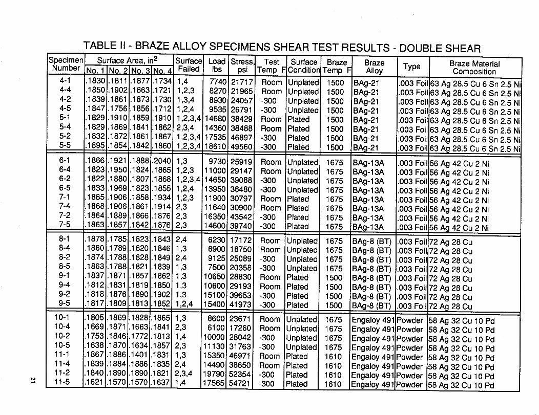
TABLE II - BRAZE ALLOY SPECIMENS SHEAR TEST RESULTS - DOUBLE SHEAR
Specimen Surface Area, in 2 Surface Load Stress. Test SurfaceNumber No. 1 No. 2 No. 3 No. 4 Failed Ibs psi Temp F Conditior
4-1 !.1830.1811 .1877.1734 1,4 7740 21717 Room Unplated
4-4 .1850!.1902.1863.1721 1,2,3 8270 21965 Room Unplated
4-2 .1839.1861 .1873.1730 1,3,4 8930 24057 -300 iUnplated4-5 .1847.1756.1856.171,_ 1,2,4 9535 26791 -300 Unplated5-1 .1829.1910.1859.1910i 1,2,3,4 14680 38429 Room Plated
5-4 .1829.1869.1841 .1862 2,3,4 14360 38488 Room Plated5-2 .1832.1872.1861 .1867 1,2,3,4 17535 46897 -300 Plated
5-5 .1895.1854.1842.1860 1,2,3,4 18610 49560 -300 Plated
6-1 .1866.1921 .1888.2040 1,3 9730 25919 Room Unplated6-4 1823i.1950.1824.1865 1,2,3 11000 29147, Room Unplated6-2 1822_.1880;.1807 1868 1,2,3,4 14650 39088 _ -300 Unplated
6-5 1833.1969!.1823 1855 1,2,4 13950 36480 -300 Unplated7-1 1885.1906 1858.1934 !,2,3 11900 30797 Room Plated
7-4 1868.1906 186t .1914 2,3 11640 30900 Room Plated7-2 .1864 1889 1866.1876 2,3 16350 43542 -300 Plated7-5 .1863 1857 1842.1876 2,3 14600 39740 -300 Plated
8-1 .1878 1785.1823.1843 2,4 6230 17172 Room Unplated
8-4 .1860.1789.1820.1846 1,3 6900 18750 Room Unplated8-2 .1874.1788.1828.1849 2,4 9125 25089 -300 Unplated
8-5 .1863.1788.1821 .1839 1,3 7500 20358 -300 Unplated9-1 .1837.1871 .1857.1862 1,3 10650 28830 Room Plated9-4 .1812.1831 .1819.1850 1,3 10600 29193 Room iPlated
9-2 .1818.1876.1890.1902 1,3 15100 39653 -300 Plated9-5 .1817.1809.1813.1852 1,2,4 15400 41973 -300 Plated
10-1 .1805.18691.1828.1865 1,3 8600 23671 Room Unplated10-4 .1669.1871.1663.1841 2,3 6100 17260 Room Unplated10-2 i=.1753 i.1846 .1772 .1813 1,4 _10000 28042 -300 Unplated
10-5 .1638.1870.1634.1857 2,3 11130 31763 -300 Unplated11-1 .1867.1886.1401 .1831 1,3 15350 46971 Room Plated11-4 .1839.1884.1886.1835 2,4 14490 38650 Room Plated
11-2 .1840.1890.1890.1821 2,3,4 19790 52354 -300 Plated
11-5 .1621 .1570.1570 1637 1,4 17565 54721 -300 Plated
BrazeTemp F
150O1500
1500
15001500
1500
15001500
1675
16751675
16751675
16751675
1675
16751675
16751675
150O1500
1500
1500
1675
1675
16751675
16101610
16101610
BrazeAlloy
BAg-21BAg-21
BAg-21
!BAg-21BAg-21
BAg-21
BAg-21
BAg-21
BAg- 13A
BAg-13ABAg - 13A
BAg-13ABAg-13A
BAg-13ABAg- 13A
BA_I- 13A
BAg-8 (BT)BAg-8 (BT)
BAg-8 (BT)BAg-8 (BT)
BAg-8 (BT)
BAg-8 (BT)iBAg-8 (BT)
BAg-8 (BT)
Engaloy 491
Engaloy 491
Engaloy 491Engaloy 491
Engaloy 491
Engaloy 491Engaloy 491Engaloy 491
Type
.003 Foil!.003 Foil
.003 Foil
.003 Foil
.003 Foil
.003Foil
.003 Foil
.003 Foil
.003 Foil
.003 Foil.003 Foil
.003 Foil.003Foil
.003 Foil
.003 Foil
.003 Foil;
.003 Foili.003 Foil
.003 Foil
.003 Foil
.003 Foil
.003 Foil
.003 Foil
.003 Foil
Powder
Powder
PowderPowder
PowderPowder
PowderPowder
Braze MaterialComposition
63 Ag 28.5 Cu 6 Sn 2.5 Ni
63 Ag 28.5 Cu 6 Sn 2.5 Ni63 Ag 28.5 Cu 6 Sn 2.5 Ni
63 Ag 28.5 Cu 6 Sn 2.5 Ni63 Ag 28.5 Cu 6 Sn 2.5 Ni
63 Ag 28.5 Cu 6 Sn 2.5 Ni
63 Ag 28.5 Cu 6 Sn 2.5 Ni
63 Ag 28.5 Cu 6 Sn 2.5 Ni
56 Ag 42 Cu 2 Ni
56 Ag 42 Cu 2 Ni56 Ag 42 Cu 2 Ni
56 Ag 42 Cu 2 Ni56 Ag 42 Cu 2 Ni
56 Ag 42 Cu 2 Ni
56 Ag 42 Cu 2 Ni
56 Ag 42 Cu 2 Ni
72 Ag 28 Cu72 Ag 28 Cu
72 Ag 28 Cu72 Ag 28 Cu
72 Ag 28 Cu
72 Ag 28 Cu72 Ag 28 Cu72 Ag 28 Cu
58 Ag 32 Cu 10 Pd158 Ag 32 Cu 10 Pd
'58 Ag 32 Cu 10 Pd58 Ag 32 Cu 10 Pd
58 Ag 32 Cu 10 Pd
58 Ag 32 Cu 10 Pd58 Ag 32 Cu 10 Pd58 Ag 32 Cu 10 Pd
t_
TABLE II- BRAZE ALLOY SPECIMENS SHEAR
SpecimenNumber
Surface Area, in 2
No. 1 No. 2 No. 3 No. 4
.1230.1216.1227.1226•1688.1661 . 1701 .1697
* .1234 * i.1225.1237.1191 .1242 !.1207
•1563 *. 1582 *
.1410.1 539.1413.1 525
.1191 .1084.1193.1099
•1098.1233.1104.1225
SurfaceFailed
1,2,31,2,3
1,2,3
2,31,2,3
1,2,3
2,3,41,2,3
13-113-4
13-2
13-512-1
12-412-2
12-5
Load Stress TestIbs psi Temp F
16200 65934 Room19630 57923 Room
19880 ** -300
20000 82203 -30019350 ** Room
16450 55725 Room18265 80215 -300
16740 71630 -300
EST RESULTS - DOUBLE SHEAR (Continued)Surface
Condition
Unplated
UnplatedUnplated
UnplatediPlatedPlated
iPlated!Plated
BrazeTemp F
18001800
18001800
1800
18001800
1800
BrazeAlloy
BAu-4BAu-4
BAu-4
BAu-4BAu-4
BAu-4BAu-4
BAu-4
Type
.003 Foil
.003 Foil
.003 Foil
.003 Foil
.003 Foil
.003 Foil
.003 Foil
.003 Foil
Braze MaterialComposition
82 Au 18 Ni
82 Au 18 Ni82 Au 18 Ni
82 Au 18 Ni82 Au 18 N i
82 Au 18 Ni
82 Au 18 Ni82 Au 18 Ni
* Accurate measurement of area not obtained on these surfaces
** Stress calculation not provided for these specimens
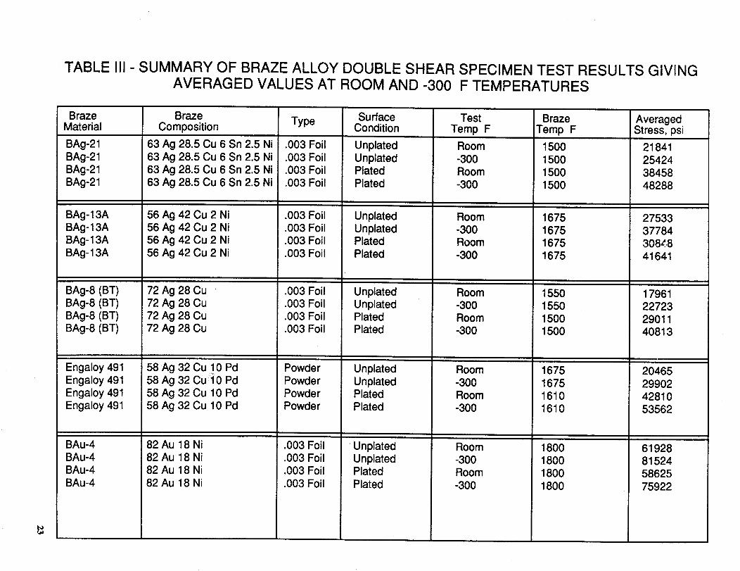
TABLE III- SUMMARY OF BRAZE ALLOY DOUBLE SHEAR SPECIMEN TEST RESULTS GIVINGAVERAGED VALUES AT ROOM AND -300 F TEMPERATURES
BrazeMaterial
BAg-21
BAg-21BAg-21
BAg-21
BAg-13A
BAg-13ABAg-13A
BAg-13A
BAg-8 (BT)
BAg-8 (BT)BAg-8 (BT)
BAg-8 (BT)
Engaloy 491Engaloy 491
Engaloy 491Engaloy 491
BAu-4
BAu-4BAu-4
BAu-4
BrazeComposition
63 Ag 28.5 Cu 6 Sn 2.5 Ni
63 Ag 28.5 Cu 6 Sn 2.5 Ni63 Ag 28.5 Cu 6 Sn 2.5 Ni
63 Ag 28.5 Cu 6 Sn 2.5 Ni
56 Ag 42 Cu 2 Ni
56 Ag 42 Cu 2 Ni56 Ag 42 Cu 2 Ni
56 Ag 42 Cu 2 Ni
72 Ag 28 Cu
72 Ag 28 Cu72 Ag 28 Cu
72 Ag 28 Cu
58 Ag 32 Cu 10 Pd58 Ag 32 Cui0 Pd
58 Ag 32 Cu 10 Pd58 Ag 32 Cu 10 Pd
82 Au 18 Ni82 Au 18 Ni
82 Au 18 Ni
82 Au 18 Ni
Type
.003 Foil
.003 Foil
.003 Foil
.003 Foil
.003 Foil
.003 Foil
.003 Foil
.003 Foil
.003 Foil
.003 Foil.003 Foil
.003 Foil
PowderPowder
PowderPowder
.003 Foil
.003 Foil
.003 Foil
.003 Foil
SurfaceCondition
Unplated
UnplatedPlatedPlated
UnplatedUnplatedPlated
Plated
UnplatedUnplatedPlatedPlated
Unplated
UnplatedPlatedPlated
UnplatedUnplatedPlated
Plated
TestTemp F
Room-300
Room-300
Room
-300Room
-300
Room-300
Room
-300
Room
-300
Room-300
Room
-300Room
-300
BrazeTemp F
1500
1500
15001500
1675
167516751675
15501550
15001500
1675
16751610
1610
18001800
1800
1800
AveragedStress, psi
2184125424
38458
48288
275333778430848
41641
17961
2272329011
40813
20465
2990242810
53562
6192881524
5862575922
41_
BrazeMaterial
BAg-21BAg-21BAg-21BAg-21
BAg- 13ABAg-13ABAg- 13ABAg-13A
BAg-8 (BT)BAg-8 (BT)BAg-8 (BT)BAg-8 (BT)
Engaloy491Engaloy491Engaloy491Engaloy491
BAu-4BAu-4BAu-4BAu-4
TABLE IV - SUMMARY OF BRAZE ALLOY SINGLE SHEAR SPECIMEN TEST RESULTS GIVINGAVERAGED VALUES AT ROOM AND -300°F TEMPERATURES
BrazeComposiUon
63 Ag 28.5 Cu 6 Sn 2.5 Ni63 Ag 28.5 Cu 6 Sn 2.5 Ni63 Ag 28.5 Cu 6 Sn 2.5 Ni63 Ag 28.5 Cu 6 Sn 2.5 Ni
56 Ag 42 Cu 2 Ni56 Ag 42 Cu 2 Ni56 Ag 42 Cu 2 Ni56 Ag 42 Cu 2 Ni
72 Ag 28 Cu72 Ag 28 Cu72 Ag 28 Cu72 Ag 28 Cu
58 Ag 32 Cu 10 Pd58 Ag 32 Cu 10 Pd-58 Ag 32 Cu 10 Pd58 Ag 32 Cu 10 Pd
82 Au 18 Ni82 Au 18 Ni82 Au 18 Ni82 Au 18 Ni
Type
.003 Foil
.003 Foil
.003 Foil
.003 Foil
.003 Foil
.003 Foil
.003 Foil
.003 Foil
.003 Foil
.003 Foil
.003 Foil
.003 Foil
PowderPowderPowder
i Powder
.003 Foil
.003 Foil
.003 Foil
.003 Foil
SurfaceCondition
UnplatedUnplatedPlatedPlated
UnplatedUnplatedPlatedPlated
UnplatedUnplatedPlatedPlated
UnplatedUnplatedPlatedPlated
UnplatedUnplatedPlatedPlated
TestTemp °F
Room-300Room-300
Room-300Room-300
Room-300Room-300
Room-300Room-300
Room-300Room-300
BrazeTemp°F
1500150015001500
1675167516751675
1550155015001500
1675167516101610
1800180018001800
AveragedStress, psi
105759658
1633417397
11618146732119227362
11040104281887523332
18616251121928924177
40351454502938235313
BrazeMaterial
BAg-21BAg-21BAg-21BAg-21
BAg-13ABAg-13ABAg-13ABAg-13A
BAg-8 (BT)BAg-8 (BT)BAg-8 (BT)BAg-8 (BT)
Engaloy491Engaloy491Engaloy491Engaloy491
BAu-4BAu-4BAu-4BAu-4
TABLE IV - SUMMARY OF BRAZEALLOY SINGLE SHEAR SPECIMENTEST RESULTSGIVINGAVERAGED VALUES AT ROOM AND -300°F TEMPERATURES
Braze Surface Test BrazeComposition Type Condition Temp°F Temp °F
Room-300Room-300
63 Ag 28.5 Cu 6 Sn 2.5 Ni .003Foil63 Ag 28.5 Cu 6 Sn 2.5 Ni .003Foil63 Ag 28.5 Cu 6 Sn 2.5 Ni .003Foil63 Ag 28.5 Cu 6 Sn 2.5 Ni .003Foil
56 Ag 42 Cu 2 Ni56 Ag 42 Cu 2 Ni56 Ag 42 Cu 2 Ni56 Ag 42 Cu 2 Ni
72 Ag 28 Cu72 Ag 28 Cu72 Ag 28 Cu72 Ag 28 Cu
58 Ag 32 Cu 10 Pd58 Ag 32 Cu 10 Pd58 Ag 32 Cu 10 Pd58 Ag 32 Cu 10 Pd
82 Au 18 Ni82 Au 18 Ni82 Au 18 Ni82 Au 18 Ni
.003Foil
.003Foil
.003Foil
.003Foil
.003
.003
.003
.003
FoilFoilFoilFoil
PowderPowderPowderPowder
.003Foil
.003Foil
.003Foil
.003Foil
UnplatedUnplatedPlatedPlated
UnplatedUnplatedPlatedPlated
UnplatedUnplatedPlatedPlated
UnplatedUnplatedPlatedPlated
UnplatedUnplatedPlatedPlated
Room-300Room-300
Room-300Room-300
Room-300Room-300
Room-300Room-300
AveragedStress,psi
1500150015001500
1675167516751675
155015501500i500
1675167516101610
1800180018001800
105759658
1633417397
11618146732119227362
11040104281887523332
18616251121928924177
40351454502938235313
Center Punch10 PlacesSee Detail @
__J_
.25"
Center_Punch _Ik _.003"
_fDetail @Not to scale
PLATE
2 Required per assembly.12"
•25" Typ. r°_
.62"SPLICE PLATE
2 Required - Double shear1 Required - Single shear
26
Figure 1 - Plate Geometry for Shear Specimen
Plate_
Plate
.25" Lap ShearSurface
6.5" 9.1"
Splice Plate
ASSEMBLY
Figure 2 - Structural Assembly for Shear Specimen
2,"/
SpecimenNumber
Surface 2
SingleShear
Specimen Number
_-- Part Number-- Saw Cut! Z/--
10-1 10-2 10-3 10-4
._,-- 1.3"--_Typ..5 I!
10-5
SpecimenNumber
Surface 1 --_ iSurface 3
Surface 2 -/ _- Surface 4
m
DoubleShear
BRAZED ASSEMBLYLayout
28
Figure 3 - Illustration of Brazed Assembly Used forShear Specimens

1.00"
6.0"
SingleShear
.75"
®-
®t
DoubleShear
.625'
-®
I
.-+ _)__
DoubleShear
Room Temp.BAU-4 Braze
Material
.50"
m . .-_* .-¢.- m
_-Rm
I==.,=.,=-
t
DoubleShear
Cryo Temp.BAU-4 Braze
Material
SHEAR SPECIMENS
Figure 4 - Various Shear Specimens Used for Braze Alloy Tests
29
Weight
Weight
Weight Weight
,Weight Weight
FRONT VIEW
Shim
Plate
Weight
Weight
SIDE VIEW
Splice Plate
Plate
Shim
Figure 5 - Illustration of Placement of Braze Specimensin Furnace
31)
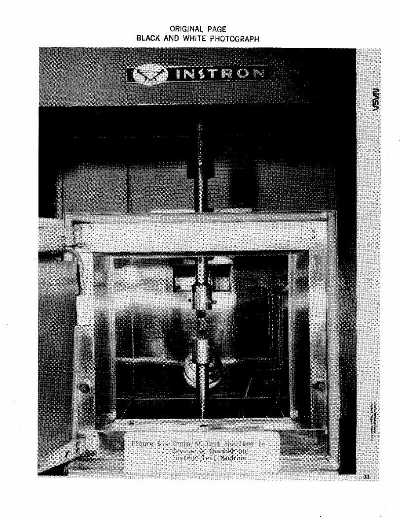
ORIG!NAL PAGEBLACK AND WHITE PHOTOGRAPH
•-Io008 L
I;'-I'IVB
.-IoOOE:" J.l:l
///
III
III
/1¢
iii
,//fil
iiii/i
iii
//
/_ ///
lii
_,./j
//Jli/
fll
iii
///
//I
//I
-Io 0 L9 L O=lJ.V'ld
do SL9 L O':I.LV'ldNN
L6_ AO"IVDN:I
do 00£- .LI::I
do OSS L
(J.U)8 OVado OOt:- ill
/// _,///
//J //_
I/_ //j
//J _//
/// /i_
I/I //j
//i i///
I/2
/// ///
//2 //_
///i
¢//
40 S;_9 L
VgL BV'B
do 00{:- JJ:l
///
,/_ //I
,/_ ///
Ff/ _
.%..
a_lVqd q3MOIN SS_qOS_O3q__
a3ZVqdNnl'----I
"dlN3.L 51ZVI:IB
"IVIEI3.LVIN 5]ZVI::IB
"d_'::l.L ISBI
-0_
Or)-r
- 017 m_>
(n-4
mz
-09 ¢)-!-1-
t,D
-09
OOL
f,I
ORIGINAL PAGE
BLACK AND WHITE PHOTOGRAPH
ORIGINALPAGEBLACK AND WHITE PHOTOGRAPH
ORIGINALPf_GEBLACKAND WHITE PHOTOGRAPH
ORIGINALPAGEBLACKAND WHITE PHOTOGRAP_
Et_
m
t_Im
l //
/
//
/167450
• Load
Figure 12 - Example of Displacement Versus Load for Double BrazeShear Specimen 12-4 @ R.T.
3"/
ORIGINALPf\GEBLACKAND WHITE PHOTOGRAPH
BLACKAND WHI]"E PHOIOG£At.:-H
ORIGINALPAGEBLACK AND WHITE PHOTOGRAPH
OR_G.INALPAGEBLACKAND WHITE PHOTOGRAPH
ORIGINALPAGEBLACKAND WHITE PHOTOGRAPH
Na llOnal A_onaLill(-S and.(;rl,_c e A(]n_lniSlr alF.j_l
1. Report No.
NASA TM-104075
4. Title and Subtitle
Report Documentation Page
2. Government Accession No. 3. Recipient's Catalog No.
5. Report Date
Braze Alloy Process and Strength Characterization Studie_for 18 Nickel Grade 200 Maraging Steel With Applicationto Wind Tunnel Models
7. Author(s)
James F. Bradshaw
Paul G. Sandefur, Jr.
Clarence P. Young, Jr.
9. Performing Organization Name and Address
NASA Langley Research Center
Hampton, VA 23665-5225
12. Spon_ring Agency Name and Address
National Aeronautics and Space Administration
Washington, DC 20546-0001
May 1991
6. Performing Organization Code
8. Performing Organization Report No.
10. Work Unit No.
505-59-85-01
11. Contract or Grant No.
13. Type of Report and Period Covered
Technical Memorandum1990 - 1991
14. Sponsoring ,_gency Code
15. Supp_mentaw Notes
James Bradshaw: Langley Research Center, Hampton, Virginia.
Paul Sandefur: Lockheed Engineering & Sciences Company, Hampton, Virginia.
Clarence P. Young, Jr.: North Carolina State University, Raleigh, North Carolina.
16. Abstract
A comprehensive study of braze alloy selection process and strength characterizationwith application to wind tunnel models is presented. The applications for this studyinclude the installation of stainless steel pressure tubing in model airfoil sectionsmade of 18 Ni 200 grade maraging steel and the joining of wing structuralcomponents by brazing. Acceptable braze alloys for these applications are identified
along with process, thermal braze cycle data, and thermal management procedures.Shear specimens are used to evaluate comparative shear strength properties for thevarious alloys at both room and cryogenic (-300°F) temperatures and include the
effects of electroless nickel plating. Nickel plating was found to significantlyenhance both the wetability and strength properties for the various braze alloysstudied.
The data provided in this paper are provided for use in selecting braze alloys for usewith 18 Ni grade 200 steel in the design of wind tunnel models to be tested in anambient or cryogenic environment.
17. Key Words(SuggestedbyAuthor(s))
Wind tunnel models
Braze process
Braze alloys
Braze strength properties
19. Security Classif. (of this report)
Unclassified
NASA FORM 1626 OCT 86
18. Distribution Statement
Unclassified - Unlimited
Subject Category 26
20. Security Classif. (of this page)
Unclassified
21. No. of pages
47
22. Price
A03


IL Ell