Embed Size (px)
Citation preview


Congratulations and thank you for your purchase of a RED™ CHARGER. Before unpacking and assembling, please review the OPERATION GUIDE. If there is any physical damage to your components, contact us immediately at [email protected].
The RED™ CHARGER lithium-ion battery charger has been designed to manage relatively high currents in order to minimize charging time. The chargers will become warm during operation and it is therefore very important to keep their ventilation openings unobstructed. Moreover, please follow the safety instructions below:
• Protect the equipment from humid environments. Avoid any contact with water or other fluids. Do not use if any liquid has been accidentally spilled inside the equipment. Contact qualified service personnel for inspection or repair.
• Clean only by using a dry cloth.• Unplug when not in use and avoid power surges.• Read the supplied instructions thoroughly and keep handy.• Avoid use near heat sources such as fire places, radiators, stoves or other heat
generating equipment.• NEVER use without proper grounding.• Protect the AC mains power plug, connector and cord.• If the equipment develops a fault, have it repaired by qualified service person-
nel only.• NEVER block the ventilation openings or obstruct cooling fan airflow.• Use only as instructed by the manufacturer.• Do not remove cover or dismantle the apparatus. No user-serviceable parts in-
side.
WARNINGTHIS EQUIPMENT MUST BE EARTHED. TO PREVENT FIRE OR SHOCK HAZ-ARD DO NOT EXPOSE THE UNIT TO RAIN OR MOISTURE. TO AVOID ELECTRIC SHOCK, DO NOT OPEN THE APPARATUS AND ALWAYS REFER ANY SERVICING TO QUALIFIED PERSONNEL.
THE USER IS BEING ALERTED OF THE IMPORTANCE OF GOING THROUGH THE LITERATURE ACCOMPANYING THIS PRODUCT AND FAMILIARIZING HIMSELF WITH THE IMPORTANT SAFETY AND OPERATING INSTRUCTIONS INCLUDED.
RED CHARGER IS INTENDED FOR OPERATION WITH LINE VOLTAGES BETWEEN 100 AND 240V AC AND LINE FREQUENCIES BETWEEN 43Hz AND 60 Hz.
ADDITIONALSAFETYNOTESChargers and/or batteries may become hot during charging. This is normal. Please con-sult RED™ if you notice that either a charger or a battery become excessively hot during the charging operation
Be careful not to block the equipment’s ventilation outlets. Never insert any metallic or any other objects inside the equipment through the ventilation openings or otherwise.
THANKS
SAFETY INSTRUCTIONSPLEASE READ FIRST
The RED™ CHARGER intelligent Lithium ion battery charger has been specifi-cally designed for fast and reliable charging of RED BRICK® V-lock batteries. The charger is capable of delivering 4 Amperes in constant current mode making them particularly suitable to users who require a fast turnaround from their batteries. Ex-ternal dimensions have been kept as compact as possible for maximum portability.
PROPERTIES• Robust construction for studio and field use• Sophisticated electronics for detecting the charging state• Three-color LED indicator for individual charge-station monitoring• Pre-charge function for protecting heavily discharged cells against high currents
until their voltages rise to a safe level. • Maximum compactness and space utilization
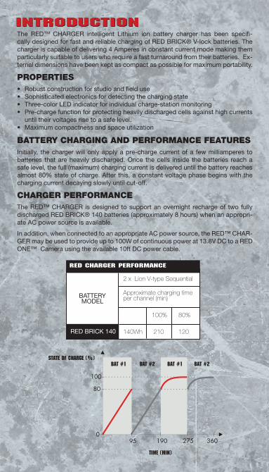
BATTERYCHARGINGANDPERFORMANCEFEATURESInitially, the charger will only apply a pre-charge current of a few milliamperes to batteries that are heavily discharged. Once the cells inside the batteries reach a safe level, the full (maximum) charging current is delivered until the battery reaches almost 80% state of charge. After this, a constant voltage phase begins with the charging current decaying slowly until cut-off.
CHARGERPERFORMANCEThe RED™ CHARGER is designed to support an overnight recharge of two fully discharged RED BRICK® 140 batteries (approximately 8 hours) when an appropri-ate AC power source is available.
In addition, when connected to an appropriate AC power source, the RED™ CHAR-GER may be used to provide up to 100W of continuous power at 13.8V DC to a RED ONE™ Camera using the available 10ft DC power cable.
State of charge (%)
Time (min)
Bat #1 Bat #2 Bat #2Bat #1
950
80
100
190 275 360
2 x Lion V-type Sequential
Approximate charging time per channel (min)
100% 80%
140Wh 210 120
RED CHARGER Performance
BATTERY MODEL
RED BRICK 140
INTRODUCTION

1 CARRYING HANDLE 7 BATTERY 1 LED
2 DC INPUT 22V / 5A MAX 8 BATTERY 2 LED
3 BATTERY RELEASE 9 AUX LED
4 VENTILATION 10 LEMO AUX OUT 13.8V / 100W
5 AC MAINS INPUT 11 MAIN SWITCH
6 ROTATING SUPPORT FOOT 1 12 BATTERY CONTACT AREA
1 - The rotating support foot is pulled out and rotated 90˚ in a left or right hand direction for vertical free standing operation. The unit has been designed to remain in balance with only one battery or with both batteries connected.
7
8
9
10
116
5
4
3
2
1
1212
RED CHARGER OVERVIEW
REDCHARGERCOMPONENTSIncluded with the RED™ CHARGER are:
• RED™ CHARGER* sequential dual position charger with Aux output• Operation Guide• 10 ft. AC power cable• RED BRICK® batteries are sold separately. To order go to www.RED.com/store
Included with the RED™ POWER PACK are:
• RED™ CHARGER sequential dual position charger with Aux output• Operation Guide• 2 - RED BRICK® Batteries• 10 ft. AC power cable• Camera DC power cable (to connect camera to charger for power)
* DC power cable (from RED CHARGER to RED ONE) is sold separately.

The RED™ CHARGER features the highest charging current for a Li-Ion charger in the broadcasting sector. This results in currently the shortest possible battery charging time.
RED BRICK® Li-Ion battery series allow fast charging due to several intrinsic fea-tures such as pre-charge protection and cell balancing; avoiding cell damage and life-cycle shortening, as demonstrated by the life-cycle performances.
Additionally, the new RED™ CHARGER supports and enhances these features with IPCS, a 2 step Intelligent Pre-Charge System.
Since fast charging can damage cells if not properly applied, especial-ly with low voltage (discharged) cells, appropriate care must be taken. The 2 step procedure implemented by IPCS, initially boosts very low voltage cells to a state where charge can be applied with a medium-low current without dam-age, then starts to charge with a 300mA current for a while. Finally, when the pack reaches a reasonable voltage state, it speed-up the charge process by going to full throttle.
The operation implemented by IPCS is only applied if the prevailing cells-state need it, and normally takes a few minutes, depending on the state of discharge of the cells.
15300
15200
15100
15000
14900
14800
14700
500 650 800 957 1107 1260 1410 1560 1710 1860
4500
4000
3500
3000
2500
2000
1500
Time (min)
Before CTP activation:charger at normal speed
After CTP activation:charger at reduced speed
VOLTAGE
CURRENT
VOLTAGE
CURRENT
0 3 5 8 10 13 15 18 20 23
13500
13000
12500
12000
11500
11000
Step-1 Step-2
0 10 20 30 40 50 60 70 80 90 100 110 120 130 140 150 160 170 180 190
17000
16500
16000
15500
15000
14500
14000
13500
13000
Charging Current
Red Charger- charging performance of RED Brick battery packs
Battery Voltage during charge
8000
7500
7000
6500
6000
5500
5000
4500
4000
3500
3000
2500
2000
1500
1000
500
0
Volta
ge (m
V)
Curr
ent (
mA
)
IPCS 2 Step Intelligent Pre-charge System
IPCS AND FAST CHARGING

15300
15200
15100
15000
14900
14800
14700
500 650 800 957 1107 1260 1410 1560 1710 1860
4500
4000
3500
3000
2500
2000
1500
Time (min)
Before CTP activation:charger at normal speed
After CTP activation:charger at reduced speed
VOLTAGE
CURRENT
VOLTAGE
CURRENT
0 3 5 8 10 13 15 18 20 23
13500
13000
12500
12000
11500
11000
Step-1 Step-2
0 10 20 30 40 50 60 70 80 90 100 110 120 130 140 150 160 170 180 190
17000
16500
16000
15500
15000
14500
14000
13500
13000
Charging Current
Red Charger- charging performance of RED Brick battery packs
Battery Voltage during charge
8000
7500
7000
6500
6000
5500
5000
4500
4000
3500
3000
2500
2000
1500
1000
500
0
Volta
ge (m
V)
Curr
ent (
mA
)
Due to the high charging currents developed by the RED™ CHARGER, heat control is an issue for a travel charger, especially if the travel charger is used in potentially hot environments.
To improve the reliability of the device without compromising its usage flexibility, RED™ has developed an innovative feature; CTP (Charger Thermal Protection) that allows the electronics to work out the best possible charge profiles without causing damage, even in adverse temperature conditions.
In case of the charger internal temperature reaching a high level, the charging cur-rent is automatically reduced to avoid possible damage caused by internal over-heating. When the charging speed is reduced, the internal temperature starts to descend. As soon as the temperature reaches a safe level, normal charging speed is resumed.
Through indoor usage, CTP features do not normally intervene (unless the air con-vection flow path is obstructed or the internal cooling fan is damaged).
The operation implemented by CTP is outlined in the chart below.
CTP: FLEXABILITY OFOPERATION ANDCHARGER RELIABILITY

This charger can sequentially charge 2 batteries with charging currents up to 4A.
1. Plug AC power cord into charger AC input and power source.2. Turn the charger power switch ON.3. Insert battery into the V-plate adapter.4. Observe the charger LED. Charger LED will illuminate Orange during charging
(battery LED array will also illuminate displaying charge status).5. Remove battery when charger LED flashes Orange/Green (all battery LEDs will be lit).
NOTE: When a cable is plugged into the 6-pin LEMO auxiliary power output, the charging process will be suspended. The AUX LED will light up and battery LEDs on the charger will blink Green. Once the cable is unplugged, the char-ger will continue the previous charging sequence and from the same point of interruption.
NOTE: To ensure a good connection between and charger V-plate adapters, it is recommended to perform a break-in sequence. To break-in: Fully engage/disengage battery approx. 20 times in each V-plate adaptor.
CHARGING2BATTERIESInsert the second battery into the second V-plate adapter.
• The LEDs will always display the correct status of the charge for each battery.
NOTE: The maximum load that can be connected to the LEMO output should not exceed 100W.
Installing Battery Removing Battery
CHARGING RED BRICK®BATTERIES

It is preferable to charge batteries immediately before use. Some loss from self-discharge can result if the batteries are charged several weeks in advance of their use. However, this slight loss can be topped up at any time without any degradation of battery performance. Batteries should be stored in a cool and dry place. Charg-ing should be performed at temperatures above 5˚C and below 45˚C. Slight heating of the battery is expected to occur during the charge cycle, however if for some reason, the pack temperature reaches 60˚C, charge activity is suspended. The pack resumes normal charging once the temperature drops back to below 50˚C.
RE-CHARGINGOVERTEMPERATUREBATTERIESHigh current draw from a RED BRICK® battery pack can heat the internal cells to a temperature at which it is not safe to perform an immediate fast re-charge. There-fore the RED CHARGER incorporates a cell temperature test for this condition. Specific RED CHARGER behavior depends on the firmware version.
BATTERYWILLNOTCHARGE• Remove/reinstall battery into RED™ CHARGER and ensure battery engages fully.• Ensure lock holds battery securely and click is heard when battery is installed.• Check battery terminal connections. If any are damaged, contact RED support. www.RED.com/support
FIRMWAREPRIORTOV1.4When mounted, if the RED BRICK® battery cell temperature is greater than the maximum allowed value, charge operation is suspended and the LED will indicate solid red. Remove the RED BRICK® battery from the RED™ CHARGER and allow it to cool for a few minutes. On re-mounting the battery on the RED™ CHARGER, if the cell temperature has fallen below the maximum allowed value, the RED™ CHARGER will then proceed to charge the RED BRICK® battery.
FIRMWAREV1.4ANDLATERWhen mounted, if the RED BRICK® battery cell temperature is greater than the maximum allowed value, charge operation is suspended and the LED will flash red (500ms on 500ms off). Leave the RED BRICK® battery mounted. The RED™ CHARGER will retest the battery cell temperature at one minute intervals, and when the cell temperature has fallen below the maximum allowed value the RED™ CHARGER will then proceed to charge the RED BRICK® battery.
NOTES CONCERNING CHARGERUSAGE WITH RED BRICK®BATTERY PACKS

## OPERATING MODETIME OUT
LED INDICATION
1BATTERY DETECTIONBat1 on charge / Bat2 waiting
BATTERY WAITING:GREEN: 1s ON / 1s OFF
2BATTERY NOT ALLOWED10Kohm < ID resistor < 60Kohm
BATTERY NOT ALLOWED:GREEN: 500ms / RED: 500ms
3
BATTERY EVALUATION
i) Total pack voltage < 8000mV
ii) I < 10mAIf the charging does not rise within 30s, the battery does not accept charge
iii) Individual cell voltages < 2800mV10mA < I < 30mA
iv) Individual cell voltages > 2800mVTotal pack voltage < 13000mV30mA < I < 300mA
3600s
1200s
VOLTAGE TOO LOW:RED: 500ms ON / 500ms OFF
BATTERY FAILURE:Steady RED
PRECHARGE-1:ORANGE: 500ms ON / 500ms OFF
PRECHARGE-2:ORANGE: 250ms ON / 250ms OFF
4CONSTANT CURRENT MODE13000mV < V < 16800, I = 4A
18000sCC-MODE:Steady ORANGE
5CONSTANT VOLTAGE MODEV =16800mV, 120mA < I < 4000mA 10800s
CV-MODE:ORANGE: 500ms / GREEN: 500mS
6FULL CHARGEV = 16800mVI = 120mA
FULL CHARGE:Steady GREEN
7
OTHER INDICATIONSIn the case of premature charge termination, the charger retries to charge after 30 seconds. If after 30 minutes, there is still no response, the indication is changed into ‘BATTERY FAILURE’In the case of a battery temporarily not accepting any charge (i.e. an overheated battery) the charger will retry every minute. In this case the charger flashes red indicating a temporary failure
PREMATURE CHARGETERMINATION:RED: 250ms ON / 100ms OFF / 250ms ON / 1s OFF (2 blinks + 1 pause)
BATTERY FAILURE:Steady RED
OPERATING MODES

TECHNICAL SPECIFICATIONS
TYOE Constant current and voltage control system with timer interventions
CC-MODE: Output current 4800mA +/- 2%
CC-MODE: Vmax 16800 ± 50mV (0.3%)
CV-MODE: Vmax 16800 ± 50mV (0.3%)
CV-MODE: Cutoff current 120mA ± 10mA
Short circuit protection Available
Overcharge protection Available
Over temperature protection Available
LEDS 3 colour type for BAT1, BAT2 and AUX
Special features IPCS and CTP
Auxiliary power DC 13.8V - 100W (max)
Power supply AC mains 100V ~ 240V, 47 ~ 63 Hz autoselect
Power consumption 220W
Operating temperature range 0°C to 45°C (32°F to 113°F)
Storage temperature range -20°C to 65°C (-4°F to 149°F)
Dimensions 9.8 x 5.7 x 3.2 in. (250 x 145 x 80 mm)
Weight 970g
This charger has been tested for and is fully CE compliant.
TECHNICAL SPECIFICATIONS

As a responsible manufacturer, RED DIGITAL CINEMA™ is confident of the quality and workmanship of this RED™ CHARGER. We guarantee it to be free from defects in material or workmanship for twelve months from date of purchase. In case of claim, please contact RED DIGITAL CINEMA™ at www.RED.com to obtain an RMA number. Instructions will be provided on how to return the defective equipment to RED™. Equipment found to be faulty in manufacture will be repaired or, at our option, replaced free of charge. This guarantee does not cover defects caused by incorrect handling, inexpert repair, unsuit-able storage, accidental or abnormal conditions of operation, transport damage, tamper-ing, and normal wear. The above guarantee does not affect your statutory rights as a consumer.
Complete information about product warranties and product return policies are available at www.RED.com/support.
ALL WARRANTIES IMPLIED BY LAW, INCLUDING MECHANABILITY, SHALL BE OF A DURATION OF ONE YEAR FROM THE DATE OF PURCHASE. NO OTHER EXPRESS WARRANTY OR GUARANTY EXCEPT AS STATED ABOVE, GIVEN BY A PERSON, FIRM OR CORPORATION WITH RESPECT TO THIS LENS SHALL BE BINDING TO RED. SOME STATE DO NO ALLOW LIMITATIONS ON HOW LONG AN IMPLIED WARRANTY LASTS, SO THE ABOVE LIMITATIONS MAY NOT APPLY TO YOU. NEITHER RED NOR ANY OTHER PERSON, FIRM OR CORPORATION IS OR SHALL BE RESPONSIBLE FOR ANY INCIDENTAL OR CONSEQUENTIAL DAMAGES CAUSED BY THIS EQUIPMENT. SOME STATES DO NOT ALLOW THE EXCLUSION OR LIMITATION OF INCIDENTAL OR CONSEQUENTIAL DAMAGES, SO THE ABOVE LIMITATION OR EXCLUSION MAY NOT APPLY TO YOU.
WARRANTY

• RED™ has made every effort to provide clear and accurate information in this OPERATION GUIDE, which are provided solely for the user’s information. While thought to be accurate, the information in this document is provided strictly “as is” and RED™ will not be held responsible for issues arising from typographical errors or user’s interpretation of the language used herein that is different from that intended by RED™. All safety and general information is subject to change as a result of changes in local, federal or other applicable laws.
• RED™ reserves the right to revise this OPERATION GUIDE and make changes from time to time in the content hereof without obligation to notify any person of such revisions or changes. In no event shall RED™, its employees or authorized agents be liable to you for any damages or losses, direct or indirect, arising from the use of any technical or operational information contained in this document.
DISCLAIMER