Embed Size (px)
DESCRIPTION
1.25 ,mnvhctyrdytxf
Citation preview
7/18/2019 PLC Implementation of the Bottle-filling Application _ EEP
http://slidepdf.com/reader/full/plc-implementation-of-the-bottle-filling-application-eep 1/5
Home Technical Articles Article Categories Contact us Subscribe to articles Subscribe to downloads
El. Enginering Guides
EE General guides
Power Substations
Schneider Electric CTsSiemens Basics of EE
ABB Drives Guides
Industry Automation
Relay control/protection
Alternative Energy
Electrical Software MS Excel Spreadsheets Electrical Design Docs Engineering Resources
Video Lectures – Electrical Engineering PLC Programming Training
Electric Testing and Maintenance (VIDEO)
Network Theorems and Laws
-
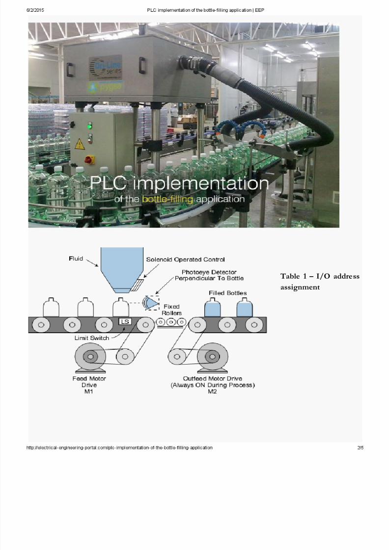
PLC implementation of the bottle-filling
applicationPLC implementation of the bottle-filling application (photo credit: aircontrolindustries.com)
Detection of position
In this example (see Figure 1), we will implement a control program that detects the position of a
bottle via a limit switch, waits 0.5 seconds, and then fills the bottle until a photosensor detects a
filled condition.
After the bottle is filled, the control program will wait 0.7 seconds before moving to the next bottle.
The prog ram will include start and stop circuits for the outfeed motor and the start of the process.
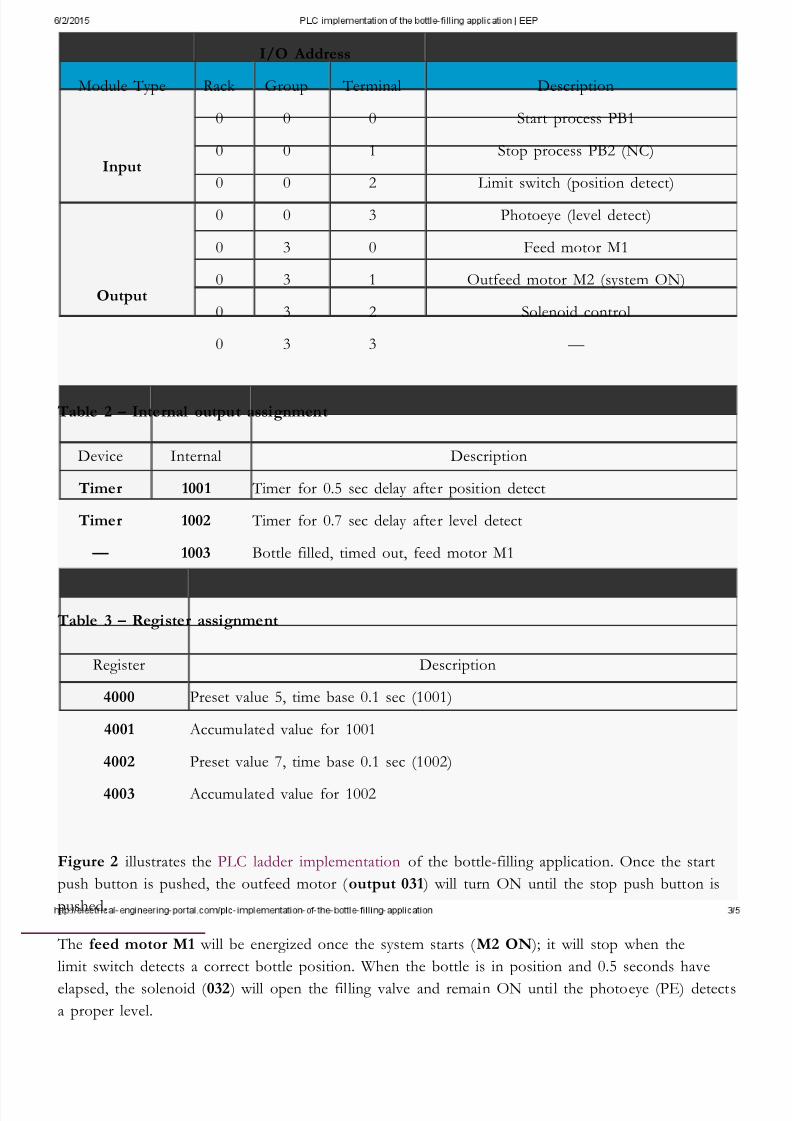
Table 1 shows the I/O address assignment, while Tables 2 and 3 present the internal and register
assignments, respectively.
These assignments include the start and stop process signals.
Figure 1 – Bottle-filling system
7/18/2019 PLC Implementation of the Bottle-filling Application _ EEP
http://slidepdf.com/reader/full/plc-implementation-of-the-bottle-filling-application-eep 2/5
Table 1 – I/O addressassignment
7/18/2019 PLC Implementation of the Bottle-filling Application _ EEP
http://slidepdf.com/reader/full/plc-implementation-of-the-bottle-filling-application-eep 3/5
I/O Address
Module Type Rack Group Terminal Description
Input
0 0 0 Start process PB1
0 0 1 Stop process PB2 (NC)
0 0 2 Limit switch (position detect)
0 0 3 Photoeye (level detect)
Output
0 3 0 Feed motor M1
0 3 1 Outfeed motor M2 (system ON)
0 3 2 Solenoid control
0 3 3 —
Table 2 – Internal output assignment
Device Internal Description
Timer 1001 Timer for 0.5 sec delay after position detect
Timer 1002 Timer for 0.7 sec delay after level detect
— 1003 Bottle filled, timed out, feed motor M1
Table 3 – Register assignment
Register Description
4000 Preset value 5, time base 0.1 sec (1001)
4001 Accumulated value for 1001
4002 Preset value 7, time base 0.1 sec (1002)
4003 Accumulated value for 1002
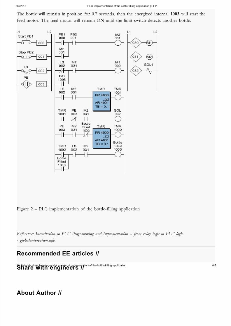
Figure 2 illustrates the PLC ladder implementation of the bottle-filling application. Once the start
push button is pushed, the outfeed motor ( output 031 ) will turn ON until the stop push button is
pushed.
The feed motor M1 will be energized once the system starts ( M2 ON ); it will stop when the
limit switch detects a correct bottle position. When the bottle is in position and 0.5 seconds have
elapsed, the solenoid ( 032 ) will open the filling valve and remain ON until the photoeye (PE) detects
a proper level.
7/18/2019 PLC Implementation of the Bottle-filling Application _ EEP
http://slidepdf.com/reader/full/plc-implementation-of-the-bottle-filling-application-eep 4/5
The bottle will remain in position for 0.7 seconds, then the energized internal 1003 will start the
feed motor. The feed motor will remain ON until the limit switch detects another bottle.
Figure 2 – PLC implementation of the bottle-filling application
Reference: Introduction to PLC Programming and Implementation – from relay logic to PLC logic
- globalautomation.info
Recommended EE articles //
Share with engineers //
About Author //
7/18/2019 PLC Implementation of the Bottle-filling Application _ EEP
http://slidepdf.com/reader/full/plc-implementation-of-the-bottle-filling-application-eep 5/5
Edvard Csanyi
Edvard - Electrical engineer, programmer and founder of EEP. Highly
specialized for design of LV high power busbar trunking (<6300A) in power
substations, buildings and industry fascilities. Designing of LV/MV
switchgears. Professional in AutoCAD programming and web-design.
Present on Google+
© 2015 EEP - Electrical Engineering Portal. All Rights Reserved | Privacy
Policy | 30 queries in 0.208 seconds.
Powered by CsanyiGroup
SHARE
TOP
Get