Embed Size (px)
Citation preview

Plate Girder P.1
PLATE GIRDER Plate girders are custom fabricated beam members used to carry large loads over long spans. They are used in buildings and industrial structures for long-span floor girders, for heavy crane girders and in bridges. Typical plate girders:

Plate Girder P.2
Web Stiffeners are generally required either to prevent buckling due to compression from bending and shear or to promote tension filed action to increase shear strength. Stiffeners are also required at load points and supports to prevent local failure (bearing, local flexural buckling of web). Types of beam cross-section

Plate Girder P.3
Typical usage of different forms of beam

Plate Girder P.4
Initial Section Dimensions
Depth (D) – may be limited by headroom requirement or typically taken as 1/10 to 1/20 span length.
Breadth (B) – usually about 0.3 to 0.5 D with 0.4D typical. The deeper the girder, the smaller the flanges, but thicker web and additional stiffeners may be necessary. However, a shallow girder can be very much heavier and more expensive than a deeper girder.
• Component Dimensions
Generally, a plate girder may be assumed to consist of semi-compact flange plates (which alone resist the applied moment) and a slender web (which carries the applied shear).
Flanges: at least semi-compact with yfp
27513Tb
≤
Webs: often slender with local web buckling in shear - Min web thickness for serviceability (to prevent damage in
handling)
Cl.4.4.2.2 (a) without stiffeners
250dt ≥
(b) with stiffeners
if a > d , 250dt ≥
a < d , da
250dt ≥

Plate Girder P.5
- Min web thickness to avoid flange buckling into web
Cl.4.4.2.3 (a) without stiffeners
≥
345p
250dt yf
(b) with stiffeners
if a > 1.5 d ,
≥
345p
250dt yf
a < 1.5 d , 455p
250dt yf≥
Typical web thickness:
10t ≈ mm as d = 1200mm ; 20t ≈ mm as d = 2500mm
Typical web stiffeners spacing: 6.12.1da
−≈
end panel spacing: 0.16.0da
−≈
• Moment Capacity of Plate Girder
Where the flanges are plastic, compact or semi-compact, but the
web is thin (i.e. ε> 63td ) or slender, the Mc can be calculated
by:
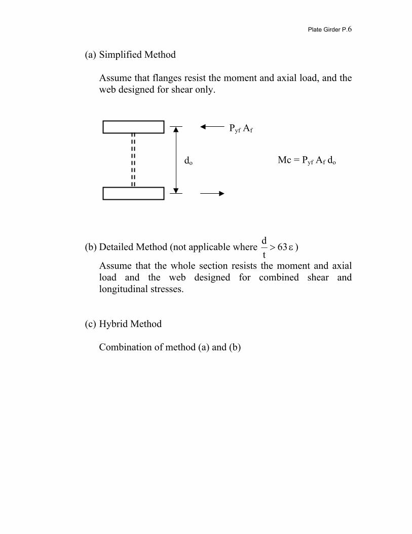
Plate Girder P.6
(a) Simplified Method Assume that flanges resist the moment and axial load, and the web designed for shear only.
(b) Detailed Method (not applicable where ε> 63td )
Assume that the whole section resists the moment and axial load and the web designed for combined shear and longitudinal stresses.
(c) Hybrid Method
Combination of method (a) and (b)
Pyf Af
do Mc = Pyf Af do

Plate Girder P.7
Buckling and Post buckling Behaviour of Web At buckling:
- For pure beam shear action, principal stresses occur at 45° inclinations
- Web buckling occurs when the 45° principal compressive
stress reaches it critical limit Post-buckling tension field action:
dt
- After web buckling, a tensile membrane stress σt develops at an inclination θt to the horizontal
- This tension field action gives the shear panel
considerable post-buckling strength since the increase in tension is limited only by the yield stress
- Truss analogy

Plate Girder P.8
- Total stress state at the inclination of the tension field (θt)
ttcr 2sinqt
σ+θ=σθ
tcr 2sinq90t
θ−=σ+
θ
tcr 2cosqt
θ=τθ - Apply the von Misses-Hencky yield criterion
2 2 2 290 90 3
t t tt tywpθ θθ θ θσ σ σ σ τ
+ ++ − + =
⇒ [ ] tcr21
t22
cr2
cr2
ywt 2sinq5.1 2sinq25.2q3p θ−θ+−=σ
- Maximum shear gained by tension field action using web anchorage
alone occurs approximately when
2t1
t
da1
12sinadtan2
+
=θ⇒
=θ −

Plate Girder P.9
- So the basic tension field strength, yb, is obtained as
[ ] t21
2t
2cr
2ywtb q3py φ−φ+−=σ= , where
2cr
t
da1
q5.1
+
=φ
- Determine the web shear resistance due to tension field action Resultant of tension field action:
( )thttbt sinCsinacosdtyF θ+θ−θ= Shear resistance of web due to Ft:
( )htt2
b
ttt
Cacotdsinty
sinFV
+−θθ=
θ=
Note that Ch represents the distance of the flange which acts an anchorage for developing the tension field action.

Plate Girder P.10
At collapse: - Once the web has yielded, final failure occurs when plastic hinges
have formed in the flanges at points W, X, Y and Z. - Note that the plastic hinge at point W is developed at the position
where the moment is maximum such that the corresponding shear value is zero.
Determination of the distance Ch
Take moment at X,
2sinCsintCyM2 th
thbpfθ
⋅θ=
⇒ ty
Msin
2Cb
pf
th θ
=
Take moment at W, additional flange dependent shear resistance upon collapse,
h
pff C
M4V =
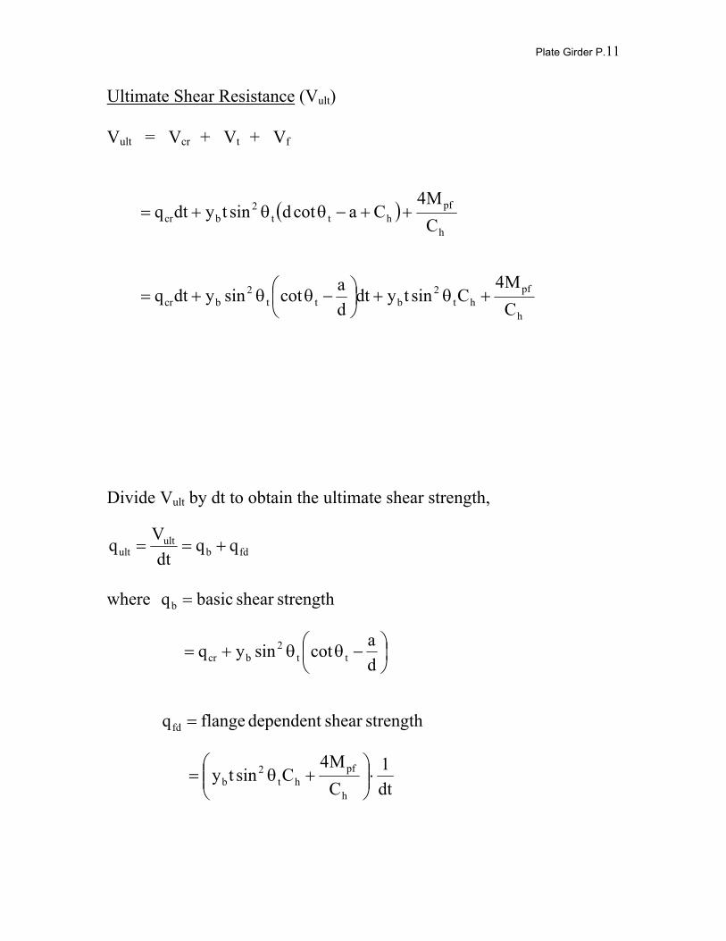
Plate Girder P.11
Ultimate Shear Resistance (Vult) Vult = Vcr + Vt + Vf
( )h
pfhtt
2bcr C
M4Cacotdsintydtq ++−θθ+=
h
pfht
2btt
2bcr C
M4Csintydt
dacotsinydtq +θ+
−θθ+=
Divide Vult by dt to obtain the ultimate shear strength,
fdbult
ult qqdt
Vq +==
where strengthshear basicqb =
−θθ+=
dacotsinyq tt
2bcr
strengthshear dependent flangeqfd =
dt1
CM4
Csinty h
pfht
2b ⋅
+θ=
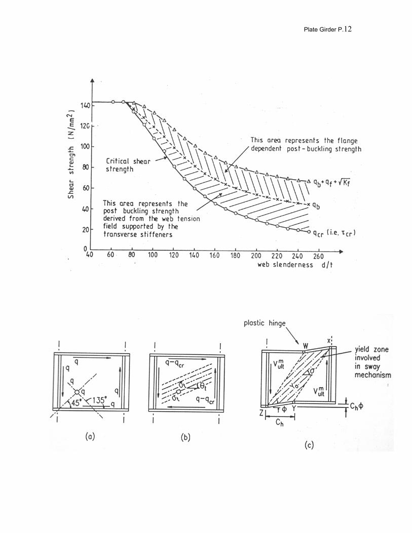
Plate Girder P.12


![Fast Machining Oil & Gas Industry - vargusuk.co.uk Vardex EE[080811]web_1… · Oil & Gas Industry Fast Machining ... Carbide Inserts for API Round and Buttress Thread ... excellent](https://img.pdfslide.us/doc/110x75/5a6fd2067f8b9ab1538b65ab/fast-machining-oil-gas-industry-vargusukcoukwwwvargusukcoukdownloadfilesspotlight.jpg)


![catalogo mediateca in consultazione R>Z [file pdf / 700 KB]](https://img.pdfslide.us/doc/110x75/6232cc27e3a77121545c33f3/catalogo-mediateca-in-consultazione-rgtz-file-pdf-700-kb.jpg)