Embed Size (px)
Citation preview
Planning Guidefor Residential Elevators
ASME A17.1, Part V, Section 5.3
February 2, 2010
ThyssenKrupp AccessResidential Elevator Division Th
ysse
nKru
pp

Page 2
Page 3
Introduction
This Planning Guide is designed to assist architects, contractors, home owners and elevator professionals in planning for a home elevator that meets the requirements of ASME A17.1 Part V Section 5.3.
We strongly recommend you contact the codes authority having jurisdiction in the area(s) where the elevator will be installed. Become familiar with all requirements governing the installation and use of elevators in private residences. It is extremely important for you to know and adhere to all regulations concerning installation and use of elevators.
IMPORTANT NOTICE:This Planning Guide provides nominal dimensions and specifications useful for INITIAL planning of an elevator project. BEFORE beginning actual construction, be sure to receive application drawings customized with specifications and dimensions for your specific project. Call 1-800-829-9760 to find a dealer in your area or visit our website, www.tkaccess.com and click on “Request Information”.
Elevator configurations and dimensions are in accordance with our interpretation of the standards set forth by ASME A17.1 Part V Section 5.3. Please consult ThyssenKrupp Access or an authorized dealer in your area for more specific information pertaining to your project, including any deviation between referenced standards and those of any local codes or laws. Always contact local codes authorities for any variation to standards.
The dimensions and specifications in this Planning Guide are subject to constant change (without notice) due to product enhancements and continually evolving codes and product applications.
This elevator requires 230 VAC, single phase 60 Hz circuit with ground. 20 amp circuit for counterweighted chain drive.
Contents
Equipment for Lev residential elevator .............................................................. 4
Hoistway size requirements (pocketed gates) .................................................5-7
Hoistway size requirements (optional, non-pocketed gates) ........................... 8-10
Hoistway construction notes ......................................................................... 11
Guide rail backing construction details ........................................................... 11
Rail reactions .............................................................................................. 11
Typical counterweighted chain drive area construction details ........................... 12
Optional drive unit area construction details with remote located controller ......... 13 Service Access Hatch .................................................................................. 14
Description of features ............................................................................ 15-17
3-Part specifications ............................................................................... 18-21
Counterweighted chain drive overview ........................................................... 22
Steps of planning for a Lev® Home Elevator:
1. Determine customer’s intention for use.
2. Determine code requirements of site.
3. Determine installation parameters of site.
4. Determine the car type and hoistway size requirements (see pages 5 through 10).
Page 4
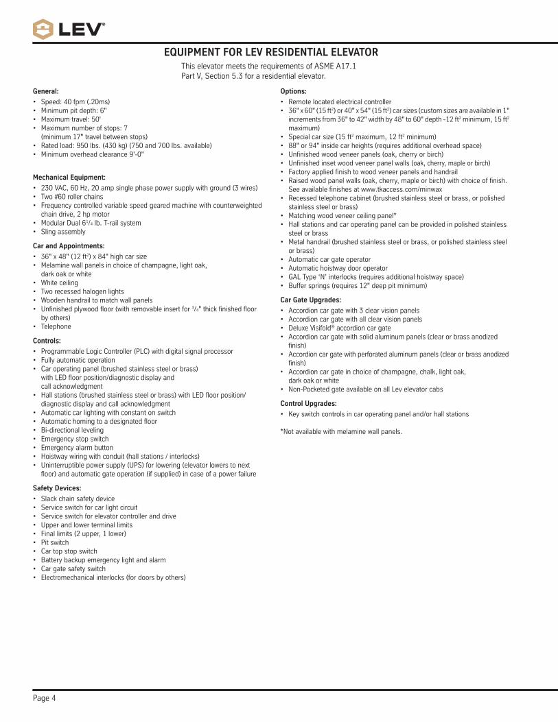
This elevator meets the requirements of ASME A17.1 Part V, Section 5.3 for a residential elevator.
EQUIPMENT FOR LEV RESIDENTIAL ELEVATOR
General:
• Speed:40fpm(.20ms)• Minimumpitdepth:6"• Maximumtravel:50'• Maximumnumberofstops:7 (minimum17"travelbetweenstops)
• Ratedload:950lbs.(430kg)(750and700lbs.available)• Minimumoverheadclearance9'-0"
Mechanical Equipment:
• 230VAC,60Hz,20ampsinglephasepowersupplywithground(3wires)• Two#60rollerchains• Frequencycontrolledvariablespeedgearedmachinewithcounterweighted
chain drive, 2 hp motor• ModularDual61/4 lb. T-rail system• Slingassembly
Car and Appointments:
• 36"x48"(12ft2)x84"highcarsize• Melaminewallpanelsinchoiceofchampagne,lightoak,
dark oak or white• Whiteceiling• Tworecessedhalogenlights• Woodenhandrailtomatchwallpanels• Unfinishedplywoodfloor(withremovableinsertfor3/4"thickfinishedfloor
by others)• Telephone
Controls:
• ProgrammableLogicController(PLC)withdigitalsignalprocessor• Fullyautomaticoperation• Caroperatingpanel(brushedstainlesssteelorbrass) withLEDfloorposition/diagnosticdisplayand call acknowledgment
• Hallstations(brushedstainlesssteelorbrass)withLEDfloorposition/diagnostic display and call acknowledgment
• Automaticcarlightingwithconstantonswitch• Automatichomingtoadesignatedfloor• Bi-directionalleveling• Emergencystopswitch• Emergencyalarmbutton• Hoistwaywiringwithconduit(hallstations/interlocks)• Uninterruptiblepowersupply(UPS)forlowering(elevatorlowerstonextfloor)andautomaticgateoperation(ifsupplied)incaseofapowerfailure
Safety Devices:
• Slackchainsafetydevice• Serviceswitchforcarlightcircuit• Serviceswitchforelevatorcontrolleranddrive• Upperandlowerterminallimits• Finallimits(2upper,1lower)• Pitswitch• Cartopstopswitch• Batterybackupemergencylightandalarm• Cargatesafetyswitch• Electromechanicalinterlocks(fordoorsbyothers)
Options:
• Remotelocatedelectricalcontroller• 36"x60"(15ft2)or40"x54"(15ft2)carsizes(customsizesareavailablein1"incrementsfrom36"to42"widthby48"to60"depth-12ft2 minimum, 15 ft2 maximum)
• Specialcarsize(15ft2 maximum, 12 ft2 minimum)• 88"or94"insidecarheights(requiresadditionaloverheadspace)• Unfinishedwoodveneerpanels(oak,cherryorbirch)• Unfinishedinsetwoodveneerpanelwalls(oak, cherry, maple or birch)• Factoryappliedfinishtowoodveneerpanelsandhandrail• Raisedwoodpanelwalls(oak,cherry,mapleorbirch)withchoiceoffinish.
See available finishes at www.tkaccess.com/minwax• Recessedtelephonecabinet(brushedstainlesssteelorbrass,orpolished
stainless steel or brass)• Matchingwoodveneerceilingpanel*• Hallstationsandcaroperatingpanelcanbeprovidedinpolishedstainless
steel or brass• Metalhandrail(brushedstainlesssteelorbrass,orpolishedstainlesssteel
or brass)• Automaticcargateoperator• Automatichoistwaydooroperator• GALType‘N’interlocks(requiresadditionalhoistwayspace)• Buffersprings(requires12"deeppitminimum)
Car Gate Upgrades:
• Accordioncargatewith3clearvisionpanels• Accordioncargatewithallclearvisionpanels• DeluxeVisifold® accordion car gate• Accordioncargatewithsolidaluminumpanels(clearorbrassanodized
finish)• Accordioncargatewithperforatedaluminumpanels(clearorbrassanodized
finish)• Accordion car gate in choice of champagne, chalk, light oak,
dark oak or white• Non-PocketedgateavailableonallLevelevatorcabs Control Upgrades:
• Keyswitchcontrolsincaroperatingpaneland/orhallstations
*Notavailablewithmelaminewallpanels.
Page 5
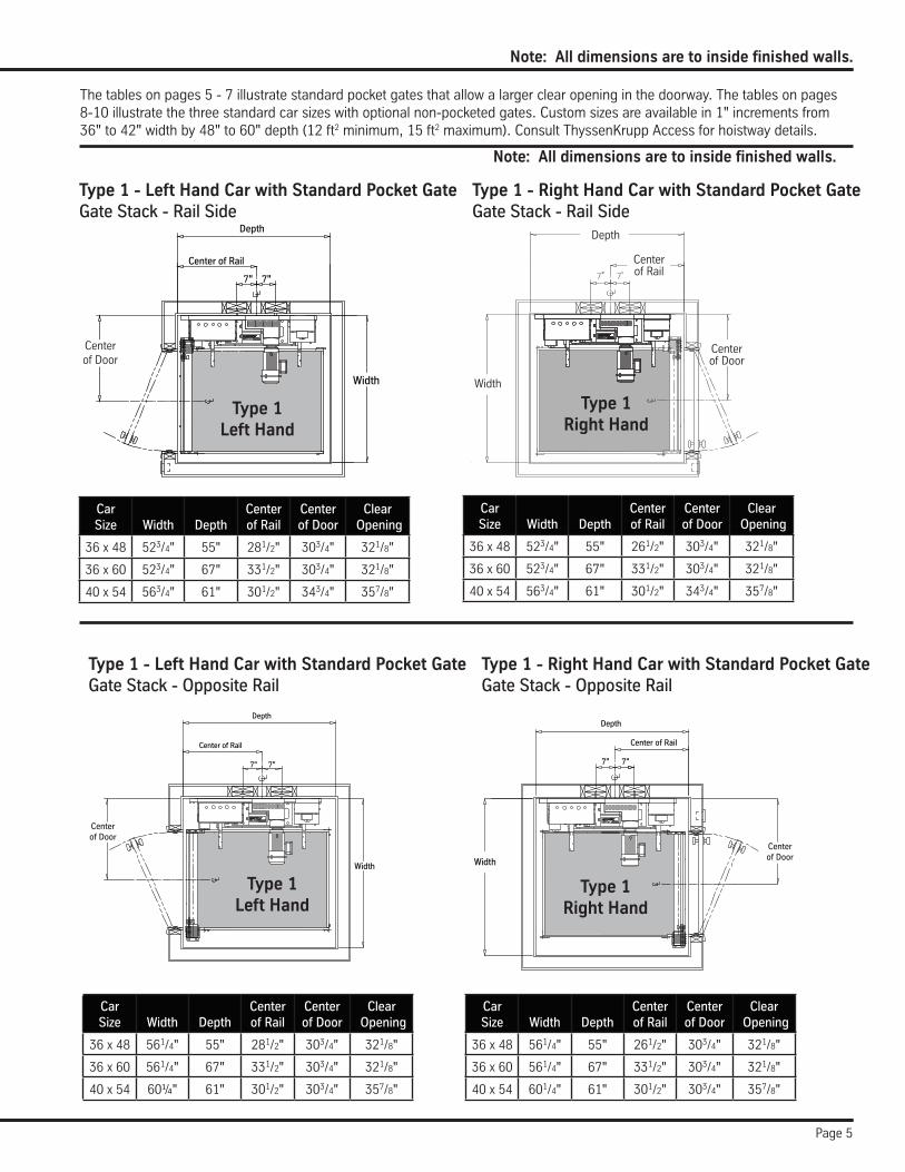
Note: All dimensions are to inside finished walls.
The tables on pages 5 - 7 illustrate standard pocket gates that allow a larger clear opening in the doorway. The tables on pages 8-10illustratethethreestandardcarsizeswithoptionalnon-pocketedgates.Customsizesareavailablein1"incrementsfrom36"to42"widthby48"to60"depth(12ft2 minimum, 15 ft2 maximum). Consult ThyssenKrupp Access for hoistway details.
Type 1 - Left Hand Car with Standard Pocket GateGate Stack - Opposite Rail
Type 1 - Right Hand Car with Standard Pocket GateGate Stack - Opposite Rail
Note: All dimensions are to inside finished walls.
Car Size
Width
Depth
Center of Rail
Center of Door
Clear Opening
36 x 48 561/4" 55" 281/2" 303/4" 321/8"
36 x 60 561/4" 67" 331/2" 303/4" 321/8"
40 x 54 60¼" 61" 301/2" 303/4" 357/8"
Car Size
Width
Depth
Center of Rail
Center of Door
Clear Opening
36 x 48 561/4" 55" 261/2" 303/4" 321/8"
36 x 60 561/4" 67" 331/2" 303/4" 321/8"
40 x 54 601/4" 61" 301/2" 303/4" 357/8"
Depth
Width
HoistwayCenterline
Center of Rail
7" 7"
Type 1Left Hand
Type 1 - Left Hand Car with Standard Pocket GateGate Stack - Rail Side
Type 1 - Right Hand Car with Standard Pocket GateGate Stack - Rail Side
Width
Depth
Centerof Rail
Center of Door
Type 1Right Hand
Car Size
Width
Depth
Center of Rail
Center of Door
Clear Opening
36 x 48 523/4" 55" 281/2" 303/4" 321/8"
36 x 60 523/4" 67" 331/2" 303/4" 321/8"
40 x 54 563/4" 61" 301/2" 343/4" 357/8"
Car Size
Width
Depth
Center of Rail
Center of Door
Clear Opening
36 x 48 523/4" 55" 261/2" 303/4" 321/8"
36 x 60 523/4" 67" 331/2" 303/4" 321/8"
40 x 54 563/4" 61" 301/2" 343/4" 357/8"
Depth
Width
HoistwayCenterline
Center of Rail
7" 7"
Type 1Left Hand
Centerof Door
Centerof Door
Depth
Width
HoistwayCenterline
Center of Rail
7" 7"
Type 1Right Hand
Centerof Door
Page 6
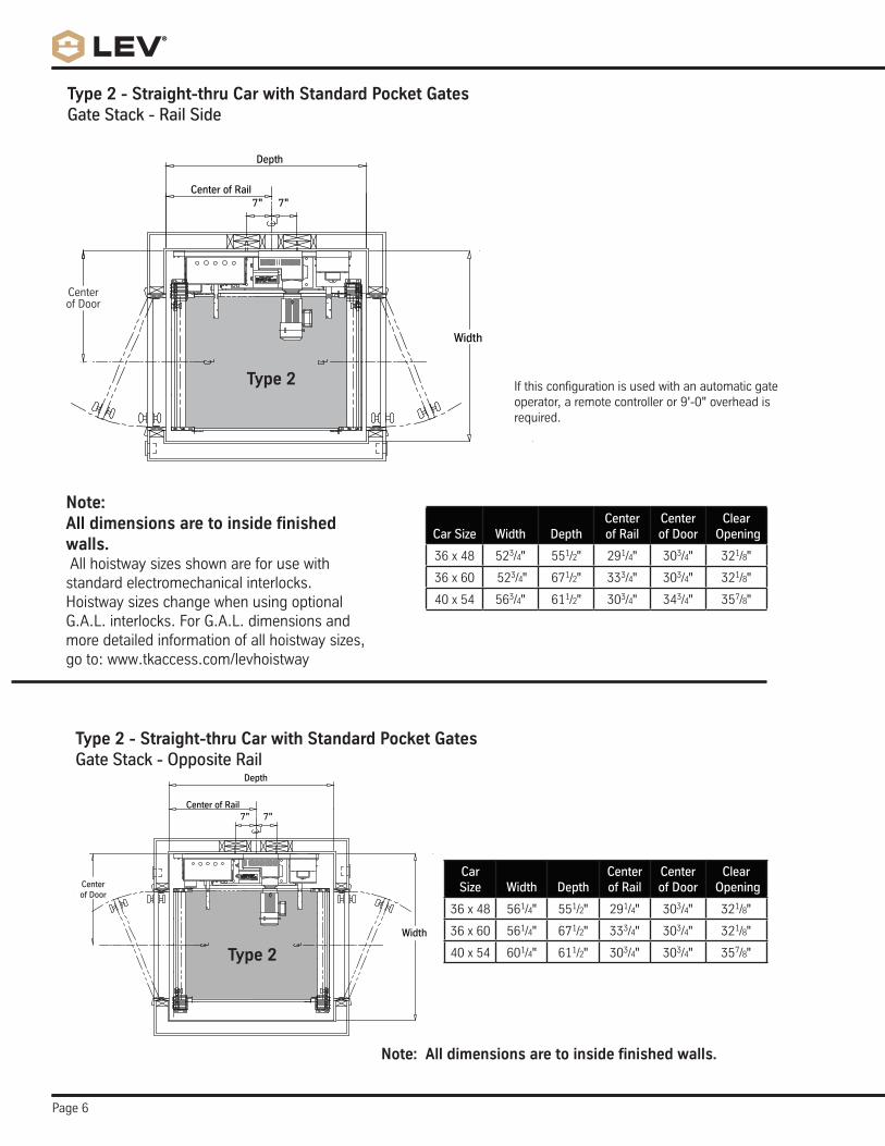
Note: All dimensions are to inside finished walls.
Type 2 - Straight-thru Car with Standard Pocket GatesGate Stack - Opposite Rail
Car Size
Width
Depth
Center of Rail
Center of Door
Clear Opening
36 x 48 561/4" 551/2" 291/4" 303/4" 321/8"
36 x 60 561/4" 671/2" 333/4" 303/4" 321/8"
40 x 54 601/4" 611/2" 303/4" 303/4" 357/8"
Depth
Width
HoistwayCenterline
Center of Rail7" 7"
Type 2
Centerof Door
If this configuration is used with an automatic gate operator,aremotecontrolleror9'-0"overheadisrequired.
Type 2 - Straight-thru Car with Standard Pocket GatesGate Stack - Rail Side
Note: All dimensions are to inside finished walls. All hoistway sizes shown are for use with standard electromechanical interlocks. Hoistway sizes change when using optional G.A.L. interlocks. For G.A.L. dimensions and more detailed information of all hoistway sizes, goto:www.tkaccess.com/levhoistway
Car Size
Width
Depth
Center of Rail
Center of Door
Clear Opening
36 x 48 523/4" 551/2" 291/4" 303/4" 321/8"
36 x 60 523/4" 671/2" 333/4" 303/4" 321/8"
40 x 54 563/4" 611/2" 303/4" 343/4" 357/8"
Depth
Width
HoistwayCenterline
Center of Rail7" 7"
Centerof Door
Type 2
Page 7
Depth
Width
HoistwayCenterline
Center of Rail
7" 7"
Depth
Width
HoistwayCenterline
Center of Rail
7" 7"
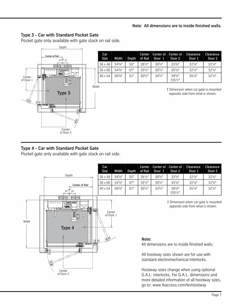
Type 3 - Car with Standard Pocket GatePocket gate only available with gate stack on rail side.
Type 4 - Car with Standard Pocket GatePocket gate only available with gate stack on rail side.
Depth
Center of Door 1
Width
Center of Door 2
Depth
Center of Door 1
Width
Center of Door 2
† Dimension when car gate is mounted opposite side from what is shown.
Note: All dimensions are to inside finished walls.
† Dimension when car gate is mounted opposite side from what is shown.
Type 3
Type 4
Note: All dimensions are to inside finished walls. All hoistway sizes shown are for use with standard electromechanical interlocks. Hoistway sizes change when using optional G.A.L. interlocks. For G.A.L. dimensions and more detailed information of all hoistway sizes, goto:www.tkaccess.com/levhoistway
Car Size
Width
Depth
Center of Rail
Center of Door 1
Center of Door 2
Clearance Door 1
Clearance Door 2
36 x 48 543/8" 55" 261/2" 303/4" 333/8" 321/8" 321/8"
36 x 60 543/8" 67" 331/2" 303/4" 453/8" 321/8" 321/8"
40 x 54 583/8" 61" 301/2" 343/4" 393/8"†351/2"
351/8" 321/8"
Car Size
Width
Depth
Center of Rail
Center of Door 1
Center of Door 2
Clearance Door 1
Clearance Door 2
36 x 48 543/8" 55" 281/2" 303/4" 333/8" 321/8" 321/8"
36 x 60 543/8" 67" 331/2" 303/4" 453/8" 321/8" 321/8"
40 x 54 583/8" 61" 301/2" 343/4" 393/8"†351/2"
351/8" 321/8"
Page 8
Depth
Width
HoistwayCenterline
Center of Rail
7" 7"
Depth
Width
Center of Rail
7" 7"
Depth
Width
HoistwayCenterline
Center of Rail
7" 7"
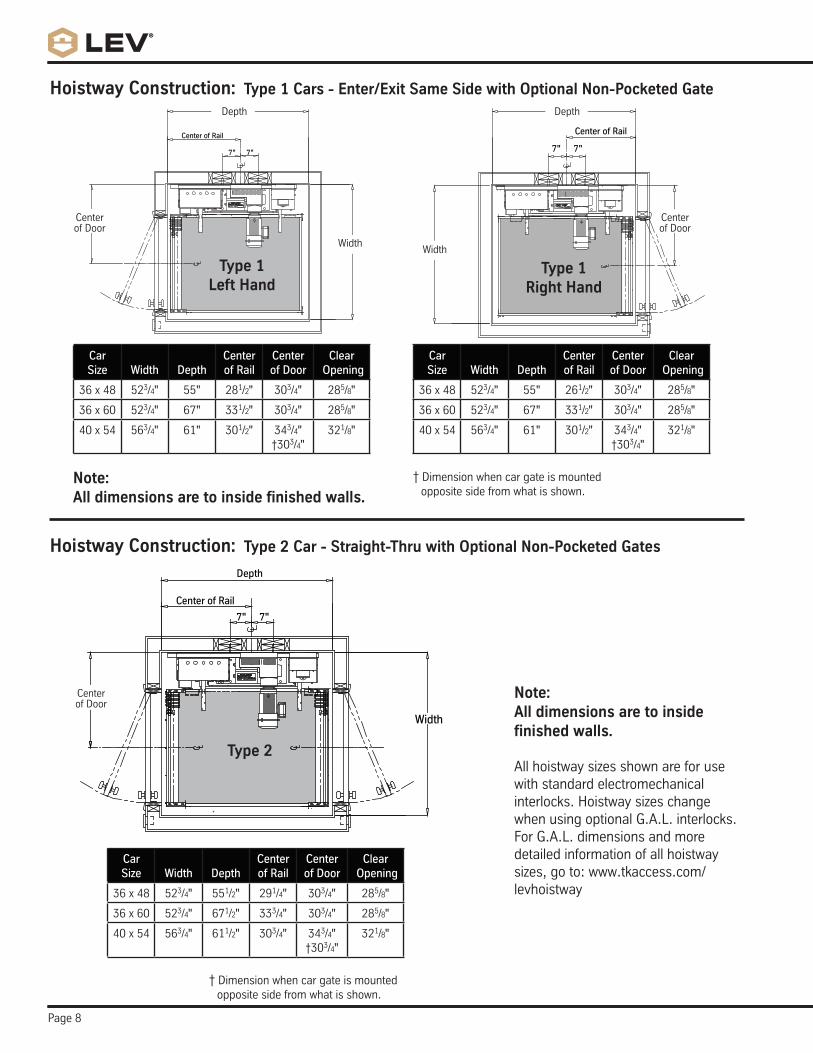
Hoistway Construction: Type 1 Cars - Enter/Exit Same Side with Optional Non-Pocketed Gate
Hoistway Construction: Type 2 Car - Straight-Thru with Optional Non-Pocketed Gates
Center of Door
Type 1Right Hand
Type 1Left Hand
Depth
Center of Door
WidthWidth
Depth
Center of Door
† Dimension when car gate is mounted opposite side from what is shown.
Type 2
† Dimension when car gate is mounted opposite side from what is shown.
Note: All dimensions are to inside finished walls. All hoistway sizes shown are for use with standard electromechanical interlocks. Hoistway sizes change when using optional G.A.L. interlocks. For G.A.L. dimensions and more detailed information of all hoistway sizes,goto:www.tkaccess.com/levhoistway
Car Size
Width
Depth
Center of Rail
Center of Door
Clear Opening
36 x 48 523/4" 55" 261/2" 303/4" 285/8"
36 x 60 523/4" 67" 331/2" 303/4" 285/8"
40 x 54 563/4" 61" 301/2" 343/4"†303/4"
321/8"
Car Size
Width
Depth
Center of Rail
Center of Door
Clear Opening
36 x 48 523/4" 551/2" 291/4" 303/4" 285/8"
36 x 60 523/4" 671/2" 333/4" 303/4" 285/8"
40 x 54 563/4" 611/2" 303/4" 343/4"†303/4"
321/8"
Car Size
Width
Depth
Center of Rail
Center of Door
Clear Opening
36 x 48 523/4" 55" 281/2" 303/4" 285/8"
36 x 60 523/4" 67" 331/2" 303/4" 285/8"
40 x 54 563/4" 61" 301/2" 343/4"†303/4"
321/8"
Note: All dimensions are to inside finished walls.
Page 9
Depth
Width
HoistwayCenterline
Center of Rail
7" 7"
Depth
Width
Center ofDoor
Center of Rail
7" 7"
Center ofDoor
Depth
Depth
Type 3
Type 4
Centerof Door 1
Centerof Door 1
Width
Width
Centerof Door 2
Centerof Door 2
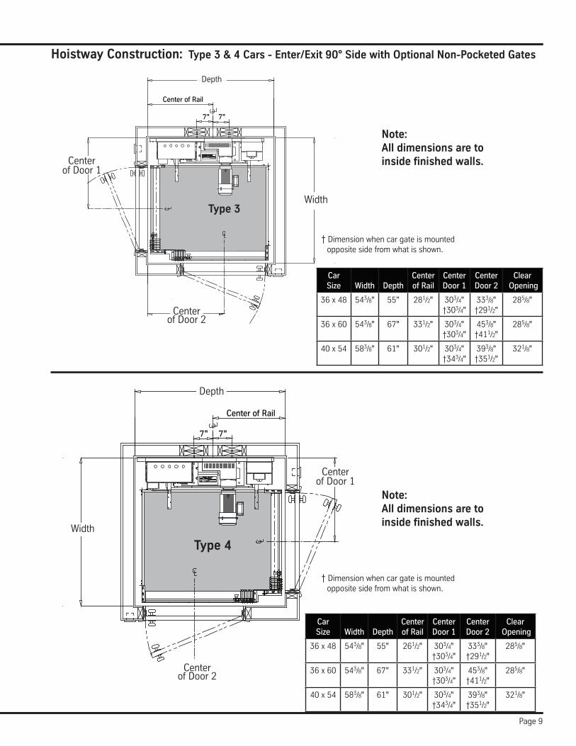
Hoistway Construction: Type 3 & 4 Cars - Enter/Exit 90° Side with Optional Non-Pocketed Gates
Car Size
Width
Depth
Center of Rail
Center Door 1
Center Door 2
Clear Opening
36 x 48 543/8" 55" 281/2" 303/4"†303/4"
333/8"†291/2"
285/8"
36 x 60 543/8" 67" 331/2" 303/4"†303/4"
453/8"†411/2"
285/8"
40 x 54 583/8" 61" 301/2" 303/4"†343/4"
393/8"†351/2"
321/8"
Car Size
Width
Depth
Center of Rail
Center Door 1
Center Door 2
Clear Opening
36 x 48 543/8" 55" 261/2" 303/4"†303/4"
333/8"†291/2"
285/8"
36 x 60 543/8" 67" 331/2" 303/4"†303/4"
453/8"†411/2"
285/8"
40 x 54 583/8" 61" 301/2" 303/4"†343/4"
393/8"†351/2"
321/8"
† Dimension when car gate is mounted opposite side from what is shown.
† Dimension when car gate is mounted opposite side from what is shown.
Note: All dimensions are to inside finished walls.
Note: All dimensions are to inside finished walls.
Page 10
Depth
Width
HoistwayCenterline
Center of Rail
7" 7"
Depth
Width
HoistwayCenterline
Center of Rail
7" 7"
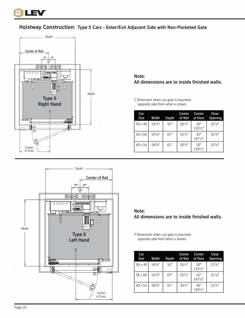
Hoistway Construction: Type 5 Cars - Enter/Exit Adjacent Side with Non-Pocketed Gate
Depth
Depth
Type 5Left Hand
Type 5Right Hand
Width
Width
Center of Door
† Dimension when car gate is mounted opposite side from what is shown.
Car Size
Width
Depth
Center of Rail
Center of Door
Clear Opening
36 x 48 543/8" 55" 261/2" 30" †331/2"
321/8"
36 x 60 543/8" 67" 331/2" 42"†471/2"
321/8"
40 x 54 583/8" 61" 301/2" 36"†391/2"
321/8"
Car Size
Width
Depth
Center of Rail
Center of Door
Clear Opening
36 x 48 543/8" 55" 281/2" 30" †331/2"
321/8"
36 x 60 543/8" 67" 331/2" 42"†471/2"
321/8"
40 x 54 583/8" 61" 301/2" 36"†391/2"
321/8"Center of Door
Note: All dimensions are to inside finished walls.
† Dimension when car gate is mounted opposite side from what is shown.
Note: All dimensions are to inside finished walls.
Page 11
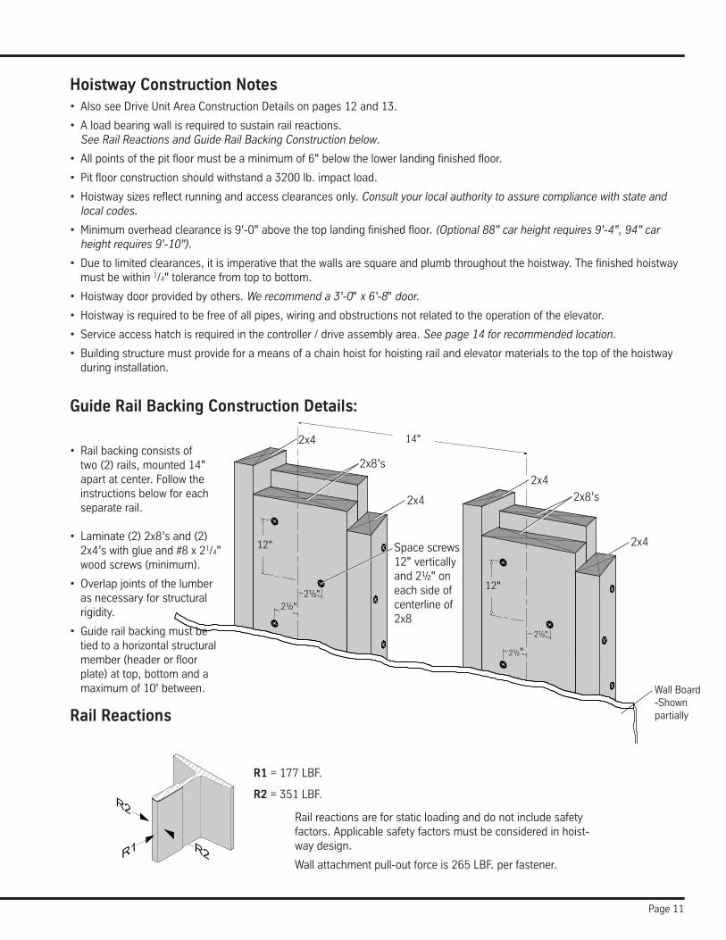
Hoistway Construction Notes• AlsoseeDriveUnitAreaConstructionDetailsonpages12and13.
• Aloadbearingwallisrequiredtosustainrailreactions.See Rail Reactions and Guide Rail Backing Construction below.
• Allpointsofthepitfloormustbeaminimumof6"belowthelowerlandingfinishedfloor.
• Pitfloorconstructionshouldwithstanda3200lb.impactload.
• Hoistwaysizesreflectrunningandaccessclearancesonly.Consult your local authority to assure compliance with state and local codes.
• Minimumoverheadclearanceis9'-0"abovethetoplandingfinishedfloor.(Optional 88" car height requires 9'-4", 94" car height requires 9'-10").
• Duetolimitedclearances,itisimperativethatthewallsaresquareandplumbthroughoutthehoistway.Thefinishedhoistwaymust be within 1/4"tolerancefromtoptobottom.
• Hoistwaydoorprovidedbyothers.We recommend a 3'-0" x 6'-8" door.
• Hoistwayisrequiredtobefreeofallpipes,wiringandobstructionsnotrelatedtotheoperationoftheelevator.
• Serviceaccesshatchisrequiredinthecontroller/driveassemblyarea.See page 14 for recommended location.
• Buildingstructuremustprovideforameansofachainhoistforhoistingrailandelevatormaterialstothetopofthehoistwayduring installation.
Guide Rail Backing Construction Details:
12"
Wall Board-Shown partially
Space screws 12"verticallyand2½"oneach side of centerline of 2x8
• Railbackingconsistsoftwo(2)rails,mounted14"apart at center. Follow the instructions below for each separate rail.
• Laminate(2)2x8’sand(2)2x4’swithglueand#8x21/4"wood screws (minimum).
• Overlapjointsofthelumberas necessary for structural rigidity.
• Guiderailbackingmustbetied to a horizontal structural member(headerorfloorplate) at top, bottom and a maximumof10'between.
2x8’s
2x4
2x4
Rail reactions are for static loading and do not include safety factors. Applicable safety factors must be considered in hoist-way design.
Wall attachment pull-out force is 265 LBF. per fastener.
R1 = 177 LBF.
R2 = 351 LBF.
Rail Reactions
2x8’s
2x4
2x4
12"
2½"2½"
14"
2½"
2½"
Page 12
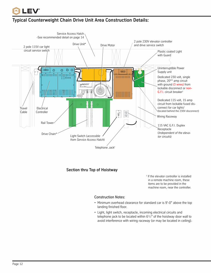
Typical Counterweight Chain Drive Unit Area Construction Details:
Construction Notes:
• Minimumoverheadclearanceforstandardcaris9'-0"abovethetoplandingfinishedfloor.
• Light,lightswitch,receptacle,incomingelectricalcircuitsandtelephone jack to be located within 61/2"ofthehoistwaydoorwalltoavoid interference with wiring raceway (or may be located in ceiling).
Section thru Top of Hoistway
Electrical Controller
Travel Cable
DriveUnit*
Rail Tower
Plastic coated Light with Guard
Light Switch (accessible from Service Access Hatch)
Wiring Raceway
Drive Motor
Dedicated 230 volt, single phase,20**ampcircuitwith ground (3 wires) from lockable disconnect or non-G.F.I. circuit breaker†
Dedicated 115 volt, 15 amp circuit from lockable fused dis-connect for car lights†
(located behind the 230V disconnect)
Telephone Jack†
DriveChain*
2 pole 230V elevator controller and drive service switch2 pole 115V car light
circuit service switch
† If the elevator controller is installed in a remote machine room, these items are to be provided in the machine room, near the controller.
115 VAC G.F.I. Duplex Receptacle(Independent of the eleva-tor circuits)
Service Access Hatch-See recommended detail on page 14
UninterruptiblePower Supply unit
Page 13
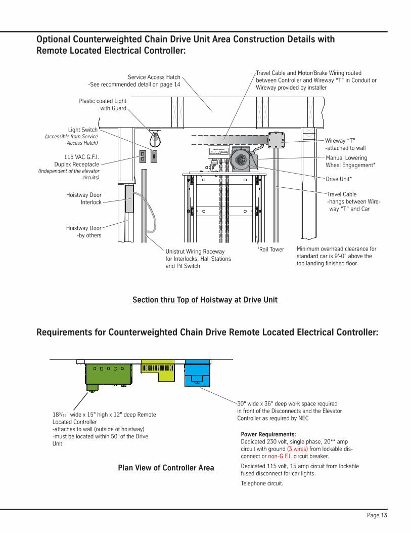
Optional Counterweighted Chain Drive Unit Area Construction Details with Remote Located Electrical Controller:
Requirements for Counterweighted Chain Drive Remote Located Electrical Controller:
Service Access Hatch-See recommended detail on page 14
Travel Cable-hangs between Wire-way “T” and Car
DriveUnit*
Rail Tower
Light Switch (accessible from Service
Access Hatch)
UnistrutWiringRacewayfor Interlocks, Hall Stations and Pit Switch
115 VAC G.F.I. Duplex Receptacle
(Independent of the elevator circuits)
Hoistway Door Interlock
Wireway “T”-attached to wall
Travel Cable and Motor/Brake Wiring routed between Controller and Wireway “T” in Conduit or Wireway provided by installer
Plastic coated Light with Guard
Hoistway Door-by others
Section thru Top of Hoistway at Drive Unit
Plan View of Controller Area
30"widex36"deepworkspacerequiredin front of the Disconnects and the Elevator Controller as required by NEC
Minimum overhead clearance for standardcaris9'-0"abovethetoplandingfinishedfloor.
Power Requirements:Dedicated230volt,singlephase,20**ampcircuit with ground (3 wires) from lockable dis-connect or non-G.F.I. circuit breaker.
Dedicated 115 volt, 15 amp circuit from lockable fused disconnect for car lights.
Telephone circuit.
Manual Lowering WheelEngagement*
183/16"widex15"highx12"deepRemoteLocated Controller-attaches to wall (outside of hoistway)-mustbelocatedwithin50'oftheDriveUnit
Page 14
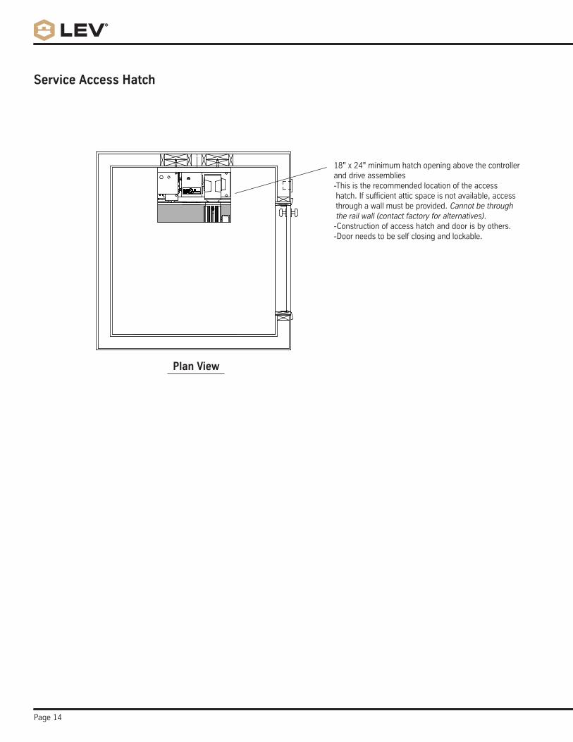
Plan View
18"x24"minimumhatchopeningabovethecontrollerand drive assemblies-This is the recommended location of the access hatch. If sufficient attic space is not available, access through a wall must be provided. Cannot be through the rail wall (contact factory for alternatives).-Construction of access hatch and door is by others.-Door needs to be self closing and lockable.
Service Access Hatch
Page 15
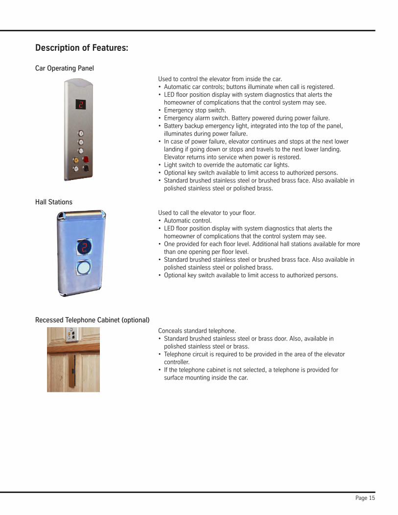
Recessed Telephone Cabinet (optional)
Conceals standard telephone.• Standardbrushedstainlesssteelorbrassdoor.Also,availablein
polished stainless steel or brass.• Telephonecircuitisrequiredtobeprovidedintheareaoftheelevator
controller.• Ifthetelephonecabinetisnotselected,atelephoneisprovidedfor
surface mounting inside the car.
Description of Features:
Car Operating Panel
Usedtocontroltheelevatorfrominsidethecar.• Automaticcarcontrols;buttonsilluminatewhencallisregistered.• LEDfloorpositiondisplaywithsystemdiagnosticsthatalertsthe
homeowner of complications that the control system may see.• Emergencystopswitch.• Emergencyalarmswitch.Batterypoweredduringpowerfailure.• Batterybackupemergencylight,integratedintothetopofthepanel,
illuminates during power failure.• Incaseofpowerfailure,elevatorcontinuesandstopsatthenextlower
landing if going down or stops and travels to the next lower landing. Elevator returns into service when power is restored.• Lightswitchtooverridetheautomaticcarlights.• Optionalkeyswitchavailabletolimitaccesstoauthorizedpersons.• Standardbrushedstainlesssteelorbrushedbrassface.Alsoavailablein
polished stainless steel or polished brass.
Hall Stations
Usedtocalltheelevatortoyourfloor.• Automaticcontrol.• LEDfloorpositiondisplaywithsystemdiagnosticsthatalertsthe
homeowner of complications that the control system may see.• Oneprovidedforeachfloorlevel.Additionalhallstationsavailableformorethanoneopeningperfloorlevel.• Standardbrushedstainlesssteelorbrushedbrassface.Alsoavailablein
polished stainless steel or polished brass.• Optionalkeyswitchavailabletolimitaccesstoauthorizedpersons.
Page 16
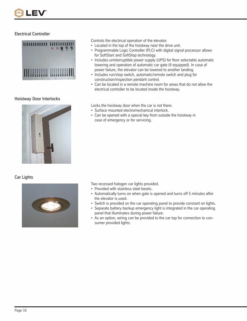
Hoistway Door Interlocks
Locks the hoistway door when the car is not there.• Surfacemountedelectromechanicalinterlock.• Canbeopenedwithaspecialkeyfromoutsidethehoistwayin
case of emergency or for servicing.
Electrical Controller
Controls the electrical operation of the elevator.• Locatedinthetopofthehoistwaynearthedriveunit.• ProgrammableLogicController(PLC)withdigitalsignalprocessorallows
for SoftStart and SoftStop technology.• Includesuninterruptiblepowersupply(UPS)forfloorselectableautomatic
lowering and operation of automatic car gate (if equipped). In case of power failure, the elevator can be lowered to another landing.• Includesrun/stopswitch,automatic/remoteswitchandplugfor
construction/inspection pendant control.• Canbelocatedinaremotemachineroomforareasthatdonotallowthe
electrical controller to be located inside the hoistway.
Car Lights
Two recessed halogen car lights provided.• Providedwithstainlesssteelbezels.• Automaticallyturnsonwhengateisopenedandturnsoff5minutesafter
the elevator is used.• Switchisprovidedonthecaroperatingpaneltoprovideconstantonlights.• Separatebatterybackupemergencylightisintegratedinthecaroperating
panel that illuminates during power failure.• Asanoption,wiringcanbeprovidedtothecartopforconnectiontocon-
sumer provided lights.
Page 17
Description of Features continued:
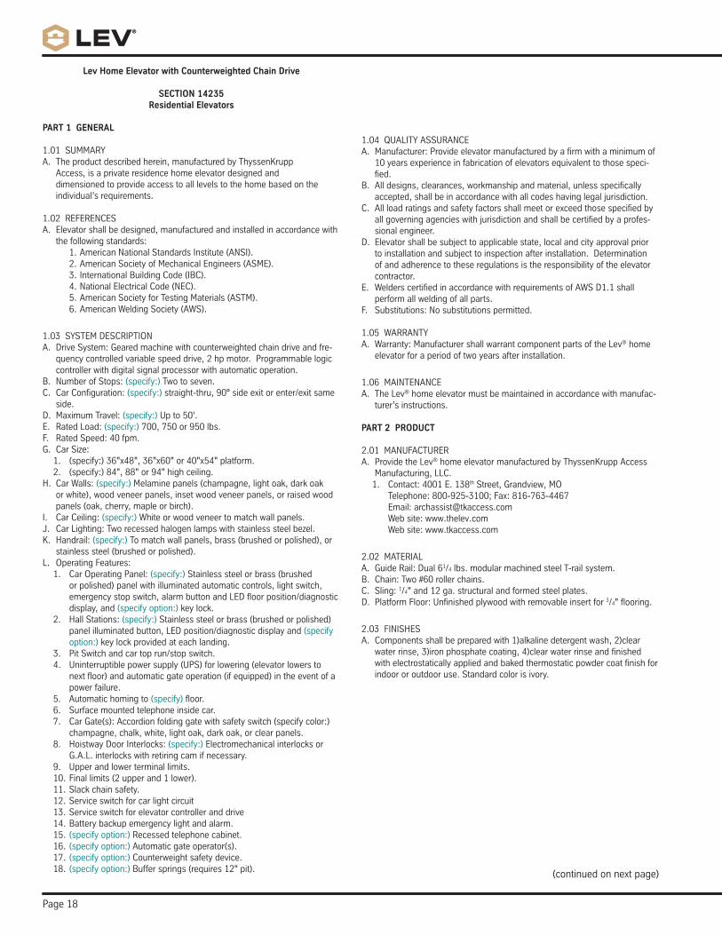
Auto-Opener™ (optional)
Automaticallyopenshoistwaydoorwhencarstopsatafloor.• Mountstowallneartopofdooronthehingeside.Backingis
required by contractor.• Worksinconjunctionwiththeautomaticcargateoperator.• Automaticallyreverseswhenanobstructionisencountered.• Ifcarisalreadyatfloorlevel,doorcanbeopenedbypressinghall
station button.• Requires115VACoutletnearthetopofthedooronthehingeside
at each landing.
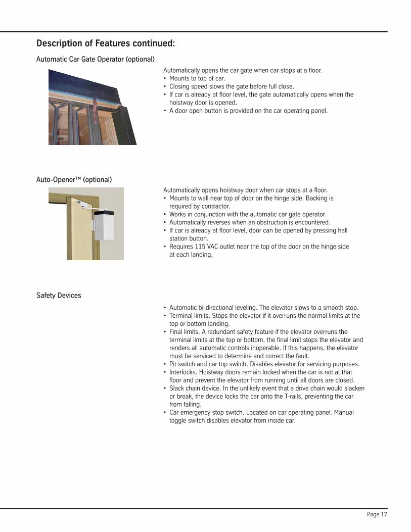
Automatic Car Gate Operator (optional)
Automaticallyopensthecargatewhencarstopsatafloor.• Mountstotopofcar.• Closingspeedslowsthegatebeforefullclose.• Ifcarisalreadyatfloorlevel,thegateautomaticallyopenswhenthe
hoistway door is opened.• Adooropenbuttonisprovidedonthecaroperatingpanel.
• Automaticbi-directionalleveling.Theelevatorslowstoasmoothstop.• Terminallimits.Stopstheelevatorifitoverrunsthenormallimitsatthe
top or bottom landing.• Finallimits.Aredundantsafetyfeatureiftheelevatoroverrunsthe
terminal limits at the top or bottom, the final limit stops the elevator and renders all automatic controls inoperable. If this happens, the elevator must be serviced to determine and correct the fault.• Pitswitchandcartopswitch.Disableselevatorforservicingpurposes.• Interlocks.Hoistwaydoorsremainlockedwhenthecarisnotatthatfloorandpreventtheelevatorfromrunninguntilalldoorsareclosed.• Slackchaindevice.Intheunlikelyeventthatadrivechainwouldslacken
or break, the device locks the car onto the T-rails, preventing the car from falling.• Caremergencystopswitch.Locatedoncaroperatingpanel.Manual
toggle switch disables elevator from inside car.
Safety Devices
Page 18
Lev Home Elevator with Counterweighted Chain Drive
SECTION 14235Residential Elevators
PART 1 GENERAL 1.01SUMMARYA. The product described herein, manufactured by ThyssenKrupp
Access, is a private residence home elevator designed and dimensioned to provide access to all levels to the home based on the individual’s requirements.
1.02 REFERENCESA. Elevator shall be designed, manufactured and installed in accordance with thefollowingstandards:
1. American National Standards Institute (ANSI).2. American Society of Mechanical Engineers (ASME).3. International Building Code (IBC).4. National Electrical Code (NEC).5. American Society for Testing Materials (ASTM).6. American Welding Society (AWS).
1.03SYSTEMDESCRIPTIONA. DriveSystem:Gearedmachinewithcounterweightedchaindriveandfre-
quency controlled variable speed drive, 2 hp motor. Programmable logic controller with digital signal processor with automatic operation.
B. NumberofStops:(specify:) Two to seven.C. CarConfiguration:(specify:) straight-thru, 90° side exit or enter/exit same
side.D. MaximumTravel:(specify:)Upto50'.E. RatedLoad:(specify:) 700, 750 or 950 lbs.F. RatedSpeed:40fpm.G. CarSize:1. (specify:)36"x48",36"x60"or40"x54"platform.2. (specify:)84",88"or94"highceiling.
H. CarWalls:(specify:) Melamine panels (champagne, light oak, dark oak or white), wood veneer panels, inset wood veneer panels, or raised wood panels (oak, cherry, maple or birch).
I. CarCeiling:(specify:) White or wood veneer to match wall panels.J. CarLighting:Tworecessedhalogenlampswithstainlesssteelbezel.K. Handrail:(specify:) To match wall panels, brass (brushed or polished), or
stainless steel (brushed or polished).L. OperatingFeatures:1. CarOperatingPanel:(specify:) Stainless steel or brass (brushed
or polished) panel with illuminated automatic controls, light switch, emergencystopswitch,alarmbuttonandLEDfloorposition/diagnosticdisplay, and (specifyoption:) key lock.
2. HallStations:(specify:) Stainless steel or brass (brushed or polished) panel illuminated button, LED position/diagnostic display and (specify option:) key lock provided at each landing.
3. Pit Switch and car top run/stop switch.4. Uninterruptiblepowersupply(UPS)forlowering(elevatorlowerstonextfloor)andautomaticgateoperation(ifequipped)intheeventofapower failure.
5. Automatic homing to (specify)floor.6. Surface mounted telephone inside car.7. CarGate(s):Accordionfoldinggatewithsafetyswitch(specifycolor:)
champagne, chalk, white, light oak, dark oak, or clear panels.8. HoistwayDoorInterlocks:(specify:) Electromechanical interlocks or
G.A.L. interlocks with retiring cam if necessary.9. Upperandlowerterminallimits.10. Final limits (2 upper and 1 lower).11. Slack chain safety.12. Service switch for car light circuit13. Service switch for elevator controller and drive14. Battery backup emergency light and alarm.15. (specifyoption:) Recessed telephone cabinet.16. (specifyoption:) Automatic gate operator(s).17. (specifyoption:) Counterweight safety device.18. (specifyoption:)Buffersprings(requires12"pit).
1.04QUALITYASSURANCEA. Manufacturer:Provideelevatormanufacturedbyafirmwithaminimumof
10 years experience in fabrication of elevators equivalent to those speci-fied.
B. All designs, clearances, workmanship and material, unless specifically accepted, shall be in accordance with all codes having legal jurisdiction.
C. All load ratings and safety factors shall meet or exceed those specified by all governing agencies with jurisdiction and shall be certified by a profes-sional engineer.
D. Elevator shall be subject to applicable state, local and city approval prior to installation and subject to inspection after installation. Determination of and adherence to these regulations is the responsibility of the elevator contractor.
E. Welders certified in accordance with requirements of AWS D1.1 shall perform all welding of all parts.
F. Substitutions:Nosubstitutionspermitted. 1.05WARRANTYA. Warranty:ManufacturershallwarrantcomponentpartsoftheLev® home
elevator for a period of two years after installation.
1.06 MAINTENANCEA. The Lev® home elevator must be maintained in accordance with manufac-
turer’s instructions.
PART 2 PRODUCT
2.01MANUFACTURERA. Provide the Lev® home elevator manufactured by ThyssenKrupp Access
Manufacturing, LLC.1. Contact:4001E.138th Street, Grandview, MOTelephone:800-925-3100;Fax:816-763-4467 Email:[email protected]:www.thelev.comWebsite:www.tkaccess.com
2.02 MATERIALA. GuideRail:Dual61/4 lbs. modular machined steel T-rail system.B. Chain:Two#60rollerchains.C. Sling:1/4"and12ga.structuralandformedsteelplates.D. PlatformFloor:Unfinishedplywoodwithremovableinsertfor3/4"flooring.
2.03 FINISHESA. Components shall be prepared with 1)alkaline detergent wash, 2)clear
water rinse, 3)iron phosphate coating, 4)clear water rinse and finished with electrostatically applied and baked thermostatic powder coat finish for indoor or outdoor use. Standard color is ivory.
(continued on next page)
Page 19
2.04ELECTRICALSYSTEMSA. Theelectricalcontractorsshallprovide:
1. 230 VAC, 20 amp, 60 Hz, single phase power source with ground (3 wires) in the controller area.
2. 115 VAC, single phase, 15 amp, 60 Hz power circuit in the controller area for the car lights.
3. Telephone circuit in the controller area.
PART 3 EXECUTION
3.01 ACCEPTABLE INSTALLERSA. Installers shall be experienced in performing work of this section who have
specialized in work comparable to that required for this project.B. Installers shall be certified and trained by the manufacturer.
3.02 EXAMINATIONA. Usefielddimensionsandapprovedmanufacturer’sshopdrawingstoex-
amine substrates, supports and other conditions under which this work is to be performed. Do not proceed with work until unsatisfactory conditions are corrected.
3.03 INSTALLATIONA. The Lev® home elevator shall be installed in accordance with manufac-
turer’s instructions and as specified and approved by architect. B. Hoistway doors shall be installed by others.
3.04 DEMONSTRATIONA. The elevator contractor shall make a final check of the elevator’s operation
with the Owner or Owner’s representative present prior to turning the el-evator over for use. The elevator contractor shall determine that operating and safety devices are functioning properly.
END OF SECTION
Notes:Intentofspecificationistobroadlyoutlineequipmentrequiredbutdoes not cover details of design and construction. Dimensions and specifications are subject to constant change and continually evolving codes and product applications. For additional technical information, contact ThyssenKrupp Access Manufacturing, LLC at (800) 925-3100 or www.tkaccess.com.
(continued on next page)
Page 20
Lev Home Elevator with Signet Cab (Counterweighted Chain Drive)
SECTION 14235Residential Elevators
PART 1 GENERAL 1.01SUMMARYA. The product described herein, manufactured by ThyssenKrupp
Access, is a private residence home elevator designed and dimensioned to provide access to all levels to the home based on the individual’s requirements.
1.02 REFERENCESA. Elevator shall be designed, manufactured and installed in accordance with thefollowingstandards:
1. American National Standards Institute (ANSI).2. American Society of Mechanical Engineers (ASME).3. International Building Code (IBC).4. National Electrical Code (NEC).5. American Society for Testing Materials (ASTM).6. American Welding Society (AWS).
1.03SYSTEMDESCRIPTIONA. DriveSystem:Gearedmachinewithcounterweightedchaindriveand
frequency controlled variable speed drive, 2 hp motor. Programmable logic controller with digital signal processor with automatic operation.
B. NumberofStops:(specify:) Two to seven.C. CarConfiguration:(specify:) straight-thru, 90° side exit or enter/exit same
side.D. MaximumTravel:(specify:)Upto50'.E. RatedLoad:(specify:) 700, 750 or 950 lbs.F. RatedSpeed:40fpm.G. CarSize:
1. (specify:)36"x48",36"x60"or40"x54"platform.2. (specify:)84",88"or94"highceiling.
H. CarWalls:(specify:) Metal frame with upper panel of glass, metal, laminate, stone or wood, lower panel of glass, metal, laminate, stone or wood.
I. CarCeiling:(specify:) Custom metal, laminate or wood.J. CarLighting:(specify:) Two or four halogen lamps.K. Handrail:(specify:) Stainless steel or bronze (polished, brushed or
decorative).L. OperatingFeatures:1. CarOperatingPanel:(specify:) custom metal, laminate or wood full lengthpanelwithflushmountedilluminatedautomaticcontrols,lightswitch,emergencystopswitch,alarmbuttonandLEDfloorposition/diagnostic display, and (specifyoption:) key lock.
2. HallStations:(specify:) Stainless steel or brass (brushed or polished) panel illuminated button, LED position/diagnostic display and (specify option:) key lock provided at each landing.
3. Pit Switch and car top run/stop switch.4. Uninterruptiblepowersupply(UPS)forlowering(elevatorlowerstonextfloor)andautomaticgateoperationintheeventofapowerfailure.
5. Automatic homing to (specify)floor.6. Telephone inside recessed telephone cabinet in car.7. CarGate(s):Accordionfoldinggatewithsafetyswitch(specifycolor:)
champagne, chalk, white, light oak, dark oak, or clear panels.8. HoistwayDoorInterlocks:(specify:) Electromechanical interlocks or
G.A.L. interlocks with retiring cam if necessary.9. Upperandlowerterminallimits.10. Final limits (2 upper and 1 lower).11. Slack chain safety.12. Service switch for car light circuit
13. Service switch for elevator controller and drive14. Battery backup emergency light and alarm.15. Recessed telephone cabinet.16. Automatic gate operator(s).17. (specifyoption:) Counterweight safety device.18. (specifyoption:)Buffersprings(requires12"pit).
1.04QUALITYASSURANCEA. Manufacturer:Provideelevatormanufacturedbyafirmwithaminimum
of 10 years experience in fabrication of elevators equivalent to those specified.
B. All designs, clearances, workmanship and material, unless specifically accepted, shall be in accordance with all codes having legal jurisdiction.
C. All load ratings and safety factors shall meet or exceed those specified by all governing agencies with jurisdiction and shall be certified by a professional engineer.
D. Elevator shall be subject to applicable state, local and city approval prior to installation and subject to inspection after installation. Determination of and adherence to these regulations is the responsibility of the elevator contractor.
E. Welders certified in accordance with requirements of AWS D1.1 shall perform all welding of all parts.
F. Substitutions:Nosubstitutionspermitted. 1.05WARRANTYA. Warranty:ManufacturershallwarrantcomponentpartsoftheLev® Signet
home elevator for a period of two years after installation.
1.06 MAINTENANCEA. The Lev® Signet home elevator must be maintained in accordance with
manufacturer’s instructions.
PART 2 PRODUCT
2.01MANUFACTURERA. Provide the Lev® Signet home elevator manufactured by
ThyssenKrupp Access Manufacturing, LLC.1. Contact:4001E.138th Street, Grandview, MOTelephone:800-925-3100;Fax:816-763-4467 Email:[email protected]:www.thelev.comWebsite:www.tkaccess.com
2.02 MATERIALA. GuideRail:Dual61/4 lbs. modular machined steel T-rail system.B. Chain:Two#60rollerchains.C. Sling:1/4"and12ga.structuralandformedsteelplates.D. PlatformFloor:Unfinishedplywoodwithremovableinsertfor3/4"flooring.
2.03 FINISHESA. Components shall be prepared with 1)alkaline detergent wash, 2)clear
water rinse, 3)iron phosphate coating, 4)clear water rinse and finished with electrostatically applied and baked thermostatic powder coat finish for indoor or outdoor use. Standard color is ivory.
LEV Signet Home Elevator
(continued on next page)
Page 21
2.04ELECTRICALSYSTEMSA. Theelectricalcontractorsshallprovide:
1. 230 VAC, 20 amp, 60 Hz, single phase power source with ground (3 wires) in the controller area.
2. 115 VAC, single phase, 15 amp, 60 Hz power circuit in the controller area for the car lights.
3. Telephone circuit in the controller area.
PART 3 EXECUTION
3.01 ACCEPTABLE INSTALLERSA. Installers shall be experienced in performing work of this section who have
specialized in work comparable to that required for this project.B. Installers shall be certified and trained by the manufacturer.
3.02 EXAMINATIONA. Usefielddimensionsandapprovedmanufacturer’sshopdrawingstoex-
amine substrates, supports and other conditions under which this work is to be performed. Do not proceed with work until unsatisfactory conditions are corrected.
3.03 INSTALLATIONA. The Lev® Signet home elevator shall be installed in accordance with manu-
facturer’s instructions and as specified and approved by architect. B. Hoistway doors shall be installed by others.
3.04 DEMONSTRATIONA. The elevator contractor shall make a final check of the elevator’s operation
with the Owner or Owner’s representative present prior to turning the el-evator over for use. The elevator contractor shall determine that operating and safety devices are functioning properly.
END OF SECTION
Notes:Intentofspecificationistobroadlyoutlineequipmentrequiredbutdoes not cover details of design and construction. Dimensions and specifications are subject to constant change and continually evolving codes and product applications. For additional technical information, contact ThyssenKrupp Access Manufacturing, LLC at (800) 925-3100 or www.tkaccess.com.
LEV Signet Home Elevator
Page 22
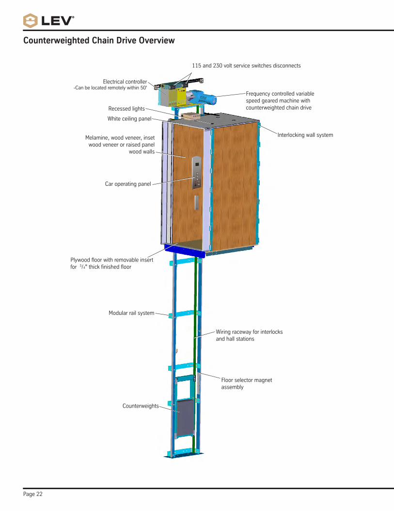
Counterweighted Chain Drive Overview
Frequency controlled variable speed geared machine with counterweighted chain drive
Electrical controller-Canbelocatedremotelywithin50'
Car operating panel
Recessed lights
Counterweights
Floor selector magnet assembly
Modular rail system
Wiring raceway for interlocks and hall stations
White ceiling panel
Melamine, wood veneer, inset wood veneer or raised panel
wood walls
Interlocking wall system
Plywoodfloorwithremovableinsertfor 3/4"thickfinishedfloor
115 and 230 volt service switches disconnects

Page 23

Page 24
ThyssenKrupp Access Manufacturing, LLC4001 East 138th Street
Grandview, MO 64030-2837Phone: 816-763-3100
Fax: 816-763-4467Sales: 800-669-9047
www.thelev.comwww.tkaccess.com0210-IM398