Embed Size (px)
Citation preview

TK
ThyssenKrupp ElevatorAmericas Business Unit
traction elevators2008 planning guide
Traction_07_14_08.indd 1Traction_07_14_08.indd 1 7/21/08 4:57:17 PM7/21/08 4:57:17 PM

2
Our Commitment To You
Design, Performance, Dependability
At ThyssenKrupp Elevator, we believe in the critical importance of listening to our customers. While technological expertise makes our products and services possible, we know that listening to our customers is what keeps us at the top of our industry. That’s because our commitment to listening leads to the innovations that satisfy our customers’ needs, driving us continually to set new standards for elevator performance and reliability.
Because we always listen to our customers, they have come to regard ThyssenKrupp Elevator as an integral part of their projects. In addition to their confidence in the quality of our products, they know that each of our standard-sized passenger elevators meets the requirements of the Americans with Disabilities Act (ADA) and that we will modify our elevators to comply with local fire service codes. Perhaps most of all, customers rely on our nationwide network of service locations. And even if your building is remotely located, no point in the U.S. is more than 75 miles from a ThyssenKrupp Elevator service technician.
Geared and Gearless Traction Elevators
In the field of traction systems, ThyssenKrupp Elevator’s designers and engineers push their technological creativity to its full potential. Whether geared or gearless, our traction elevators combine the latest digital technology with world-renowned manufacturing expertise to achieve a new level of precision, energy efficiency, safety and reliability.
For buildings of up to twenty-seven floors, ThyssenKrupp Elevator’s complete line of SPF geared traction elevators are known for their smooth, quick acceleration, high energy efficiency and competitive pricing. ThyssenKrupp Elevator’s gearless systems for high-rise buildings are famous for their versatility, power and, above all, speed.
Geared or gearless, all of our traction systems utilize the advanced vector control technology of our all-digital centralized microprocessor control systems to move a lot of people in amazingly little time.
Table of Contents
Architect Direct Pro. . . . . . . . . . . . . . . . . . . . . . . . . . 2SPF Traction Elevators Passenger, with Front Openings. . . . . . . . . . . . . . . 3 Passenger, with Front and Rear Openings . . . . . . . 4SPF Traction Elevators For Patient Care Facilities . . . . 5AC Gearless Traction Elevators For High-Rise Buildings Custom-Engineered Passenger, Up To 700 fpm . . . 6 Custom-Engineered Passenger, Up To 1200 fpm . . 7Cab Design . . . . . . . . . . . . . . . . . . . . . . . . . . . . . 8-9TK Entrances Details. . . . . . . . . . . . . . . . . . . . . . . . 10Work Not Included . . . . . . . . . . . . . . . . . . . . . . . . . 11
Architect Direct ProPro
When you’re putting together a proposal, we know you don’t have all day to spend on elevator selection. So we’ve created a solution that enables you to find the right elevator - and get specifications and drawings - as fast as a few clicks of the mouse.
This solution is Architect Direct Pro and you’ll find it at thyssenkruppelevator.com. All you have to do is answer a few questions about your building, and Architect Direct Pro will tell you which of our standard elevators is best suited to your project. It’s that easy.
You’ll probably want specifications. With a few more clicks, Architect Direct Pro will compile a complete specifications document ready for download in Microsoft Word.
For more information, please contact your local ThyssenKrupp Elevator representative or visit www.thyssenkruppelevator.com.
Traction_07_14_08.indd 2Traction_07_14_08.indd 2 7/21/08 4:57:20 PM7/21/08 4:57:20 PM

3Note: All dimensions in parentheses are in millimeters unless otherwise indicated. Dimensional data shown here complies with the current ASME A17.1 and CSA B44 Safety Code for Elevators. Local codes may vary from the national codes. Consult your local ThyssenKrupp Elevator representative for details.
SPF Traction ElevatorsPassenger Elevators with Front Entrances
Safety beam by others
LTemperature range 50˚F (28°C) min.90˚F (50°C) max.10-90% Non-Condensing Relative
Humidity
7'-6
" (2
286)
Trav
el
Ladder to pitby others
OP
7'-0
" (2
134)
7'-0
" (2
134)
7'-1
1" (
2413
)
S
Right hand door shown: left hand available
G4" (102)Rough sill
4" (102)Rough sill
AC
D
F
B
AC
D
4"(102)
E
S = Concrete structural support slab by others. Machine room floor to support all elevator machine loads and floor loads per ASME A17.1.
1 Clear inside dimensions. 2 Single car dimensions (Add 4” (102) for seismic).3 Add 2” (51) for seismic. 4 Two car dimensions (Add 8” (203) for seismic).5 Center opening not available on this model, see “G” for dimensions.6 The door sizes shown comply with 2006 IBC code requirements.
Capacity in pounds
4’-3” (1295)
Dimensions
SPF-21 SPF-25 SPF-30
4’-3” (1295) 4’-9” (1448)
2100 (953 kg) 2500 (1134 kg) 3000 (1361 kg)
5’-8” (1727) 6’-8” (2032) 6’-8” (2032)
SPF-35
5’-5” (1651)
3500 (1588 kg)
6’-8” (2032)
5’-5” (1651)
4000 (1814 kg)
7’-8” (2337)A1
B1
C
D2
E3
F4
G
7’-4” (2235) 8’-4” (2540) 8’-4” (2540)
N/A5 3’-6” (1067) 3’-6” (1067)
8’-4” (2540)
3’-6” (1067)
9’-4” (2845)
4’-0” (1219)6
15’-0” (4572) 17’-0” (5182) 17’-0” (5182)
6’-8” (2032) 6’-8” (2032) 7’-2” (2184)
17’-0” (5182)
7’-10” (2388)
19’-0” (5791)
7’-10” (2388)
3’-0” (914) 3’-6” (1067) 3’-6” (1067) 3’-6” (1067) 3’-6” (1067)6
7 Consult ThyssenKrupp Elevator for pit with travel over 250’-0” (76200).NOTE: Hoistway dimensions are based on 1” (25) out of plumb and no occupied space below hoistway. If these conditions cannot be met, then consideration must be given for additional required space.* 5’-9” Pit may be required for 2000 code compliance, if 48” retractable toe guard not used.
Speed feet per minute (fpm)
Minimum pit, overhead and machine room dimensions
Capacity in lbs.
2100 (953 kg)
2500 (1134 kg)
3000 (1361 kg)
3500 (1588 kg)
4000 (1814 kg)
O
Dimensions
L
P7
L
P7
O
O
L
P7
L
P7
O
O
L
P7
450/500 (2.2/2.5m/s)
N/A
N/A
N/A
16’-0” (4877)
6’-6” (1981)
16’-0” (4877)
16’-0” (4877)
16’-0” (4877)
6’-6” (1981)
16’-0” (4877)
6’-6” (1981)
17’-2” (5232)
N/A
N/A
N/A
200 (1.0m/s)
15’-0” (4572)
16’-0” (4877)
5’-0” (1524)*
15’-0” (4572)
16’-0” (4877)
5’-0” (1524)*
15’-0” (4572)
16’-0” (4877)
5’-0” (1524)*
15’-0” (4572)
16’-0” (4877)
5’-0” (1524)*
15’-0” (4572)
16’-0” (4877)
5’-0” (1524)*
350 (1.7m/s)
16’-0” (4877)
15’-0” (4572)
5’-0” (1524)*
16’-0” (4877)
15’-0” (4572)
5’-0” (1524)*
16’-0” (4877)
15’-8” (4775)
5’-0” (1524)*
16’-0” (4877)
15’-8” (4775)
5’-0” (1524)*
16’-0” (4877)
16’-0” (4877)
5’-0” (1524)*
Geared
SPF-40(IBC)
Traction_07_14_08.indd 3Traction_07_14_08.indd 3 7/21/08 4:57:20 PM7/21/08 4:57:20 PM

4Note: All dimensions in parentheses are in millimeters unless otherwise indicated. Dimensional data shown here complies with the current ASME A17.1 and CSA B44 Safety
Code for Elevators. Local codes may vary from the national codes. Consult your local ThyssenKrupp Elevator representative for details.
SPF Traction ElevatorsPassenger Elevators with Front and Rear Entrances
4" (102)Rough sillA
C
DF
B
AC
D
4"(102)
4" (102)Rough sill
E
Speed feet per minute (fpm)
O
Capacity in lbs.
2500 (1134 kg)
Minimum pit, overhead and machine room dimensions
Dimensions 200 (1.0m/s) 350 (1.7m/s)
L
450/500 (2.2/2.5m/s)
P4
16’-0” (4877) 16’-0” (4877)
4 6’-0” (1829) min. “P” above 110’-0” (33528) travel. Consult ThyssenKrupp Elevator for travel over 250’-0” (76200).* 5’-9” Pit may be required for 2000 code compliance, if 48” retractable toe guard not used.
5’-0” (1524)* 6’-6” (1981)
16’-0” (4877) 16’-0” (4877)
15’-8” (4775) 16’-0” (4877)
15’-0” (4572) 16’-0” (4877)
16’-0” (4877)
O
3000 (1361 kg) L
P4
O
3500 (1588 kg) L
P4
15’-0” (4572)
5’-0” (1524)*
16’-0” (4877)
15’-0” (4572)
5’-0” (1524)* 6’-6” (1981)5’-0” (1524)*
16’-0” (4877) 16’-0” (4877)
17’-2” (5232)
16’-0” (4877)
5’-0” (1524)* 6’-6” (1981)5’-0” (1524)*
15’-8” (4775)15’-0” (4572)
L
8'-9
" (2
667)
7'-0
" (2
134)
OP
7'-1
1" (
2413
)
Safety beamby others
Trav
el
Ladder to pitby others
7'-0
" (2
134)
S
Temperature range 50˚F (28˚C) min.90˚F (50˚C) max.10-90% Non-CondensingRelative Humidity
S = Concrete structural support slab by others. Machine room floor to support all elevator machine loads and floor loads per ASME A17.1.
ThyssenKrupp Elevator offers a complete line of SPF geared traction elevators that can serve up to 27 landings. Our SPF line offers superb performance in office buildings, apartment complexes, dormitories, hotels and other structures. These elevators offer you standard design data, quick layout and fast delivery.
Capacity in lbs.
Dimensions
A1
SPF-25 SPF-30 SPF-35
2500 (1134 kg) 3000 (1361 kg) 3500 (1588 kg)
6’-8” (2032) 6’-8” (2032) 6’-8” (2032)
B1
C
D2
E
F3
1 Clear inside dimensions.2 Single car dimensions (Add 6” (152) for seismic).3 Two car dimensions (Add 12” (305) for seismic).NOTE: Hoistway dimensions are based on 1” (25) out of plumb and no occupied space below hoistway. If these conditions cannot be met, then consideration must be given for additional required space.
Plan 2 Plan 2 Plan 2
3’-6” (1067) 3’-6” (1067) 3’-6” (1067)
9’-2” (2794) 9’-2” (2794) 9’-2” (2794)
6’-83/4” (2051) 7’-23/4” (2203) 7’-103/4” (2407)
18’-8” (5690) 18’-8” (5690) 18’-8” (5690)
4’-31/2” (1308) 4’-91/2” (1461) 5’-51/2” (1664)
G 3’-6” (1067) 3’-6” (1067) 3’-6” (1067)
Right hand door shown: left hand available
G4" (102)Rough sill
Traction_07_14_08.indd 4Traction_07_14_08.indd 4 7/21/08 4:57:20 PM7/21/08 4:57:20 PM

5Note: All dimensions in parentheses are in millimeters unless otherwise indicated. Dimensional data shown here complies with the current ASME A17.1 and CSA B44 Safety Code for Elevators. Local codes may vary from the national codes. Consult your local ThyssenKrupp Elevator representative for details.
SPF Traction ElevatorsFor Patient-Care Facilities
L
W
7'-0
" (2
134)
OP
Rea
r en
tran
ce a
vaila
ble
7'-1
1" (
2413
)
Safety beamby others
Trav
el
Ladder to pitby others
7'-0
" (2
134)
S
Temperature range 50˚F (28˚C) min.90˚F (50˚C) max. 10-90% Non-CondensingRelative Humidity
AD
C
DAC
Plan 1 Plan 2
F
BE B E
C 51/2" (140)Rough sill
Two-speed doors - both right and left hand available
51/2" (140)Rough sill4"
(102)
Our SPF-45, SPF-50 and SPF-50H elevators offer economical, dependable service for hospitals, nursing homes and intermediate care facilities. The car shape makes it ideal for use in any building where the elevator performs a dual role for passengers and service. The SPF-50H is now the standard size hospital car set forth to meet AIA requirements.
S = Concrete structural support slab by others. Machine room floor to support all elevator machine loads and floor loads per ASME A17.1.W = 7’-6” (2286) [8’-0” (2438) for 5000 @ 450 and 6000 at all duties].
Speed feet per minute (fpm)
O
Capacity in lbs.
4500 (2041 kg)
Minimum pit, overhead and machine room dimensions
Dimensions 200 (1.0m/s) 350 (1.7m/s)
L
450 (2.2m/s)
P7
19’-0” (5791) N/A
5’-0” (1524)* N/A
19’-0” (5791) 19’-0” (5791)
16’-0” (4877) 17’-8” (5385)
16’-0” (4877) N/A
19’-0” (5791)
O
5000 (2268 kg) L
P7
15’-0” (4572)8
5’-0” (1524)*
19’-0” (5791)
15’-0” (4572)8
5’-0” (1524)* 6’-6” (1981)5’-0” (1524)*
7 6’-0” (1829) min. “P” above 110’-0” (33528) travel, 200-350 fpm (1.0-1.7 m/s) Consult ThyssenKrupp Elevator for travel over 250’-0” (76200).8 16’-0” (4976) “O” above 167’-0” (50902) travel.* 5’-9” Pit may be required for 2000 code compliance, if 48” retractable toe guard not used.
Shaded background indicates pre-engineered models.
O
6000 (2722 kg) L
P7
19’-0” (5791) 20’-0” (6096)
17’-8” (5385)
19’-0” (5791)
5’-0” (1524)* 6’-6” (1981)5’-0” (1524)*
17’-0” (5182)16’-0” (4877)
19’-0” (5791) N/A
16’-0” (4877) N/AO
5000H (2268 kg) L
P7
19’-0” (5791)
15’-0” (4572)8
5’-0” (1524)* N/A5’-0” (1524)*
1 Clear inside dimensions. 2 Standard door width. 3 Optional door width. 4 Single car dimensions (Add for seismic ▲ = 41/4 “ (108) • = 3” (76).5 Required with 4’-6” (1372) doors.6 Two car dimensions (Add for seismic ■ = 81/2” (216) ◆ = 6” (152). NOTE: Hoistway dimensions are based on 1” (25) out of plumb and no occupied space below hoistway. If these conditions cannot be met, then consideration must be given for additional required space.
Shaded background indicates pre-engineered models.
Capacity in lbs.
Dimensions
A1
SPF-45 SPF-50
4500 (2041 kg) 5000 (2268 kg) 6000 (2722 kg)
6’-0” (1829)
B1
C3
D4
E
Plan 2
N/A
8’-11” (2718)•
12’-43/4” (3778)
9’-51/2” (2883)
Plan 1Plan 2Plan 1
5’-8” (1727)
4’-6” (1372)
8’-1” (2464)▲
9’-8” (2946)
7’-91/2” (2375)
5’-8” (1727)
4’-6” (1372)
8’-1” (2464)▲
10’-91/4” (3283)
7’-10” (2388)
5’-8” (1727)
4’-6” (1372)
8’-1” (2464)▲
10’-2” (3099)
8’-5” (2565)
5’-8” (1727)
4’-6” (1372)
8’-1” (2464)▲
11’-43/4” (3473)
8’-51/2” (2578)
6’-0” (1829)
N/A
8’-11” (2718)•
11’-2” (3404)
9’-5” (2870)
Plan 2Plan 1
SPF-50H
5000 (2268 kg)
Plan 2Plan 1
5’-8” (1727)
4’-6” (1372)
8’-3” (2515)▲
10’-9” (3277)
9’-0” (2743)
5’-8” (1727)
4’-6” (1372)
8’-3” (2515)▲
11’-113/4” (3651)
F6 18’-2” (5537)◆16’-6” (5029)■ 16’-6” (5029)■ 16’-6” (5029)■ 16’-6” (5029)■ 18’-2” (5537)◆16’-10” (5131)■ 16’-10” (5131)■
9’-01/2” (2756)
N/A8’-3” (2515)▲ 8’-3” (2515)▲ 8’-3” (2515)▲ 8’-3” (2515)▲ N/A8’-3” (2515)▲ 8’-3” (2515)▲D5
F5 N/A16’-10” (5131) 16’-10” (5131) 16’-10” (5131) 16’-10” (5131) N/A16’-10” (5131) 16’-10” (5131)
C2 5’-0” (1524)4’-0” (1219) 4’-0” (1219) 4’-0” (1219) 4’-0” (1219) 5’-0” (1524)4’-0” (1219) 4’-0” (1219)
Traction_07_14_08.indd 5Traction_07_14_08.indd 5 7/21/08 4:57:21 PM7/21/08 4:57:21 PM
6Note: All dimensions in parentheses are in millimeters unless otherwise indicated. Dimensional data shown here complies with the current ASME A17.1 and CSA B44 Safety
Code for Elevators. Local codes may vary from the national codes. Consult your local ThyssenKrupp Elevator representative for details.
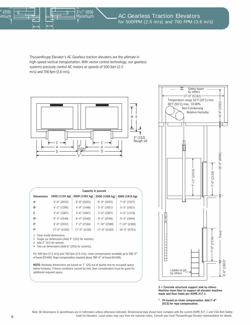
AC Gearless Traction Elevatorsfor 500FPM (2.5 m/s) and 700 FPM (3.6 m/s)
4" (102)Rough sill
AC
DF
B E
AC
D
4"(102)
ThyssenKrupp Elevator’s AC Gearless traction elevators are the ultimate in high-speed vertical transportation. With vector control technology, our gearless systems precisely control AC motors at speeds of 500 fpm (2.5 m/s) and 700 fpm (3.6 m/s).
1 Clear inside dimensions.2 Single car dimensions (Add 4” (102) for seismic).3 Add 2” (51) for seismic.4 Two car dimensions (Add 8” (203) for seismic).
For 500 fpm (2.5 m/s) and 700 fpm (3.6 m/s), chain compensation available up to 300’-0” of travel (91440). Rope compensation required above 300’-0” of travel (91440).
NOTE: Hoistway dimensions are based on 1” (25) out of plumb and no occupied space below hoistway. If these conditions cannot be met, then consideration must be given for additional required space.
A1
Dimensions 2500 (1135 kg) 3000 (1362 kg)
6’-8” (2032) 6’-8” (2032)
B1
C
D2
E3
Capacity in pounds
F4
6’-8” (2032) 7’-8” (2337)
3500 (1598 kg) 4000 (1816 kg)
4’-3” (1295) 5’-5” (1651)4’-9” (1448) 5’-5” (1651)
3’-6” (1067) 3’-6” (1067)3’-6” (1067) 4’-0” (1219)
8’-4” (2540) 8’-4” (2540)8’-4” (2540) 9’-4” (2845)
6’-8” (2032) 7’-10” (2388)7’-2” (2184) 7’-10” (2388)
17’-0” (5182) 17’-0” (5182)17’-0” (5182) 19’-0” (5791)
Trav
el
7'-0
" (2
134)
7'-0
" (2
134)
20'-
0" (
6096
)6'
-6"
(198
1)*
7'-1
1" (
2413
)
8'-6
" (2
591)
17'-0" (5182)
Safety beamby others
Ladder to pitby others
S
Temperature range 50˚F (28˚C) min.90˚F (50˚C) max. 10-90% Non-Condensing Relative Humidity
S = Concrete structural support slab by others. Machine room floor to support all elevator machine loads and floor loads per ASME A17.1.
* Pit based on chain compensation. Add 2’-8” (813) for rope compensation.
Traction_07_14_08.indd 6Traction_07_14_08.indd 6 7/21/08 4:57:21 PM7/21/08 4:57:21 PM

7Note: All dimensions in parentheses are in millimeters unless otherwise indicated. Dimensional data shown here complies with the current ASME A17.1 and CSA B44 Safety Code for Elevators. Local codes may vary from the national codes. Consult your local ThyssenKrupp Elevator representative for details.
AC Gearless Traction Elevators800 FPM (4.0 m/s) 1000 fpm (5.0 m/s) 1200 fpm (6.1 m/s)
1 Clear inside dimensions.2 Single car dimensions. When speed = 800 fpm (4.0 m/s) add 4” (102) for seismic). When speed = 1000 fpm (5.0 m/s) or 1200 fpm (6.1 m/s) add 2” (51) (3” (76) for seismic).3 Add 2” (51) for seismic. When speed = 1200 fpm (6.1 m/s) add 4” (102).4 Two car dimensions. When speed = 800 fpm (4.0 m/s) add 8” (203) for seismic. When speed = 1000 fpm (5.0 m/s) or 1200 fpm (6.1 m/s) add 4” (102) (6” (152) for seismic).
A1
Dimensions 3000 (1361 kg) 3500 (1588 kg)
6’-8” (2032) 7’-8” (2337)
B1
C
D2
E3
Capacity in pounds
F4
6’-8” (2032)
4000 (1814 kg)
4’-9” (1448) 5’-5” (1651)5’-5” (1651)
3’-6” (1067) 4’-0” (1219)3’-6” (1067)
8’-4” (2540) 9’-4” (2845)8’-4” (2540)
7’-2” (2184) 7’-10” (2388)7’-10” (2388)
17’-0” (5182) 19’-0” (5791)17’-0” (5182)
4" (102)Rough sill
AC
DF
B E
AC
D
4"(102)
AC Gearless elevators with standard design can travel up to 1200 fpm (6.1 m/s) and are ideal for high-rise buildings of all kinds. These elevators deliver an unbeatable combination of speed, dependability and performance. For special design for speeds up to 1600 fpm (8.1 m/s) contact your local ThyssenKrupp Elevator representative.
Rope compensation only.
NOTE: Hoistway dimensions are based on 1” (25) out of plumb and no occupied space below hoistway. If these conditions cannot be met, then consideration must be given for additional required space.
* Per ASME A17.1 rule 2.2.4.2 must have separate pit access door 10’-0” maximum from access door sill to the pit floor or 13’-9” maximum from access door sillto pit floor if there is not a building floor below the terminal floor.
Speed feet per minute (fpm)
P
Capacity in lbs.
3000 (1361 kg)
Minimum pit, overhead and machine room dimensions
Dimensions 800 (4.0m/s) 1000 (5.0m/s)
O
1200 (6.1m/s)
O
24’-5” (7442) 27’-2” (8280)
24’-8” (7518) 27’-2” (8280)
11’-6” (3505) * 22’-6” (6858)
11’-6” (3505) * 22’-6” (6858)
20’-0” (6096)
3500/4000(1588/1814 kg)
P
11’-4” (3454)
21’-8” (6604)
11’-4” (3454)
Trav
el
Safety beamby other
* Ladder to pitby others
18'-0" (5486)
9'-8
" (2
946)
7'-0
" (2
134)
OP
7'-1
1" (
2413
)
7'-0
" (2
134)
S
Temperature range 50˚F (28˚C) min.90˚F (50˚C) max. 10-90% Non-CondensingRelative Humidity
S = Concrete structural support slab by others. Machine room floor to support all elevator machine loads and floor loads per ASME A17.1.
Traction_07_14_08.indd 7Traction_07_14_08.indd 7 7/21/08 4:57:22 PM7/21/08 4:57:22 PM

8Note: All dimensions in parentheses are in millimeters unless otherwise indicated. Dimensional data shown here complies with the current ASME A17.1 and CSA B44 Safety
Code for Elevators. Local codes may vary from the national codes. Consult your local ThyssenKrupp Elevator representative for details.
Cab OptionsDesign Perfection
Standard Cab Design
As shown below, our standard cab includes laminated plastic walls, a suspended ceilingwith baked enamel frame, brushed stainless steel fronts with column type swing return and baked enamel doors. Our new Signa4™ signal fixtures are included as the standard in all TKE cabs.
Standard Designs Laminated Plastic (TKLP) Flat Steel Wall (TKS) (not shown)
Upgrade Designs Raised Applied Panels (TKAP)
Walls
Custom Veneer Applied Panel
Available Panel Finishes: Mahogany Red Oak Maple Cherry Walnut
Doors
Our standard door height is 7’-0” (2134), but doors can be constructed up to 9’-0” (2743). Baked enamel and plastic laminate doors include a kickplate to match fronts. Doors havea baked enamel finish from our standard selector; or, provide us a paint sample and we can mix a color to your specifications.
Center-opening doors are standard for the 2500, 3000, 3500 and 4000 poundcapacity SPF models.
Single-speed doors arestandard for 2100 pound capacity SPF models.
Two-speed doors are standard for 4500 and 5000 pound capacity SPF models. 4’-6” doors are also available.
Upgrade Designs
Stainless Steel #4 #8 5WL Bronze Finish #4 #8 Plastic laminate without binders Plastic laminate with binders
Binders frame your plastic laminate doors. Stainless Steel #4 #8 Bronze Finish #4 #8
Available Styles: Vertical Horizontal
Available Panel Finishes: Plastic Laminate Stainless Steel #4 #8 5WL Bronze Finish #4 #8
Available Reveal Finishes: Baked Enamel Stainless Steel #4 #8 Bronze Finish #4 #8
Fronts
Standard Design
Column TypeAvailable Finishes:
Stainless Steel #4 #8 5WL Bronze Finish #4 #8
Upgrade Designs
Wrap AroundAvailable Finishes:
Stainless Steel #4 #8 5WL Bronze Finish #4 #8
Full-Width Wrap AroundAvailable Finishes:
Stainless Steel #4 #8 5WL Bronze Finish #4 #8
Sills
Standard Design
Aluminum
Upgrade Designs
Bronze Finish Nickel Silver
For more architectural products selections, contact your ThyssenKrupp Elevator sales representative.
Traction_07_14_08.indd 8Traction_07_14_08.indd 8 7/21/08 4:57:22 PM7/21/08 4:57:22 PM

9Note: All dimensions in parentheses are in millimeters unless otherwise indicated. Dimensional data shown here complies with the current ASME A17.1 and CSA B44 Safety Code for Elevators. Local codes may vary from the national codes. Consult your local ThyssenKrupp Elevator representative for details.
Cab OptionsDesign Perfection
Continuous Bar Available sizes 1/4”(6) wide by:
2”(50) 4”(102) 6”(152) Stainless Steel #4 #8 Bronze Finish #4 #8
Handrails
Our handrails provide quality and durability with style and attractiveness.
CylindricalAvailable sizes:
1 1/2” (38) diameter 2” (50) diameter Stainless Steel #4 #8 Bronze Finish #4 #8
Ceilings
All of our suspended ceilings are mounted 7’-4” (2235) above the finished floor. Ceilings can be raised by extending the cab height.
Standard Design
Baked enamel suspended frame with white translucent light diffusers.Available Frame Finishes:
Stainless Steel #4 #8 Bronze Finish #4 #8
Upgrade Designs
Disc Light Available Panel and Frame Finishes:
Baked Enamel Stainless Steel #4 #8 Bronze Finish #4 #8
Incandescent Downlight Baked Enamel Stainless Steel #4 #8 5WL Bronze Finish #4 #8
Island Type Halogen Downlight (Wood Core) Plastic Laminate Stainless Steel #4 #8 5WL Bronze Finish #4 #8
Halogen Downlights Baked Enamel Stainless Steel #4 #8 5WL Bronze Finish #4 #8
Island Type Perimeter Lighting (Wood Core) Plastic Laminate Stainless Steel #4 #8 5WL Bronze Finish #4 #8
Standard Glassback Arrangements
Glassback cab options can be incorporated intoany standard cab type as a premium option.
Frame Finish: Baked Enamel Aluminum Stainless Steel Bronze
Full HeightGlass above and below handrail
Above HandrailModesty panel below handrail matches wall finish
Miscellaneous Upgrades
Extended Cab(Higher ceilings for transport of tall objects)
Protection pads for fronts and wallsFor more architectural products selections, contact your ThyssenKrupp Elevator sales representative.
Traction_07_14_08.indd 9Traction_07_14_08.indd 9 7/21/08 4:57:28 PM7/21/08 4:57:28 PM

10Note: All dimensions in parentheses are in millimeters unless otherwise indicated. Dimensional data shown here complies with the current ASME A17.1 and CSA B44 Safety
Code for Elevators. Local codes may vary from the national codes. Consult your local ThyssenKrupp Elevator representative for details.
Passenger Elevator DoorThyssenKrupp Entrance Details
Note: Front walls should be left out until entrances are set in place or leave a minimum rough opening that is 15” (381) wider and 15” (381) higher than frame opening of doorway.
Note: For openings over 8’-0” (2438) consult factory.
Note: These diagrams show wall thickness and construction detail required in order to supply a minimum 1 1/2 HR. Warnock Hersey Label on entrances. Contact your local ThyssenKrupp Elevator representative for additional details.
6 1/2"Min.
Doo
r
3/4"
1/2" Doorto Sill
1/4"Doorto Door
1/4" Doorto Frame
1 1/4" Door
FinishedSill Line
WallLine
"B" + 5"
10 7
/16"
Pock
et
2 3/4" Door
2"7'
- 0"
Fra
me
Ope
ning
Min
imum
Flo
or to
Flo
or =
Fra
me
Ope
ning
+ 1
'- 4
1/2
"
Doo
r
8"Po
cket
1/2" Doorto Sill
2 3/4" Door
"B" + 3 1/2"
1/4" Doorto Frame
3/4"
5"Min.
Doo
r
FinishedSill Line
Wall Line
7'-
0" F
ram
e O
peni
ng
Min
imum
Flo
or to
Flo
or =
Fra
me
Ope
ning
+ 1
'- 2
1/8
"
2"
Center-opening & Single-speed Doors Two-speed Doors
Detail 1 (typ.) Detail 1 (typ.)
AB
Center-opening Doors
Detail 1 (typ.) Detail 2 (typ.)
AB
Two-speed Doors
Right hand entrance shown. Left hand available where required.
Detail 1 (typ.) Detail 2 (typ.)
AB
Single-speed Doors
Detail 1 Detail 2
Varia
ble
2" (51) 2" (51)
Varia
ble
Masonry Construction
Detail 1 Detail 2
31/2" (89)Minimum
31/2" (89)Minimum
2" (51) 2" (51)
Drywall Construction
Center-opening& Single-speed Doors
Two-speed Doors
Sill Support Supplied by ThyssenKrupp ElevatorSingle-speed Doors A - Clear Opening B - Rough Opening
SPF 2100lb models (ft-in) 3’-0” 4’-3”
(mm) 914 1295
SPF 2500, 3000, 3500 (ft-in) 3’-6” 4’-9”
and 4000lb models (mm) 1067 1448
Center-Opening Doors
All 2500, 3000, and (ft-in) 3’-6” 4’-9”
3500lb models (mm) 1067 1448
4000lb models (ft-in) 4’-0” 5’-3”
(mm) 1219 1600
Standard Two Speed Doors
All 4500, 5000lb (ft-in) 4’-0” 5’-3”
and 50H models (mm) 1219 1600
Optional Two-Speed Doors (4’-6” Wide)
All 4500, 5000lb (ft-in) 4’-6” 5’-9”
and 50H models (mm) 1372 1753
Traction_07_14_08.indd 10Traction_07_14_08.indd 10 7/21/08 4:57:30 PM7/21/08 4:57:30 PM

11
Work By Others
The following preparatory work is required in order to properly install the elevator equipment. The cost of this work is not included in the elevator proposal, since it is a part of the building construction.
1. A plumb and legal hoistway, properly framed and enclosed and including a pit of proper depth, and a pit ladder for each elevator. Drains, lights, access doors, waterproofing and hoistway ventilation, as required.
2. Enclosed elevator equipment room with electrical work outlets, adequate lighting, and heating and ventilation sufficient to maintain the room at a temperature of 50°F minimum to 100°F maximum.
3. Adequate supports and foundations to carry the loads of all equipment, including supports for guide rail brackets.
4. Complete connections from the electric power mains to each controller, including necessary circuit breakers and fused mainline disconnect switches.
5. Electric power of the same characteristics as the permanent supply without charge for the construction, testing and adjusting.
6. Proper trenching and backfilling for any underground piping or conduit.
7. Divider beams for rail brackets support as required.
8. Cutting of walls, floor, etc. and removal of such obstructions as may be necessary for proper installation of the elevator.
9. Grouting of door sills, hoistway frames, and signal fixtures after installation of the elevator equipment.
10. All painting, except as otherwise specified.
11. Temporary enclosures, barricades, or other protection from open hoistways and elevator work area during the time the elevator is being installed.
12. Temporary elevator service prior to completion and acceptance of complete installation.
13. Smoke sensors as required in accordance with NFPA**#72E and ASME A17.1.***
14. All telephone wiring to machine room control panel, and installation of telephone instrument or other communication equipment in elevator cab with all connections to elevator traveling cable and in machine room.
15. A standby power source, including necessary transfer switches and auxiliary contact, where elevator operation from an alternate power supply is required.
16. Adequate storage facilities for elevator equipment prior to and during installation.
17. A means to automatically disconnect the main line power supply to the elevator prior to the application of water in the elevator machine room will be furnished by the electrical contractor. This means shall not be self-resetting.
18. Setting of anchors and sleeves.
*Refer to elevator layout drawings for details of each requirement.
**National Fire Protection Code
***Safety Code for Elevators and Escalators
Work Not Included in the Elevator Contract*
Traction_07_14_08.indd 11Traction_07_14_08.indd 11 7/21/08 4:57:31 PM7/21/08 4:57:31 PM

TKE
0066
v07
.08
25M
070
8 G
SI P
rinte
d in
U.S
.A.
version 07.08All illustrations and specifications are based on information in effect at time of publication approval. ThyssenKrupp Elevator reserves the right to change specifications or design and to discontinue items without prior notice or obligation.
Copyright © 2008ThyssenKrupp Elevator Corporation
ThyssenKrupp ElevatorP.O. Box 2177Memphis, TN 38101Tel: 877-230-0303 (Toll Free)
thyssenkruppelevator.com
Traction_07_14_08.indd 12Traction_07_14_08.indd 12 7/21/08 4:57:31 PM7/21/08 4:57:31 PM