Embed Size (px)
Citation preview

1www.equitone.co.uk
PLANNING & APPLICATION GUIDE
Uniclass EPIC
L532:P511 E411:X52CI/SfB
(43) Xi3
UK Edition Jan 2017
2
“The primary function of an external wall is to separate the interior from the exterior of a building, so that the environment inside can be modified and controlled to satisfy the needs of the occupants.”
3
Contents
Section 1 INTRODUCTION 7
Section 2 EQUITONE MATERIALS 15
Section 3 WORKING WITH EQUITONE 40
Section 4 INSTALLATION OF EQUITONE 48
Section 5 SUPPORTING FRAME DESIGN 64
Section 6 DESIGN CONSIDERATIONS 84
Section 7 SPECIAL APPLICATION & MAINTENANCE 101

44
5 5
6
7
AN INTRODUCTION TO THIS MANUAL
This Planning and Application Guide has been written to illustrate to the reader that designing, specifying and installing the EQUITONE range of fibre cement panels is straight forward provided some simple rules are followed.
For ease of use, this guide is divided into a number of chapters. These are structured firstly to look at the materials and how these are manufactured, then how to work with the materials and how to install them and finally, we will look at what happens behind the panels and what needs to be considered when designing the facade. We finish with some basic information on special applications and how to maintain the facade to ensure many years of trouble-free performance.
The information in this guide is comprehensive, but not exhaustive and the reader will find more information through our experienced and knowledgeable Technical Advisory Service Tel: 01283 722588.
Section 1INTRODUCTION
8
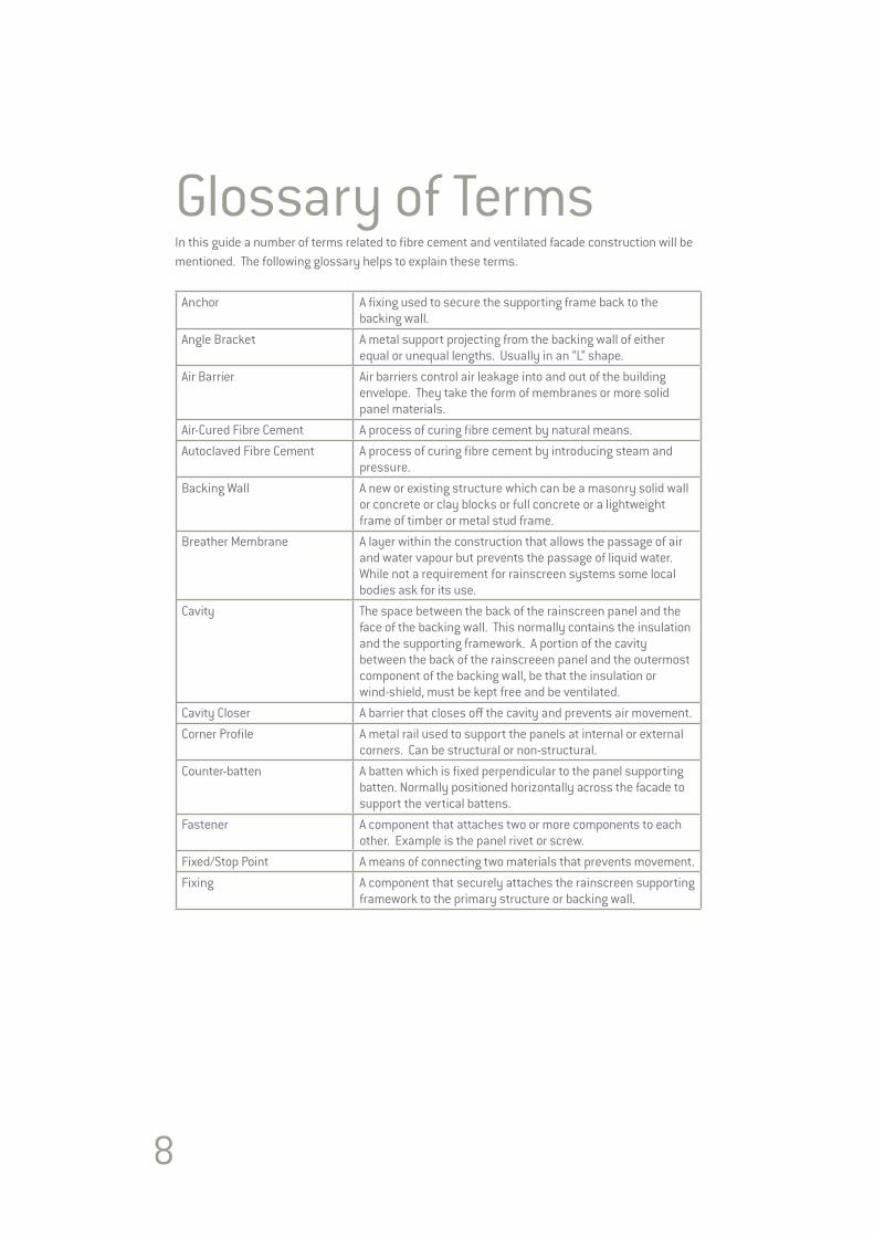
Glossary of Terms In this guide a number of terms related to fibre cement and ventilated facade construction will be mentioned. The following glossary helps to explain these terms.
Anchor A fixing used to secure the supporting frame back to the backing wall.
Angle Bracket A metal support projecting from the backing wall of either equal or unequal lengths. Usually in an “L” shape.
Air Barrier Air barriers control air leakage into and out of the building envelope. They take the form of membranes or more solid panel materials.
Air-Cured Fibre Cement A process of curing fibre cement by natural means.Autoclaved Fibre Cement A process of curing fibre cement by introducing steam and
pressure.Backing Wall A new or existing structure which can be a masonry solid wall
or concrete or clay blocks or full concrete or a lightweight frame of timber or metal stud frame.
Breather Membrane A layer within the construction that allows the passage of air and water vapour but prevents the passage of liquid water. While not a requirement for rainscreen systems some local bodies ask for its use.
Cavity The space between the back of the rainscreen panel and the face of the backing wall. This normally contains the insulation and the supporting framework. A portion of the cavity between the back of the rainscreeen panel and the outermost component of the backing wall, be that the insulation or wind-shield, must be kept free and be ventilated.
Cavity Closer A barrier that closes off the cavity and prevents air movement. Corner Profile A metal rail used to support the panels at internal or external
corners. Can be structural or non-structural.Counter-batten A batten which is fixed perpendicular to the panel supporting
batten. Normally positioned horizontally across the facade to support the vertical battens.
Fastener A component that attaches two or more components to each other. Example is the panel rivet or screw.
Fixed/Stop Point A means of connecting two materials that prevents movement.Fixing A component that securely attaches the rainscreen supporting
framework to the primary structure or backing wall.
9
Insulation Material with a low thermal conductivity usually placed within the cavity to reduce heat loss or heat gain through the wall. Many companies provide insulation materials designed specifically for ventilated facades.
L Profile A metal rail that is in an “L” shape used to support the panels normally behind the middle of the panel.
Omega Profile A metal rail that is a shape which is used to support the panels. Also referred to as a top-hat.
Perforated Profile A metal strip or angle piece which is perforated with holes, that is used at openings to prevent the entry of birds and vermin into the cavity space while permitting entry and exit of air.
Rainscreen Lightweight panel which deflects rainwater from the structure.Sliding/Go Point A means of connecting two materials that permits either or
both to move, expand or contract in response to different climate conditions.
Supporting Framework The framing support which supports the rainscreen panels, which may consist of a simple timber batten system, or more complex extruded or folded metal rails and angle brackets.
Thermostop A non-conducting material which acts as a barrier or isolator that is used to help reduce the transmittance of heat through components.
T Profile A metal rail that is in a “T” shape used to support the panels normally behind a vertical joint.
U Profile A metal rail that is in a “U” shape used to support the panels normally behind the middle of the panel.
Ventilated Facade or Rainscreen Cladding
A system of components assembled on the face of a building to form a multi-layered wall that provides a barrier to wind and rain, and meets other requirements. The main elements are the rainscreen panel, cavity insulation, and backing wall.
Vapour Barrier A layer within the construction intended to prevent the passage of water vapour through the wall. Normally positioned on the warm side of the insulation on the inner face of the wall.
Ventilation The passage of air into the cavity in order to dry residual water or evaporate moisture.
Vertical Profile A member that runs vertically to which the panel is fastened.Wall A wall comprises all the elements of the building envelope
from the outer layer, usually the rainscreen panel to the inner layer normally the dry lining or internal plaster.
Wind Shield A panel that is used on the outer side of a lightweight construction to provide a weatherproof barrier. Racking strength and fire resistance may also be a requirement.
10
wall structure
outer layer
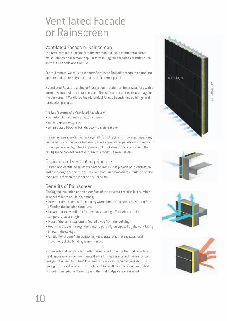
Ventilated Facade or RainscreenVentilated Facade or RainscreenThe term Ventilated Facade is more commonly used in continental Europe while Rainscreen is a more popular term in English speaking countries such as the UK, Canada and the USA.
For this manual we will use the term Ventilated Facade to mean the complete system and the term Rainscreen as the external panel.
A Ventilated Facade is a kind of 2 stage construction, an inner structure with a protective outer skin, the rainscreen . This skin protects the structure against the elements. A Ventilated Facade is ideal for use in both new buildings and renovation projects.
The key features of a Ventilated Facade are: • an outer skin of panels, the rainscreen, • an air gap or cavity, and • an insulated backing wall that controls air leakage.
The rainscreen shields the backing wall from direct rain. However, depending on the nature of the joints between panels some water penetration may occur. The air gap and airtight backing wall combine to limit this penetration. The cavity space can evaporate or drain this moisture away safely.
Drained and ventilated principle Drained and ventilated systems have openings that provide both ventilation and a drainage escape route. This combination allows air to circulate and dry the cavity between the inner and outer skins. Benefits of RainscreenPlacing the insulation on the outer face of the structure results in a numberof benefits for the building, notably:• In winter time it keeps the building warm and the cold air is prevented from
affecting the building structure. • In summer the ventilated facade has a cooling effect when outside
temperatures are high. • Most of the sun’s rays are reflected away from the building. • Heat that passes through the panel is partially dissipated by the ventilating
effect in the cavity. • An additional benefit in controlling temperature is that the structural
movement of the building is minimised.
In conventional construction with internal insulation the thermal layer has weak spots where the floor meets the wall. These are called thermal or cold bridges. This results in heat loss and can cause surface condensation. By having the insulation on the outer face of the wall it can be easily mounted without interruptions; therefore any thermal bridges are eliminated.
11
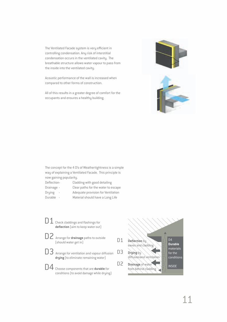
The Ventilated Facade system is very efficient in controlling condensation. Any risk of interstitial condensation occurs in the ventilated cavity. The breathable structure allows water vapour to pass from the inside into the ventilated cavity.
Acoustic performance of the wall is increased when compared to other forms of construction.
All of this results in a greater degree of comfort for the occupants and ensures a healthy building.
The concept for the 4 D’s of Weathertightness is a simple way of explaining a Ventilated Facade. This principle is now gaining popularity.Deflection- Cladding with good detailingDrainage - Clear paths for the water to escapeDrying - Adequate provision for VentilationDurable - Material should have a Long Life
D1 Check claddings and flashings for deflection (aim to keep water out)
D2 Arrange for drainage paths to outside (should water get in)
D3 Arrange for ventilation and vapour diffusion drying (to eliminate remaining water)
D4 Choose components that are durable for conditions (to avoid damage while drying)
D1 Deflection by eaves and cladding
D3 Drying by diffusionand ventilation
D2 Drainage of water from behind cladding
D4Durablematerialsfor the conditions
INSIDE
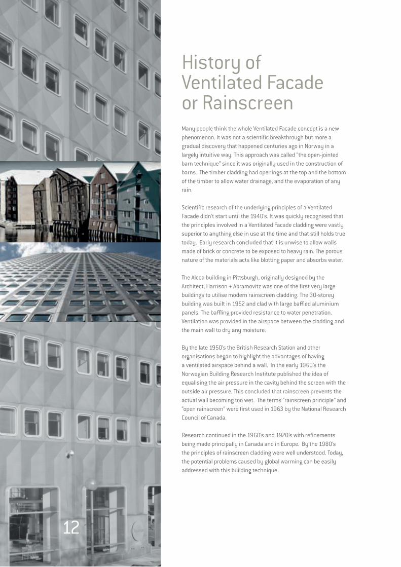
History of Ventilated Facade or RainscreenMany people think the whole Ventilated Facade concept is a new phenomenon. It was not a scientific breakthrough but more a gradual discovery that happened centuries ago in Norway in a largely intuitive way. This approach was called “the open-jointed barn technique” since it was originally used in the construction of barns. The timber cladding had openings at the top and the bottom of the timber to allow water drainage, and the evaporation of any rain.
Scientific research of the underlying principles of a Ventilated Facade didn’t start until the 1940’s. It was quickly recognised that the principles involved in a Ventilated Facade cladding were vastly superior to anything else in use at the time and that still holds true today. Early research concluded that it is unwise to allow walls made of brick or concrete to be exposed to heavy rain. The porous nature of the materials acts like blotting paper and absorbs water.
The Alcoa building in Pittsburgh, originally designed by the Architect, Harrison + Abramovitz was one of the first very large buildings to utilise modern rainscreen cladding. The 30-storey building was built in 1952 and clad with large baffled aluminium panels. The baffling provided resistance to water penetration. Ventilation was provided in the airspace between the cladding and the main wall to dry any moisture.
By the late 1950’s the British Research Station and other organisations began to highlight the advantages of having a ventilated airspace behind a wall. In the early 1960’s the Norwegian Building Research Institute published the idea of equalising the air pressure in the cavity behind the screen with the outside air pressure. This concluded that rainscreen prevents the actual wall becoming too wet. The terms “rainscreen principle” and “open rainscreen” were first used in 1963 by the National Research Council of Canada.
Research continued in the 1960’s and 1970’s with refinements being made principally in Canada and in Europe. By the 1980’s the principles of rainscreen cladding were well understood. Today, the potential problems caused by global warming can be easily addressed with this building technique.
12
13
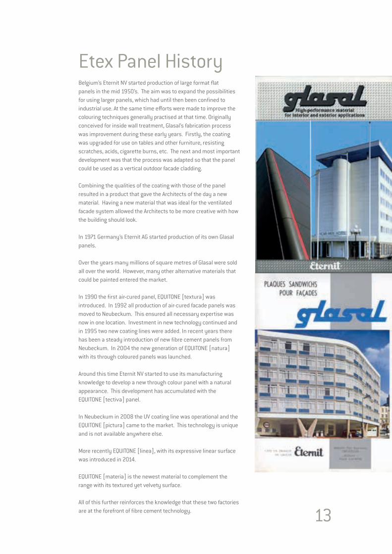
Etex Panel HistoryBelgium’s Eternit NV started production of large format flat panels in the mid 1950’s. The aim was to expand the possibilities for using larger panels, which had until then been confined to industrial use. At the same time efforts were made to improve the colouring techniques generally practised at that time. Originally conceived for inside wall treatment, Glasal’s fabrication process was improvement during these early years. Firstly, the coating was upgraded for use on tables and other furniture, resisting scratches, acids, cigarette burns, etc. The next and most important development was that the process was adapted so that the panel could be used as a vertical outdoor facade cladding.
Combining the qualities of the coating with those of the panel resulted in a product that gave the Architects of the day a new material. Having a new material that was ideal for the ventilated facade system allowed the Architects to be more creative with how the building should look.
In 1971 Germany’s Eternit AG started production of its own Glasal panels.
Over the years many millions of square metres of Glasal were sold all over the world. However, many other alternative materials that could be painted entered the market.
In 1990 the first air-cured panel, EQUITONE [textura] was introduced. In 1992 all production of air-cured facade panels was moved to Neubeckum. This ensured all necessary expertise was now in one location. Investment in new technology continued and in 1995 two new coating lines were added. In recent years there has been a steady introduction of new fibre cement panels from Neubeckum. In 2004 the new generation of EQUITONE [natura] with its through coloured panels was launched.
Around this time Eternit NV started to use its manufacturing knowledge to develop a new through colour panel with a natural appearance. This development has accumulated with the EQUITONE [tectiva] panel.
In Neubeckum in 2008 the UV coating line was operational and the EQUITONE [pictura] came to the market. This technology is unique and is not available anywhere else.
More recently EQUITONE [linea], with its expressive linear surface was introduced in 2014.
EQUITONE [materia] is the newest material to complement the range with its textured yet velvety surface.
All of this further reinforces the knowledge that these two factories are at the forefront of fibre cement technology.
14
15
EQUITONE MATERIALS
Section 2EQUITONE MATERIALS
16
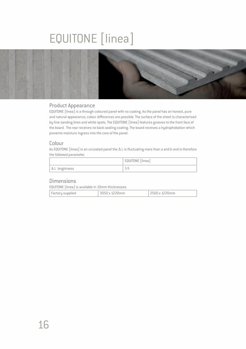
EQUITONE [linea]
Product AppearanceEQUITONE [linea] is a through coloured panel with no coating. As the panel has an honest, pure and natural appearance, colour differences are possible. The surface of the sheet is characterised by fine sanding lines and white spots. The EQUITONE [linea] features grooves to the front face of the board. The rear receives no back-sealing coating. The board receives a hydrophobation which prevents moisture ingress into the core of the panel.
ColourAs EQUITONE [linea] is an uncoated panel the Δ L is fluctuating more than a and b and is therefore the followed parameter.
EQUITONE [linea]
Δ L brightness 1-5
DimensionsEQUITONE [linea] is available in 10mm thicknesses.
Factory supplied 3050 x 1220mm 2500 x 1220mm

17
Technical PropertiesEQUITONE [linea] cladding boards conform to the requirements of EN 12467: 2012 “Fibre cement flat sheets – Product specification and test methods“. The results below are presented as defined by the standard.
Test Result according to ISO 9001 Quality Management System
Minimum Density Dry EN12467 1580 kg/m³Bending Strength Parallel Ambient EN12467 32.0 N/mm²Bending Strength Perpendicular Ambient EN12467 22.0 N/mm²Modulus of Elasticity Ambient EN12467 >14,000 N/mm²Hygric Movement 0-100% 1.6 mm/mWater Absorption of uncoated panel 0-100% < 25 %
Classification
Durability classification EN12467 Category AStrength classification EN12467 Class 5Fire Reaction EN13501-1 A2-s1, d0
Extra Tests
Water impermeability Test EN12467 PassWarm Water Test EN12467 PassSoak / Dry Test EN12467 Pass
Freeze Thaw Test for Category A Panel EN12467 PassHeat / Rain Test for Catagory A Panel EN12467 PassDimensional Tolerances for Level I Panel EN12467 PassThermal Movement 0.01 mm/mKThermal Conductivity 0.390 W/mK
Panel Weight (air-dried)
Panel Weight 2500 x 1220mm 3050 x 1220mm10mm 16.8 kg/m² 51.2 kg/panel 62.5 kg/panel
Tolerances in accordance with EN12467 Level I
Factory supplied± 1mm Thickness 10mm Panel± 2mm Length 10mm± 2mm Width 10mm1.0mm/m Squareness 10mm
The dimensions of the grooves are purely indicative. These are nominal dimensions subject to manufacturing tolerances. The grooves are longitudinal in the sheet.
18
EQUITONE [tectiva]
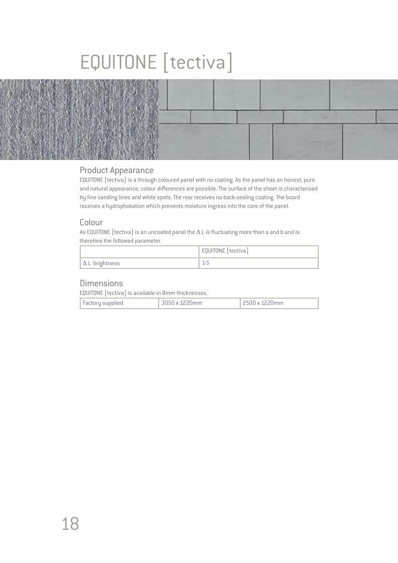
Product AppearanceEQUITONE [tectiva] is a through coloured panel with no coating. As the panel has an honest, pure and natural appearance, colour differences are possible. The surface of the sheet is characterised by fine sanding lines and white spots. The rear receives no back-sealing coating. The board receives a hydrophobation which prevents moisture ingress into the core of the panel.
ColourAs EQUITONE [tectiva] is an uncoated panel the Δ L is fluctuating more than a and b and is therefore the followed parameter.
EQUITONE [tectiva]
Δ L brightness 1-5
DimensionsEQUITONE [tectiva] is available in 8mm thicknesses.
Factory supplied 3050 x 1220mm 2500 x 1220mm

19
Technical PropertiesEQUITONE [tectiva] cladding boards conform to the requirements of EN 12467: 2012 “Fibre cement flat sheets – Product specification and test methods“. The results below are presented as defined by the standard.
Test Result according to ISO 9001 Quality Management System
Minimum Density Dry EN12467 1580 kg/m³Bending Strength Parallel Ambient EN12467 32.0 N/mm²Bending Strength Perpendicular Ambient EN12467 22.0 N/mm²Modulus of Elasticity Ambient EN12467 >14,000 N/mm²Hygric Movement 0-100% 1.6 mm/mWater Absorption of uncoated panel 0-100% < 25 %
Classification
Durability classification EN12467 Category AStrength classification EN12467 Class 5Fire Reaction EN13501-1 A2-s1, d0
Extra Tests
Water impermeability Test EN12467 PassWarm Water Test EN12467 PassSoak / Dry Test EN12467 Pass
Freeze Thaw Test for Category A Panel EN12467 PassHeat / Rain Test for Catagory A Panel EN12467 PassDimensional Tolerances for Level I Panel EN12467 PassThermal Movement 0.01 mm/mKThermal Conductivity 0.390 W/mK
Panel Weight (air-dried)
Panel Weight 2500 x 1220mm 3050 x 1220mm8mm 14.9 kg/m² 46.5 kg/panel 56.7 kg/panel
Tolerances in accordance with EN12467 Level I
Factory supplied± 0.5mm Thickness 8mm Panel± 3mm Length 8mm± 3mm Width 8mm1.0mm/m Squareness 8mm
20
EQUITONE [materia]
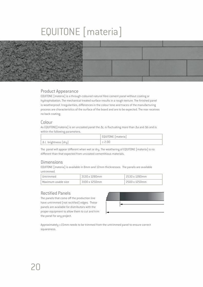
Product AppearanceEQUITONE [materia] is a through-coloured natural fibre cement panel without coating or hydrophobation. The mechanical treated surface results in a rough texture. The finished panel is weatherproof. Irregularities, differences in the colour tone and traces of the manufacturing process are characteristics of the surface of the board and are to be expected. The rear receives no back coating.
ColourAs EQUITONE[materia] is an uncoated panel the ΔL is fluctuating more than Δa and Δb and is within the following parameters.
EQUITONE [materia]
Δ L brightness (dry) ± 2.00
The panel will appear different when wet or dry. The weathering of EQUITONE [materia] is no different than that expected from uncoated cementitious materials.
DimensionsEQUITONE [materia] is available in 8mm and 12mm thicknesses. The panels are available untrimmed.
Untrimmed 3130 x 1280mm 2530 x 1280mm
Maximum usable size 3100 x 1250mm 2500 x 1250mm
Rectified PanelsThe panels that come off the production line have untrimmed (not rectified) edges. These panels are available for distributors with the proper equipment to allow them to cut and trim the panel for any project.
Approximately ±15mm needs to be trimmed from the untrimmed panel to ensure correct squareness.

21
Technical PropertiesEQUITONE [materia] cladding boards conform to the requirements of EN 12467:2012 “Fibre cement flat sheets – Product specification and test methods“. The results below are presented as defined by the standard.
Test Result according to ISO 9001 Quality Management System
Minimum Density Dry EN12467 1650 kg/m³Bending Strength Parallel Ambient EN12467 24.0 N/mm²Bending Strength Perpendicular Ambient EN12467 18.5 N/mm²Modulus of Elasticity Ambient EN12467 12,000 N/mm²Hygric Movement 30-95% 1.0 mm/mWater Absorption of uncoated panel 0-100% < 20 %Moisture Content Air-dried EN12467 < 8 %
Classification
Durability classification EN12467 Category A
Strength classification EN12467 Class 3
Fire Reaction EN13501-1 A2-s1, d0
Extra Tests
Water impermeability Test EN12467 PassWarm Water Test EN12467 PassSoak / Dry Test EN12467 PassFreeze Thaw Test for Category A Panel EN12467 PassHeat / Rain Test for Catagory A Panel EN12467 PassDimensional Tolerances for Level I Panel EN12467 PassThermal Movement 10.10-6 1/KThermal Conductivity 0.6 W/mK
Panel Weight (air-dried)
Panel Weight 2530 x 1280mm 3130 x 1280mm8mm 15.4 kg/m² 49.9 kg/panel 61.7 kg/panel12mm 22.8 kg/m² 73.8 kg/panel 91.4 kg/panel
22
EQUITONE [natura]
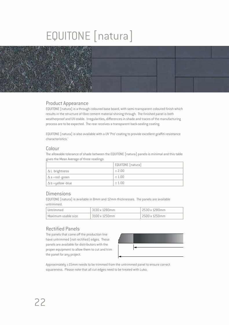
Product AppearanceEQUITONE [natura] is a through coloured base board, with semi-transparent coloured finish which results in the structure of fibre cement material shining through. The finished panel is both weatherproof and UV-stable. Irregularities, differences in shade and traces of the manufacturing process are to be expected. The rear receives a transparent back-sealing coating.
EQUITONE [natura] is also available with a UV ‘Pro’ coating to provide excellent graffiti resistance characteristics.’
ColourThe allowable tolerance of shade between the EQUITONE [natura] panels is minimal and this table gives the Mean Average of three readings.
EQUITONE [natura]
Δ L brightness ± 2.00
Δ a +red -green ± 1.00
Δ b +yellow -blue ± 1.00
DimensionsEQUITONE [natura] is available in 8mm and 12mm thicknesses. The panels are available untrimmed.
Untrimmed 3130 x 1280mm 2530 x 1280mm
Maximum usable size 3100 x 1250mm 2500 x 1250mm
Rectified PanelsThe panels that come off the production line have untrimmed (not rectified) edges. These panels are available for distributors with the proper equipment to allow them to cut and trim the panel for any project.
Approximately ±15mm needs to be trimmed from the untrimmed panel to ensure correct squareness. Please note that all cut edges need to be treated with Luko.
23
Technical PropertiesEQUITONE [natura] cladding boards conform to the requirements of EN 12467:2012 “Fibre cement flat sheets – Product specification and test methods“. The results below are presented as defined by the standard.
Test Result according to ISO 9001 Quality Management System
Minimum Density Dry EN12467 1650 kg/m³Bending Strength Parallel Ambient EN12467 24.0 N/mm²Bending Strength Perpendicular Ambient EN12467 17.0 N/mm²Modulus of Elasticity Ambient EN12467 15,000 N/mm²Hygric Movement 0-100% 1.0 mm/mWater Absorption of uncoated panel 0-100% < 20 %Moisture Content Air-dried EN12467 < 8 %
Classification
Durability classification EN12467 Category A
Strength classification EN12467 Class 4
Fire Reaction EN13501-1 A2-s1, d0
Extra Tests
Water impermeability Test EN12467 PassWarm Water Test EN12467 PassSoak / Dry Test EN12467 PassFreeze Thaw Test for Category A Panel EN12467 PassHeat / Rain Test for Catagory A Panel EN12467 PassDimensional Tolerances for Level I Panel EN12467 PassThermal Movement 0.01 mm/mKThermal Conductivity 0.6 W/mK
Panel Weight (air-dried)
Panel Weight 2530 x 1280mm 3130 x 1280mm8mm 15.4 kg/m² 49.9 kg/panel 61.7 kg/panel12mm 22.8 kg/m² 73.8 kg/panel 91.4 kg/panel
24
EQUITONE [pictura]
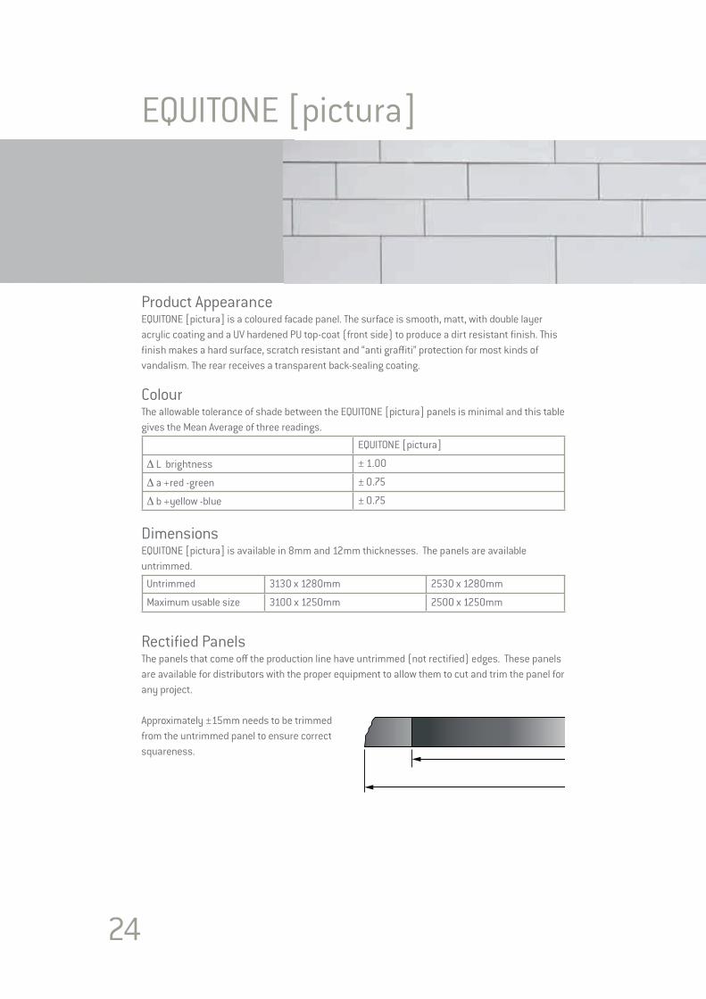
Product AppearanceEQUITONE [pictura] is a coloured facade panel. The surface is smooth, matt, with double layer acrylic coating and a UV hardened PU top-coat (front side) to produce a dirt resistant finish. This finish makes a hard surface, scratch resistant and “anti graffiti” protection for most kinds of vandalism. The rear receives a transparent back-sealing coating.
ColourThe allowable tolerance of shade between the EQUITONE [pictura] panels is minimal and this table gives the Mean Average of three readings.
EQUITONE [pictura]
Δ L brightness ± 1.00
Δ a +red -green ± 0.75
Δ b +yellow -blue ± 0.75
DimensionsEQUITONE [pictura] is available in 8mm and 12mm thicknesses. The panels are available untrimmed.
Untrimmed 3130 x 1280mm 2530 x 1280mm
Maximum usable size 3100 x 1250mm 2500 x 1250mm
Rectified PanelsThe panels that come off the production line have untrimmed (not rectified) edges. These panels are available for distributors with the proper equipment to allow them to cut and trim the panel for any project.
Approximately ±15mm needs to be trimmed from the untrimmed panel to ensure correct squareness.
25
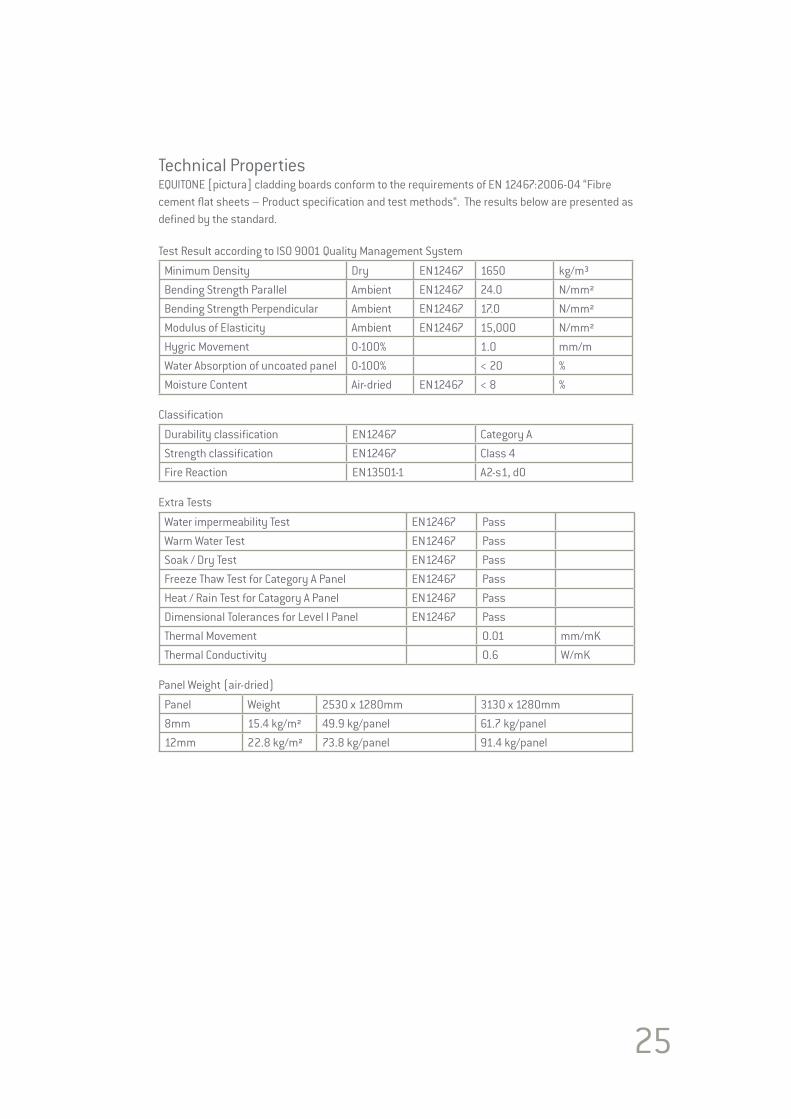
Technical PropertiesEQUITONE [pictura] cladding boards conform to the requirements of EN 12467:2006-04 “Fibre cement flat sheets – Product specification and test methods“. The results below are presented as defined by the standard.
Test Result according to ISO 9001 Quality Management System
Minimum Density Dry EN12467 1650 kg/m³Bending Strength Parallel Ambient EN12467 24.0 N/mm²Bending Strength Perpendicular Ambient EN12467 17.0 N/mm²Modulus of Elasticity Ambient EN12467 15,000 N/mm²Hygric Movement 0-100% 1.0 mm/mWater Absorption of uncoated panel 0-100% < 20 %Moisture Content Air-dried EN12467 < 8 %
Classification
Durability classification EN12467 Category AStrength classification EN12467 Class 4Fire Reaction EN13501-1 A2-s1, d0
Extra Tests
Water impermeability Test EN12467 PassWarm Water Test EN12467 PassSoak / Dry Test EN12467 PassFreeze Thaw Test for Category A Panel EN12467 PassHeat / Rain Test for Catagory A Panel EN12467 PassDimensional Tolerances for Level I Panel EN12467 PassThermal Movement 0.01 mm/mKThermal Conductivity 0.6 W/mK
Panel Weight (air-dried)
Panel Weight 2530 x 1280mm 3130 x 1280mm8mm 15.4 kg/m² 49.9 kg/panel 61.7 kg/panel12mm 22.8 kg/m² 73.8 kg/panel 91.4 kg/panel
26
EQUITONE [textura]
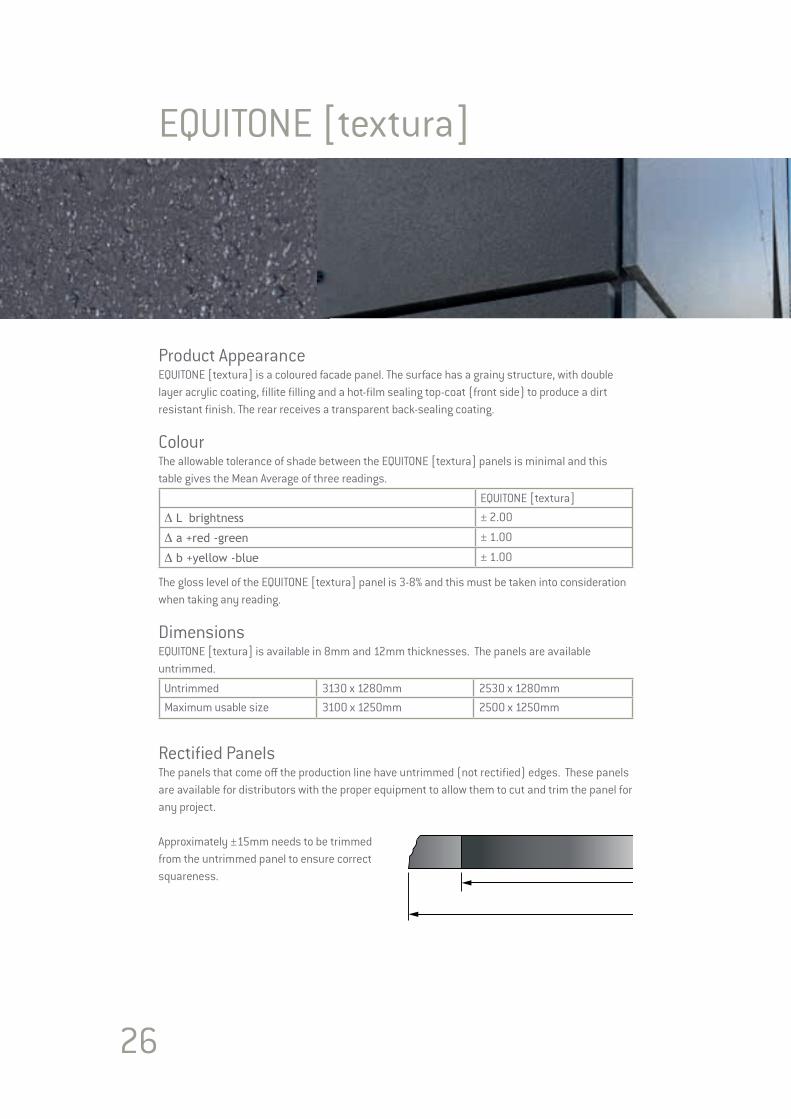
Product AppearanceEQUITONE [textura] is a coloured facade panel. The surface has a grainy structure, with double layer acrylic coating, fillite filling and a hot-film sealing top-coat (front side) to produce a dirt resistant finish. The rear receives a transparent back-sealing coating.
ColourThe allowable tolerance of shade between the EQUITONE [textura] panels is minimal and this table gives the Mean Average of three readings.
EQUITONE [textura]
Δ L brightness ± 2.00
Δ a +red -green ± 1.00
Δ b +yellow -blue ± 1.00
The gloss level of the EQUITONE [textura] panel is 3-8% and this must be taken into consideration when taking any reading.
DimensionsEQUITONE [textura] is available in 8mm and 12mm thicknesses. The panels are available untrimmed.
Untrimmed 3130 x 1280mm 2530 x 1280mmMaximum usable size 3100 x 1250mm 2500 x 1250mm
Rectified PanelsThe panels that come off the production line have untrimmed (not rectified) edges. These panels are available for distributors with the proper equipment to allow them to cut and trim the panel for any project.
Approximately ±15mm needs to be trimmed from the untrimmed panel to ensure correct squareness.
27
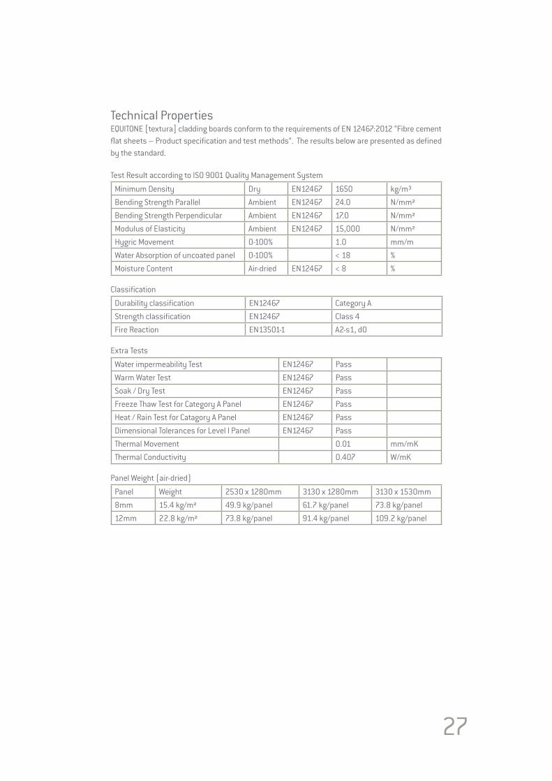
Technical PropertiesEQUITONE [textura] cladding boards conform to the requirements of EN 12467:2012 “Fibre cement flat sheets – Product specification and test methods“. The results below are presented as defined by the standard.
Test Result according to ISO 9001 Quality Management System
Minimum Density Dry EN12467 1650 kg/m³Bending Strength Parallel Ambient EN12467 24.0 N/mm²Bending Strength Perpendicular Ambient EN12467 17.0 N/mm²Modulus of Elasticity Ambient EN12467 15,000 N/mm²Hygric Movement 0-100% 1.0 mm/mWater Absorption of uncoated panel 0-100% < 18 %Moisture Content Air-dried EN12467 < 8 %
Classification
Durability classification EN12467 Category AStrength classification EN12467 Class 4Fire Reaction EN13501-1 A2-s1, d0
Extra Tests
Water impermeability Test EN12467 PassWarm Water Test EN12467 PassSoak / Dry Test EN12467 PassFreeze Thaw Test for Category A Panel EN12467 PassHeat / Rain Test for Catagory A Panel EN12467 PassDimensional Tolerances for Level I Panel EN12467 PassThermal Movement 0.01 mm/mKThermal Conductivity 0.407 W/mK
Panel Weight (air-dried)
Panel Weight 2530 x 1280mm 3130 x 1280mm 3130 x 1530mm8mm 15.4 kg/m² 49.9 kg/panel 61.7 kg/panel 73.8 kg/panel12mm 22.8 kg/m² 73.8 kg/panel 91.4 kg/panel 109.2 kg/panel

28
AccessoriesCentralising ToolThis accessory fits any standard drilling machine and is used with all EQUITONE panels which are to be fixed to a metal supporting frame.
The use of this tool guarantees that the smaller rivet hole in the vertical profile is centred in the larger panel hole. This guarantees the best allowance for support frame movement. The tool has a guide that neatly fits into the panel hole. The drill bit then extends to drill the profile. The drill bits can be easily replaced at the end of their life.
The centalising tool is available in a number of configurations to suit the panel and the rivet size and type.
It is recommended to remove any drilling debris from the hole before fixing.
Rivet Setting ToolThis accessory fits onto the end of the rivet fixing tool and is used with EQUITONE [natura], [pictura], [textura], [tectiva] and [materia]. This tool keeps the head of the rivet away from the panel by a set distance. This prevents damage to the surface of the panel by over fixing the UNI-rivet.
The rivet setting tool is available to suit both the standard aluminium and stainless steel UNI-rivets.
Foam TapeThis tape is used when fixing all EQUITONE boards to metal support frames. The tape comes with a self-adhesive strip. When conditions are unfavourable, such as very cold or wet weather, it is advisable to either apply the tape onto the profiles indoors and then fix the profiles, or alternatively, warm/dry the profiles.
Drill BitsThese are specially designed fibre cement drill bits for drilling the holes in the panels. This drill bit is a fully hardened steel bit with a cutting edge to suit fibre cement. This drill bit reduces risk of sliding on the panel surface, provides a clean cut with no burrs and does not cause burning. This results in a drill bit with a very long life.
The drill bit is available in diameters to suit the required hole size, 7mm or 11mm.

29
Routing tool – for EQUITONE [linea]For technical reasons the fasteners have to be aligned with the deeper part of the grooved surface. Therefore the ribs at the location of the fasteners have to be milled first. To mill the ribs a special tool is used. The tool is equipped with a drill in order to drive and mill the hole in one movement. The milling tool comes in different versions depending on the drill diameter.
EQUITONE saw bladesThese blades have been designed specially for fibre cement and when correctly used result in a high level of finish.
LukoLuko is a translucent liquid that is applied to the cut edges of EQUITONE [natura]. This reduces the risk of temporary damp staining to the panels edges. Luko is available in 0.5L container. The liquid should be used within 3 months of supply.Each container will treat approximately 325 linear metres.
Apply the Luko between temperatures +5° to +25°.
Never mix used Luko with new Luko. Please refer to page 45 for Luko guidelines.
Corner Profiles Corner profiles are available both as structural elements and non-structural elements. The structural versions play a role in supporting the panel and resisting the loads and are normally part of the supporting frame offering. The non-structural versions are decorative and specialised companies provide many options. These can be anodised or powder coated aluminium, galvanised steel or plastic.
The maximum thickness permitted for any of these non-structural profiles is 0.8mm. This will prevent any distortion of the panel. The profiles should be butt joints and should never overlap. Should thicker corner profiles be used then the corner support frame profile needs to be set back to accommodate this.
The corner profiles can be held in place via the panel fixing. However if this is not possible then the profile can be fixed independently. Any such fixing must be flush with the profile and not cause the panel to distort.
The joints between all corner profiles must coincide with those between the supporting frame profiles.
Any corner profile must not be fixed to two vertical support frames across the expansion gaps. To fix the profile across this gap will result in damage to the profile and the panels.
1 2 3
1 2 3
1 2 3
1 2 3
1 2 3
1 2 3
30
Horizontal Joint Profiles*To baffle the horizontal joint, an aluminium joint profile is inserted behind the panels. These are non-structural and different options are available. These can be anodised or powder coated aluminium, or plastic.
The maximum thickness permitted for any of these profiles is 0.8mm. This will prevent any distortion of the panel.
The horizontal joint profile is clamped between the panel and the supporting frame. Aesthetically, it is best not to continue the profile across the vertical joints but to cut it leaving the profile 2mm shorter at each side.
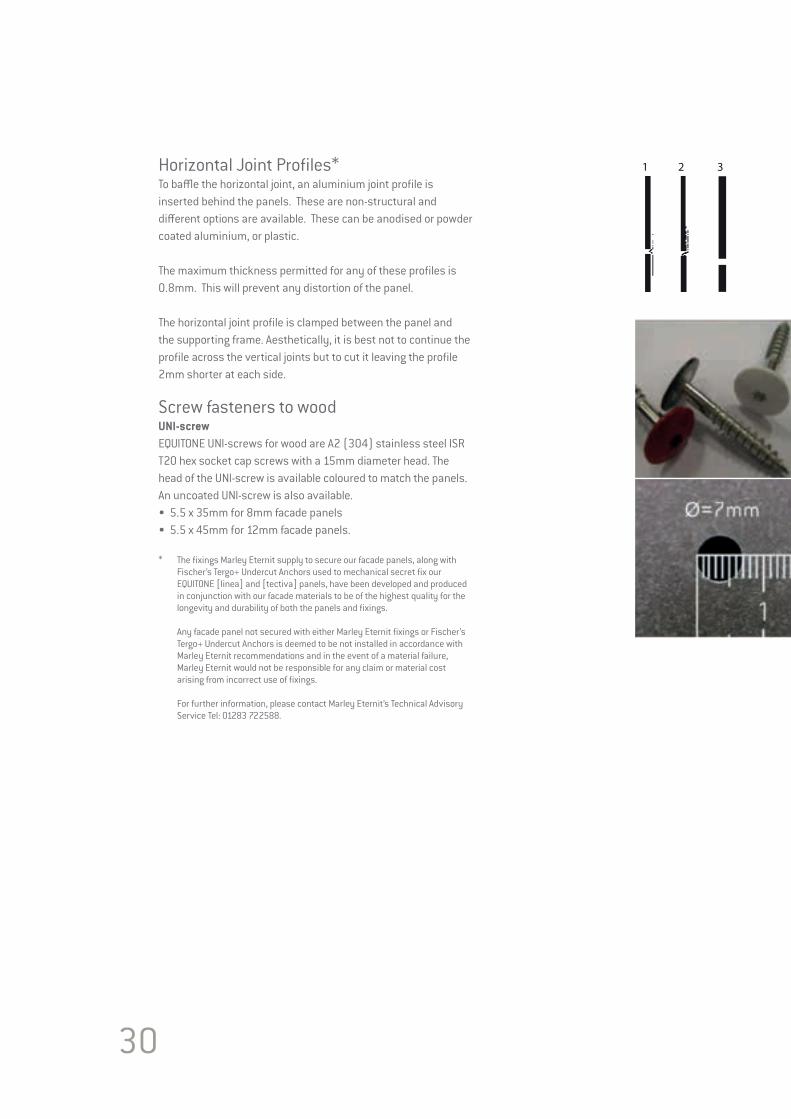
Screw fasteners to woodUNI-screwEQUITONE UNI-screws for wood are A2 (304) stainless steel ISR T20 hex socket cap screws with a 15mm diameter head. The head of the UNI-screw is available coloured to match the panels. An uncoated UNI-screw is also available.• 5.5 x 35mm for 8mm facade panels • 5.5 x 45mm for 12mm facade panels.
* The fixings Marley Eternit supply to secure our facade panels, along with Fischer’s Tergo+ Undercut Anchors used to mechanical secret fix our EQUITONE [linea] and [tectiva] panels, have been developed and produced in conjunction with our facade materials to be of the highest quality for the longevity and durability of both the panels and fixings.
Any facade panel not secured with either Marley Eternit fixings or Fischer’s Tergo+ Undercut Anchors is deemed to be not installed in accordance with Marley Eternit recommendations and in the event of a material failure, Marley Eternit would not be responsible for any claim or material cost arising from incorrect use of fixings.
For further information, please contact Marley Eternit’s Technical Advisory Service Tel: 01283 722588.
1 2 3
1 2 3

Hole PositionThe position of the holes is as follows:• From the horizontal edges of the panel the dimension is 70mm -> 100mm. • From the side edges of the panel the dimension is 25mm ->100mm,
Placing the corner screws 80mm from the horizontal edge 25mm from the vertical edges visually is the preferred location.
Centres for the rest of the fixings are determined based on the engineers wind load calculations.
This all ensures that the panel is accurately fixed into position while making certain that the panel is stress-free.
Screw collar for EQUITONE [pictura] and [natura] with Pro coating* The screw collar should be inserted into all holes before screw fixing. This collar offers extra protection to the Pro top coating to prevent peeling.
* The fixings Marley Eternit supply to secure our facade panels, along with Fischer’s Tergo+ Undercut Anchors used to mechanical secret fix our EQUITONE [linea] and [tectiva] panels, have been developed and produced in conjunction with our facade materials to be of the highest quality for the longevity and durability of both the panels and fixings.
Any facade panel not secured with either Marley Eternit fixings or Fischer’s Tergo+ Undercut Anchors is deemed to be not installed in accordance with Marley Eternit recommendations and in the event of a material failure, Marley Eternit would not be responsible for any claim or material cost arising from incorrect use of fixings.
For further information, please contact Marley Eternit’s Technical Advisory Service Tel: 01283 722588.
31

32
Rivet fixingEQUITONE may be face fixed to metal supporting frame using the EQUITONE UNI-rivet. The rivets have colour matched heads to blend in with the panel. Aluminium rivets can only be used with aluminium supporting frame. Stainless steel rivets can be used with, aluminium, galvanised or stainless steel supporting frames.
Rivet FastenersEQUITONE UNI-rivet is available as:• 4x18 K15 AlMg5 Aluminium rivet for 8mm panel• 4x25 K15 AlMg5 Aluminium rivet for 12mm panel and extra thick support frame• 4x18 K15 A2 (304) Stainless Steel rivet for 8mm panel• 4x22 K15 A2 (304) Stainless Steel rivet for 12mm panel
Other lengths of rivets are available.
ProcedureThe procedure for fixing all EQUITONE panels is the same. The panel must be pre drilled with an 11mm diameter size hole to allow for rivet fixing.
Each panel has two Fixed/Stop points. The two Fixed/Stop points are formed by using the red rivet sleeves to fill the oversized hole. No red sleeve is used for the Sliding/Go holes. A centralising tool is used to drive the rivet hole in the supporting frame. A rivet setting tool which fits to the end of the rivet gun can be used to prevent scratching the rivet head and ensure the correct placement of the UNI-rivet.
Hole PositionThe position of the holes is as follows.• From the horizontal edges of the panel the dimension is 70mm -> 100mm.• From the side edges of the panel the dimension is 30mm -> 100mm.
Placing the corner UNI-rivets 80mm from the horizontal edge 30mm from the vertical edges visually is the preferred location.
The centres for the rest of the fixings are determined based on the engineers wind load calculations.
Important Note: Aluminium UNI-rivets must not be used with galvanised profiles due to the risk of bi-metallic corrosion. This all ensures that the panel is accurately fixed into position while making certain that the panel is stress free.
100mm
70mm
100mm 30mm
Corner rivet
80mm
30mm
EQUITONE UNI-rivet
EQUITONE UNI-rivet RED STOP point sleeve
33
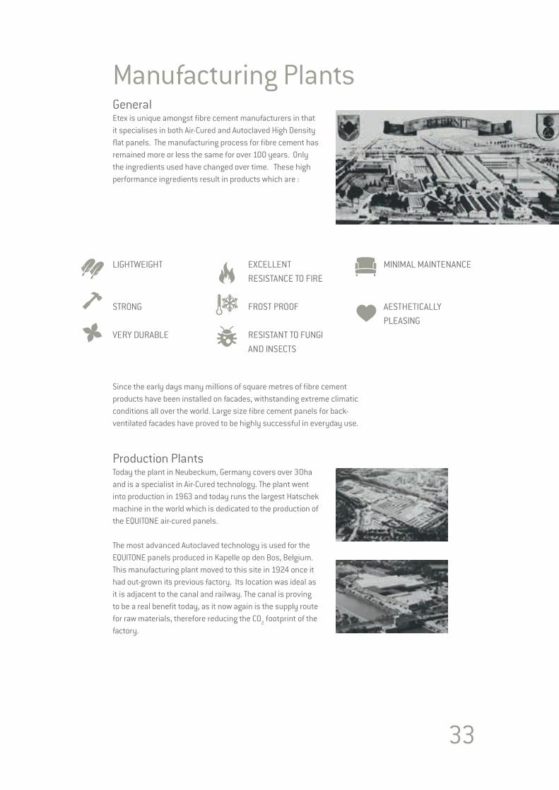
Manufacturing Plants GeneralEtex is unique amongst fibre cement manufacturers in that it specialises in both Air-Cured and Autoclaved High Density flat panels. The manufacturing process for fibre cement has remained more or less the same for over 100 years. Only the ingredients used have changed over time. These high performance ingredients result in products which are :
Since the early days many millions of square metres of fibre cement products have been installed on facades, withstanding extreme climatic conditions all over the world. Large size fibre cement panels for back-ventilated facades have proved to be highly successful in everyday use.
Production PlantsToday the plant in Neubeckum, Germany covers over 30ha and is a specialist in Air-Cured technology. The plant went into production in 1963 and today runs the largest Hatschek machine in the world which is dedicated to the production of the EQUITONE air-cured panels.
The most advanced Autoclaved technology is used for the EQUITONE panels produced in Kapelle op den Bos, Belgium. This manufacturing plant moved to this site in 1924 once it had out-grown its previous factory. Its location was ideal as it is adjacent to the canal and railway. The canal is proving to be a real benefit today, as it now again is the supply route for raw materials, therefore reducing the CO2 footprint of the factory.
LIGHTWEIGHT
STRONG VERY DURABLE
EXCELLENT RESISTANCE TO FIRE
FROST PROOF RESISTANT TO FUNGI AND INSECTS
MINIMAL MAINTENANCE
AESTHETICALLY PLEASING

34
Standards & Certificates Both manufacturing facilities hold the latest versions of the following ISO certificatesISO 9001 Quality Management SystemISO 14001 Environmental Management SystemOHSAS 18001 Safety Management System
All EQUITONE panels are manufactured in accordance with the requirements of EN12467 “Fibre-cement flat sheets. Product specification and test methods.”
This standard sets out the requirements that all fibre cement panels should meet. In addition to this all EQUITONE panels are labelled with CE Marking in accordance with this standard. This further ensures that the products conform to the highest standards.
The CE marking is the sole evidence of conformity required by law. The CE marking displays the following information• The CE marking symbol• Details of the manufacturer (address) and manufacture (year)• Coded information on certain product properties• Declaration of conformity by the manufacturer
The CE marking is a kind of “technical passport”. Products bearing the CE marking can be traded within the European Union market. The manufacturer is responsible for affixing the CE marking.
In addition to the manufacturing certificates and European approvals, local approvals are also needed for some countries. Examples are; Irish Agrément Board, British Agrément Board, Avis Technique from France, Zulassung from Germany, ATG from Belgium, KOMO from Netherlands. Many of these approvals are acceptable in other countries.
To keep up to date with the latest issues and to promote ventilated facades, some of our Sales Organisations are also active members of their local institutes, such as the FHVF in Germany, CWCT in UK or the CSTB in France.
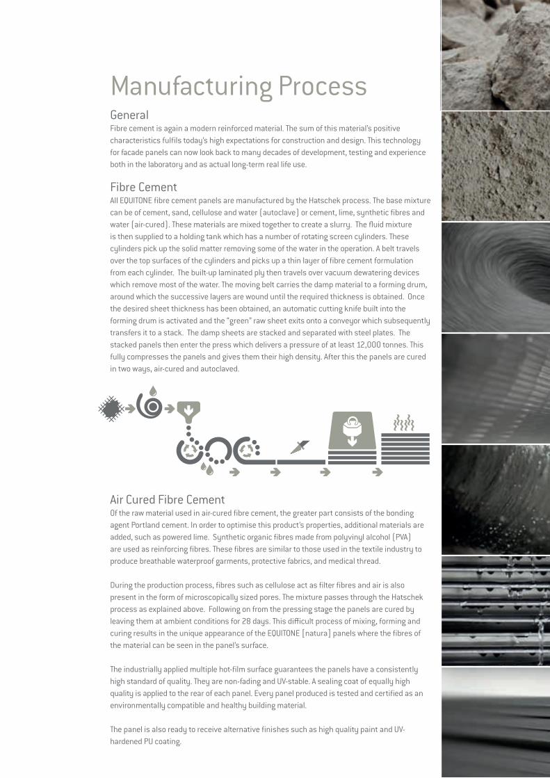
Manufacturing ProcessGeneralFibre cement is again a modern reinforced material. The sum of this material’s positive characteristics fulfils today’s high expectations for construction and design. This technology for facade panels can now look back to many decades of development, testing and experience both in the laboratory and as actual long-term real life use.
Fibre CementAll EQUITONE fibre cement panels are manufactured by the Hatschek process. The base mixture can be of cement, sand, cellulose and water (autoclave) or cement, lime, synthetic fibres and water (air-cured). These materials are mixed together to create a slurry. The fluid mixture is then supplied to a holding tank which has a number of rotating screen cylinders. These cylinders pick up the solid matter removing some of the water in the operation. A belt travels over the top surfaces of the cylinders and picks up a thin layer of fibre cement formulation from each cylinder. The built-up laminated ply then travels over vacuum dewatering devices which remove most of the water. The moving belt carries the damp material to a forming drum, around which the successive layers are wound until the required thickness is obtained. Once the desired sheet thickness has been obtained, an automatic cutting knife built into the forming drum is activated and the “green” raw sheet exits onto a conveyor which subsequently transfers it to a stack. The damp sheets are stacked and separated with steel plates. The stacked panels then enter the press which delivers a pressure of at least 12,000 tonnes. This fully compresses the panels and gives them their high density. After this the panels are cured in two ways, air-cured and autoclaved.
Air Cured Fibre CementOf the raw material used in air-cured fibre cement, the greater part consists of the bonding agent Portland cement. In order to optimise this product’s properties, additional materials are added, such as powered lime. Synthetic organic fibres made from polyvinyl alcohol (PVA) are used as reinforcing fibres. These fibres are similar to those used in the textile industry to produce breathable waterproof garments, protective fabrics, and medical thread.
During the production process, fibres such as cellulose act as filter fibres and air is also present in the form of microscopically sized pores. The mixture passes through the Hatschek process as explained above. Following on from the pressing stage the panels are cured by leaving them at ambient conditions for 28 days. This difficult process of mixing, forming and curing results in the unique appearance of the EQUITONE [natura] panels where the fibres of the material can be seen in the panel’s surface.
The industrially applied multiple hot-film surface guarantees the panels have a consistently high standard of quality. They are non-fading and UV-stable. A sealing coat of equally high quality is applied to the rear of each panel. Every panel produced is tested and certified as an environmentally compatible and healthy building material.
The panel is also ready to receive alternative finishes such as high quality paint and UV-hardened PU coating.
36
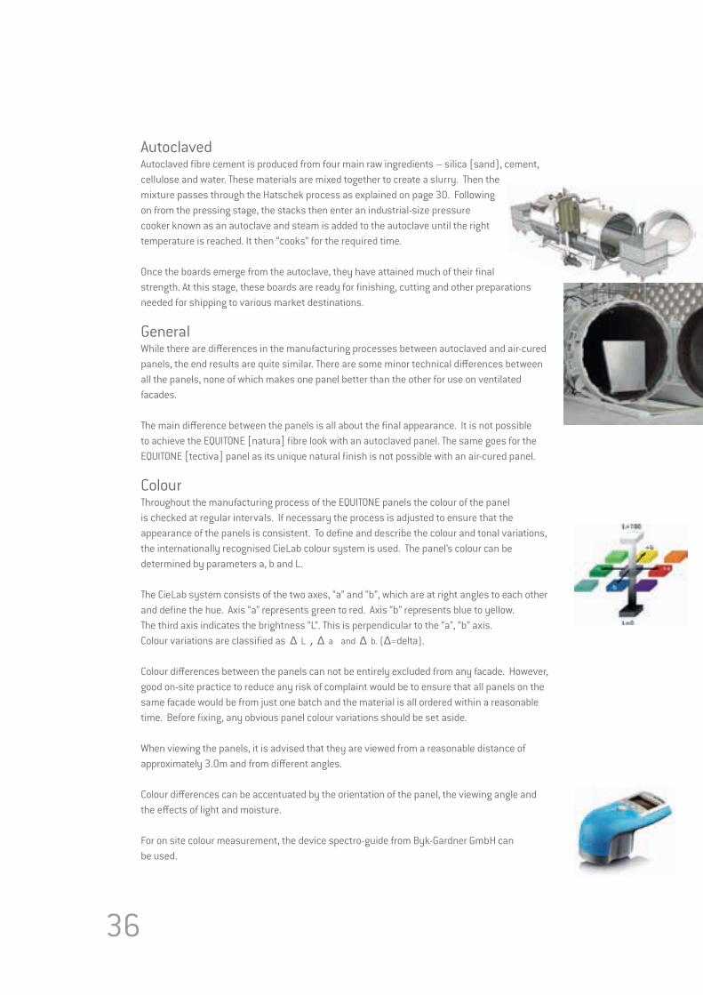
AutoclavedAutoclaved fibre cement is produced from four main raw ingredients – silica (sand), cement, cellulose and water. These materials are mixed together to create a slurry. Then the mixture passes through the Hatschek process as explained on page 30. Following on from the pressing stage, the stacks then enter an industrial-size pressure cooker known as an autoclave and steam is added to the autoclave until the right temperature is reached. It then “cooks” for the required time.
Once the boards emerge from the autoclave, they have attained much of their final strength. At this stage, these boards are ready for finishing, cutting and other preparations needed for shipping to various market destinations.
GeneralWhile there are differences in the manufacturing processes between autoclaved and air-cured panels, the end results are quite similar. There are some minor technical differences between all the panels, none of which makes one panel better than the other for use on ventilated facades.
The main difference between the panels is all about the final appearance. It is not possible to achieve the EQUITONE [natura] fibre look with an autoclaved panel. The same goes for the EQUITONE [tectiva] panel as its unique natural finish is not possible with an air-cured panel.
ColourThroughout the manufacturing process of the EQUITONE panels the colour of the panel is checked at regular intervals. If necessary the process is adjusted to ensure that the appearance of the panels is consistent. To define and describe the colour and tonal variations, the internationally recognised CieLab colour system is used. The panel’s colour can be determined by parameters a, b and L.
The CieLab system consists of the two axes, “a” and “b”, which are at right angles to each other and define the hue. Axis “a” represents green to red. Axis “b” represents blue to yellow.The third axis indicates the brightness “L”. This is perpendicular to the “a”, “b” axis.Colour variations are classified as Δ L , Δ a and Δ b. (Δ=delta).
Colour differences between the panels can not be entirely excluded from any facade. However, good on-site practice to reduce any risk of complaint would be to ensure that all panels on the same facade would be from just one batch and the material is all ordered within a reasonable time. Before fixing, any obvious panel colour variations should be set aside.
When viewing the panels, it is advised that they are viewed from a reasonable distance of approximately 3.0m and from different angles.
Colour differences can be accentuated by the orientation of the panel, the viewing angle and the effects of light and moisture.
For on site colour measurement, the device spectro-guide from Byk-Gardner GmbH can be used.

37
SustainabilityManufacturing PlantsEach of the manufacturing plants are continuously working to make the process more environmentally sustainable. Some recent initiatives include the switch from heavy fuel to natural gas, sourcing lime and sand locally, using cellulose from fully renewable sources, changing the way raw materials are delivered, for example transport via the canal, introducing a new co-generation power unit which recovers the primary energy and reuses it and aiming to have all hard factory waste recyclable. Both manufacturing plants operate in accordance with ISO 14001 Environmental Management System.
Energy Performance of BuildingsCommonly referred to as the 2020 directive, in December 2002, the European Parliament adopted directive 2002/91/EC on the energy performance of buildings. Clear energy-saving requirements for buildings are formulated in this directive. From 2020 onwards, all new buildings must be ‘nearly zero-energy’, by means of high energy-efficiency standards. This will involve the installation of improved insulation and consuming energy from renewable sources. Buildings occupied and owned by public authorities are expected to lead by example, so the provisions of this directive should apply to the public sector from 2018 onwards.
Green Building AssessmentsWhile this area of having a building assessed for its energy and environmental design is still in its infancy, it is growing and slowly becoming more popular. The goals of these schemes is to establish standards of measurement, promote good design practices, and recognize environmental leadership in building industry and to increase the awareness among customers by specifying the benefits of green building.
In Europe the predominant Green Building Scheme is BREEAM from the British Research Establishment, others include DGNB in Germany or HQE from France. Another, internationally-recognised green building certification system is the LEED, Leadership in Energy and Environmental Design from the U.S. Green Building Council. These all promote sustainable building and development practices through a suite of rating systems.
The BRE’s Environmental Assessment Method (BREEAM) is a design and management stage assessment tool that provides an environmental label for buildings, based on good practice. One of the aims of BREEAM and the other schemes are to encourage the use of materials that have lower impact on the environment, taking account of the full life cycle of the materials in question.
This is a complex part of the industry and is changing regularly. It is a minefield of competing commercial interests. The assessment itself is a very complex area and experts are becoming more common especially with “signature” buildings.There are different building ratings between each scheme. Therefore, it is not possible to rate one scheme against another as they all use information differently. They also give a different loading to the main elements of the scheme. For example, the materials section presents 22% in the DGNB, 13% in BREEAM and 14% in LEED.
38
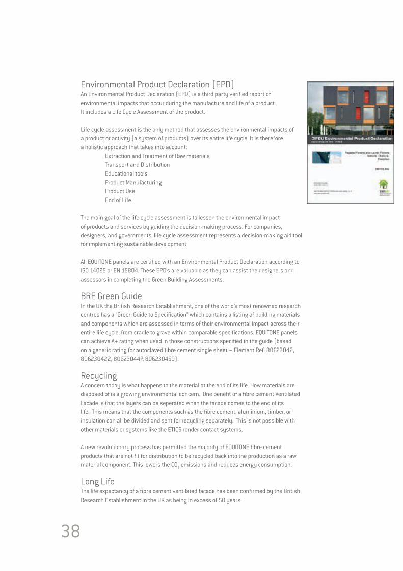
Environmental Product Declaration (EPD)An Environmental Product Declaration (EPD) is a third party verified report of environmental impacts that occur during the manufacture and life of a product. It includes a Life Cycle Assessment of the product.
Life cycle assessment is the only method that assesses the environmental impacts of a product or activity (a system of products) over its entire life cycle. It is therefore a holistic approach that takes into account: Extraction and Treatment of Raw materials Transport and Distribution Educational tools Product Manufacturing Product Use End of Life
The main goal of the life cycle assessment is to lessen the environmental impact of products and services by guiding the decision-making process. For companies, designers, and governments, life cycle assessment represents a decision-making aid tool for implementing sustainable development.
All EQUITONE panels are certified with an Environmental Product Declaration according to ISO 14025 or EN 15804. These EPD’s are valuable as they can assist the designers and assessors in completing the Green Building Assessments.
BRE Green GuideIn the UK the British Research Establishment, one of the world’s most renowned research centres has a “Green Guide to Specification” which contains a listing of building materials and components which are assessed in terms of their environmental impact across their entire life cycle, from cradle to grave within comparable specifications. EQUITONE panels can achieve A+ rating when used in those constructions specified in the guide (based on a generic rating for autoclaved fibre cement single sheet – Element Ref: 80623042, 806230422, 806230447, 806230450).
RecyclingA concern today is what happens to the material at the end of its life. How materials are disposed of is a growing environmental concern. One benefit of a fibre cement Ventilated Facade is that the layers can be seperated when the facade comes to the end of its life. This means that the components such as the fibre cement, aluminium, timber, or insulation can all be divided and sent for recycling separately. This is not possible with other materials or systems like the ETICS render contact systems.
A new revolutionary process has permitted the majority of EQUITONE fibre cement products that are not fit for distribution to be recycled back into the production as a raw material component. This lowers the CO2 emissions and reduces energy consumption.
Long LifeThe life expectancy of a fibre cement ventilated facade has been confirmed by the British Research Establishment in the UK as being in excess of 50 years.
39

40
WORKING WITH EQUITONE Section 3
WORKING WITH EQUITONE

41
ToolsFor a trouble free installation of EQUITONE, the following tools are advised. We promote the use of dust free tools for drilling and cutting the panels.
• Portable saws with a vacuum system and guide rail such as Festo AXT50LA or Mafell PS3100SE• EQUITONE Fibre Cement blades• Jigsaw with a Bosch T141HM blade • Angle grinders must not be used.• Cordless drill• EQUITONE Centralising Tool• EQUITONE Fibre Cement drill bits• Cordless Rivet gun - for example a Geispa Accubird• EQUITONE UNI-rivet Setting tool• Clamps which do not damage the panel surface• Spacers to set the gap at the joints• Suction Handle to lift panel into place• Metal support rail to assist during installation• Milling Tool
Site WorkHealth & SafetyAll EQUITONE panels have their own Material Safety Data Sheets which are complied in accordance with 1907/2006/EG article 31. These MSDS outline any hazards associated with working with the panels and measures to minimise the risk.
StorageAll panel materials must be stored flat on pallets, inside and undercover in dry conditions, protected from weather and other trades. Stack the pallets in a way so that the panels are ventilated. If moisture is allowed to penetrate between the stored sheets, permanent surface staining in the form of efflorescence may occur. Condensation within the packaging can be an issue when the conditions are warm. The outer plastic protection may cause condensation if it is not ventilated.
Do not deliver any panels to site which cannot be installed immediately or unloaded into a suitable well protected storage area. Store products clear of the ground and on level bearers at a maximum of 600mm centres. Individual stacks can be 500mm high, and not more than 5 stacks can be put on top of one another.
EQUITONE [natura], [pictura] and [textura] panels are supplied with protective paper or foil between the decorated faces. This protection should not be removed. Stack the panel’s front face-to-front face or rear surface-to-rear surface. The panels should not be placed face-to-back.
Handling*
42
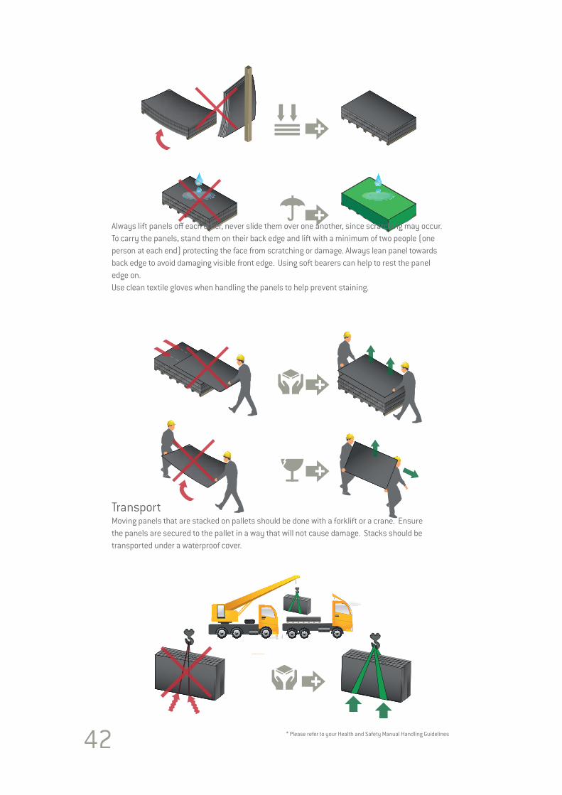
Always lift panels off each other, never slide them over one another, since scratching may occur. To carry the panels, stand them on their back edge and lift with a minimum of two people (one person at each end) protecting the face from scratching or damage. Always lean panel towards back edge to avoid damaging visible front edge. Using soft bearers can help to rest the panel edge on.Use clean textile gloves when handling the panels to help prevent staining.
TransportMoving panels that are stacked on pallets should be done with a forklift or a crane. Ensure the panels are secured to the pallet in a way that will not cause damage. Stacks should be transported under a waterproof cover.
* Please refer to your Health and Safety Manual Handling Guidelines
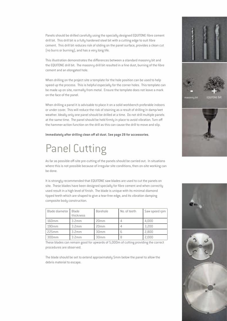
Panels should be drilled carefully using the specially designed EQUITONE fibre cement drill bit. This drill bit is a fully hardened steel bit with a cutting edge to suit fibre cement. This drill bit reduces risk of sliding on the panel surface, provides a clean cut (no burrs or burning), and has a very long life.
This illustration demonstrates the differences between a standard masonry bit and the EQUITONE drill bit. The masonry drill bit resulted in a fine dust, burning of the fibre cement and an elongated hole.
When drilling on the project site a template for the hole position can be used to help speed up the process. This is helpful especially for the corner holes. This template can be made up on site, normally from metal. Ensure the template does not leave a mark on the face of the panel.
When drilling a panel it is advisable to place it on a solid workbench preferable indoors or under cover. This will reduce the risk of staining as a result of drilling in damp/wet weather. Ideally only one panel should be drilled at a time. Do not drill multiple panels at the same time. The panel should be held firmly in place to avoid vibration. Turn off the hammer-action function on the drill as this can cause the drill to move and slip.
Immediately after drilling clean off all dust. See page 28 for accessories.
Panel CuttingAs far as possible off-site pre-cutting of the panels should be carried out. In situations where this is not possible because of irregular site conditions, then on-site working can be done.
It is strongly recommended that EQUITONE saw blades are used to cut the panels on site. These blades have been designed specially for fibre cement and when correctly used result in a high level of finish. The blade is unique with its minimal diamond tipped teeth which are shaped to give a tear-free edge, and its vibration damping composite body construction.
Blade diameter Blade thickness
Borehole No. of teeth Saw speed rpm
160mm 3.2mm 20mm 4 4,000190mm 3.2mm 20mm 4 3,200225mm 3.2mm 30mm 6 2,800300mm 3.2mm 30mm 8 2,000
These blades can remain good for upwards of 5,000m of cutting providing the correct procedures are observed.
The blade should be set to extend approximately 5mm below the panel to allow the debris material to escape.
- +masonry bit EQUITONE bit
44
For large amounts of cutting on site, it is recommended that a Festo AXT 50 LA or Mafell PSS 3100 SE Portable Panel Saw System is used to cut the panels with an EQUITONE blade. Both of these saws have a guide rail which ensures the saw stays steady and gives straight cuts. Each of these saws also has an enclosed blade and vacuum system to reduce the dust nuisance and ensure good health and safety practices.
The EQUITONE panels are normally placed face down and the cutting is from the back side. Therefore, it is important that the workbench has a clean and soft material covering it to prevent scratching and marking of the panels.
As with the drilling process, when cutting the panels it is advisable to place the panel on a solid workbench preferably indoors or under cover. This will reduce the risk of staining as a result of cutting in damp/wet weather.Ideally only one panel should be cut at a time. Do not cut multiple panels together at the same time. The panel should be held firmly in place to avoid vibration.
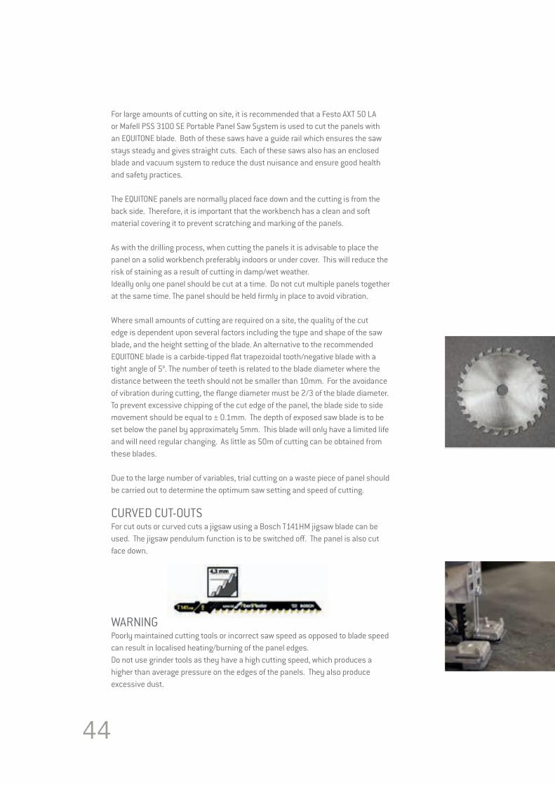
Where small amounts of cutting are required on a site, the quality of the cut edge is dependent upon several factors including the type and shape of the saw blade, and the height setting of the blade. An alternative to the recommended EQUITONE blade is a carbide-tipped flat trapezoidal tooth/negative blade with a tight angle of 5°. The number of teeth is related to the blade diameter where the distance between the teeth should not be smaller than 10mm. For the avoidance of vibration during cutting, the flange diameter must be 2/3 of the blade diameter. To prevent excessive chipping of the cut edge of the panel, the blade side to side movement should be equal to ± 0.1mm. The depth of exposed saw blade is to be set below the panel by approximately 5mm. This blade will only have a limited life and will need regular changing. As little as 50m of cutting can be obtained from these blades.
Due to the large number of variables, trial cutting on a waste piece of panel should be carried out to determine the optimum saw setting and speed of cutting.
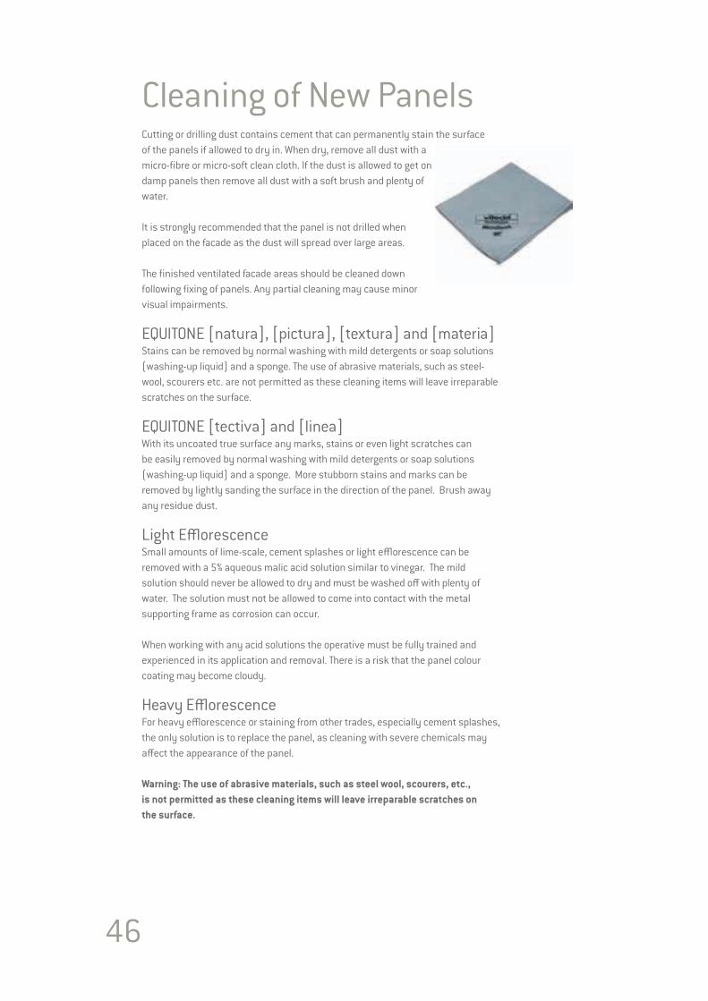
CURVED CUT-OUTSFor cut outs or curved cuts a jigsaw using a Bosch T141HM jigsaw blade can be used. The jigsaw pendulum function is to be switched off. The panel is also cut face down.
WARNINGPoorly maintained cutting tools or incorrect saw speed as opposed to blade speed can result in localised heating/burning of the panel edges.Do not use grinder tools as they have a high cutting speed, which produces a higher than average pressure on the edges of the panels. They also produce excessive dust.

EQUITONE Edge TreatmentEdge finishIt is recommended to sand/chamfer the decorative edge/corner of the panels to remove the sharp arris, after cutting them to size. This reduces the possibility of damage and improves their appearance. A block of wood, approx. 400 x 100mm in size, with a piece of sandpaper (80-grit) affixed to it can be used to sand the edges or a diamond electrostatic block can be used.
Application of Luko (EQUITONE [natura] and Pro coated [natura] only)1. Observe the edge finish recommendations (as outlined above)
2. Edges must be clean and dry
3. Pour sufficient Luko solution into tray provided
4. Position applicator right-angled to the edge and run twice along the edge with moderate pressure
5. Luko should not flow onto the face of the panel, wipe off immediately with damp cloth
6. Check Luko has been applied along the entire length of the sheet
7. Replace applicator when worn
Guidance for Luko solutionFinishing must be applied sheet by sheet not in a stack/mass application
Shake Luko solution well before dispensing into the tray
Do not reuse Luko solution once it has been in the tray for over 2 hours
Luko solution must not be diluted
The complete impregnation of the edges of the cladding board prevents moisture absorption along the edges and any resulting temporary discolouring of the visible surface at the edges. The Luko solution must completely cover the cut edge and will show as a complete glossy finish to the cut edge
Do not allow to freeze – should be stored between 5° - 25°C
Use within 3 months of supply.
46
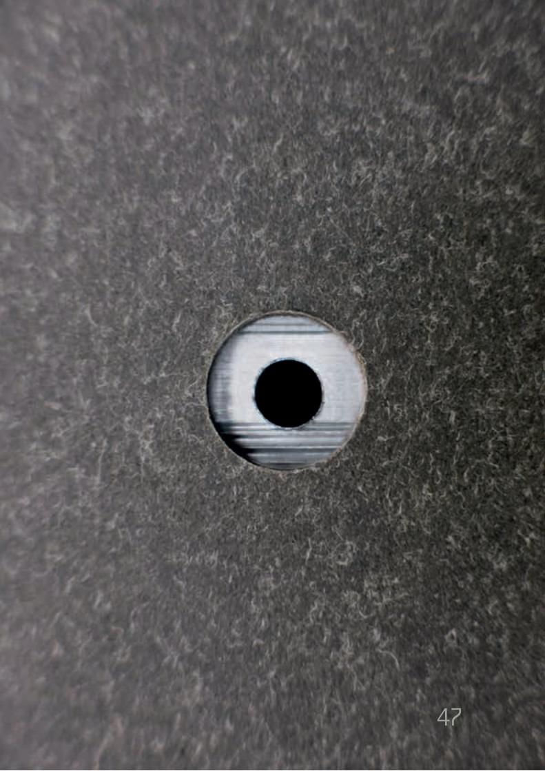
Cleaning of New PanelsCutting or drilling dust contains cement that can permanently stain the surface of the panels if allowed to dry in. When dry, remove all dust with a micro-fibre or micro-soft clean cloth. If the dust is allowed to get on damp panels then remove all dust with a soft brush and plenty of water.
It is strongly recommended that the panel is not drilled when placed on the facade as the dust will spread over large areas.
The finished ventilated facade areas should be cleaned down following fixing of panels. Any partial cleaning may cause minor visual impairments.
EQUITONE [natura], [pictura], [textura] and [materia]Stains can be removed by normal washing with mild detergents or soap solutions (washing-up liquid) and a sponge. The use of abrasive materials, such as steel-wool, scourers etc. are not permitted as these cleaning items will leave irreparable scratches on the surface.
EQUITONE [tectiva] and [linea]With its uncoated true surface any marks, stains or even light scratches can be easily removed by normal washing with mild detergents or soap solutions (washing-up liquid) and a sponge. More stubborn stains and marks can be removed by lightly sanding the surface in the direction of the panel. Brush away any residue dust.
Light Efflorescence Small amounts of lime-scale, cement splashes or light efflorescence can be removed with a 5% aqueous malic acid solution similar to vinegar. The mild solution should never be allowed to dry and must be washed off with plenty of water. The solution must not be allowed to come into contact with the metal supporting frame as corrosion can occur.
When working with any acid solutions the operative must be fully trained and experienced in its application and removal. There is a risk that the panel colour coating may become cloudy.
Heavy EfflorescenceFor heavy efflorescence or staining from other trades, especially cement splashes, the only solution is to replace the panel, as cleaning with severe chemicals may affect the appearance of the panel.
Warning: The use of abrasive materials, such as steel wool, scourers, etc., is not permitted as these cleaning items will leave irreparable scratches on the surface.
47
48
INSTALLATION OF EQUITONE Section 4
INSTALLATION OF EQUITONE
49
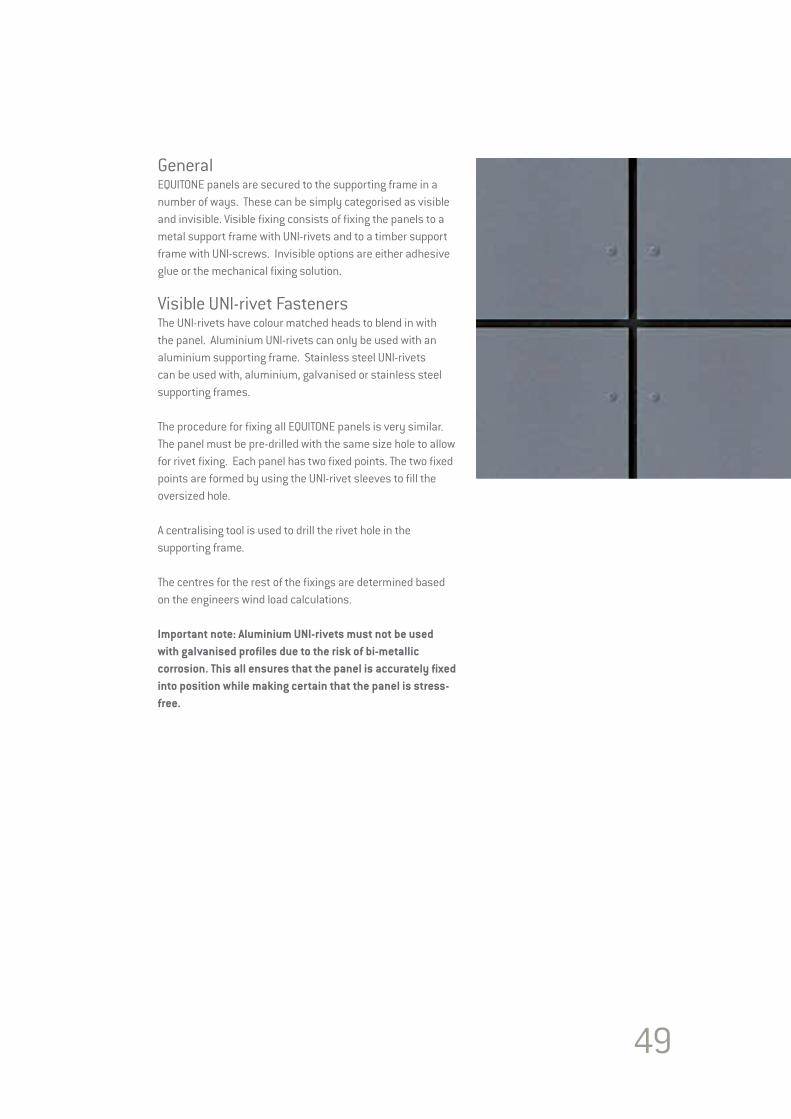
GeneralEQUITONE panels are secured to the supporting frame in a number of ways. These can be simply categorised as visible and invisible. Visible fixing consists of fixing the panels to a metal support frame with UNI-rivets and to a timber support frame with UNI-screws. Invisible options are either adhesive glue or the mechanical fixing solution.
Visible UNI-rivet FastenersThe UNI-rivets have colour matched heads to blend in with the panel. Aluminium UNI-rivets can only be used with an aluminium supporting frame. Stainless steel UNI-rivets can be used with, aluminium, galvanised or stainless steel supporting frames.
The procedure for fixing all EQUITONE panels is very similar.The panel must be pre-drilled with the same size hole to allow for rivet fixing. Each panel has two fixed points. The two fixed points are formed by using the UNI-rivet sleeves to fill the oversized hole.
A centralising tool is used to drill the rivet hole in the supporting frame.
The centres for the rest of the fixings are determined based on the engineers wind load calculations.
Important note: Aluminium UNI-rivets must not be used with galvanised profiles due to the risk of bi-metallic corrosion. This all ensures that the panel is accurately fixed into position while making certain that the panel is stress-free.

50
Visible Screw FastenersEQUITONE panels can be easily screw fixed to a timber batten supporting frame. Ensure that all timber battens are covered with either an EPDM or aluminium cover strip. The batten must be adequately sized so that the screw is a minimum of 15mm in from the edge.
EQUITONE Stainless Steel T 20 torx screws are available with the heads coloured to match the panels.
The minimum screw depth of 25mm into the timber is recommended.
Preparation of EQUITONE PanelsCarefully mark the position of the holes on the face of the panel. Drill all holes with an EQUITONE drill bit.
Panels are to be drilled prior to lifting into place on the facade. A corner metal template can be employed to speed up drilling. This can be made-up on site. All drilling is best done on a solid workbench. Do not drill multiple panels together. Drill one at a time to ensure accurate positioning of the holes.
Immediately clean all dust and pencil marks from the panel.
All fasteners must be inserted perpendicular to the panel surface, and must not be over tightened to impede the free movement of the panel.

51
RIVET FIXINGFixed/Stop point – Sliding/Go point – Rivet FixedWhere panels are fastened to the supporting frame with a combination of fixed/stop and sliding/go points, each panel no matter what size will have 2 fixed/stop points and the rest left as sliding/go points.
The 2 fixed/stop points support the weight of the panel and ensure the panel stays in position and prevents rotation of the panel. The sliding/go points resist the wind loading, while accommodating any panel or support frame movement.
The choice of where the fixed/stop points are to be is important to prevent any risk of the panel cracking.
Selection of Fixed/Stop PointThe two fixed/stop points should never occur on the same profile. The two fixed/stop points must be located near the horizontal centre line of the panel. If there is no central fixing then use the next row closest to the centre line.
This means that two profiles are needed. This is straight forward where there are at least two profiles in the middle area of the panel.
More commonly, there is only one profile in the middle area of the panel. Here, the rule-of-thumb is that the fixed/stop points are located to the centre of the panel and to the left joint profile. Alternatively they can be located to the centre and right joint profile. Whichever one is used all panels must be the same.
It should never be allowed that the fixed/stop point of two adjoining panels occur on the same joint profile.
In situations where narrow panels with only two side fixings are used and the fixed/stop points of adjacent panels will be next to each other, the support frame will need to be amended. The metal support frame behind the vertical joint which is usually a T profile will have to be substituted with two L profiles. This will separate any panel connection. This may also result in having a “U” bracket instead of the normal angle bracket.
Fixed/stop point
Sliding/go point

52
EQUITONE may be face fixed to metal supporting frame using the EQUITONE UNI-rivet. The UNI-rivets have colour matched heads to blend in with the panel. Aluminium UNI-rivets can only be used with aluminium supporting frame. Stainless steel UNI-rivets can be used with, aluminium, galvanised or stainless steel supporting frames.
ProcedureThe procedure for fixing all EQUITONE panels is the same. The panel must be pre drilled with an 11mm diameter size hole to allow for rivet fixing.
Each panel has two fixed/stop points. The two fixed/stop points are formed by using the red UNI-rivet sleeves to fill the oversized hole. No red sleeve is used for the sliding/go holes. A centralising tool is used to drive the rivet hole in the supporting frame. A UNI-rivet setting tool which fits to the end of the rivet gun can be used to prevent scratching the rivet head and ensure the correct placement of the UNI-rivet.
Hole positionThe position of the holes is as follows.• From the horizontal edges of the panel the dimension is 70mm -> 100mm.• From the side edges of the panel the dimension is 30mm -> 100mm.
Placing the corner UNI-rivets 80mm from the horizontal edge 30mm from the vertical edges visually is the preferred location.
The centres for the rest of the fixings are determined based on the engineers wind load calculations.
Important note: Aluminium UNI-rivets must not be used with galvanised profiles due to the risk of bi-metallic corrosion. This ensures that the panel is accurately fixed into position while making certain that the panel is stress-free.
EQUITONE UNI-rivet
EQUITONE UNI-rivet RED STOP point sleeve
100mm
70mm
100mm 30mm
Corner rivet
80mm
30mm

Installation procedurePlace the foam tape onto the support frame metal profiles.
Position the pre drilled panel on a support rail and against the support frame, adjust to correct line and clamp into place. Starting with the red Fixed/Stop points, insert 4.1mm centralising tool into the holes and drill through support frame profiles, Remove all debris.
Red stop points – (Fixed/Stop points)Place the EQUITONE UNI-rivet into its red rivet sleeve collar (hole reducer) and place into rivet gun. Insert UNI-rivet with rivet sleeve collar (hole reducer) into pre drilled hole and pop the rivet. The UNI-rivet must lie flat on the facade panel.
Green go points – (Sliding/Go points)Continue with the Sliding/Go points, insert 4.1mm centralising tool into the holes and rill through support frame profiles. Remove any debris.
Insert only the EQUITONE UNI-rivet into the rivet gun and place into the pre drilled hole and pop the rivet. The UNI-rivet must lie flat on the facade panel. Fix Sliding/Go points after Fixed/Stop points are completed.
SCREW FASTENERS TO WOODUNI-screwEQUITONE UNI-screws for wood are A2 (304) stainless steel ISR T20 hex socket cap screw with a 15mm diameter head. The head of the UNI-screw is available coloured to match the panels. An uncoated UNI-screw is also available.• 5.5 x 35mm for 8mm facade panels • 5.5 x 45mm for 12mm facade panels.
ProcedureEQUITONE can be easily screw fixed to a timber batten supporting frame. Ensure that all timber battens are covered with an EPDM cover strip. The EPDM must overhang each side of the batten by a minimum of 5mm. The batten must be adequately sized to meet local regulations paying attention to the minimum distance requirement between the screw and the batten edge. Check local recommendations for the minimum screw depth into the timer.Drill the panel with 7mm diameter holes.
Hole PositionThe position of the holes is as follows:• From the horizontal edges of the panel the dimension is 70mm -> 100mm. • From the side edges of the panel the dimension is 25mm ->100mm.
Placing the corner screws 80mm from the horizontal edge 25mm from the vertical edges visually is the preferred location.
Centres for the rest of the fixings are determined based on the engineers wind load calculations.
This all ensures that the panel is accurately fixed into position while making certain that the panel is stress-free.

VISIBLE RIVET FIXINGEQUITONE [linea]* POSITION OF FIXING POINTSFor technical reasons the fasteners have to be aligned with the deeper part of the grooved surface. Therefore the ribs at the location of the fasteners have to be milled first. To mill the ribs a special drill/milling tool is used. The tool is equipped with a drill in order to drill andmill the hole in one movement. The milling tool comes in different versions depending on the drill diameter.
From an aesthetic point of view it is recommended to align the fixing points with the ribs of the panel. Doing so, the head of the fasteners are the least visible. This will result in a wider support up to 140 mm.
Other positions of the fixings as described above are also possible and supported.
* The fixings Marley Eternit supply to secure our facade panels, along with Fischer’s Tergo+ Undercut Anchors used to mechanical secret fix our EQUITONE [linea] and [tectiva] panels, have been developed and produced in conjunction with our facade materials to be of the highest quality for the longevity and durability of both the panels and fixings.
Any facade panel not secured with either Marley Eternit fixings or Fischer’s Tergo+ Undercut Anchors is deemed to be not installed in accordance with Marley Eternit recommendations and in the event of a material failure, Marley Eternit would not be responsible for any claim or material cost arising from incorrect use of fixings.
For further information, please contact Marley Eternit’s Technical Advisory Service Tel: 01283 722588.
54
55
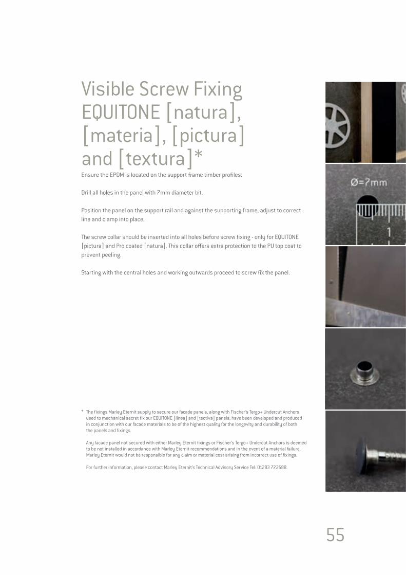
Visible Screw Fixing EQUITONE [natura], [materia], [pictura] and [textura]*Ensure the EPDM is located on the support frame timber profiles.
Drill all holes in the panel with 7mm diameter bit.
Position the panel on the support rail and against the supporting frame, adjust to correct line and clamp into place.
The screw collar should be inserted into all holes before screw fixing - only for EQUITONE [pictura] and Pro coated [natura]. This collar offers extra protection to the PU top coat to prevent peeling.
Starting with the central holes and working outwards proceed to screw fix the panel.
* The fixings Marley Eternit supply to secure our facade panels, along with Fischer’s Tergo+ Undercut Anchors used to mechanical secret fix our EQUITONE [linea] and [tectiva] panels, have been developed and produced in conjunction with our facade materials to be of the highest quality for the longevity and durability of both the panels and fixings.
Any facade panel not secured with either Marley Eternit fixings or Fischer’s Tergo+ Undercut Anchors is deemed to be not installed in accordance with Marley Eternit recommendations and in the event of a material failure, Marley Eternit would not be responsible for any claim or material cost arising from incorrect use of fixings.
For further information, please contact Marley Eternit’s Technical Advisory Service Tel: 01283 722588.
56
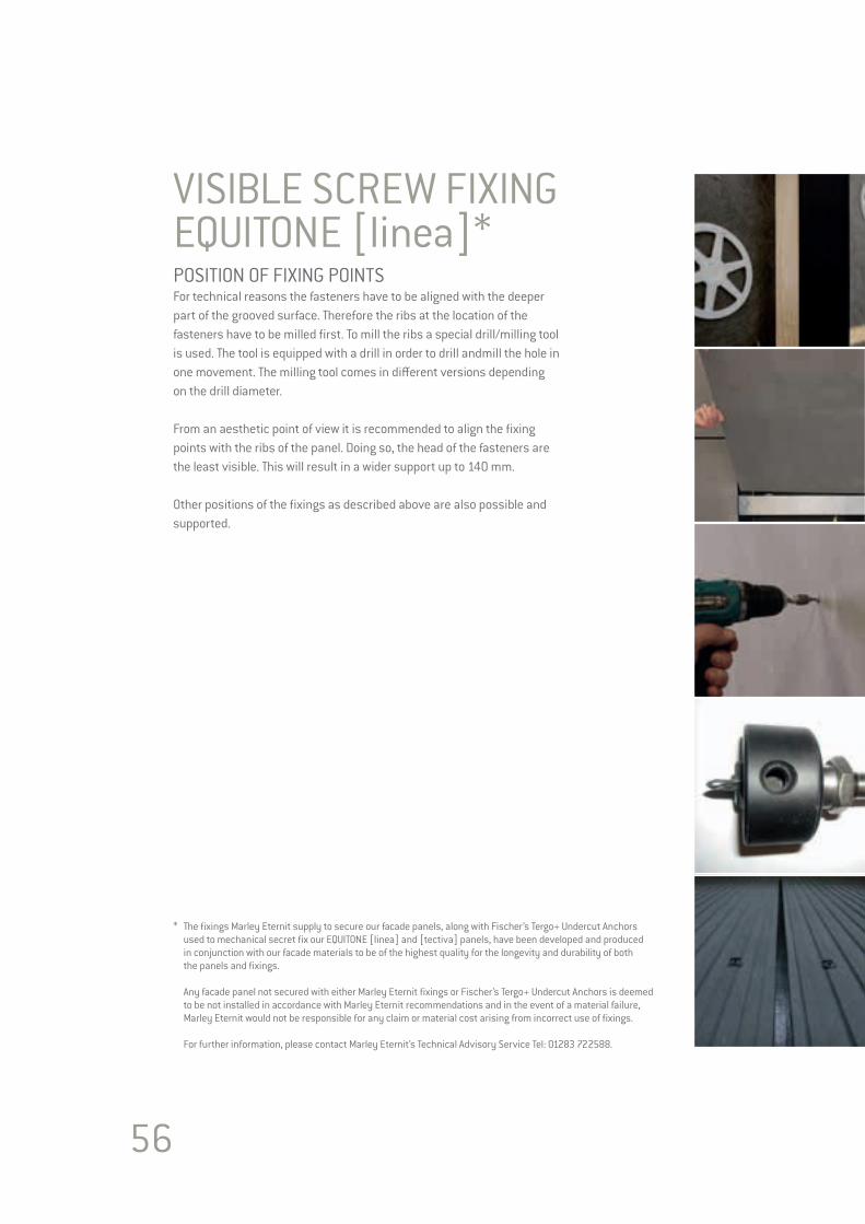
VISIBLE SCREW FIXINGEQUITONE [linea]*POSITION OF FIXING POINTSFor technical reasons the fasteners have to be aligned with the deeper part of the grooved surface. Therefore the ribs at the location of the fasteners have to be milled first. To mill the ribs a special drill/milling tool is used. The tool is equipped with a drill in order to drill andmill the hole in one movement. The milling tool comes in different versions depending on the drill diameter.
From an aesthetic point of view it is recommended to align the fixing points with the ribs of the panel. Doing so, the head of the fasteners are the least visible. This will result in a wider support up to 140 mm.
Other positions of the fixings as described above are also possible and supported.
* The fixings Marley Eternit supply to secure our facade panels, along with Fischer’s Tergo+ Undercut Anchors used to mechanical secret fix our EQUITONE [linea] and [tectiva] panels, have been developed and produced in conjunction with our facade materials to be of the highest quality for the longevity and durability of both the panels and fixings.
Any facade panel not secured with either Marley Eternit fixings or Fischer’s Tergo+ Undercut Anchors is deemed to be not installed in accordance with Marley Eternit recommendations and in the event of a material failure, Marley Eternit would not be responsible for any claim or material cost arising from incorrect use of fixings.
For further information, please contact Marley Eternit’s Technical Advisory Service Tel: 01283 722588.
57
Glue FixingIt is important that Glue Fixing is carried out in strict accordance with the glue suppliers instructions by certified installers. Please note that recommendations and fixing procedures differ between suppliers. The following information is given only as a guideline and must not be taken as a complete recommendation.
For information on our recommended adhesive partners, please contact Marley Eternit’s Technical Advisory Service Tel: 01283 722588.
Please note that not all glue systems are suitable for all panels on all support frame options. Therefore, it is important to choose the correct glue for the application.
As there are many suppliers of glue, we would always advise that the installer only works with certified products, which have been tested with EQUITONE panels.
The maximum height can be restricted by the conditions of the supplier of the glue or by local regulation legislation.
All suppliers will have their conditions or restrictions for working on site. These may be: • Recommended range of working temperature – Example: +5° and + 35°C. This must remain within these values for at least 5-6 hours after application.• The surfaces to be bonded must be clean, dry, and free from dust and grease. The use of cleaners will be needed. • Restrictions on the Relative humidity – Example: not to be higher than 75% • The substrate temperature must be 3°C higher than the dew point.
RequirementsThe deflection of any cladding panel may not exceed 1/100 of the span of the EQUITONE panel between supports plus any overhang or cantilever, if there is one.
CleaningAny unwanted or excess adhesive left on the profiles must be removed immediately using the suppliers cleaning agent, as it can only be removed mechanically if left until later.
Consult the glue supplier if adhesive or primer is left on the surface of any panel.
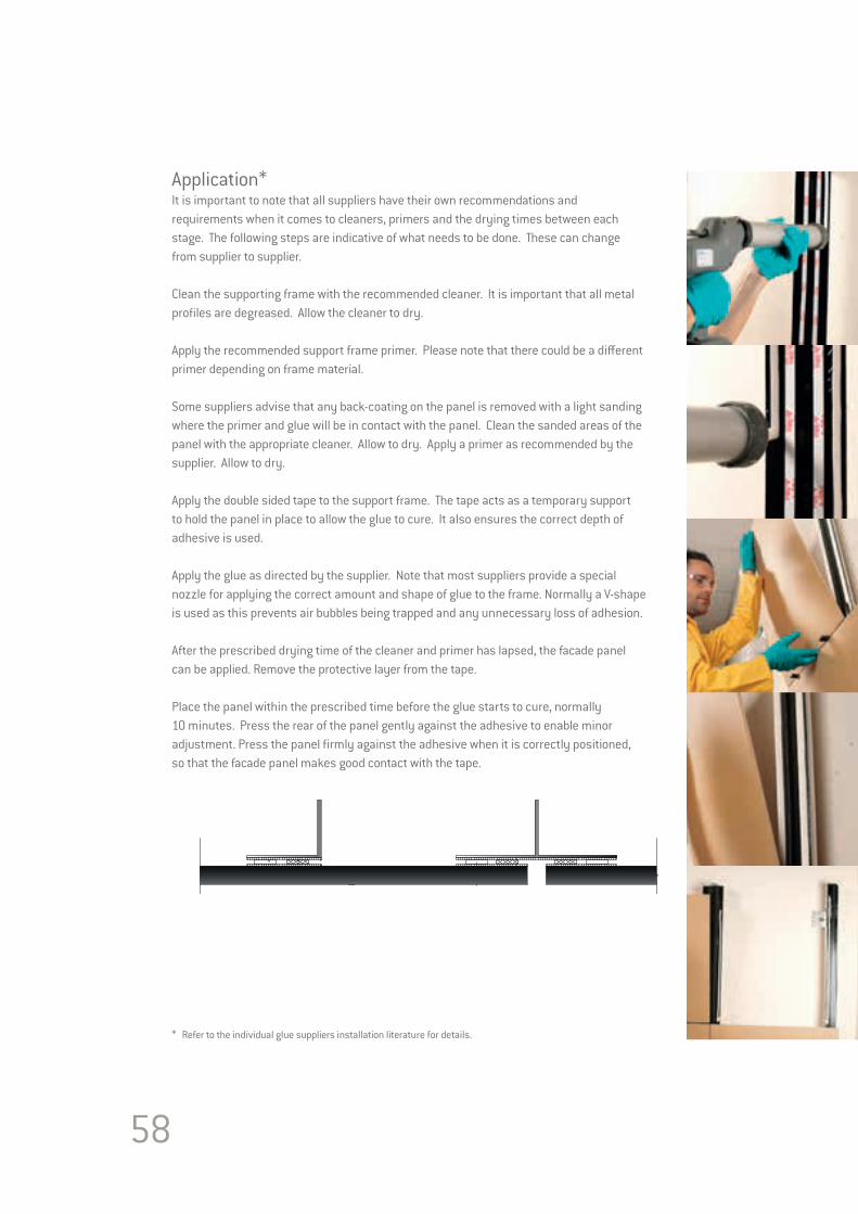
58
Application*It is important to note that all suppliers have their own recommendations and requirements when it comes to cleaners, primers and the drying times between each stage. The following steps are indicative of what needs to be done. These can change from supplier to supplier.
Clean the supporting frame with the recommended cleaner. It is important that all metal profiles are degreased. Allow the cleaner to dry.
Apply the recommended support frame primer. Please note that there could be a different primer depending on frame material.
Some suppliers advise that any back-coating on the panel is removed with a light sanding where the primer and glue will be in contact with the panel. Clean the sanded areas of the panel with the appropriate cleaner. Allow to dry. Apply a primer as recommended by the supplier. Allow to dry.
Apply the double sided tape to the support frame. The tape acts as a temporary support to hold the panel in place to allow the glue to cure. It also ensures the correct depth of adhesive is used.
Apply the glue as directed by the supplier. Note that most suppliers provide a special nozzle for applying the correct amount and shape of glue to the frame. Normally a V-shape is used as this prevents air bubbles being trapped and any unnecessary loss of adhesion.
After the prescribed drying time of the cleaner and primer has lapsed, the facade panel can be applied. Remove the protective layer from the tape.
Place the panel within the prescribed time before the glue starts to cure, normally 10 minutes. Press the rear of the panel gently against the adhesive to enable minor adjustment. Press the panel firmly against the adhesive when it is correctly positioned, so that the facade panel makes good contact with the tape.
* Refer to the individual glue suppliers installation literature for details.
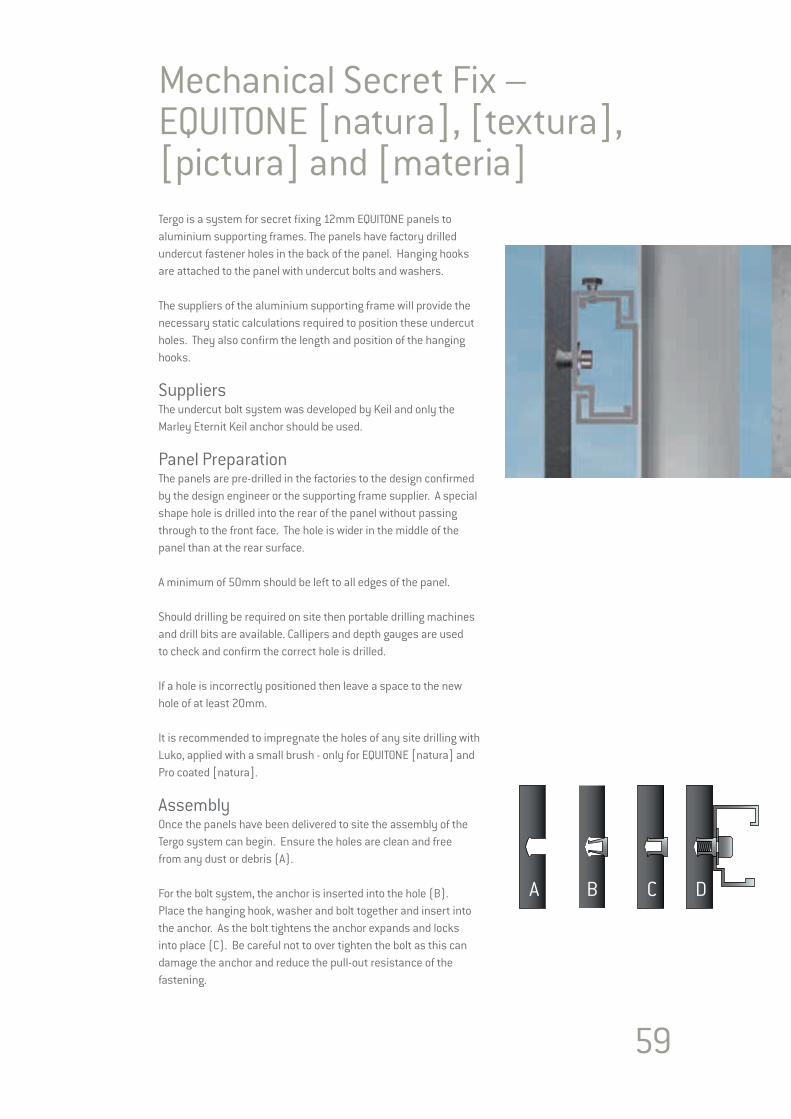
59
Tergo is a system for secret fixing 12mm EQUITONE panels to aluminium supporting frames. The panels have factory drilled undercut fastener holes in the back of the panel. Hanging hooks are attached to the panel with undercut bolts and washers.
The suppliers of the aluminium supporting frame will provide the necessary static calculations required to position these undercut holes. They also confirm the length and position of the hanging hooks.
SuppliersThe undercut bolt system was developed by Keil and only the Marley Eternit Keil anchor should be used. Panel PreparationThe panels are pre-drilled in the factories to the design confirmed by the design engineer or the supporting frame supplier. A special shape hole is drilled into the rear of the panel without passing through to the front face. The hole is wider in the middle of the panel than at the rear surface.
A minimum of 50mm should be left to all edges of the panel.
Should drilling be required on site then portable drilling machines and drill bits are available. Callipers and depth gauges are used to check and confirm the correct hole is drilled.
If a hole is incorrectly positioned then leave a space to the new hole of at least 20mm.
It is recommended to impregnate the holes of any site drilling with Luko, applied with a small brush - only for EQUITONE [natura] and Pro coated [natura].
AssemblyOnce the panels have been delivered to site the assembly of the Tergo system can begin. Ensure the holes are clean and free from any dust or debris (A).
For the bolt system, the anchor is inserted into the hole (B). Place the hanging hook, washer and bolt together and insert into the anchor. As the bolt tightens the anchor expands and locks into place (C). Be careful not to over tighten the bolt as this can damage the anchor and reduce the pull-out resistance of the fastening.
A B C D
Mechanical Secret Fix – EQUITONE [natura], [textura], [pictura] and [materia]
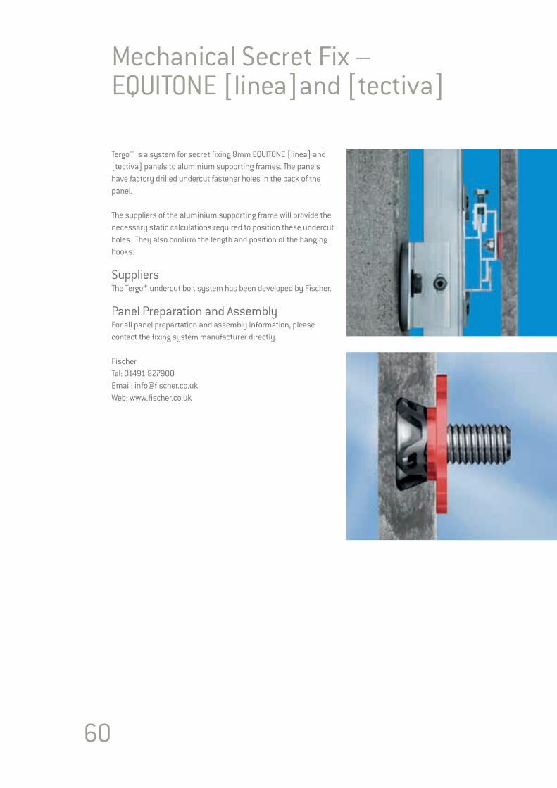
60
Tergo+ is a system for secret fixing 8mm EQUITONE [linea] and [tectiva] panels to aluminium supporting frames. The panels have factory drilled undercut fastener holes in the back of the panel.
The suppliers of the aluminium supporting frame will provide the necessary static calculations required to position these undercut holes. They also confirm the length and position of the hanging hooks.
SuppliersThe Tergo+ undercut bolt system has been developed by Fischer. Panel Preparation and AssemblyFor all panel prepartation and assembly information, please contact the fixing system manufacturer directly.
FischerTel: 01491 827900 Email: [email protected]: www.fischer.co.uk
Mechanical Secret Fix – EQUITONE [linea]and [tectiva]
Tergo+ secret fi xingby fi scher undercut technology for EQUITONE [linea] and EQUITONE [tectiva] fi bre cement facade panels
Tech
nica
l sub
ject
to c
hang
e · v
ersi
on 1
50
70
2
Technical data
Drilling / anchor setting
Application exampleAnchor in panelTergo+, fi bre cement
FrameworkFacade panel with Tergo+ fi xing suspended on suitable support framework
Fibre cement facade
InstallationAfter making the undercut hole, the anchor is set simultanously with attachment parts with a power tool.
Advantages / benefi ts Fixings not visible from front of facade Stress-free fi xing Statically optimised position of anchor Large panel sizes possible High load capability Optimised for long-life Independent of weather
Product descriptionUndercut anchor for EQUITONE [linea] and EQUITONE [tectiva] fi bre cement. Application with bracket systems or other attachment parts.
Type Item min
. EQ
UIT
ON
E pa
nel
thic
knes
s*
Inst
alle
d an
chor
le
ngth
mm
a
Dril
l hol
e Ø
mm
Col
our c
ode
of s
him
w
ashe
r
Anc
hora
ge d
epth
mm
Thre
ad d
iam
eter
Bol
t pro
ject
ion
leng
th b
Box
qua
ntity
piec
es
Tergo+ 11x6 M6/T/10 PA 532 641 8 8 11 red 6 M6 10 250
Tergo+ 11x6 M6/T/13 PA 532 642 8 8 11 red 6 M6 13 250
2,5
fi scher fi xings UK Ltd Whitely Road · Wallingford · Oxon · OX10 9AT Tel: 01491 827900 · Email: info@fi scher.co.uk Web: www.fi scher.co.uk
Marley Eternit Lichfi eld Road, Branston, Burton-upon Trent, DE14 3HD Tel: 01283 722588 · Email: [email protected] www.marleyeternit.co.uk
Institut für MassivbauTechnische Universität
Darmstadt
Pending
* for EQUITONE [linea] and EQUITONE [tectiva] only
Terg
o+
secre
t fi xing
by
fi sche
r un
de
rcut te
chn
olo
gy
for
EQU
ITO
NE [lin
ea] an
d EQ
UIT
ON
E [tectiva]
fi bre
cem
en
t facade
pan
els
Technical subject to change · version 150702
Techn
ical data
Drillin
g / anch
or setting
Application
example
An
chor in
panel
Tergo+, fi bre cem
ent
Framew
orkFacade panel w
ith Tergo+
fi xing suspended on suitable support fram
ework
Fibre cemen
t facade
Installation
After m
aking the undercut hole, the anchor is set simultanously
with attachm
ent parts with a pow
er tool.
Advan
tages / benefi ts
Fixings not visible from front of facade
Stress-free fi xing Statically optim
ised position of anchor Large panel sizes possible H
igh load capability O
ptimised for long-life
Independent of weather
Product descrip
tionU
ndercut anchor for EQU
ITON
E [linea] and EQU
ITON
E [tectiva] fi bre cem
ent. Application w
ith bracket systems or other attachm
ent parts.
TypeItem
min. EQUITONE panel thickness*
Installed anchor length mm a
Drill hole Ø mm
Colour code of shim washer
Anchorage depth mm
Thread diameter
Bolt projection length b
Box quantitypieces
Tergo+ 1
1x6
M6
/T/10
PA5
32
64
18
81
1red
6M
61
02
50
Tergo+ 1
1x6
M6
/T/13
PA5
32
64
28
81
1red
6M
61
32
50
2,5
fi scher fi xin
gs UK
Ltd W
hitely Road · W
allingford · Oxon · O
X1
0 9
AT
Tel: 01
49
1 8
27
90
0 · Em
ail: info@fi scher.co.uk
Web: w
ww
.fi scher.co.uk
Marley Etern
it Lichfi eld R
oad, Branston, B
urton-upon Trent, DE1
4 3
HD
Tel: 0
12
83
72
25
88
· Email: info@
marleyeternit.co.uk
ww
w.m
arleyeternit.co.uk
Institut für MassivbauTechnische Universität
Darmstadt
Pending
* for EQU
ITON
E [linea] and EQU
ITON
E [tectiva] only

61
Sequence for Installing the PanelsA sequence or method of placing the EQUITONE panels on the facade must be put in place to ensure the risk of damage to the panels is minimised. EQUITONE panels are a finished facade product and are generally the last major cladding material to be fitted. Care and attention is required should other trades (painting or rendering) need to follow on after the panel is fitted. The panels must then be protected. Stains from coloured renders can be difficult to remove and with some colours replacement of the panels is the only remedy.
The Installer needs to survey the main supporting structure, checking line, level and fixing points. Report any discrepancies immediately to the Main Contractor/Architect, if the structure will not allow the required accuracy or security of erection. Set out the datum points, lines and levels for a complete elevation at the same time.
Refer to the Architect’s elevation drawings for layout of joints and line of fasteners. Note the relationship between the fixings and openings such as windows.
Experience has shown that the best sequence in placing the EQUITONE panels that will have visible fasteners is to commence at the top of the facade and work downwards. This procedure of installing the panels top-down is also the preferred method for glue fixing systems.
Due to the nature of the Tergo secret fixing system it is recommended that the panels are installed from the ground upwards. The panels are supported individually and do not rest on one another, therefore not causing any damage to the panel edges. It is also not practical to adjust and lock the Tergo hangers unless the installer is working from above the panel.
Special installation situationFor limited applications, sometimes it may be necessary to commence cladding from the base of the facade. This can be done successfully but requires the installer to take extra care and attention to prevent damaging the edge of the panel. The most likely damage will be the top edge of the lower panels. As the weight of the upper panel will be resting on the spacers which in turn will be resting on the lower panel. Therefore, removal of the joint spacers must be done with utmost care. One suggestion is to use an 8mm spacer and wrap a 1mm rubber strip around the top face, back edge and bottom face of the spacer. Remove the spacer first and then the rubber strip. The rubber strip protects the edges of the panels as the spacer is being removed.
Mobile Elevated Working PlatformShould the panels need to be fixed from a Mobile Elevated Working Platform (MEWP) then the panels can be installed in a vertical stacked sequence.
Commence in the same fashion as above at the top of the facade. Mark the position of the bottom edge of the top panel and support the panel on a temporary short horizontal rail. Proceed down the facade and not across. A vertical rail clamped to the joint profile can help in maintaining a straight vertical line as work proceeds down the facade. Once the first column of panels is in place, simply move the MEWP to its next position and commence again at the top of the facade. This time allow for the vertical joint in the measurement to the next panel edge.
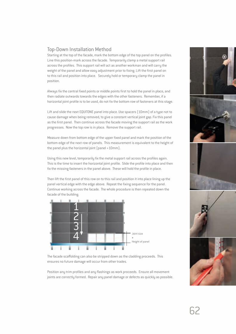
62
Top-Down Installation MethodStarting at the top of the facade, mark the bottom edge of the top panel on the profiles. Line this position-mark across the facade. Temporarily clamp a metal support rail across the profiles. This support rail will act as another workman and will carry the weight of the panel and allow easy adjustment prior to fixing. Lift the first panel on to this rail and position into place. Securely hold or temporary clamp the panel in position.
Always fix the central fixed points or middle points first to hold the panel in place, and then radiate outwards towards the edges with the other fasteners. Remember, if a horizontal joint profile is to be used, do not fix the bottom row of fasteners at this stage.
Lift and slide the next EQUITONE panel into place. Use spacers (10mm) of a type not to cause damage when being removed, to give a constant vertical joint gap. Fix this panel as the first panel. Then continue across the facade moving the support rail as the work progresses. Now the top row is in place. Remove the support rail. Measure down from bottom edge of the upper fixed panel and mark the position of the bottom edge of the next row of panels. This measurement is equivalent to the height of the panel plus the horizontal joint (panel +10mm).
Using this new level, temporarily fix the metal support rail across the profiles again. This is the time to insert the horizontal joint profile. Slide the profile into place and then fix the missing fasteners in the panel above. These will hold the profile in place.
Then lift the first panel of this row on to this rail and position it into place lining up the panel vertical edge with the edge above. Repeat the fixing sequence for the panel. Continue working across the facade. The whole procedure is then repeated down the facade of the building.
The facade scaffolding can also be stripped down as the cladding proceeds. This ensures no future damage will occur from other trades.
Position any trim profiles and any flashings as work proceeds. Ensure all movement joints are correctly formed. Repair any panel damage or defects as quickly as possible.
Joint size+Height of panel
1234
63
64
SUPPORTING FRAME DESIGN
Section 5SUPPORTING FRAMEDESIGN

65
EQUITONE panels are strong yet light, which reduces the amount of supporting frame needed compared with other materials. Certification for the structural stability of any supporting frame should be in accordance with local building regulations and must be obtained by the building’s owner or his representatives, namely the project engineer. RequirementsIn any approval of structural stability, it is advised that a minimum of 20mm should be added to the planned cavity and insulation thickness between the wall and cladding, to allow for dimensional variations in the backing wall. This amount may be changed if on-site measurements show that the dimensional variation is less than this.
Whichever supporting frame is used, the wall should be checked by the installer prior to installation to confirm that it is flat and level and to ensure that the correct fixings and details are used. Any discrepancies should be referred to the design team.
Structural DesignAll components of the external cladding must be designed according to the safety factors and permissible design load as stipulated in the Eurocodes. Where the Eurocodes are not in use, then local standards or building regulations must be adhered to. The load-bearing capacity of fixing systems and fasteners that are not covered by the standards or building regulations approvals must be tested and certified in accordance with these local regulations.
Support Frame LayoutThe most common arrangement for the panel’s support is onto metal or timber vertical profiles. Vertical profiles ensure that the air flow in the cavity space is not disrupted and that there is free drainage of any moisture.
While fixing EQUITONE panels to a horizontal support frame can be done, the designer needs to consider thata) Any moisture running down the back of the panel may become trapped and will rest on the horizontal profile. This may cause the profile to deteriorate over time or cause temporary staining to the panel.b) The cavity between the insulation and the panel will be wider to accommodate the horizontal profile.c) The air in the cavity will not be as smooth flowing.
Where possible all structural connections should be facing “down-and-out” to minimise the risk of moisture travelling along them back towards the wall.
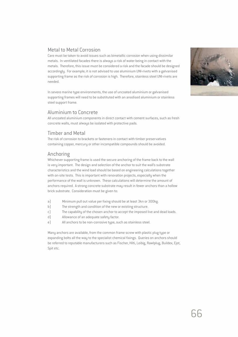
66
Metal to Metal CorrosionCare must be taken to avoid issues such as bimetallic corrosion when using dissimilar metals. In ventilated facades there is always a risk of water being in contact with the metals. Therefore, this issue must be considered a risk and the facade should be designed accordingly. For example; it is not advised to use aluminium UNI-rivets with a galvanised supporting frame as the risk of corrosion is high. Therefore, stainless steel UNI-rivets are needed.
In severe marine type environments, the use of uncoated aluminium or galvanised supporting frames will need to be substituted with an anodised aluminium or stainless steel support frame.
Aluminium to ConcreteAll uncoated aluminium components in direct contact with cement surfaces, such as fresh concrete walls, must always be isolated with protective pads.
Timber and Metal The risk of corrosion to brackets or fasteners in contact with timber preservatives containing copper, mercury or other incompatible compounds should be avoided.
AnchoringWhichever supporting frame is used the secure anchoring of the frame back to the wall is very important. The design and selection of the anchor to suit the wall’s substrate characteristics and the wind load should be based on engineering calculations together with on-site tests. This is important with renovation projects, especially when the performance of the wall is unknown. These calculations will determine the amount of anchors required. A strong concrete substrate may result in fewer anchors than a hollow brick substrate. Consideration must be given to:
a) Minimum pull out value per fixing should be at least 3kn or 300kg. b) The strength and condition of the new or existing structure.c) The capability of the chosen anchor to accept the imposed live and dead loads.d) Allowance of an adequate safety factor.e) All anchors to be non-corrosive type, such as stainless steel.
Many anchors are available, from the common frame screw with plastic plug type or expanding bolts all the way to the specialist chemical fixings. Queries on anchors should be referred to reputable manufacturers such as Fischer, Hilti, Leibig, Rawlplug, Buildex, Ejot, Spit etc.
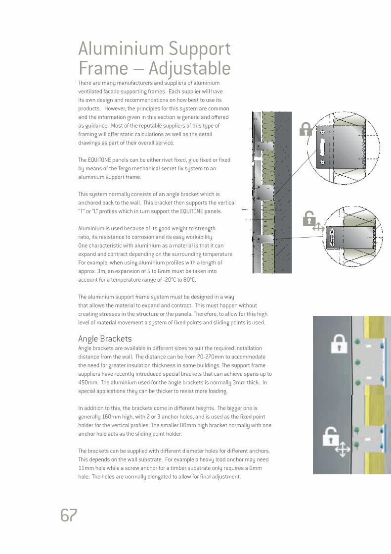
67
Aluminium Support Frame – AdjustableThere are many manufacturers and suppliers of aluminium ventilated facade supporting frames. Each supplier will have its own design and recommendations on how best to use its products. However, the principles for this system are common and the information given in this section is generic and offered as guidance. Most of the reputable suppliers of this type of framing will offer static calculations as well as the detail drawings as part of their overall service.
The EQUITONE panels can be either rivet fixed, glue fixed or fixed by means of the Tergo mechanical secret fix system to an aluminium support frame. This system normally consists of an angle bracket which is anchored back to the wall. This bracket then supports the vertical “T” or “L” profiles which in turn support the EQUITONE panels.
Aluminium is used because of its good weight to strength ratio, its resistance to corrosion and its easy workability. One characteristic with aluminium as a material is that it can expand and contract depending on the surrounding temperature. For example, when using aluminium profiles with a length of approx. 3m, an expansion of 5 to 6mm must be taken into account for a temperature range of -20°C to 80°C.
The aluminium support frame system must be designed in a way that allows the material to expand and contract. This must happen without creating stresses in the structure or the panels. Therefore, to allow for this high level of material movement a system of fixed points and sliding points is used. Angle BracketsAngle brackets are available in different sizes to suit the required installation distance from the wall. The distance can be from 70-270mm to accommodate the need for greater insulation thickness in some buildings. The support frame suppliers have recently introduced special brackets that can achieve spans up to 450mm. The aluminium used for the angle brackets is normally 3mm thick. In special applications they can be thicker to resist more loading.
In addition to this, the brackets come in different heights. The bigger one is generally 160mm high, with 2 or 3 anchor holes, and is used as the fixed point holder for the vertical profiles. The smaller 80mm high bracket normally with one anchor hole acts as the sliding point holder.
The brackets can be supplied with different diameter holes for different anchors. This depends on the wall substrate. For example a heavy load anchor may need 11mm hole while a screw anchor for a timber substrate only requires a 6mm hole. The holes are normally elongated to allow for final adjustment.
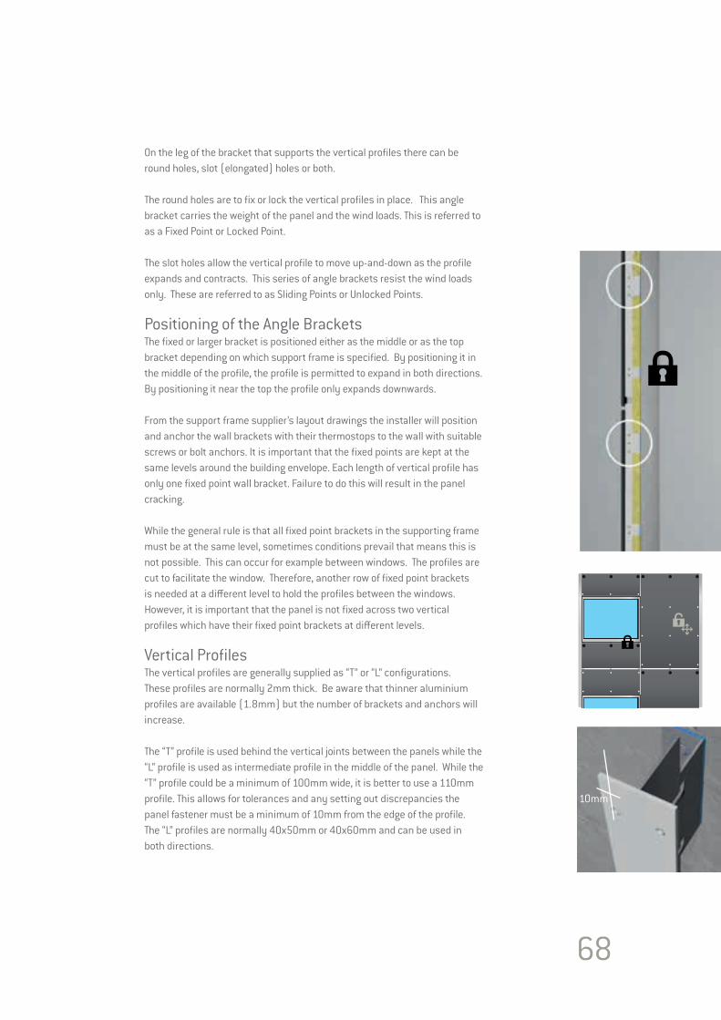
68
On the leg of the bracket that supports the vertical profiles there can be round holes, slot (elongated) holes or both.
The round holes are to fix or lock the vertical profiles in place. This angle bracket carries the weight of the panel and the wind loads. This is referred to as a Fixed Point or Locked Point.
The slot holes allow the vertical profile to move up-and-down as the profile expands and contracts. This series of angle brackets resist the wind loads only. These are referred to as Sliding Points or Unlocked Points.
Positioning of the Angle BracketsThe fixed or larger bracket is positioned either as the middle or as the top bracket depending on which support frame is specified. By positioning it in the middle of the profile, the profile is permitted to expand in both directions. By positioning it near the top the profile only expands downwards.
From the support frame supplier’s layout drawings the installer will position and anchor the wall brackets with their thermostops to the wall with suitable screws or bolt anchors. It is important that the fixed points are kept at the same levels around the building envelope. Each length of vertical profile has only one fixed point wall bracket. Failure to do this will result in the panel cracking.
While the general rule is that all fixed point brackets in the supporting frame must be at the same level, sometimes conditions prevail that means this is not possible. This can occur for example between windows. The profiles are cut to facilitate the window. Therefore, another row of fixed point brackets is needed at a different level to hold the profiles between the windows. However, it is important that the panel is not fixed across two vertical profiles which have their fixed point brackets at different levels.
Vertical ProfilesThe vertical profiles are generally supplied as “T” or “L” configurations. These profiles are normally 2mm thick. Be aware that thinner aluminium profiles are available (1.8mm) but the number of brackets and anchors will increase.
The “T” profile is used behind the vertical joints between the panels while the “L” profile is used as intermediate profile in the middle of the panel. While the “T” profile could be a minimum of 100mm wide, it is better to use a 110mm profile. This allows for tolerances and any setting out discrepancies the panel fastener must be a minimum of 10mm from the edge of the profile. The “L” profiles are normally 40x50mm or 40x60mm and can be used in both directions.
10mm
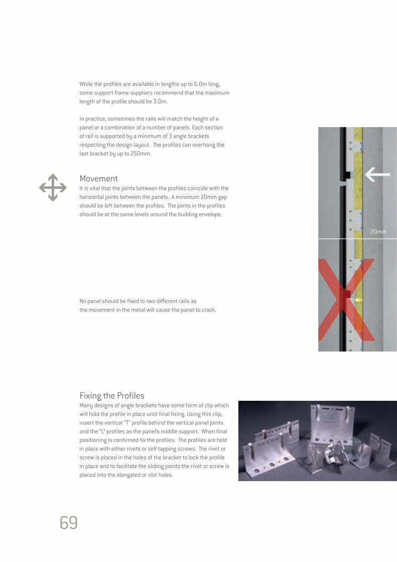
69
While the profiles are available in lengths up to 6.0m long, some support frame suppliers recommend that the maximum length of the profile should be 3.0m.
In practice, sometimes the rails will match the height of a panel or a combination of a number of panels. Each section of rail is supported by a minimum of 3 angle brackets respecting the design layout. The profiles can overhang the last bracket by up to 250mm.
Movement It is vital that the joints between the profiles coincide with the horizontal joints between the panels. A minimum 20mm gap should be left between the profiles. The joints in the profiles should be at the same levels around the building envelope.
No panel should be fixed to two different rails as the movement in the metal will cause the panel to crack.
Fixing the ProfilesMany designs of angle brackets have some form of clip which will hold the profile in place until final fixing. Using this clip, insert the vertical “T” profile behind the vertical panel joints and the “L” profiles as the panel’s middle support. When final positioning is confirmed fix the profiles. The profiles are held in place with either rivets or self tapping screws. The rivet or screw is placed in the holes of the bracket to lock the profile in place and to facilitate the sliding points the rivet or screw is placed into the elongated or slot holes.
20mm
70
Other Aluminium SystemsFloor-to-FloorThis system consists of heavy U-shaped brackets which are fixed into the ends of the concrete floor slabs. Between these brackets, box section or U-shaped profiles normally of 3-4mm thickness span. The same principles of fixed and sliding points for allowing movement is required. The brackets should also be backed with suitable “thermostops”. A separate internal wall is needed.
Systems to reduce the effect of thermal bridgesThis system uses the principle of reducing the amount of metal-to-metal contact. The metal in contact with the thermostop is minimised. The bracket and its hanger piece are also separated with heavy duty plastic breakers.
Horizontal SystemsThis system is used where the anchoring opportunities in the wall is limited. By first fixing a bracket to support a horizontal profile allows the vertical panel profiles to be positioned to match the panel design. These systems adopt the same principles of fixed and sliding points for movement. The brackets should also be backed with suitable “thermostops”.
UK suppliers of Aluminium SystemsHiltiNVELOPE
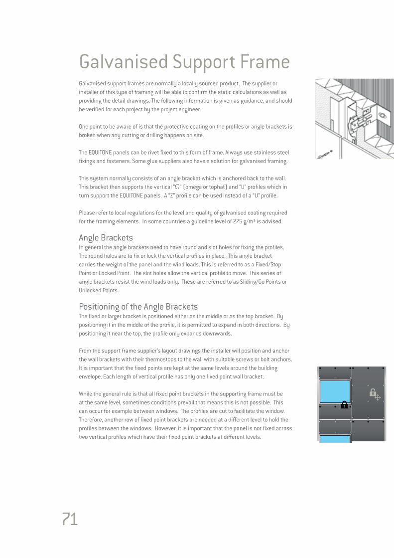
71
Galvanised Support FrameGalvanised support frames are normally a locally sourced product. The supplier or installer of this type of framing will be able to confirm the static calculations as well as providing the detail drawings. The following information is given as guidance, and should be verified for each project by the project engineer.
One point to be aware of is that the protective coating on the profiles or angle brackets is broken when any cutting or drilling happens on site.
The EQUITONE panels can be rivet fixed to this form of frame. Always use stainless steel fixings and fasteners. Some glue suppliers also have a solution for galvanised framing.
This system normally consists of an angle bracket which is anchored back to the wall. This bracket then supports the vertical “Ω” (omega or tophat) and “U” profiles which in turn support the EQUITONE panels. A “Z” profile can be used instead of a “U” profile.
Please refer to local regulations for the level and quality of galvanised coating required for the framing elements. In some countries a guideline level of 275 g/m² is advised.
Angle BracketsIn general the angle brackets need to have round and slot holes for fixing the profiles. The round holes are to fix or lock the vertical profiles in place. This angle bracket carries the weight of the panel and the wind loads. This is referred to as a Fixed/Stop Point or Locked Point. The slot holes allow the vertical profile to move. This series of angle brackets resist the wind loads only. These are referred to as Sliding/Go Points or Unlocked Points.
Positioning of the Angle BracketsThe fixed or larger bracket is positioned either as the middle or as the top bracket. By positioning it in the middle of the profile, it is permitted to expand in both directions. By positioning it near the top, the profile only expands downwards.
From the support frame supplier’s layout drawings the installer will position and anchor the wall brackets with their thermostops to the wall with suitable screws or bolt anchors. It is important that the fixed points are kept at the same levels around the building envelope. Each length of vertical profile has only one fixed point wall bracket.
While the general rule is that all fixed point brackets in the supporting frame must be at the same level, sometimes conditions prevail that means this is not possible. This can occur for example between windows. The profiles are cut to facilitate the window. Therefore, another row of fixed point brackets are needed at a different level to hold the profiles between the windows. However, it is important that the panel is not fixed across two vertical profiles which have their fixed point brackets at different levels.

72
25/4
0
40Vertical ProfilesThese “Ω” and “Z” profiles are normally 1.5mm thick. The “Ω” profile is used behind the vertical joints between the panels while the “Z” profile is used as intermediate profiles in the middle of the panel. The “Ω” profile is a minimum of 100mm wide. However, it is better to be 110mm or 120mm wide. This allows for tolerance and any setting out discrepancies. The “Z” profiles are normally 40x40mm.
Each section of rail is supported by a minimum of 3 brackets. The profiles can overhang the last bracket by 250mm.
Movement The thermal expansion of galvanised steel is not the same as aluminium. It is accepted that galvanised steel has a thermal movement less than half that experienced by aluminium. For example a profile less than 4.0m long may not need any allowance for movement.
Therefore, it maybe possible to simply use only fixed point brackets. However, the principle of fixed and sliding points is a good one and where possible is recommended for all metal supporting frames. This is especially relevant in climates that experience extremes levels of and variations in temperatures.
The joints between the profiles must also coincide with the horizontal joints between the panels. A minimum 20mm gap should be left between the profiles. The joints in the profiles should be at the same levels around the building envelope. No panel should be fixed to two different profiles as the movement in the metal may cause the panel to crack. Different support frame arrangements are possible which are shown here, but note that the panel is never fixed to two separate profiles. Fixing the ProfilesWhen final positioning is confirmed fix the profiles. The profiles are held in place with either stainless steel rivets or self tapping screws. The rivet or screw is placed in the holes of the bracket to lock the profile in place and to facilitate the sliding/go points, the rivet or screw is placed into the elongated or slot holes.
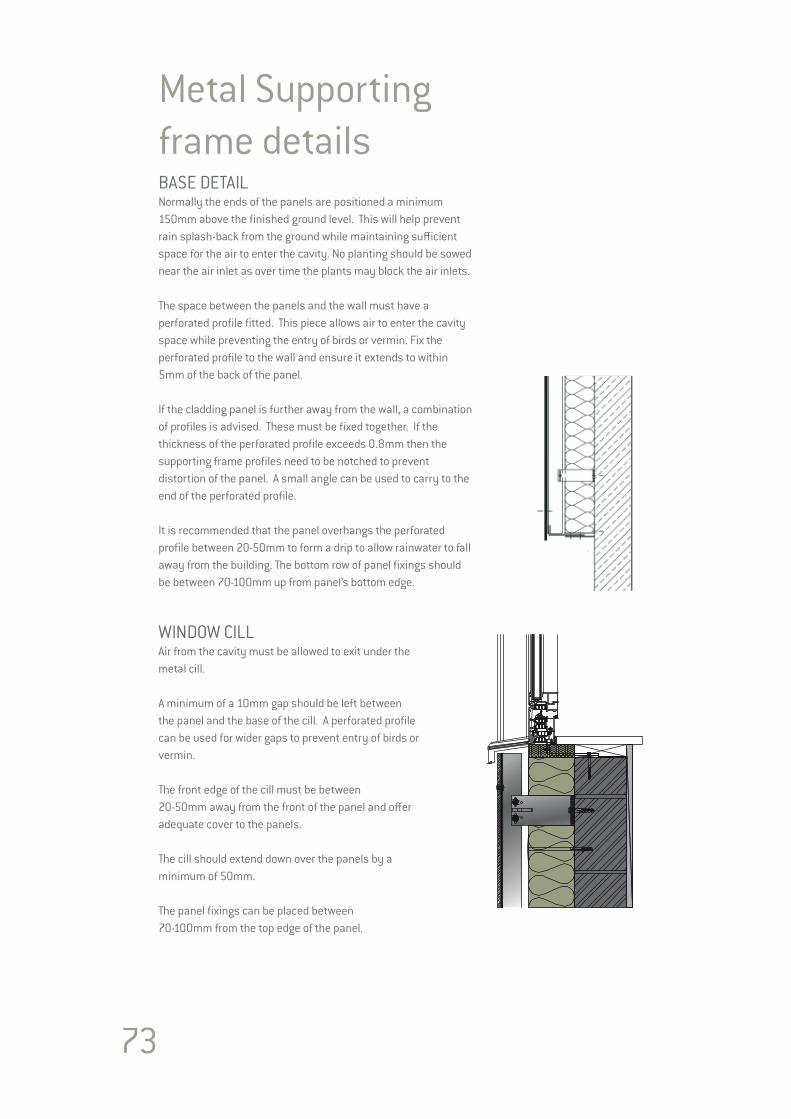
73
Metal Supporting frame detailsBASE DETAILNormally the ends of the panels are positioned a minimum 150mm above the finished ground level. This will help prevent rain splash-back from the ground while maintaining sufficient space for the air to enter the cavity. No planting should be sowed near the air inlet as over time the plants may block the air inlets.
The space between the panels and the wall must have a perforated profile fitted. This piece allows air to enter the cavity space while preventing the entry of birds or vermin. Fix the perforated profile to the wall and ensure it extends to within 5mm of the back of the panel.
If the cladding panel is further away from the wall, a combination of profiles is advised. These must be fixed together. If the thickness of the perforated profile exceeds 0.8mm then the supporting frame profiles need to be notched to prevent distortion of the panel. A small angle can be used to carry to the end of the perforated profile.
It is recommended that the panel overhangs the perforated profile between 20-50mm to form a drip to allow rainwater to fall away from the building. The bottom row of panel fixings should be between 70-100mm up from panel’s bottom edge.
WINDOW CILL Air from the cavity must be allowed to exit under the metal cill.
A minimum of a 10mm gap should be left between the panel and the base of the cill. A perforated profile can be used for wider gaps to prevent entry of birds or vermin.
The front edge of the cill must be between 20-50mm away from the front of the panel and offer adequate cover to the panels.
The cill should extend down over the panels by a minimum of 50mm.
The panel fixings can be placed between 70-100mm from the top edge of the panel.
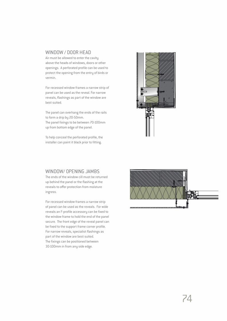
74
WINDOW / DOOR HEADAir must be allowed to enter the cavity above the heads of windows, doors or other openings. A perforated profile can be used to protect the opening from the entry of birds or vermin.
For recessed window frames a narrow strip of panel can be used as the reveal. For narrow reveals, flashings as part of the window are best suited.
The panel can overhang the ends of the rails to form a drip by 20-50mm. The panel fixings to be between 70-100mm up from bottom edge of the panel.
To help conceal the perforated profile, the installer can paint it black prior to fitting.
WINDOW/ OPENING JAMBSThe ends of the window cill must be returned up behind the panel or the flashing at the reveals to offer protection from moisture ingress.
For recessed window frames a narrow strip of panel can be used as the reveals. For wide reveals an F-profile accessory can be fixed to the window frame to hold the end of the panel secure. The front edge of the reveal panel can be fixed to the support frame corner profile.For narrow reveals, specialist flashings as part of the window are best suited.The fixings can be positioned between 30-100mm in from any side edge.

75
EXTERNAL CORNERExternal corners may be left as open joints or fitted with a proprietary trim profile.
Normally for open joints a 60x60mm angle profile is used to support the panel edges. Where this angle can not be fixed back to the wall, provide panel support within 350mm of the corner. Joints in the corner profiles must coincide with the support frame expansion joints.
Any trim profile must be less than 0.8mm thick to prevent distortion of panel. Trim profiles need to be fully supported on angle profiles.
Some support frame suppliers have special structural corner profiles in their range.
INTERNAL CORNERInternal corners may be left as open joints or fitted with a proprietary trim profile.
A 60x60mm angle profile can be used to support the panel edges. As it is easier to fix the main support frame to an internal corner, the open joint does not always need an angle bracket.
Any trim profile must be less than 0.8mm thick to prevent distortion of panel. Trim profiles need to be fully supported on angle profiles.
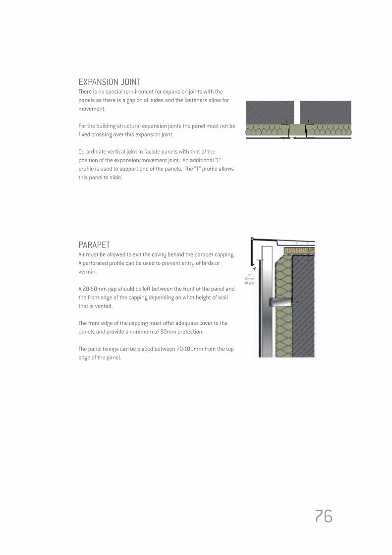
76
EXPANSION JOINTThere is no special requirement for expansion joints with the panels as there is a gap on all sides and the fasteners allow for movement.
For the building structural expansion joints the panel must not be fixed crossing over this expansion joint.
Co-ordinate vertical joint in facade panels with that of the position of the expansion/movement joint. An additional “L” profile is used to support one of the panels. The “T” profile allows this panel to slide.
PARAPETAir must be allowed to exit the cavity behind the parapet capping. A perforated profile can be used to prevent entry of birds or vermin.
A 20-50mm gap should be left between the front of the panel and the front edge of the capping depending on what height of wall that is vented.
The front edge of the capping must offer adequate cover to the panels and provide a minimum of 50mm protection.
The panel fixings can be placed between 70-100mm from the top edge of the panel.
min.10mmair gap
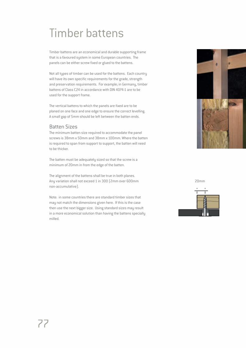
77
Timber battensTimber battens are an economical and durable supporting frame that is a favoured system in some European countries. The panels can be either screw fixed or glued to the battens.
Not all types of timber can be used for the battens. Each country will have its own specific requirements for the grade, strength and preservation requirements. For example; in Germany, timber battens of Class C24 in accordance with DIN 4074-1 are to be used for the support frame.
The vertical battens to which the panels are fixed are to be planed on one face and one edge to ensure the correct levelling. A small gap of 5mm should be left between the batten ends.
Batten SizesThe minimum batten size required to accommodate the panel screws is 38mm x 50mm and 38mm x 100mm. Where the batten is required to span from support to support, the batten will need to be thicker.
The batten must be adequately sized so that the screw is a minimum of 20mm in from the edge of the batten.
The alignment of the battens shall be true in both planes. Any variation shall not exceed 1 in 300 (2mm over 600mm non-accumulative).
Note: in some countries there are standard timber sizes that may not match the dimensions given here. If this is the case then use the next bigger size. Using standard sizes may result in a more economical solution than having the battens specially milled.
20mm
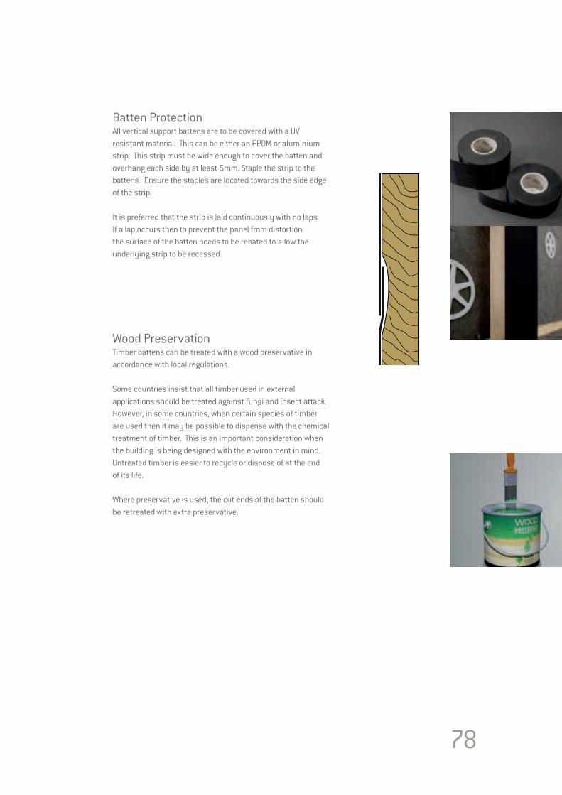
78
Batten ProtectionAll vertical support battens are to be covered with a UV resistant material. This can be either an EPDM or aluminium strip. This strip must be wide enough to cover the batten and overhang each side by at least 5mm. Staple the strip to the battens. Ensure the staples are located towards the side edge of the strip.
It is preferred that the strip is laid continuously with no laps. If a lap occurs then to prevent the panel from distortion the surface of the batten needs to be rebated to allow the underlying strip to be recessed.
Wood PreservationTimber battens can be treated with a wood preservative in accordance with local regulations.
Some countries insist that all timber used in external applications should be treated against fungi and insect attack. However, in some countries, when certain species of timber are used then it may be possible to dispense with the chemical treatment of timber. This is an important consideration when the building is being designed with the environment in mind. Untreated timber is easier to recycle or dispose of at the end of its life.
Where preservative is used, the cut ends of the batten should be retreated with extra preservative.
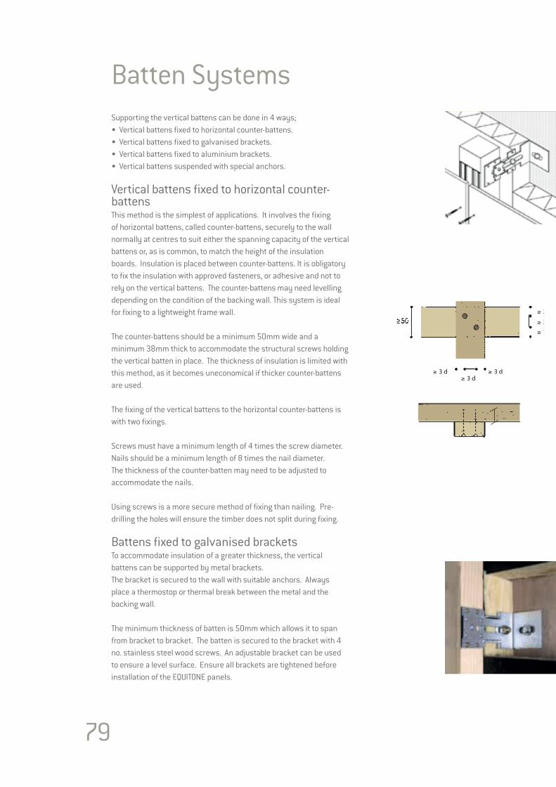
79
Batten SystemsSupporting the vertical battens can be done in 4 ways;• Vertical battens fixed to horizontal counter-battens.• Vertical battens fixed to galvanised brackets.• Vertical battens fixed to aluminium brackets.• Vertical battens suspended with special anchors.
Vertical battens fixed to horizontal counter-battensThis method is the simplest of applications. It involves the fixing of horizontal battens, called counter-battens, securely to the wall normally at centres to suit either the spanning capacity of the vertical battens or, as is common, to match the height of the insulation boards. Insulation is placed between counter-battens. It is obligatory to fix the insulation with approved fasteners, or adhesive and not to rely on the vertical battens. The counter-battens may need levelling depending on the condition of the backing wall. This system is ideal for fixing to a lightweight frame wall.
The counter-battens should be a minimum 50mm wide and a minimum 38mm thick to accommodate the structural screws holding the vertical batten in place. The thickness of insulation is limited with this method, as it becomes uneconomical if thicker counter-battens are used.
The fixing of the vertical battens to the horizontal counter-battens is with two fixings.
Screws must have a minimum length of 4 times the screw diameter.Nails should be a minimum length of 8 times the nail diameter. The thickness of the counter-batten may need to be adjusted to accommodate the nails.
Using screws is a more secure method of fixing than nailing. Pre-drilling the holes will ensure the timber does not split during fixing.
Battens fixed to galvanised bracketsTo accommodate insulation of a greater thickness, the vertical battens can be supported by metal brackets. The bracket is secured to the wall with suitable anchors. Always place a thermostop or thermal break between the metal and the backing wall. The minimum thickness of batten is 50mm which allows it to span from bracket to bracket. The batten is secured to the bracket with 4 no. stainless steel wood screws. An adjustable bracket can be used to ensure a level surface. Ensure all brackets are tightened before installation of the EQUITONE panels.
≥ 3 d
≥ 3 d
≥ 3 d≥ 3 d
≥ 3 d
≥ 7 d
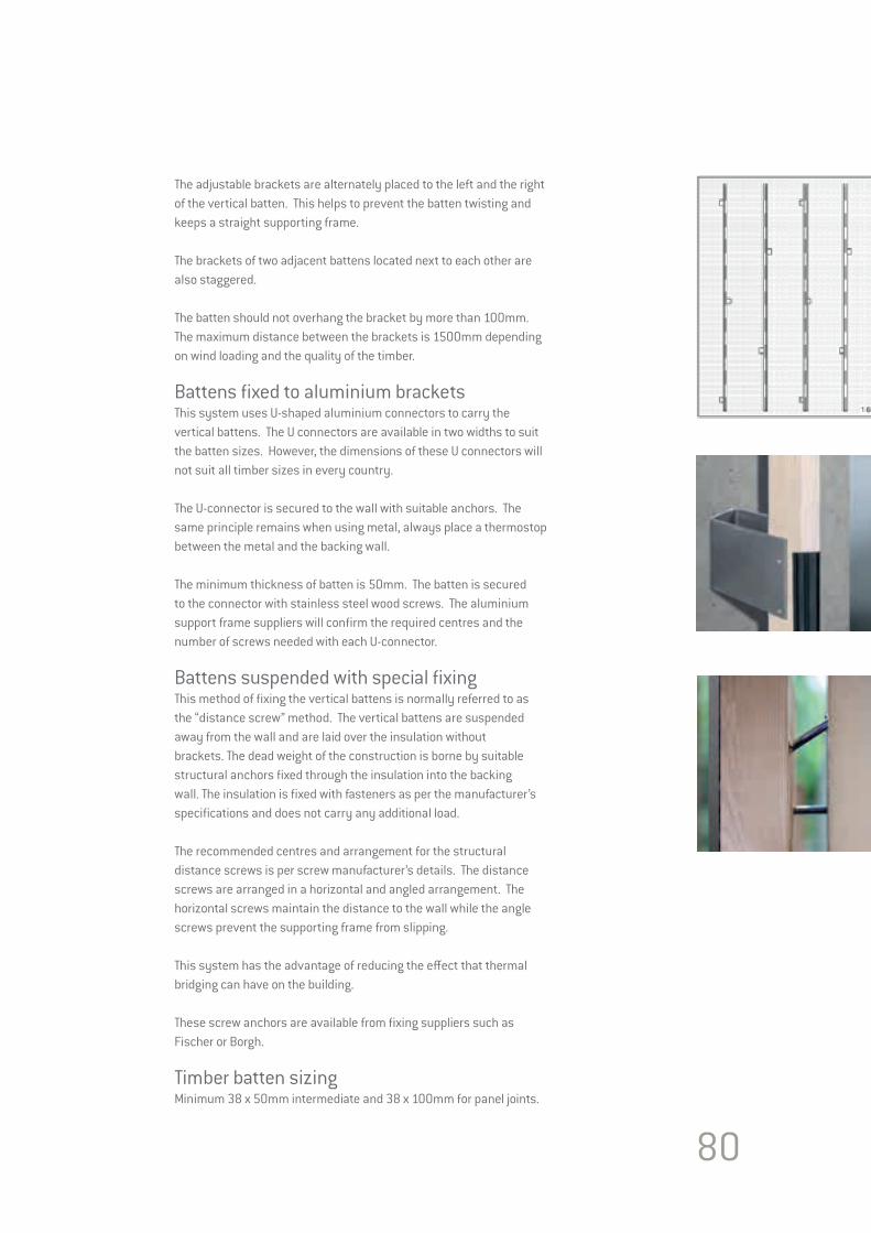
80
The adjustable brackets are alternately placed to the left and the right of the vertical batten. This helps to prevent the batten twisting and keeps a straight supporting frame.
The brackets of two adjacent battens located next to each other are also staggered.
The batten should not overhang the bracket by more than 100mm.The maximum distance between the brackets is 1500mm depending on wind loading and the quality of the timber.
Battens fixed to aluminium bracketsThis system uses U-shaped aluminium connectors to carry the vertical battens. The U connectors are available in two widths to suit the batten sizes. However, the dimensions of these U connectors will not suit all timber sizes in every country.
The U-connector is secured to the wall with suitable anchors. The same principle remains when using metal, always place a thermostop between the metal and the backing wall. The minimum thickness of batten is 50mm. The batten is secured to the connector with stainless steel wood screws. The aluminium support frame suppliers will confirm the required centres and the number of screws needed with each U-connector.
Battens suspended with special fixingThis method of fixing the vertical battens is normally referred to as the “distance screw” method. The vertical battens are suspended away from the wall and are laid over the insulation without brackets. The dead weight of the construction is borne by suitable structural anchors fixed through the insulation into the backing wall. The insulation is fixed with fasteners as per the manufacturer’s specifications and does not carry any additional load.
The recommended centres and arrangement for the structural distance screws is per screw manufacturer’s details. The distance screws are arranged in a horizontal and angled arrangement. The horizontal screws maintain the distance to the wall while the angle screws prevent the supporting frame from slipping.
This system has the advantage of reducing the effect that thermal bridging can have on the building.
These screw anchors are available from fixing suppliers such as Fischer or Borgh.
Timber batten sizingMinimum 38 x 50mm intermediate and 38 x 100mm for panel joints.

81
Timber DetailsBASE DETAILNormally the ends of the panels are positioned a minimum 150mm above the finished ground level (minimum 300mm for EQUITONE [materia]). This will help prevent rain splash-back from the ground while maintaining sufficient space for the air to enter the cavity. No planting should be sowed near the air inlet as over time the plants may block the air inlets.
The space between the panels and the wall must have a perforated profile fitted. This profile allows air to enter the cavity space while preventing the entry of birds or vermin. Fix the profile to the wall and ensure it extends to within 5mm of the back of the panel.
If the cladding panel is further away from the wall, a combination of perforated profiles is advised. These must be fixed together.
It is recommended that the panel overhangs the perforated profile between 20-50mm to form a drip to allow rain water to fall away from the building. The bottom row of panel fixings should be between 70-100mm up from the panel’s bottom edge.
WINDOW CILL Air from the cavity must be allowed to exit under the metal cill. A minimum of a 10mm gap should be left between the panel and the base of the cill. A perforated profile can be used for wider gaps to prevent entry of birds or vermin.
The front edge of the cill must be between 20-50mm away from the front of the panel and offer adequate cover to the panels. The cill should extend down over the panels by a minimum of 50mm.
WINDOW / OPENING HEADAir must be allowed to enter the cavity over the heads of openings. A perforated profile can be used to allow air circulation and prevent entry of birds or vermin.
For recessed window frames a narrow strip of panel can be used as the reveals. For narrow reveals, flashings as part of the window are best suited. The panel can overhang the ends of the battens to form a drip by 20-50mm. The panel fixings to be between 70-100mm up from bottom edge of the panel. To help conceal the perforated profile, the installer can paint it black prior to fitting.
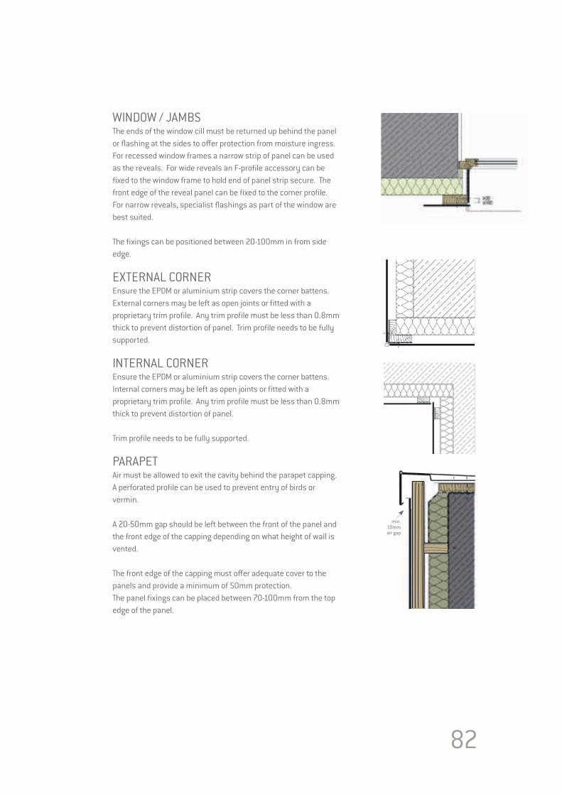
82
WINDOW / JAMBSThe ends of the window cill must be returned up behind the panel or flashing at the sides to offer protection from moisture ingress.For recessed window frames a narrow strip of panel can be used as the reveals. For wide reveals an F-profile accessory can be fixed to the window frame to hold end of panel strip secure. The front edge of the reveal panel can be fixed to the corner profile.For narrow reveals, specialist flashings as part of the window are best suited.
The fixings can be positioned between 20-100mm in from side edge.
EXTERNAL CORNEREnsure the EPDM or aluminium strip covers the corner battens. External corners may be left as open joints or fitted with a proprietary trim profile. Any trim profile must be less than 0.8mm thick to prevent distortion of panel. Trim profile needs to be fully supported.
INTERNAL CORNEREnsure the EPDM or aluminium strip covers the corner battens. Internal corners may be left as open joints or fitted with a proprietary trim profile. Any trim profile must be less than 0.8mm thick to prevent distortion of panel.
Trim profile needs to be fully supported.
PARAPETAir must be allowed to exit the cavity behind the parapet capping. A perforated profile can be used to prevent entry of birds or vermin.
A 20-50mm gap should be left between the front of the panel and the front edge of the capping depending on what height of wall is vented.
The front edge of the capping must offer adequate cover to the panels and provide a minimum of 50mm protection.The panel fixings can be placed between 70-100mm from the top edge of the panel.
min.10mmair gap
83
84
DESIGN CONSIDERATIONS Section 6
DESIGN CONSIDERATIONS
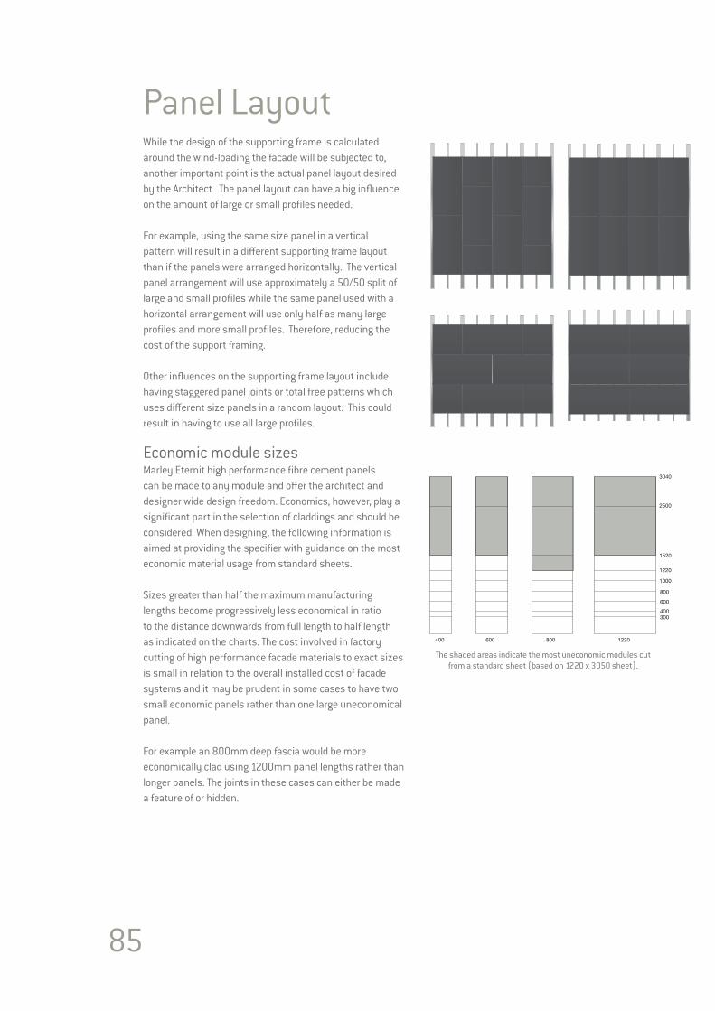
85
Panel LayoutWhile the design of the supporting frame is calculated around the wind-loading the facade will be subjected to, another important point is the actual panel layout desired by the Architect. The panel layout can have a big influence on the amount of large or small profiles needed.
For example, using the same size panel in a vertical pattern will result in a different supporting frame layout than if the panels were arranged horizontally. The vertical panel arrangement will use approximately a 50/50 split of large and small profiles while the same panel used with a horizontal arrangement will use only half as many large profiles and more small profiles. Therefore, reducing the cost of the support framing.
Other influences on the supporting frame layout include having staggered panel joints or total free patterns which uses different size panels in a random layout. This could result in having to use all large profiles. Economic module sizesMarley Eternit high performance fibre cement panels can be made to any module and offer the architect and designer wide design freedom. Economics, however, play a significant part in the selection of claddings and should be considered. When designing, the following information is aimed at providing the specifier with guidance on the most economic material usage from standard sheets.
Sizes greater than half the maximum manufacturing lengths become progressively less economical in ratio to the distance downwards from full length to half length as indicated on the charts. The cost involved in factory cutting of high performance facade materials to exact sizes is small in relation to the overall installed cost of facade systems and it may be prudent in some cases to have two small economic panels rather than one large uneconomical panel. For example an 800mm deep fascia would be more economically clad using 1200mm panel lengths rather than longer panels. The joints in these cases can either be made a feature of or hidden.
3040
2500
1520
1220
1000
800
600
400300
1220800600400
The shaded areas indicate the most uneconomic modules cut from a standard sheet (based on 1220 x 3050 sheet).
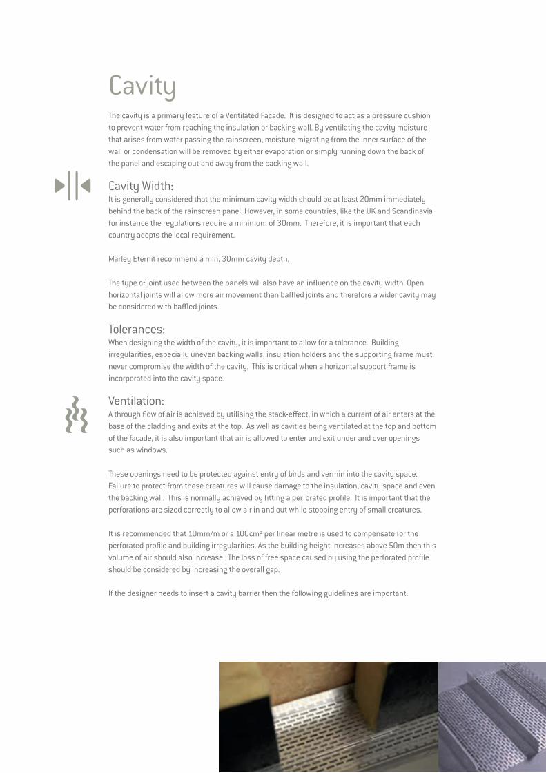
CavityThe cavity is a primary feature of a Ventilated Facade. It is designed to act as a pressure cushion to prevent water from reaching the insulation or backing wall. By ventilating the cavity moisture that arises from water passing the rainscreen, moisture migrating from the inner surface of the wall or condensation will be removed by either evaporation or simply running down the back of the panel and escaping out and away from the backing wall.
Cavity Width:It is generally considered that the minimum cavity width should be at least 20mm immediately behind the back of the rainscreen panel. However, in some countries, like the UK and Scandinavia for instance the regulations require a minimum of 30mm. Therefore, it is important that each country adopts the local requirement.
Marley Eternit recommend a min. 30mm cavity depth.
The type of joint used between the panels will also have an influence on the cavity width. Open horizontal joints will allow more air movement than baffled joints and therefore a wider cavity may be considered with baffled joints.
Tolerances:When designing the width of the cavity, it is important to allow for a tolerance. Building irregularities, especially uneven backing walls, insulation holders and the supporting frame must never compromise the width of the cavity. This is critical when a horizontal support frame is incorporated into the cavity space. Ventilation:A through flow of air is achieved by utilising the stack-effect, in which a current of air enters at the base of the cladding and exits at the top. As well as cavities being ventilated at the top and bottom of the facade, it is also important that air is allowed to enter and exit under and over openings such as windows.
These openings need to be protected against entry of birds and vermin into the cavity space. Failure to protect from these creatures will cause damage to the insulation, cavity space and even the backing wall. This is normally achieved by fitting a perforated profile. It is important that the perforations are sized correctly to allow air in and out while stopping entry of small creatures.
It is recommended that 10mm/m or a 100cm² per linear metre is used to compensate for the perforated profile and building irregularities. As the building height increases above 50m then this volume of air should also increase. The loss of free space caused by using the perforated profile should be considered by increasing the overall gap.
If the designer needs to insert a cavity barrier then the following guidelines are important:

87
JointsIt is a feature of a ventilated facade that the joints do not need to be sealed because the water penetration is managed by a combination of the cavity and the air tightness of the backing wall. Normally three types of joints are used between the panels.
• Open joints in which there is a clear open gap between the edges of adjoining panels.
• Baffled joints where some component is used to block the direct line through the joint, while not sealing the joint.
• Overlap joint in which one panel overlaps the adjacent panel. Shiplap is an example of this.
Sealed joints where a gasket or wet applied sealant is used to make the joint water-tight and air-tight is never specified with EQUITONE panels.
Joint WidthMany years of practice have shown that the optimum width of the joints between large panels is 10mm. Aesthetically a 10mm joint is the best. 10mm also offers the installer a level of tolerance when fitting the panel. The minimum permissible joint is 8mm while the maximum would be 12mm.
Vertical JointsVertical joints are mostly backed with a continuous profile.
When a metal supporting frame is used, the grey or silver colour can be prominent especially when used with dark coloured panels. This could be an unappealing feature. To eliminate this, the best solution is to use black coated metal profiles, such as anodised aluminium. Alternatively, the visible areas can be painted on site prior to fitting the panels. Another solution is the use a good quality external black tape. Make sure the profiles are prepped correctly before painting or taping as new metal profiles can have an oily surface. Note, the painting or taping of the profiles on site will not endure as long as the anodised metal profiles.
For timber supporting frames the batten is faced with a strip of EPDM or black aluminium foil which makes the open joint visually more pleasing. This strip also gives added protection to the battens.
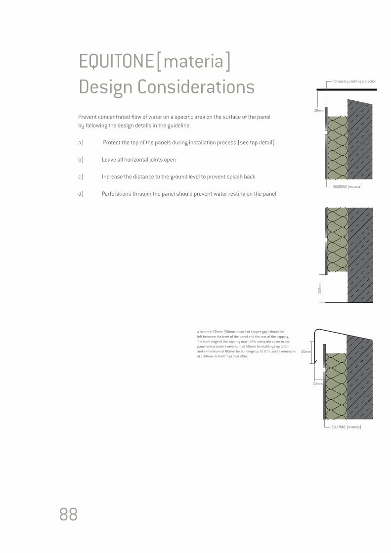
88
Prevent concentrated flow of water on a specific area on the surface of the panelby following the design details in the guideline.
a) Protect the top of the panels during installation process (see top detail)
b) Leave all horizontal joints open
c) Increase the distance to the ground level to prevent splash back
d) Perforations through the panel should prevent water resting on the panel
EQUITONE[materia] Design Considerations
20mm
EQUITONE [materia]
Temporary cladding protection
300m
m
20mm
50mm
EQUITONE [materia]
A minimal 20mm [50mm in case of copper gap] should be left between the front of the panel and the rear of the capping. The front edge of the capping must o�er adequate cover to the panel and provide a minimum of 50mm for buildings up to 8m and a minimum of 80mm for buildings up to 20m, and a minimum of 100mm for buildings over 20m.
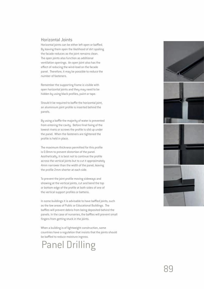
89
Horizontal JointsHorizontal joints can be either left open or baffled. By leaving them open the likelihood of dirt spoiling the facade reduces as the joint remains clean. The open joints also function as additional ventilation openings. An open joint also has the effect of reducing the wind-load on the facade panel. Therefore, it may be possible to reduce the number of fasteners.
Remember the supporting frame is visible with open horizontal joints and they may need to be hidden by using black profiles, paint or tape.
Should it be required to baffle the horizontal joint, an aluminium joint profile is inserted behind the panels.
By using a baffle the majority of water is prevented from entering the cavity. Before final fixing of the lowest rivets or screws the profile is slid up under the panel. When the fasteners are tightened the profile is held in place.
The maximum thickness permitted for this profile is 0.8mm to prevent distortion of the panel. Aesthetically, it is best not to continue the profile across the vertical joints but to cut it approximately 4mm narrower than the width of the panel, leaving the profile 2mm shorter at each side.
To prevent the joint profile moving sideways and showing at the vertical joints, cut and bend the top or bottom edge of the profile at both sides of one of the vertical support profiles or battens.
In some buildings it is advisable to have baffled joints, such as the low areas of Public or Educational Buildings. The baffles will prevent debris from being deposited behind the panels. In the case of nurseries, the baffles will prevent small fingers from getting stuck in the joints.
When a building is of lightweight construction, some countries have a regulation that insists that the joints should be baffled to reduce moisture ingress.
Panel Drilling

90
FireIn most European countries, there are different fire regulations related to the height of the building or its proximity to the site boundary or adjoining buildings. Firstly, it is important to note the differences between reaction-to-fire and fire resistance.
Reaction to FireReaction-to-fire focuses on the behaviour of the materials during the development of a fire. This allows a designer to choose a material suitable for an application. The European standard EN 13501-1: Reaction to Fire provides a number of performance criteria to measure the fire characteristics of building materials. These cover spread of flame and contribution to fire as well as the generation of smoke and the production of burning droplets.
The designations are:Spread of flameA1, A2, B, C, D, E, F. A1 and A2,s1,d0 are both classed as non-combustible, while at the other end of the scale an F rating is easily flammable.Smokes1, s2, s3.s1 refers to a material generating little or no smoke. Where as, S2 rated materials generate medium smoke and S3 produces heavy smoke.Burning dropletsd0, d1, d2.d0 rated materials produce no droplets within 600 seconds. While d1 rated materials will produce droplets within 600 seconds but do not burn for more than 10 seconds. d2 material are all those which do not fall in d0 or d1 designation.EQUITONE panels achieve a A2,s1,d0 classification.
Fire ResistanceFire resistance is based on EN 13501-2 and encompass the whole structural element and not just the facade material. This may consist of the complete facade wall from the outer rainscreen panel to the internal wall finish. The entire element should resist the impact of fire on its structural ability for as long as possible.
Local requirementsIn addition to the European Standards there may also be some specific local requirements needed. For example in Denmark a local K10 test is needed.
Height of BuildingThere seems to be a similarity in most countries that buildings over 18-20 metres high require that the facade panels has a higher rating, A1 or A2-s1, d0 in accordance with EN 13501-1. This is an important factor due to the effectiveness of fire fighting equipment. EQUITONE fibre cement panels have excellent fire resisting performance, achieving A2-s1, d0 rating and have unrestricted use on buildings, no matter what height.
Proximity to other buildings and site boundarySome countries regulations also restrict what materials can be used on facades which are near other buildings or the site boundary. This is intended to prevent a fire from one building jumping to the next. Restrictions on the amount and size of openings such as windows are also limited by the regulation.
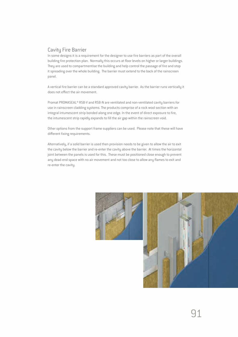
91
Cavity Fire BarrierIn some designs it is a requirement for the designer to use fire barriers as part of the overall building fire protection plan. Normally this occurs at floor levels on higher or larger buildings. They are used to compartmentise the building and help control the passage of fire and stop it spreading over the whole building. The barrier must extend to the back of the rainscreen panel.
A vertical fire barrier can be a standard approved cavity barrier. As the barrier runs vertically it does not effect the air movement.
Promat PROMASEAL® RSB-V and RSB-N are ventilated and non-ventilated cavity barriers for use in rainscreen cladding systems. The products comprise of a rock wool section with an integral intumescent strip bonded along one edge. In the event of direct exposure to fire, the intumescent strip rapidly expands to fill the air gap within the rainscreen void.
Other options from the support frame suppliers can be used. Please note that these will have different fixing requirements.
Alternatively, if a solid barrier is used then provision needs to be given to allow the air to exit the cavity below the barrier and re-enter the cavity above the barrier. At times the horizontal joint between the panels is used for this. These must be positioned close enough to prevent any dead-end space with no air movement and not too close to allow any flames to exit and re-enter the cavity.

92
WallsStructural WallThe backing wall is critical to the performance of a ventilated facade system. If air movement through the backing wall is too great then the risk of water penetration is increased. Air leakage through the backing wall also presents a path for energy loss, and so must be limited.
It is important for the designer to consider what fixing will be used to secure the panel’s support frame. Some of the wind loading is transmitted back to the backing wall and this should be allowed for.
Masonry WallDepending on what is the predominant local material, masonry walls can consist of clay, lightweight (clinker) block, concrete blocks or indeed a solid cast-in-situ or precast concrete panels. The wall can either be a full self-supporting load bearing structure or an infill between floor beams and columns.
This type of wall may be existing or a new build. For renovation projects it is advisable that the project engineer checks all masonry walls to ascertain whether the wall is sound and can support the added load. Many fixing suppliers will perform a pull-out test on a wall to confirm its capabilities.
Lightweight WallA lightweight structure of metal or timber stud is another form of backing wall. This is commonly used as an infill wall between concrete floors. This type of wall may need special fixings to hold the frame within the main building structure. It is also possible to construct complete structures.
The face of the frame requires a panel such as Duripanel or a fibre cement building board to act as a “wind-shield”. The board may be required to offer some racking resistance or fire resistance. This wind-shield must be air tight. This can be achieved by using the correct wind-shield board and tapping the joints with suitable long lasting tape.
With this type of construction, consideration needs to be given to the best way to fix the EQUITONE’s support framing. By fixing a horizontal rail or batten over the wind-shield and into the vertical studs the designer has the freedom to place the EQUITONE panel vertical support profiles anywhere. Therefore, the EQUITONE panel support profiles do not have to coincide with the structure studs. The space formed by these horizontal rails or battens can be utilised with the insertion of extra insulation.
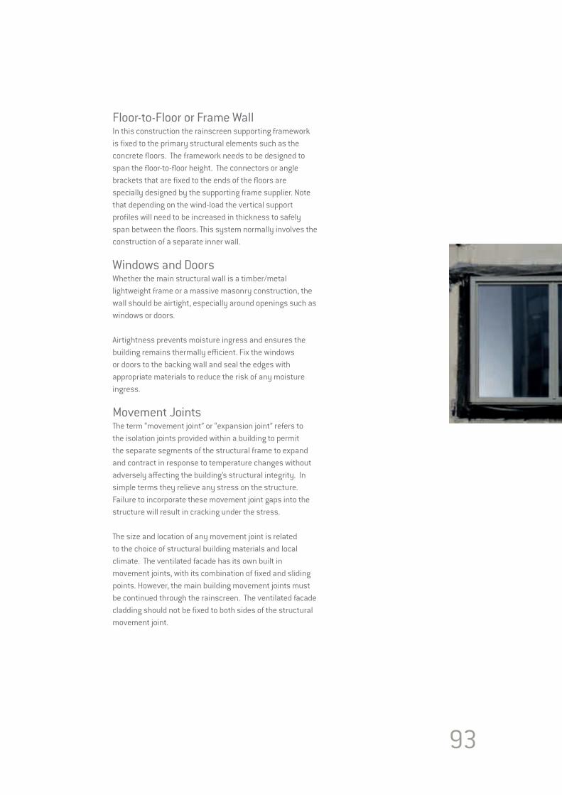
93
Floor-to-Floor or Frame WallIn this construction the rainscreen supporting framework is fixed to the primary structural elements such as the concrete floors. The framework needs to be designed to span the floor-to-floor height. The connectors or angle brackets that are fixed to the ends of the floors are specially designed by the supporting frame supplier. Note that depending on the wind-load the vertical support profiles will need to be increased in thickness to safely span between the floors. This system normally involves the construction of a separate inner wall.
Windows and DoorsWhether the main structural wall is a timber/metal lightweight frame or a massive masonry construction, the wall should be airtight, especially around openings such as windows or doors.
Airtightness prevents moisture ingress and ensures the building remains thermally efficient. Fix the windows or doors to the backing wall and seal the edges with appropriate materials to reduce the risk of any moisture ingress.
Movement JointsThe term “movement joint” or “expansion joint” refers to the isolation joints provided within a building to permit the separate segments of the structural frame to expand and contract in response to temperature changes without adversely affecting the building’s structural integrity. In simple terms they relieve any stress on the structure. Failure to incorporate these movement joint gaps into the structure will result in cracking under the stress.
The size and location of any movement joint is related to the choice of structural building materials and local climate. The ventilated facade has its own built in movement joints, with its combination of fixed and sliding points. However, the main building movement joints must be continued through the rainscreen. The ventilated facade cladding should not be fixed to both sides of the structural movement joint.
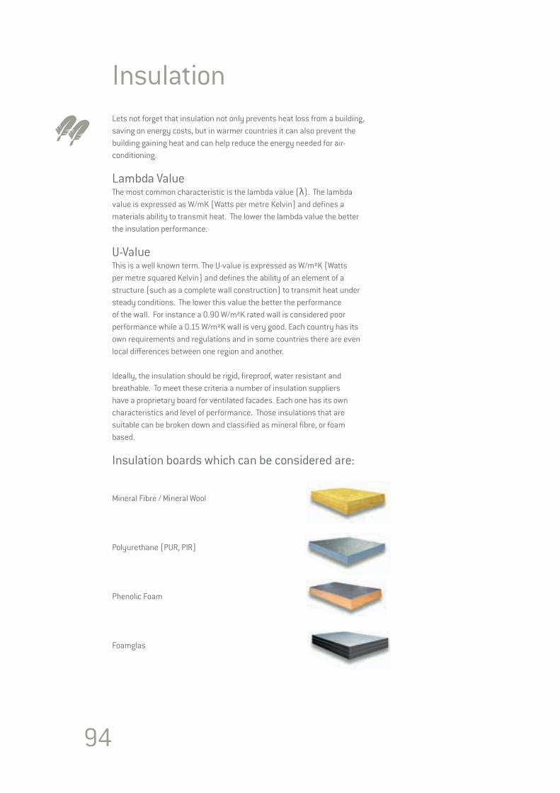
94
InsulationLets not forget that insulation not only prevents heat loss from a building, saving on energy costs, but in warmer countries it can also prevent the building gaining heat and can help reduce the energy needed for air-conditioning.
Lambda ValueThe most common characteristic is the lambda value (λ). The lambda value is expressed as W/mK (Watts per metre Kelvin) and defines a materials ability to transmit heat. The lower the lambda value the better the insulation performance.
U-Value This is a well known term. The U-value is expressed as W/m²K (Watts per metre squared Kelvin) and defines the ability of an element of a structure (such as a complete wall construction) to transmit heat under steady conditions. The lower this value the better the performance of the wall. For instance a 0.90 W/m²K rated wall is considered poor performance while a 0.15 W/m²K wall is very good. Each country has its own requirements and regulations and in some countries there are even local differences between one region and another.
Ideally, the insulation should be rigid, fireproof, water resistant and breathable. To meet these criteria a number of insulation suppliers have a proprietary board for ventilated facades. Each one has its own characteristics and level of performance. Those insulations that are suitable can be broken down and classified as mineral fibre, or foam based.
Insulation boards which can be considered are:
Mineral Fibre / Mineral Wool
Polyurethane (PUR, PIR)
Phenolic Foam
Foamglas
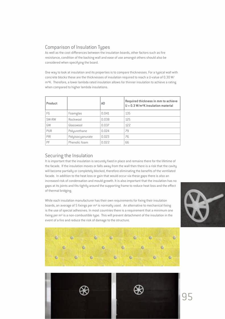
95
Comparison of Insulation TypesAs well as the cost differences between the insulation boards, other factors such as fire resistance, condition of the backing wall and ease of use amongst others should also be considered when specifying the board.
One way to look at insulation and its properties is to compare thicknesses. For a typical wall with concrete blocks these are the thicknesses of insulation required to reach a U-value of 0.30 W/m²K. Therefore, a lower lambda rated insulation allows for thinner insulation to achieve a rating when compared to higher lambda insulations.
Product ADRequired thickness in mm to achieve U = 0.3 W/m²K insulation material
FG Foamglas 0.041 135
SW-RW Rockwool 0.038 125
GW Glasswool 0.037 122
PUR Polyurethane 0.024 79
PIR Polyisocyanurate 0.023 76
PF Phenolic foam 0.022 66
Securing the InsulationIt is important that the insulation is securely fixed in place and remains there for the lifetime of the facade. If the insulation moves or falls away from the wall then there is a risk that the cavity will become partially or completely blocked, therefore eliminating the benefits of the ventilated facade. In addition to the heat loss or gain that would occur via these gaps there is also an increased risk of condensation and mould growth. It is also important that the insulation has no gaps at its joints and fits tightly around the supporting frame to reduce heat loss and the effect of thermal bridging.
While each insulation manufacturer has their own requirements for fixing their insulation boards, an average of 5 fixings per m² is normally used. An alternative to mechanical fixing is the use of special adhesives. In most countries there is a requirement that a minimum one fixing per m² is a non-combustible type. This will prevent detachment of the insulation in the event of a fire and reduce the risk of damage to the structure.
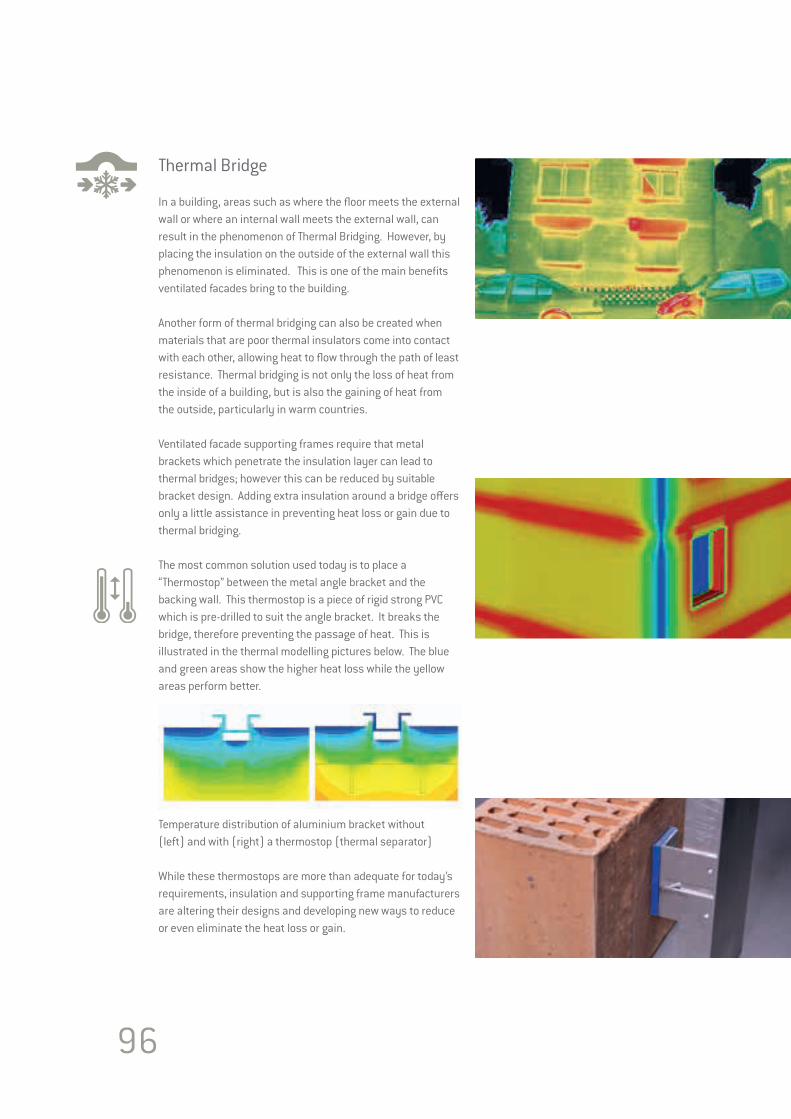
96
Thermal Bridge
In a building, areas such as where the floor meets the external wall or where an internal wall meets the external wall, can result in the phenomenon of Thermal Bridging. However, by placing the insulation on the outside of the external wall this phenomenon is eliminated. This is one of the main benefits ventilated facades bring to the building.
Another form of thermal bridging can also be created when materials that are poor thermal insulators come into contact with each other, allowing heat to flow through the path of least resistance. Thermal bridging is not only the loss of heat from the inside of a building, but is also the gaining of heat from the outside, particularly in warm countries.
Ventilated facade supporting frames require that metal brackets which penetrate the insulation layer can lead to thermal bridges; however this can be reduced by suitable bracket design. Adding extra insulation around a bridge offers only a little assistance in preventing heat loss or gain due to thermal bridging.
The most common solution used today is to place a “Thermostop” between the metal angle bracket and the backing wall. This thermostop is a piece of rigid strong PVC which is pre-drilled to suit the angle bracket. It breaks the bridge, therefore preventing the passage of heat. This is illustrated in the thermal modelling pictures below. The blue and green areas show the higher heat loss while the yellow areas perform better.
Temperature distribution of aluminium bracket without (left) and with (right) a thermostop (thermal separator) While these thermostops are more than adequate for today’s requirements, insulation and supporting frame manufacturers are altering their designs and developing new ways to reduce or even eliminate the heat loss or gain.
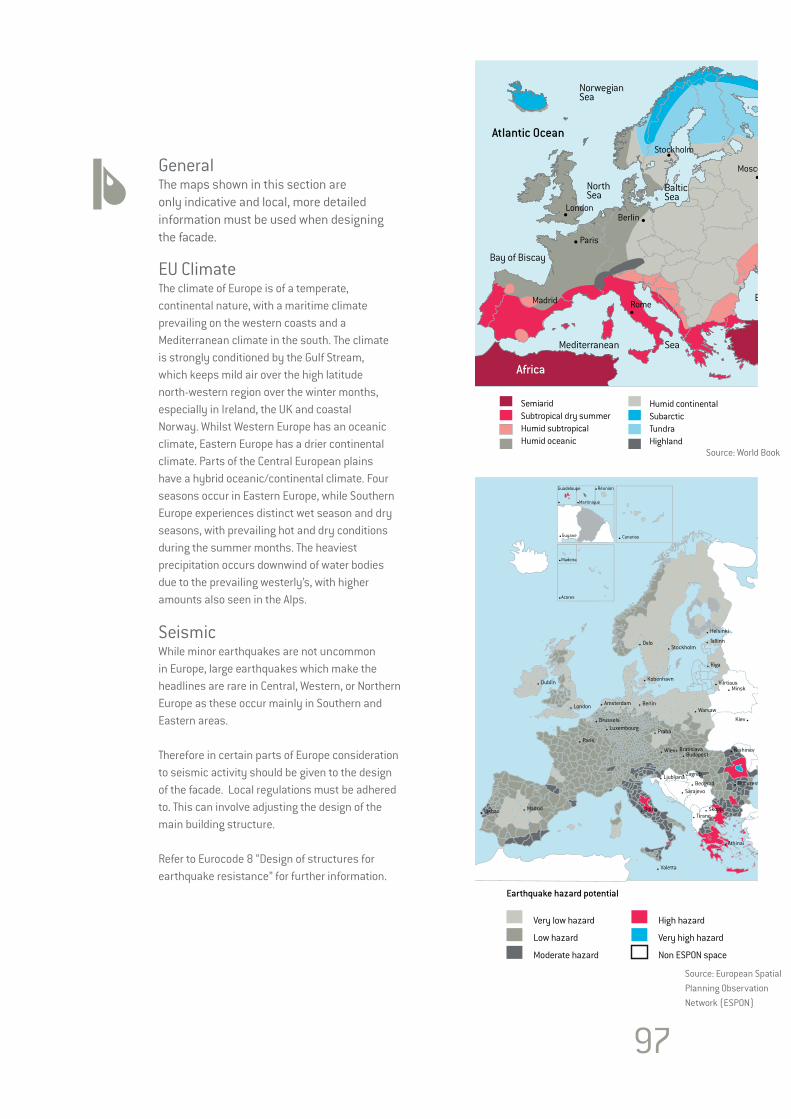
GeneralThe maps shown in this section are only indicative and local, more detailed information must be used when designing the facade.
EU ClimateThe climate of Europe is of a temperate, continental nature, with a maritime climate prevailing on the western coasts and a Mediterranean climate in the south. The climate is strongly conditioned by the Gulf Stream, which keeps mild air over the high latitude north-western region over the winter months, especially in Ireland, the UK and coastal Norway. Whilst Western Europe has an oceanic climate, Eastern Europe has a drier continental climate. Parts of the Central European plains have a hybrid oceanic/continental climate. Four seasons occur in Eastern Europe, while Southern Europe experiences distinct wet season and dry seasons, with prevailing hot and dry conditions during the summer months. The heaviest precipitation occurs downwind of water bodies due to the prevailing westerly’s, with higher amounts also seen in the Alps.
SeismicWhile minor earthquakes are not uncommon in Europe, large earthquakes which make the headlines are rare in Central, Western, or Northern Europe as these occur mainly in Southern and Eastern areas.
Therefore in certain parts of Europe consideration to seismic activity should be given to the design of the facade. Local regulations must be adhered to. This can involve adjusting the design of the main building structure.
Refer to Eurocode 8 “Design of structures for earthquake resistance” for further information.
Atlantic Ocean
Black Sea
Mediterranean Sea
Bay of Biscay
Baltic Sea
NorthSea
NorwegianSea
Asia
Africa
Paris
LondonBerlin
Moscow
Rome
SemiaridSubtropical dry summerHumid subtropicalHumid oceanic
Humid continentalSubarcticTundraHighland
Stockholm
Madrid
Very low hazard
Low hazard
Moderate hazard
Earthquake hazard potential
High hazard
Very high hazard
Non ESPON space
Minsk
Berlin
Kiev
Sarajevo
Skopje
Beograd
WienBudapest
Bratislava
Tallinn
Athinai
Roma
Ljubljana
Praha
Brussels
London
Dublin
MadridLisbao
Amsterdam
Paris
Luxembourg
Canarias
Guadeloupe
Martinique
Réunion
Guyane
Madeira
Acores
Ankara
OsloStockholm
Helsinki
Riga
Warsaw
Kobenhavn
Zagreb
Tirane
NicosraValetta
Bucuresti
Kishinev
Vilrtiaus
Moskva
Source: World Book
Source: European Spatial Planning Observation Network (ESPON)
97
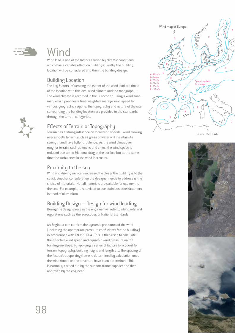
WindWind load is one of the factors caused by climatic conditions, which has a variable effect on buildings. Firstly, the building location will be considered and then the building design.
Building LocationThe key factors influencing the extent of the wind load are those of the location with the local wind climate and the topography. The wind climate is recorded in the Eurocode 1 using a wind zone map, which provides a time-weighted average wind speed for various geographic regions. The topography and nature of the site surrounding the building location are provided in the standards through the terrain categories.
Effects of Terrain or TopographyTerrain has a strong influence on local wind speeds. Wind blowing over smooth terrain, such as grass or water will maintain its strength and have little turbulence. As the wind blows over rougher terrain, such as towns and cities, the wind speed is reduced due to the frictional drag at the surface but at the same time the turbulence in the wind increases.
Proximity to the seaWind and driving rain can increase, the closer the building is to the coast. Another consideration the designer needs to address is the choice of materials. Not all materials are suitable for use next to the sea. For example, it is advised to use stainless steel fasteners instead of aluminium.
Building Design – Design for wind loadingDuring the design process the engineer will refer to standards and regulations such as the Eurocodes or National Standards.
An Engineer can confirm the dynamic pressures of the wind (including the appropriate pressure coefficients for the building) in accordance with EN 1991-1-4. This is then used to calculate the effective wind speed and dynamic wind pressure on the building envelope, by applying a series of factors to account for terrain, topography, building height and length etc. The spacing of the facade’s supporting frame is determined by calculation once the wind forces on the structure have been determined. This is normally carried out by the support frame supplier and then approved by the engineer.
A= 20 m/sB= 24m/sC=28m/sD=32m/sE=36m/sF > 36m/s
Wind map of Europe
Special regulation for the Alps
A
A
B
B
B
B
C
C
C
D
D
D
D
D
D
E
ED
E
F
G
C
Source: ESDEP WG
98
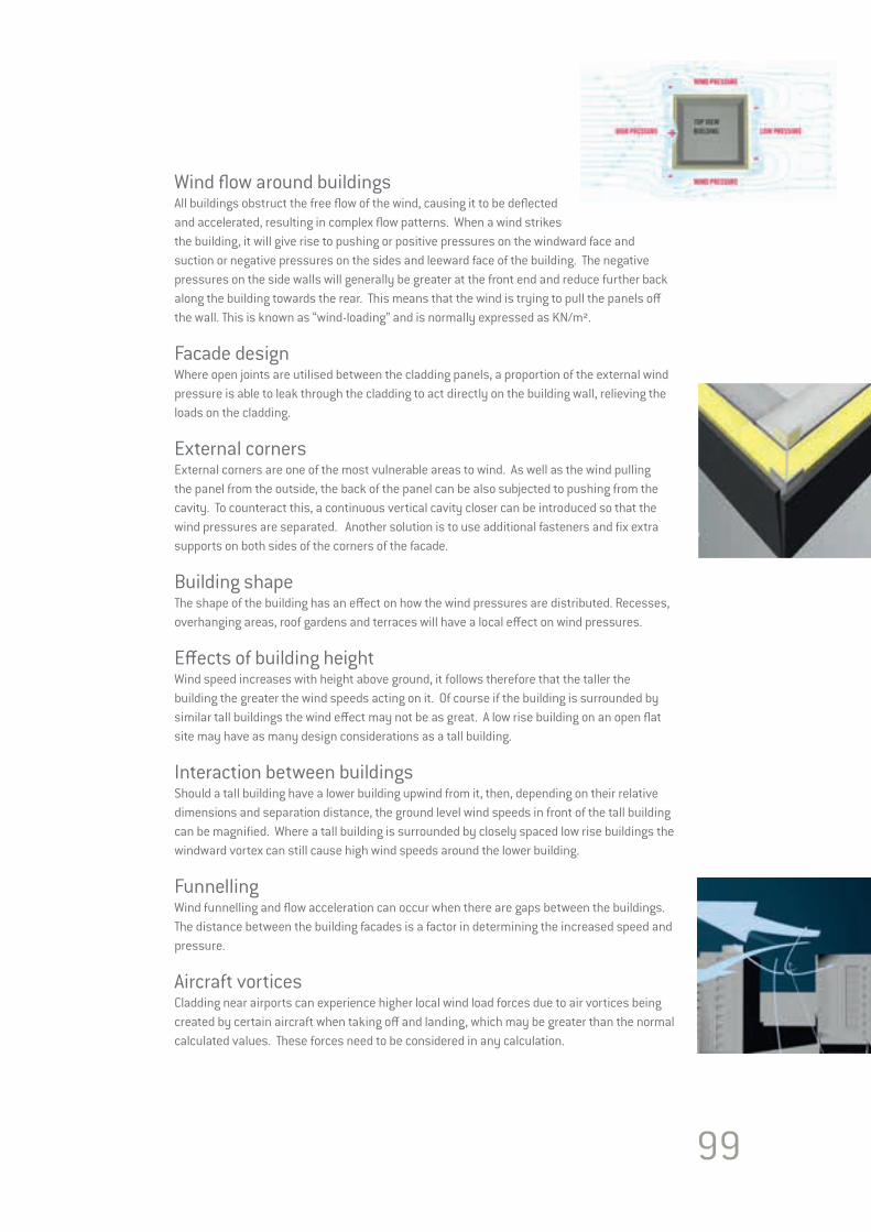
99
Wind flow around buildingsAll buildings obstruct the free flow of the wind, causing it to be deflected and accelerated, resulting in complex flow patterns. When a wind strikes the building, it will give rise to pushing or positive pressures on the windward face and suction or negative pressures on the sides and leeward face of the building. The negative pressures on the side walls will generally be greater at the front end and reduce further back along the building towards the rear. This means that the wind is trying to pull the panels off the wall. This is known as “wind-loading” and is normally expressed as KN/m².
Facade designWhere open joints are utilised between the cladding panels, a proportion of the external wind pressure is able to leak through the cladding to act directly on the building wall, relieving the loads on the cladding.
External cornersExternal corners are one of the most vulnerable areas to wind. As well as the wind pulling the panel from the outside, the back of the panel can be also subjected to pushing from the cavity. To counteract this, a continuous vertical cavity closer can be introduced so that the wind pressures are separated. Another solution is to use additional fasteners and fix extra supports on both sides of the corners of the facade.
Building shapeThe shape of the building has an effect on how the wind pressures are distributed. Recesses, overhanging areas, roof gardens and terraces will have a local effect on wind pressures.
Effects of building heightWind speed increases with height above ground, it follows therefore that the taller the building the greater the wind speeds acting on it. Of course if the building is surrounded by similar tall buildings the wind effect may not be as great. A low rise building on an open flat site may have as many design considerations as a tall building.
Interaction between buildingsShould a tall building have a lower building upwind from it, then, depending on their relative dimensions and separation distance, the ground level wind speeds in front of the tall building can be magnified. Where a tall building is surrounded by closely spaced low rise buildings the windward vortex can still cause high wind speeds around the lower building.
FunnellingWind funnelling and flow acceleration can occur when there are gaps between the buildings. The distance between the building facades is a factor in determining the increased speed and pressure. Aircraft vorticesCladding near airports can experience higher local wind load forces due to air vortices being created by certain aircraft when taking off and landing, which may be greater than the normal calculated values. These forces need to be considered in any calculation.
100

SPECIAL APPLICATION & MAINTENANCE
Section 7SPECIAL APPLICATION & MAINTENANCE

102
Special ApplicationsGeneralWhile EQUITONE panels are used as a facade cladding, they can also be used in other applications. Here we touch on some of these applications and more detailed information is available.
BalconyFor balcony panels, EQUITONE [textura] is available in 10mm thickness. The panel is coated on both sides. It is possible to have each side in a different colour. In addition to use as balcony panels, EQUITONE [textura] can also be used as divider screens between the apartment’s balconies.
The maximum panel size is 3100 x 1250mm.
Each country will have its own regulations and requirements for balcony panels which include fire and structural stability. The height of the barrier, the force this barrier needs to resist and the maximum opening size around the panel must always be considered.
The EQUITONE [textura] Balcony Panel can be incorporated into prefabricated railing systems or can be fixed to metal frames with rivets or fastened with clamps.
How the railings are anchored should be confirmed by the designer. All balcony railings should be anchored with the appropriate stainless steel anchors. The anchors can be positioned on the top, front face or underside of the balcony slab. It is recommended that 10mm wide open joints are used between adjoining balcony panels and where the panel meets a wall. This will accommodate any panel or frame movement.
Curved WallEQUITONE panels are flat. However it is possible to ease them around a curved facade. Note that the orientation of the panel is also critical. A horizontal panel bends easier than one placed vertically.
The minimum radius that an 8mm EQUITONE panel can be UNI-rivet or UNI-screw fixed to a curving facade is 12.0m. It is only possible to use the invisible fixing solutions on slow gentle curves with large radius.
When the panels are applied on a curved facade the joint will not be square but is angled to accommodate the curve. Visually it is better to keep the outer edge of the joint gap at 10mm and allow the inner edge to be less than 10mm. If not, depending on the curve, the joint could be in excess of 12mm wide. To allow this to happen it is important that the setting out of the support frame reflects this. The opposite applies to an inner curving facade.
10mm
<10mm
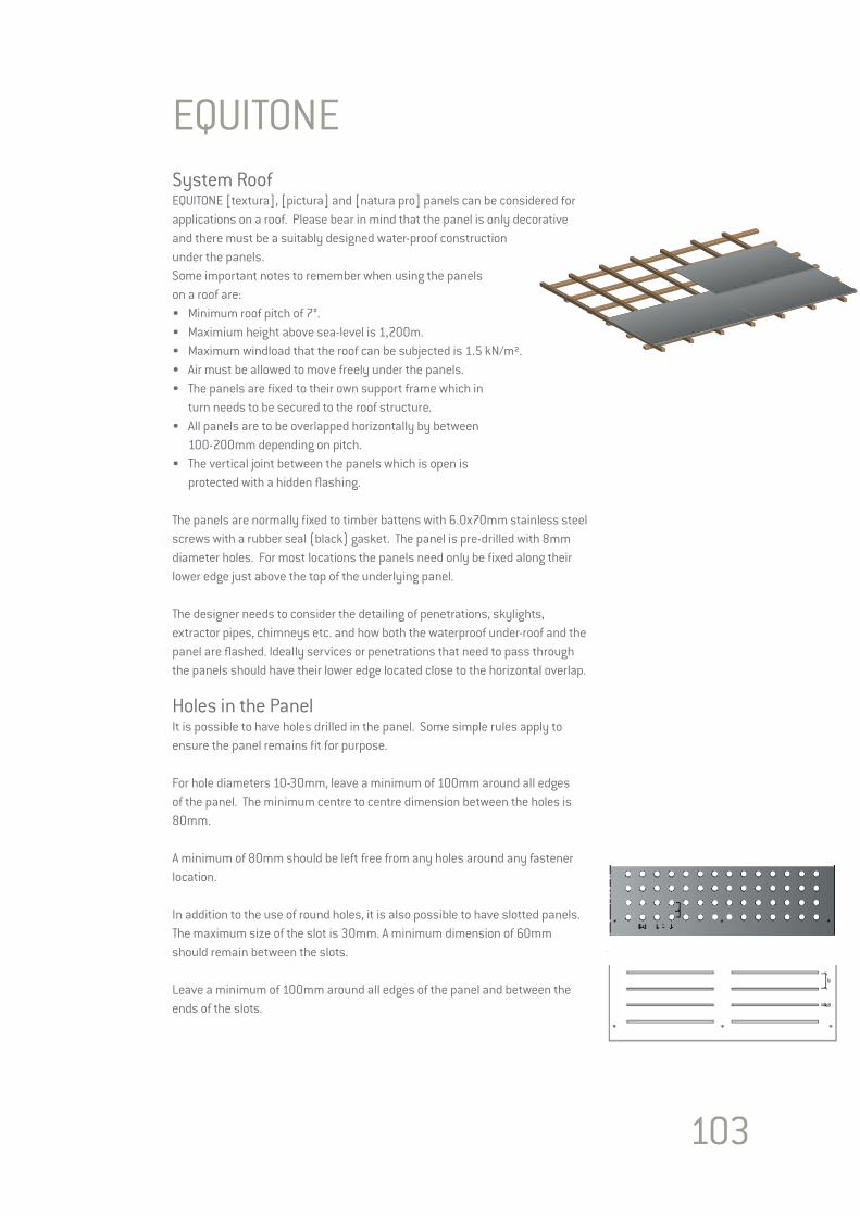
103
EQUITONE System RoofEQUITONE [textura], [pictura] and [natura pro] panels can be considered for applications on a roof. Please bear in mind that the panel is only decorative and there must be a suitably designed water-proof construction under the panels.Some important notes to remember when using the panels on a roof are:• Minimum roof pitch of 7°.• Maximium height above sea-level is 1,200m.• Maximum windload that the roof can be subjected is 1.5 kN/m².• Air must be allowed to move freely under the panels.• The panels are fixed to their own support frame which in turn needs to be secured to the roof structure.• All panels are to be overlapped horizontally by between 100-200mm depending on pitch.• The vertical joint between the panels which is open is protected with a hidden flashing.
The panels are normally fixed to timber battens with 6.0x70mm stainless steel screws with a rubber seal (black) gasket. The panel is pre-drilled with 8mm diameter holes. For most locations the panels need only be fixed along their lower edge just above the top of the underlying panel.
The designer needs to consider the detailing of penetrations, skylights, extractor pipes, chimneys etc. and how both the waterproof under-roof and the panel are flashed. Ideally services or penetrations that need to pass through the panels should have their lower edge located close to the horizontal overlap. Holes in the PanelIt is possible to have holes drilled in the panel. Some simple rules apply to ensure the panel remains fit for purpose.
For hole diameters 10-30mm, leave a minimum of 100mm around all edges of the panel. The minimum centre to centre dimension between the holes is 80mm.
A minimum of 80mm should be left free from any holes around any fastener location.
In addition to the use of round holes, it is also possible to have slotted panels.The maximum size of the slot is 30mm. A minimum dimension of 60mm should remain between the slots.
Leave a minimum of 100mm around all edges of the panel and between the ends of the slots.
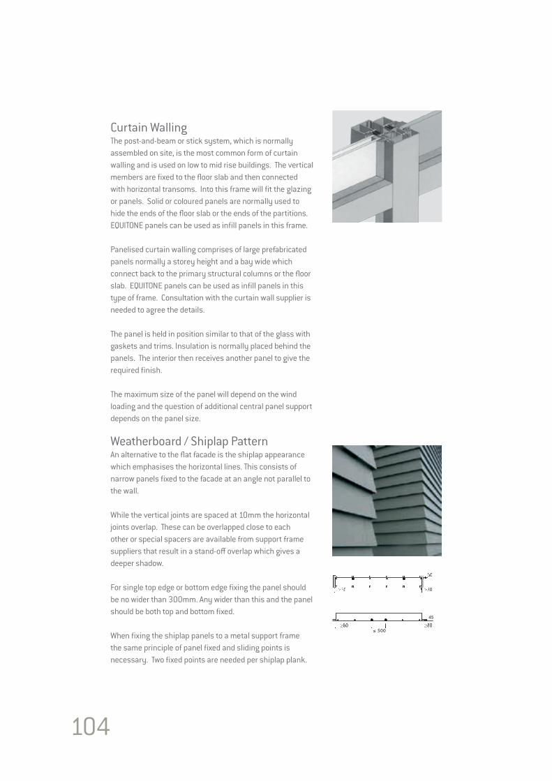
104
Curtain WallingThe post-and-beam or stick system, which is normally assembled on site, is the most common form of curtain walling and is used on low to mid rise buildings. The vertical members are fixed to the floor slab and then connected with horizontal transoms. Into this frame will fit the glazing or panels. Solid or coloured panels are normally used to hide the ends of the floor slab or the ends of the partitions. EQUITONE panels can be used as infill panels in this frame.
Panelised curtain walling comprises of large prefabricated panels normally a storey height and a bay wide which connect back to the primary structural columns or the floor slab. EQUITONE panels can be used as infill panels in this type of frame. Consultation with the curtain wall supplier is needed to agree the details.
The panel is held in position similar to that of the glass with gaskets and trims. Insulation is normally placed behind the panels. The interior then receives another panel to give the required finish.
The maximum size of the panel will depend on the wind loading and the question of additional central panel support depends on the panel size.
Weatherboard / Shiplap PatternAn alternative to the flat facade is the shiplap appearance which emphasises the horizontal lines. This consists of narrow panels fixed to the facade at an angle not parallel to the wall.
While the vertical joints are spaced at 10mm the horizontal joints overlap. These can be overlapped close to each other or special spacers are available from support frame suppliers that result in a stand-off overlap which gives a deeper shadow.
For single top edge or bottom edge fixing the panel should be no wider than 300mm. Any wider than this and the panel should be both top and bottom fixed.
When fixing the shiplap panels to a metal support frame the same principle of panel fixed and sliding points is necessary. Two fixed points are needed per shiplap plank.
45
≤ 500
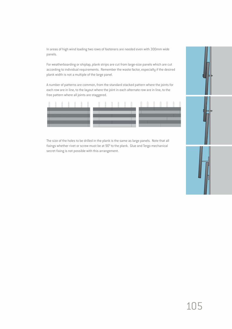
105
In areas of high wind loading two rows of fasteners are needed even with 300mm wide panels.
For weatherboarding or shiplap, plank strips are cut from large-size panels which are cut according to individual requirements. Remember the waste factor, especially if the desired plank width is not a multiple of the large panel.
A number of patterns are common, from the standard stacked pattern where the joints for each row are in line, to the layout where the joint in each alternate row are in line, to the free pattern where all joints are staggered.
The size of the holes to be drilled in the plank is the same as large panels. Note that all fixings whether rivet or screw must be at 90° to the plank. Glue and Tergo mechanical secret fixing is not possible with this arrangement.
106
MaintenanceA number of basic principles are given here. Cleaning must always take place in accordance with the recommendations of the supplier of the cleaning system and under their supervision and guarantee.
InspectionsAll facades, irrespective of the material used, should be inspected and if necessary serviced regularly. Then, unnecessary and high costs are avoided in the long term. The building also retains its continuous and attractive appearance. If one allows the soiling to work into the materials for too long, it is possible that it will have penetrated so deeply that simple cleaning is no longer possible and a more rigorous cleaning method may be needed.
The Soiling Process and Metal Cover FlashingsDust, soot, oils, greasy substances, rainwater etc. are present in the air and can be deposited on a facade. If care is taken through considerate design and application, local soiling and runs can be avoided. This can be achieved by having adequate drip-moulding, good sealing and attention to combat corrodible materials such as zinc, copper, aluminium, steel, etc. The degree and speed at which materials become soiled largely depends on the surface, chemical stability, hardness, porosity, ability to become electrostatically charged or not.
GraffitiThe UV-cured EQUITONE [pictura] surface coating provides superior protection against common colours and spray paints. It is smooth and cleanable. The EQUITONE [pictura] surface coating meets the requirements of the placement test and test cycle 2 of the Quality Association for Anti-Graffiti eV for surface-protective anti-graffiti systems (ILF 4-013/2006 report of the Institute for paints and inks eV). Graffiti can be removed with dedicated graffiti removers. Cleaners with volatile solvents should not be used. Below is a selection of appropriate graffiti removers. The application instructions of the manufacturer’s should be strictly adhered to. Costec Technologies and Cleaner Liquid Cleaner Technologies, www.costec.euScribex P3 400, www.henkel.de Rapidly 031, E-mail: [email protected]
Note that when an on-site graffiti protection is applied to the panels the appearance of the panel may change as the protection effects the light reflectance of the panel’s colour.
Maintenance Cleaning There are two methods of cleaning facades, mechanical cleaning and chemical cleaning. In principle, perform the cleaning of the facade over the entire surface, because partial cleaning can result in colour tonal differences. Normal stains can be removed with a sponge and water. The use of abrasive materials such as scourer, steel wool, etc. is not allowed, as they leave irreparable scratches on the surface.
Pressure WashingFor EQUITONE [natura], [pictura] and [textura], a pressure washer can be used in certain circumstances to remove more stubborn stains. This must be done by experienced operatives. A pressure rating of 20-30 bar is generally advised. The nozzle must remain at all times at least 60cm away from the facade. Incorrect use can lead to the removal of the panels coating.
For EQUITONE [tectiva] and [linea] a pressure cleaner with clean water at a maximum pressure of 125 bar and a maximum flow rate of 10 litres/minute can also be used. One must spray perpendicular to the surface at a distance of at least 25cm. If spraying occurs at excessive pressure or a too short distance this can cause damage to the panel surface.

107
ReferencesRelevant Documents
EN 485-2 Aluminium and aluminium alloys. Sheet, strip and plate. Mechanical properties.
EN 12467 Fibre cement flat sheets – Product Specification and test methods.EN 13501-1 Fire classification of construction products and building elements. Classification using test data from reaction to fire tests.EN 13501-2 Fire classification of construction products and building elements, Part 2 Classification using data from fire resistance tests (excluding products for use in ventilated systems).
EN 13162 Thermal insulation products for buildings. Factory made mineral wool (MW) products. Specification.EN 20140 Determination, verification and application of precision data.EN 62305 Protection against lightning. General principles.
ISO 140 Determination, verification and application of precision data.ISO 9001 Quality management systems.ISO 14001 Environmental management systems.OHSAS 18001 Occupational health and safety management systems. ISO 14025 BS EN ISO 14025:2010. Environmental labels and declarations. Type III environmental declarations. EN 15084 BS EN 15804:2012. Sustainability of construction works. Environmental product declarations. Core rules for the product category of construction products.
ETAG 0034 Guideline for European Technical Approval of kits for external wall claddings. Part 1: Ventilated cladding kits comprising cladding components and associated fixings.
EN 1991-1-4 Eurocode 1: Actions on structures – Part 1-4: General actions – Wind action.EN 1998-1 Eurocode 8: Design of structures for earthquake resistance – Part 1: General rules seismic actions and rules for buildings.
The Green Guide to Housing Specification BRE, Jayne Anderson and Nigel Howard
Rainscreen Cladding: A guide to Design Principles and practiceAnderson J.M & Gill JR
CWCT Standard for systemised building envelopes
Directive 2010/31/EU of the European Parliament and of the Council of 19 May 2010 on the energy performance of buildings
REGULATION (EC) No 1907/2006 OF THE EUROPEAN PARLIAMENT AND OF THE COUNCILof 18 December 2006 concerning the Registration, Evaluation, Authorisation and Restriction of Chemicals (REACH), establishing a European Chemicals Agency, amending Directive 1999/45/EC and repealing Council Regulation (EEC) No 793/93 and Commission Regulation (EC) No 1488/94 as well as Council Directive 76/769/EEC and Commission Directives 91/155/EEC, 93/67/EEC, 93/105/EC and 2000/21/EC

108
DisclaimerThe information in this Planning and Application Guide is based on the latest data available at the time of publishing. However, due to our committed programme of continuous product and system development we reserve the right to amend or alter the information contained herein without prior notice. For specific applications users should refer to the Technical Advisory Services on Tel: 01283 722588 and relevant Standards and Codes of Practice for guidance. The photography shown in this document should not necessarily be taken as recommendations of good practice or exact representation of colours. For true colour reference, please request product samples.

For further information, please contactTel: 01283 722588 Fax: 01283 722219 E-mail: [email protected]
Marley Eternit Limited, Lichfield Road, Branston, Burton-upon-Trent, DE14 3HD